EP4503527A1 - Wireless communication method, transmission device, reception device, and wireless communication system - Google Patents
Wireless communication method, transmission device, reception device, and wireless communication system Download PDFInfo
- Publication number
- EP4503527A1 EP4503527A1 EP22935185.3A EP22935185A EP4503527A1 EP 4503527 A1 EP4503527 A1 EP 4503527A1 EP 22935185 A EP22935185 A EP 22935185A EP 4503527 A1 EP4503527 A1 EP 4503527A1
- Authority
- EP
- European Patent Office
- Prior art keywords
- unit
- training
- single carrier
- imbalance
- signal
- Prior art date
- Legal status (The legal status is an assumption and is not a legal conclusion. Google has not performed a legal analysis and makes no representation as to the accuracy of the status listed.)
- Pending
Links
Images

Classifications
-
- H—ELECTRICITY
- H04—ELECTRIC COMMUNICATION TECHNIQUE
- H04L—TRANSMISSION OF DIGITAL INFORMATION, e.g. TELEGRAPHIC COMMUNICATION
- H04L27/00—Modulated-carrier systems
- H04L27/32—Carrier systems characterised by combinations of two or more of the types covered by groups H04L27/02, H04L27/10, H04L27/18 or H04L27/26
- H04L27/34—Amplitude- and phase-modulated carrier systems, e.g. quadrature-amplitude modulated carrier systems
- H04L27/38—Demodulator circuits; Receiver circuits
- H04L27/3845—Demodulator circuits; Receiver circuits using non - coherent demodulation, i.e. not using a phase synchronous carrier
- H04L27/3854—Demodulator circuits; Receiver circuits using non - coherent demodulation, i.e. not using a phase synchronous carrier using a non - coherent carrier, including systems with baseband correction for phase or frequency offset
- H04L27/3863—Compensation for quadrature error in the received signal
-
- H—ELECTRICITY
- H04—ELECTRIC COMMUNICATION TECHNIQUE
- H04L—TRANSMISSION OF DIGITAL INFORMATION, e.g. TELEGRAPHIC COMMUNICATION
- H04L27/00—Modulated-carrier systems
- H04L27/26—Systems using multi-frequency codes
- H04L27/2601—Multicarrier modulation systems
-
- H—ELECTRICITY
- H04—ELECTRIC COMMUNICATION TECHNIQUE
- H04B—TRANSMISSION
- H04B1/00—Details of transmission systems, not covered by a single one of groups H04B3/00 - H04B13/00; Details of transmission systems not characterised by the medium used for transmission
- H04B1/02—Transmitters
-
- H—ELECTRICITY
- H04—ELECTRIC COMMUNICATION TECHNIQUE
- H04L—TRANSMISSION OF DIGITAL INFORMATION, e.g. TELEGRAPHIC COMMUNICATION
- H04L25/00—Baseband systems
- H04L25/02—Details ; arrangements for supplying electrical power along data transmission lines
- H04L25/03—Shaping networks in transmitter or receiver, e.g. adaptive shaping networks
- H04L25/03828—Arrangements for spectral shaping; Arrangements for providing signals with specified spectral properties
- H04L25/03834—Arrangements for spectral shaping; Arrangements for providing signals with specified spectral properties using pulse shaping
-
- H—ELECTRICITY
- H04—ELECTRIC COMMUNICATION TECHNIQUE
- H04L—TRANSMISSION OF DIGITAL INFORMATION, e.g. TELEGRAPHIC COMMUNICATION
- H04L27/00—Modulated-carrier systems
- H04L27/26—Systems using multi-frequency codes
- H04L27/2601—Multicarrier modulation systems
- H04L27/2602—Signal structure
- H04L27/261—Details of reference signals
- H04L27/2613—Structure of the reference signals
-
- H—ELECTRICITY
- H04—ELECTRIC COMMUNICATION TECHNIQUE
- H04L—TRANSMISSION OF DIGITAL INFORMATION, e.g. TELEGRAPHIC COMMUNICATION
- H04L27/00—Modulated-carrier systems
- H04L27/26—Systems using multi-frequency codes
- H04L27/2601—Multicarrier modulation systems
- H04L27/2626—Arrangements specific to the transmitter only
- H04L27/2627—Modulators
- H04L27/264—Pulse-shaped multi-carrier, i.e. not using rectangular window
- H04L27/26412—Filtering over the entire frequency band, e.g. filtered orthogonal frequency-division multiplexing [OFDM]
-
- H—ELECTRICITY
- H04—ELECTRIC COMMUNICATION TECHNIQUE
- H04L—TRANSMISSION OF DIGITAL INFORMATION, e.g. TELEGRAPHIC COMMUNICATION
- H04L27/00—Modulated-carrier systems
- H04L27/32—Carrier systems characterised by combinations of two or more of the types covered by groups H04L27/02, H04L27/10, H04L27/18 or H04L27/26
- H04L27/34—Amplitude- and phase-modulated carrier systems, e.g. quadrature-amplitude modulated carrier systems
- H04L27/36—Modulator circuits; Transmitter circuits
- H04L27/366—Arrangements for compensating undesirable properties of the transmission path between the modulator and the demodulator
-
- H—ELECTRICITY
- H04—ELECTRIC COMMUNICATION TECHNIQUE
- H04W—WIRELESS COMMUNICATION NETWORKS
- H04W72/00—Local resource management
- H04W72/04—Wireless resource allocation
- H04W72/044—Wireless resource allocation based on the type of the allocated resource
Definitions
- the present invention relates to a radio communication method, a transmitter, a receiver, and a radio communication system.
- orthogonal components I and Q to be received may become signals of different attenuation and phase rotation under the influence of different interference (IQ imbalance).
- a channel response value and an IQ imbalance value can be simultaneously estimated, using two or more pilot signals, and the IQ imbalance can be compensated for (see, for example, NPL 1) .
- OFDM orthogonal frequency division multiplexing
- the IQ imbalance can be estimated using the symmetric subcarriers of two or more training OFDM symbols (see, for example, NPL 2).
- the present invention has been achieved in view of the above-mentioned problem, and an object thereof is to provide a radio communication method, a transmitter, a receiver and a radio communication system capable of estimating and compensating for IQ imbalance even when performing the single carrier transmission.
- a radio communication method is a radio communication method for transmitting a signal from a transmitter to a receiver using a single carrier, in which the transmitter generates two or more training signals using a symmetric subcarrier at the time of training to perform an OFDM modulation, and shapes a spectrum of each of the OFDM-modulated training signals to be close to a single carrier spectrum, and in which the receiver adjusts the timing of two or more training signals, using a single carrier time domain correlation sequence at the time of training, estimates a channel response and an IQ imbalance from the two or more training signals whose timing is adjusted, compensates for the estimated IQ imbalance, and demodulates the compensated signal.
- a transmitter is a transmitter which transmits a signal to a receiver using a single carrier, the transmitter includes an OFDM modulation unit which generates two or more training signals using a symmetric subcarrier at the time of training and performs an OFDM modulation; and a shaping unit which shapes a spectrum of each of the training signals OFDM-modulated by the OFDM modulation unit to be close to a single carrier spectrum.
- a receiver is a receiver which receives a signal from a transmitter using a single carrier, the receiver includes a timing adjusting unit which adjusts timing of two or more training signals using a single carrier time domain correlation sequence at the time of training; an estimating unit which estimates a channel response and an IQ imbalance from the two or more training signals whose timing is adjusted by the timing adjusting unit; a compensating unit which compensates for the IQ imbalance estimated by the estimating unit; and a demodulating unit which demodulates a signal compensated by the compensating unit.
- a radio communication system is a radio communication system which transmits a signal from a transmitter to a receiver using a single carrier
- the transmitter includes an OFDM modulating unit which generates two or more training signals using a symmetric subcarrier at the time of training to perform an OFDM modulation, and a shaping unit which shapes a spectrum of each of the training signals OFDM-modulated by the OFDM modulating unit to be close to a single carrier spectrum
- the receiver includes a timing adjusting unit which adjusts timing of two or more training signals, using a single carrier time domain correlation sequence at the time of training, an estimating unit which estimates a channel response and an IQ imbalance from two or more training signals whose timing is adjusted by the timing adjusting unit, a compensating unit which compensates for the IQ imbalance estimated by the estimating unit, and a demodulating unit which demodulates the signal compensated by the compensating unit.
- Fig. 1 is a diagram showing the function of a receiver which that enables estimation of IQ imbalance using a training signal.
- a signal having a frequency generated by an oscillation circuit 1 is mixed with a received signal Rx by two mixers 2 and received.
- the received signal Rx distorted by the imbalance of IQ is represented by the following equation (1).
- y n 1 + ge ⁇ j ⁇ h + 1 ⁇ ge j ⁇ h ⁇ 2
- a phase compensation unit 3 for compensating for the phase imbalance of the symmetric subcarriers is provided in the preceding stage of one mixer 2.
- the amplifier 4 which amplifies the signal whose phase imbalance is compensated, among the two amplifiers 4, compensates for the gain imbalance.
- the IQ imbalance caused by an imbalance between the quadrature modulation and the demodulator can be estimated from two or more training (pilot) signals simultaneously with the channel response (channel response) h, and can be compensated (see NPL 1).
- [Math. 12] 2 Y k ′ 1 + ge ⁇ j ⁇ H k + 1 ⁇ ge j ⁇ H ⁇ k ⁇
- [Math. 13] 2 Y ⁇ k ⁇ ′ 1 ⁇ ge ⁇ j ⁇ H k + 1 + ge j ⁇ H ⁇ k ⁇
- [Math. 16] 2 Y k “ 1 + ge ⁇ j ⁇ H k ⁇ 1 ⁇ ge j ⁇ H ⁇ k ⁇
- [Math. 17] 2 Y ⁇ k ⁇ " 1 ⁇ ge ⁇ j ⁇ H k ⁇ 1 + ge j ⁇ H ⁇ k ⁇
- the IQ imbalance can be estimated by utilizing two or more training OFDM symbols for mutual leakage of symmetric subcarriers (indexes k and -k). That is, under the frequency selective fading channel, the IQ imbalance can be estimated simultaneously with the channel estimation in the frequency domain in the OFDM transmission (see NPL 2).
- the radio communication system according to an embodiment capable of estimating and compensating for the IQ imbalance, even when the single carrier transmission is performed will be described.
- the radio communication system according to an embodiment performs OFDM modulation training to estimate and compensate for the IQ imbalance in a training stage in order to perform the single carrier transmission from the transmitter to the receiver.
- the transmitter that performs the single carrier transmission generates a channel estimation training field by the OFDM modulation, and performs spectrum shaping to approach a spectrum of the single carrier.
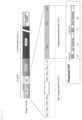
- Fig. 2 is a diagram showing a packet that is transmitted by the transmitter of the radio communication system equipped with a function compliant with IEEE 802.11ad-SC (see NPL 3) and a function of estimating and compensating for the IQ imbalance in the single carrier transmission.
- the transmitter generates a channel estimation training field in the single carrier transmission by the OFDM modulation, and performs the symmetric subcarrier (index k and -k) training. At this time, the transmitter performs the spectrum shaping (SS) to bring the spectrum of the modulation signal close to the spectrum of the single carrier.
- SS spectrum shaping
- the transmitter changes the channel estimation field (CEF) in the IEEE 802.11ad-SC by the OFDM modulation and the spectrum shaping.
- CEF channel estimation field
- the CEF includes a first training (1st training) signal and a second training (2nd training) signal each having a guard interval (GI).
- GI guard interval
- the receiver Since it is difficult to synchronize the symbol timing in the symmetric subcarrier training, the receiver according to an embodiment synchronizes two training symbols, using another single carrier time domain correlation sequence (short routing field (STF) in Fig. 2 ).
- STF short routing field
- FIG. 3 is a diagram showing functions of the transmitter according to an embodiment.
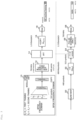
- the transmitter includes functions of an OFDM modulation unit 10, a shaping unit 12, an IFFT unit 14, a copy unit 16, and a DA unit 18 at the time of training, and generates the CEF including the first training signal and the second training signal shown in Fig. 2 .
- the OFDM modulation unit 10 performs the OFDM modulation of the first training and the second training of the frequency domain. That is, the OFDM modulation unit 10 generates two or more training signals using the symmetric subcarrier at the time of training and performs the OFDM modulation.
- the shaping unit 12 performs the spectrum shaping so that each spectrum of the training signal subjected to the OFDM modulation by the OFDM modulation unit 10 is close to the single carrier spectrum.
- the IFFT unit 14 performs an inverse Fourier fast transformation.
- the copy unit 16 copies the training signal and adds GI to each of them.
- the DA unit 18 is a DAC for performing the DA conversion of the first training signal and the second training signal.
- the transmitter When performing the single carrier transmission, the transmitter includes, for example, functions of a QAM processing unit 20, a GI processing unit 22, a sampling unit 24, a shaping unit 26, and a DA unit 28.
- the QAM processing unit 20 performs processing for making a signal for performing the single carrier transmission into a constellation according to a QAM map.
- the GI processing unit 22 performs processing for removing the GI.
- the sampling unit 24 performs double up-sampling.
- the shaping unit 26 shape a pulse of the transmission signal.
- the DA unit 28 is a DAC for DA-converting the transmission signal, and is shared by, for example, a DAC constituting the DA unit 18.
- Fig. 4 is a diagram showing functions of the receiver according to an embodiment.
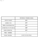
- Fig. 5 is a diagram showing signals referenced when each function of the receiver shown in Fig. 4 processes each packet.
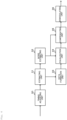
- the receiver includes a timing adjusting unit 30, an estimating unit 31, a noise estimating unit 32, a data forming unit 33, an equalization unit 34, a compensation unit 35, and a demodulating unit 36, and estimates and compensates for the IQ imbalance between the first training signal and the second training signal.
- the timing adjusting unit 30 adjusts the timing of two or more training signals, by using the single carrier time domain correlation sequence at the time of training. For example, the timing adjusting unit 30 synchronizes symbol timings of two or more training signals by using the STF for a received signal subjected to 1/2 down-sampling with a matched filter at the time of training, except the CEF at the time of data transmission, and performs the packet detection and the frequency correction (see Fig. 5 ).
- the estimating unit 31 estimates a channel frequency response (CFR) and an IQ imbalance (IQI) from two or more training signals whose timing is adjusted by the timing adjusting unit 30 in a frequency domain, and outputs an estimation result to the noise estimating unit 32 and the data forming unit 33.
- CFR channel frequency response
- IQI IQ imbalance
- the noise estimating unit 32 estimates noise in a time domain, and outputs an estimation result to the equalization unit 34 and the compensation unit 35.
- the data forming unit 33 extracts a data field in the time domain, forms the data field into a data block again, converts the data field from the time domain into a frequency domain, and outputs it to the equalization unit 34.
- the equalization unit 34 performs a frequency domain equalization (FDE) on the data field, using a result of noise estimation by the noise estimating unit 32 and the data block re-formed by the data forming unit 33 in the frequency domain, and outputs the result to the compensation unit 35.
- FDE frequency domain equalization
- the compensation unit 35 performs conversion from the frequency domain to the time domain, and compensates for the IQ imbalance estimated by the estimating unit 31. More specifically, the compensation unit 35 compensates for the phase and gain of the IQ imbalance, using the result of noise estimation by the noise estimating unit 32 and the data field subjected to equalization processing by the equalization unit 34 in the time domain.
- the demodulating unit 36 demodulates the signal received by the compensation unit 35. More specifically, the demodulating unit 36 performs a bit recovery of the DMG data by de-mapping of the DMG data and decoding of the DMG data.
- the transmitter since the transmitter generates two or more training signals using the symmetric subcarrier at the time of training, performs the OFDM modulation, and shapes each spectrum of the OFDM-modulated training signals to be close to a single carrier spectrum, the IQ imbalance can be estimated and compensated even when performing the single carrier transmission.
Landscapes
- Engineering & Computer Science (AREA)
- Computer Networks & Wireless Communication (AREA)
- Signal Processing (AREA)
- Physics & Mathematics (AREA)
- Spectroscopy & Molecular Physics (AREA)
- Power Engineering (AREA)
- Digital Transmission Methods That Use Modulated Carrier Waves (AREA)
- Transmitters (AREA)
- Mobile Radio Communication Systems (AREA)
Abstract
Description
- The present invention relates to a radio communication method, a transmitter, a receiver, and a radio communication system.
- In a single carrier transmission using orthogonal modulation and demodulation, orthogonal components I and Q to be received may become signals of different attenuation and phase rotation under the influence of different interference (IQ imbalance).
- In a subcarrier transmission such as orthogonal frequency division multiplexing (OFDM), when the IQ imbalance occurs, a channel response value and an IQ imbalance value can be simultaneously estimated, using two or more pilot signals, and the IQ imbalance can be compensated for (see, for example, NPL 1) .
- For example, in the OFDM, since symmetric subcarriers (indices k and -k) leak from each other, the IQ imbalance can be estimated using the symmetric subcarriers of two or more training OFDM symbols (see, for example, NPL 2).
-
- [NPL 1] T. Schenk, "RF Imperfections in High-rate Wireless Systems Impact and Digital Compensation", Springer, 2008, pp. 139-145
- [NPL 2] Keima Egashira, 2 others, "A Novel IQ Imbalance Compensation Method with Pilot-Signals for OFDM System", Institute of Electronics, Information and Communication Engineers journal, B Vol. J91-B No. 5, 2008, pp. 558-565.
- [NPL 3] Part11: Wireless LAN Medium Access Control (MAC) and Physical Layer (PHY) Specifications, Amendments: Enhancements for Very High Throughput in the 60 GHz Band, IEEE Computer Society, IEEE Std. 802.11adTM-2012.
- However, in the related art, in the single carrier transmission under a frequency selective fading communication path, since there is no symmetric subcarrier, training arrangement for the symmetric subcarrier cannot be performed, and quality deterioration due to IQ imbalance cannot be prevented.
- The present invention has been achieved in view of the above-mentioned problem, and an object thereof is to provide a radio communication method, a transmitter, a receiver and a radio communication system capable of estimating and compensating for IQ imbalance even when performing the single carrier transmission.
- A radio communication method according to an embodiment of the present invention is a radio communication method for transmitting a signal from a transmitter to a receiver using a single carrier, in which the transmitter generates two or more training signals using a symmetric subcarrier at the time of training to perform an OFDM modulation, and shapes a spectrum of each of the OFDM-modulated training signals to be close to a single carrier spectrum, and in which the receiver adjusts the timing of two or more training signals, using a single carrier time domain correlation sequence at the time of training, estimates a channel response and an IQ imbalance from the two or more training signals whose timing is adjusted, compensates for the estimated IQ imbalance, and demodulates the compensated signal.
- A transmitter according to an embodiment of the present invention is a transmitter which transmits a signal to a receiver using a single carrier, the transmitter includes an OFDM modulation unit which generates two or more training signals using a symmetric subcarrier at the time of training and performs an OFDM modulation; and a shaping unit which shapes a spectrum of each of the training signals OFDM-modulated by the OFDM modulation unit to be close to a single carrier spectrum.
- A receiver according to an embodiment of the present invention is a receiver which receives a signal from a transmitter using a single carrier, the receiver includes a timing adjusting unit which adjusts timing of two or more training signals using a single carrier time domain correlation sequence at the time of training; an estimating unit which estimates a channel response and an IQ imbalance from the two or more training signals whose timing is adjusted by the timing adjusting unit; a compensating unit which compensates for the IQ imbalance estimated by the estimating unit; and a demodulating unit which demodulates a signal compensated by the compensating unit.
- A radio communication system according to an embodiment of the present invention is a radio communication system which transmits a signal from a transmitter to a receiver using a single carrier, in which the transmitter includes an OFDM modulating unit which generates two or more training signals using a symmetric subcarrier at the time of training to perform an OFDM modulation, and a shaping unit which shapes a spectrum of each of the training signals OFDM-modulated by the OFDM modulating unit to be close to a single carrier spectrum, and in which the receiver includes a timing adjusting unit which adjusts timing of two or more training signals, using a single carrier time domain correlation sequence at the time of training, an estimating unit which estimates a channel response and an IQ imbalance from two or more training signals whose timing is adjusted by the timing adjusting unit, a compensating unit which compensates for the IQ imbalance estimated by the estimating unit, and a demodulating unit which demodulates the signal compensated by the compensating unit.
- According to the present invention, it is possible to estimate and compensate for the IQ imbalance even when the single carrier transmission is performed.
-
- [
Fig. 1] Fig. 1 is a diagram showing the functionality of a receiver that enables estimation of IQ imbalance using a training signal. - [
Fig. 2] Fig. 2 is a diagram showing a packet transmitted by a transmitter. - [
Fig. 3] Fig. 3 is a diagram showing functions of the transmitter according to an embodiment. - [
Fig. 4] Fig. 4 is a diagram showing functions of the receiver according to an embodiment. - [
Fig. 5] Fig. 5 is a diagram showing signals referenced when each function of the receiver shown inFig. 4 processes each packet. - First, the background leading to the present invention will be described.
Fig. 1 is a diagram showing the function of a receiver which that enables estimation of IQ imbalance using a training signal. - In the receiver shown in
Fig. 1 , a signal having a frequency generated by anoscillation circuit 1 is mixed with a received signal Rx by twomixers 2 and received. - The received signal Rx distorted by the imbalance of IQ is represented by the following equation (1).
[Math. 1]
- Further, Sn=1 (1st pilot) of the transmission signal Tx at time n is represented by the following equation (2).
[Math. 2]
- Sn=J (2nd pilot) of the transmission signal Tx at time n is represented by the following equation (3).
[Math. 3]
- Here, the following equations (4) and (5) are assumed to be A and B.
[Math. 4]

- At this time, the estimation result of the channel response, the estimation result of the gain imbalance, and the estimation result of the phase imbalance are expressed by the following equation (6), (7), and (8).
[Math. 6]


- A phase compensation unit 3 for compensating for the phase imbalance of the symmetric subcarriers is provided in the preceding stage of one
mixer 2. - The amplifier 4, which amplifies the signal whose phase imbalance is compensated, among the two amplifiers 4, compensates for the gain imbalance.
- Then, it is possible to output the signal of I-Ch obtained by AD-converting the ADC 6 via a LPF 5, and the signal of Q-Ch obtained by AD-converting the ADC 6 via the LPF 5 by compensating for the phase imbalance and the gain imbalance.
- At this time, the channel response at the compensated time n is represented by the following equation (9).
[Math. 9]
- In this way, the IQ imbalance caused by an imbalance between the quadrature modulation and the demodulator can be estimated from two or more training (pilot) signals simultaneously with the channel response (channel response) h, and can be compensated (see NPL 1).
- When the IQ imbalance is estimated in the OFDM transmission, for example, it is possible to use signals of the following equation (10) in a subcarrier k of the received signal Rx in a frequency domain and the following equation (11) in the symmetric subcarrier-k.
[Math. 10]

- Hk : CFR of subcarrier K
- Sk : Tx signal of frequency domain
- g ≧ 0: Gain imbalance (frequency independent)
- ϕ: Phase imbalance (frequency independent)
- The transmission signal Sk=S-k=1 in the frequency domain in the first training (1st training) OFDM symbol is represented by the following equations (12) and (13), respectively.
[Math. 12]

- At this time, the following equations (14) and (15) are assumed to be A and B.
[Math. 14]

- The transmission signal Sk=S-k=-1 in the frequency domain in the second training (2nd Training) OFDM symbol is represented by the following equations (16) and (17), respectively.
[Math. 16]

- At this time, the following equations (18) and (19) are assumed to be C and D, respectively.
[Math. 18]

- At this time, the estimation result of the CFR (channel frequency response) of the subcarrier k, the estimation result of the CFR of the subcarrier k, the estimation result of the gain imbalance, and the estimation result of the phase imbalance are shown by the following equations (20) to (23).
[Math. 20]


- The compensation result at this time is represented by the following equation (24).
[Math. 24]
- In this way, the IQ imbalance can be estimated by utilizing two or more training OFDM symbols for mutual leakage of symmetric subcarriers (indexes k and -k). That is, under the frequency selective fading channel, the IQ imbalance can be estimated simultaneously with the channel estimation in the frequency domain in the OFDM transmission (see NPL 2).
- Next, a radio communication system according to an embodiment capable of estimating and compensating for the IQ imbalance, even when the single carrier transmission is performed will be described. The radio communication system according to an embodiment performs OFDM modulation training to estimate and compensate for the IQ imbalance in a training stage in order to perform the single carrier transmission from the transmitter to the receiver.
- For example, the transmitter that performs the single carrier transmission generates a channel estimation training field by the OFDM modulation, and performs spectrum shaping to approach a spectrum of the single carrier.
-
Fig. 2 is a diagram showing a packet that is transmitted by the transmitter of the radio communication system equipped with a function compliant with IEEE 802.11ad-SC (see NPL 3) and a function of estimating and compensating for the IQ imbalance in the single carrier transmission. - The transmitter according to an embodiment generates a channel estimation training field in the single carrier transmission by the OFDM modulation, and performs the symmetric subcarrier (index k and -k) training. At this time, the transmitter performs the spectrum shaping (SS) to bring the spectrum of the modulation signal close to the spectrum of the single carrier.
- That is, the transmitter according to an embodiment of the present invention changes the channel estimation field (CEF) in the IEEE 802.11ad-SC by the OFDM modulation and the spectrum shaping.
- At this time, the CEF includes a first training (1st training) signal and a second training (2nd training) signal each having a guard interval (GI).
- Since it is difficult to synchronize the symbol timing in the symmetric subcarrier training, the receiver according to an embodiment synchronizes two training symbols, using another single carrier time domain correlation sequence (short routing field (STF) in
Fig. 2 ). - Next, functions included in the transmitter according to an embodiment will be described.
Fig. 3 is a diagram showing functions of the transmitter according to an embodiment. - As shown in
Fig. 3 , the transmitter according to an embodiment includes functions of anOFDM modulation unit 10, a shapingunit 12, anIFFT unit 14, acopy unit 16, and aDA unit 18 at the time of training, and generates the CEF including the first training signal and the second training signal shown inFig. 2 . - The
OFDM modulation unit 10 performs the OFDM modulation of the first training and the second training of the frequency domain. That is, theOFDM modulation unit 10 generates two or more training signals using the symmetric subcarrier at the time of training and performs the OFDM modulation. - The shaping
unit 12 performs the spectrum shaping so that each spectrum of the training signal subjected to the OFDM modulation by theOFDM modulation unit 10 is close to the single carrier spectrum. - The
IFFT unit 14 performs an inverse Fourier fast transformation. Thecopy unit 16 copies the training signal and adds GI to each of them. TheDA unit 18 is a DAC for performing the DA conversion of the first training signal and the second training signal. - When performing the single carrier transmission, the transmitter includes, for example, functions of a
QAM processing unit 20, aGI processing unit 22, asampling unit 24, a shapingunit 26, and aDA unit 28. - The
QAM processing unit 20 performs processing for making a signal for performing the single carrier transmission into a constellation according to a QAM map. TheGI processing unit 22 performs processing for removing the GI. Thesampling unit 24 performs double up-sampling. The shapingunit 26 shape a pulse of the transmission signal. TheDA unit 28 is a DAC for DA-converting the transmission signal, and is shared by, for example, a DAC constituting theDA unit 18. - Next, functions included in the receiver according to an embodiment will be explained.
Fig. 4 is a diagram showing functions of the receiver according to an embodiment.Fig. 5 is a diagram showing signals referenced when each function of the receiver shown inFig. 4 processes each packet. - As shown in
Fig. 4 , the receiver according to an embodiment includes atiming adjusting unit 30, an estimatingunit 31, anoise estimating unit 32, adata forming unit 33, anequalization unit 34, acompensation unit 35, and ademodulating unit 36, and estimates and compensates for the IQ imbalance between the first training signal and the second training signal. - The
timing adjusting unit 30 adjusts the timing of two or more training signals, by using the single carrier time domain correlation sequence at the time of training. For example, thetiming adjusting unit 30 synchronizes symbol timings of two or more training signals by using the STF for a received signal subjected to 1/2 down-sampling with a matched filter at the time of training, except the CEF at the time of data transmission, and performs the packet detection and the frequency correction (seeFig. 5 ). - The estimating
unit 31 estimates a channel frequency response (CFR) and an IQ imbalance (IQI) from two or more training signals whose timing is adjusted by thetiming adjusting unit 30 in a frequency domain, and outputs an estimation result to thenoise estimating unit 32 and thedata forming unit 33. - The
noise estimating unit 32 estimates noise in a time domain, and outputs an estimation result to theequalization unit 34 and thecompensation unit 35. - The
data forming unit 33 extracts a data field in the time domain, forms the data field into a data block again, converts the data field from the time domain into a frequency domain, and outputs it to theequalization unit 34. - The
equalization unit 34 performs a frequency domain equalization (FDE) on the data field, using a result of noise estimation by thenoise estimating unit 32 and the data block re-formed by thedata forming unit 33 in the frequency domain, and outputs the result to thecompensation unit 35. - The
compensation unit 35 performs conversion from the frequency domain to the time domain, and compensates for the IQ imbalance estimated by the estimatingunit 31. More specifically, thecompensation unit 35 compensates for the phase and gain of the IQ imbalance, using the result of noise estimation by thenoise estimating unit 32 and the data field subjected to equalization processing by theequalization unit 34 in the time domain. - The
demodulating unit 36 demodulates the signal received by thecompensation unit 35. More specifically, thedemodulating unit 36 performs a bit recovery of the DMG data by de-mapping of the DMG data and decoding of the DMG data. - In this way, in the radio communication system according to an embodiment, since the transmitter generates two or more training signals using the symmetric subcarrier at the time of training, performs the OFDM modulation, and shapes each spectrum of the OFDM-modulated training signals to be close to a single carrier spectrum, the IQ imbalance can be estimated and compensated even when performing the single carrier transmission.
-
- 10
- OFDM modulation unit
- 12
- Shaping unit
- 14
- IFFT unit
- 16
- Copy unit
- 18
- DA unit
- 20
- QAM processing unit
- 22
- GI processing unit
- 24
- Sampling unit
- 26
- Shaping unit
- 28
- DA unit
- 30
- Timing adjusting unit
- 31
- Estimating unit
- 32
- Noise estimating unit
- 33
- Data formation unit
- 34
- Equalization unit
- 35
- Compensating unit
- 36
- Demodulating unit
Claims (4)
- A radio communication method for transmitting a signal from a transmitter to a receiver using a single carrier,wherein the transmittergenerates two or more training signals using a symmetric subcarrier at the time of training to perform an OFDM modulation, andshapes a spectrum of each of the OFDM-modulated training signals to be close to a single carrier spectrum, andwherein the receiveradjusts the timing of two or more training signals, using a single carrier time domain correlation sequence at the time of training,estimates a channel response and an IQ imbalance from the two or more training signals whose timing is adjusted,compensates for the estimated IQ imbalance, and demodulates the compensated signal.
- A transmitter which transmits a signal to a receiver using a single carrier, comprising:an OFDM modulation unit which generates two or more training signals using a symmetric subcarrier at the time of training and performs an OFDM modulation; anda shaping unit which shapes a spectrum of each of the training signals OFDM-modulated by the OFDM modulation unit to be close to a single carrier spectrum.
- A receiver which receives a signal from a transmitter using a single carrier, comprising:a timing adjusting unit which adjusts timing of two or more training signals using a single carrier time domain correlation sequence at the time of training;an estimating unit which estimates a channel response and an IQ imbalance from the two or more training signals whose timing is adjusted by the timing adjusting unit;a compensating unit which compensates for the IQ imbalance estimated by the estimating unit; anda demodulating unit which demodulates a signal compensated by the compensating unit.
- A radio communication system which transmits a signal from a transmitter to a receiver using a single carrier,wherein the transmitter includesan OFDM modulating unit which generates two or more training signals using a symmetric subcarrier at the time of training to perform an OFDM modulation, anda shaping unit which shapes a spectrum of each of the training signals OFDM-modulated by the OFDM modulating unit to be close to a single carrier spectrum, andwherein the receiver includesa timing adjusting unit which adjusts timing of two or more training signals, using a single carrier time domain correlation sequence at the time of training,an estimating unit which estimates a channel response and an IQ imbalance from two or more training signals whose timing is adjusted by the timing adjusting unit,a compensating unit which compensates for the IQ imbalance estimated by the estimating unit, anda demodulating unit which demodulates the signal compensated by the compensating unit.
Applications Claiming Priority (1)
| Application Number | Priority Date | Filing Date | Title |
|---|---|---|---|
| PCT/JP2022/015688 WO2023188037A1 (en) | 2022-03-29 | 2022-03-29 | Wireless communication method, transmission device, reception device, and wireless communication system |
Publications (2)
| Publication Number | Publication Date |
|---|---|
| EP4503527A1 true EP4503527A1 (en) | 2025-02-05 |
| EP4503527A4 EP4503527A4 (en) | 2026-02-25 |
Family
ID=88200191
Family Applications (1)
| Application Number | Title | Priority Date | Filing Date |
|---|---|---|---|
| EP22935185.3A Pending EP4503527A4 (en) | 2022-03-29 | 2022-03-29 | WIRELESS COMMUNICATION METHOD, TRANSMITTER, RECEIVER AND WIRELESS COMMUNICATION SYSTEM |
Country Status (4)
| Country | Link |
|---|---|
| US (1) | US20250211471A1 (en) |
| EP (1) | EP4503527A4 (en) |
| JP (1) | JP7761132B2 (en) |
| WO (1) | WO2023188037A1 (en) |
Family Cites Families (7)
| Publication number | Priority date | Publication date | Assignee | Title |
|---|---|---|---|---|
| JP4983365B2 (en) * | 2006-05-16 | 2012-07-25 | ソニー株式会社 | Wireless communication device |
| JP4421635B2 (en) * | 2007-06-18 | 2010-02-24 | 株式会社東芝 | Wireless communication method and wireless communication device |
| JP5361827B2 (en) * | 2010-08-12 | 2013-12-04 | 日本電信電話株式会社 | Transmitter and transmission method |
| US8971465B2 (en) * | 2012-03-30 | 2015-03-03 | Qualcomm Incorporated | Receiver-side estimation of and compensation for signal impairments |
| US9130626B2 (en) * | 2013-04-10 | 2015-09-08 | Qualcomm Incorporated | Frequency dependent I/Q impairment compensation |
| CN104202288B (en) * | 2014-08-27 | 2015-06-03 | 江苏中兴微通信息科技有限公司 | Data receiving and sending method and device of mixed carrier modulation MIMO system |
| US10389561B2 (en) * | 2017-07-28 | 2019-08-20 | Texas Instruments Incorporated | Transmitter time-domain estimation and compensation of IQ imbalance |
-
2022
- 2022-03-29 WO PCT/JP2022/015688 patent/WO2023188037A1/en not_active Ceased
- 2022-03-29 EP EP22935185.3A patent/EP4503527A4/en active Pending
- 2022-03-29 JP JP2024510829A patent/JP7761132B2/en active Active
- 2022-03-29 US US18/848,578 patent/US20250211471A1/en active Pending
Also Published As
| Publication number | Publication date |
|---|---|
| JP7761132B2 (en) | 2025-10-28 |
| JPWO2023188037A1 (en) | 2023-10-05 |
| EP4503527A4 (en) | 2026-02-25 |
| US20250211471A1 (en) | 2025-06-26 |
| WO2023188037A1 (en) | 2023-10-05 |
Similar Documents
| Publication | Publication Date | Title |
|---|---|---|
| EP2232741B1 (en) | Channel estimation method and system for inter-carrier interference-limited wireless communication network | |
| US7308034B2 (en) | Method and device for tracking carrier frequency offset and sampling frequency offset in orthogonal frequency division multiplexing wireless communication system | |
| US7466768B2 (en) | IQ imbalance compensation | |
| US7139321B2 (en) | Channel estimation for wireless OFDM systems | |
| RU2454808C2 (en) | Modulation circuit on several carriers and also transmitting device and receiving device using this circuit | |
| US7957480B2 (en) | Wireless communication method and wireless communication apparatus | |
| EP1689140A1 (en) | Apparatus and method for compensating for a frequency offset in a wireless communication system | |
| US7643567B2 (en) | OFDM signal transmitting method and transmitter and receiver thereof | |
| US20070201351A1 (en) | Wireless communication method using ofdm and ofdm transmitter and receiver thereof | |
| JP2008167057A (en) | Wireless communication apparatus and reception method | |
| US20100208783A1 (en) | Method for calculating cfo and i/q imbalance compensation coefficients, compensation method using the same, and method for transmitting pilot signal | |
| EP1940064A1 (en) | Multi carrier transmission device, multi carrier reception device, and communication method | |
| CN102480452A (en) | A carrier frequency synchronization circuit and method for an OFDM system | |
| US6950483B2 (en) | Timing misalignment estimation | |
| US20070058734A1 (en) | Circuit for improving channel impulse response estimation and compensating for remnant frequency offset in the orthogonal frequency division multiplexing baseband receiver for IEEE 802.11a/g wireless LAN standard standard | |
| US20050141649A1 (en) | Method and apparatus for estimating channel response and receiver apparatus using the estimated channel response for OFDM radio communication systems | |
| JP3919159B2 (en) | OFDM digital signal relay device | |
| EP2704387B1 (en) | SFO estimation technique for MIMO-OFDM frequency synchronization | |
| JP3555843B2 (en) | Demodulator | |
| EP2770686A1 (en) | Estimation of the cfo by transmission of a single-subcarrier signal in ofdm system | |
| CN1682509B (en) | Evaluation and Equalization Method of Asymmetric Preamble Between In-phase and Quadrature Branches in Multi-Carrier Transmitting System | |
| US7529306B2 (en) | Estimation of asymmetries between inphase and quadrature branches in multicarrier transmission systems | |
| US20250211471A1 (en) | Wireless communication method, transmitter, receiver, and wireless communication system | |
| JP2001044963A (en) | Receiver | |
| JP4779279B2 (en) | Receiving apparatus and receiving method |
Legal Events
| Date | Code | Title | Description |
|---|---|---|---|
| STAA | Information on the status of an ep patent application or granted ep patent |
Free format text: STATUS: THE INTERNATIONAL PUBLICATION HAS BEEN MADE |
|
| PUAI | Public reference made under article 153(3) epc to a published international application that has entered the european phase |
Free format text: ORIGINAL CODE: 0009012 |
|
| STAA | Information on the status of an ep patent application or granted ep patent |
Free format text: STATUS: REQUEST FOR EXAMINATION WAS MADE |
|
| 17P | Request for examination filed |
Effective date: 20240919 |
|
| AK | Designated contracting states |
Kind code of ref document: A1 Designated state(s): AL AT BE BG CH CY CZ DE DK EE ES FI FR GB GR HR HU IE IS IT LI LT LU LV MC MK MT NL NO PL PT RO RS SE SI SK SM TR |
|
| DAV | Request for validation of the european patent (deleted) | ||
| DAX | Request for extension of the european patent (deleted) | ||
| RAP3 | Party data changed (applicant data changed or rights of an application transferred) |
Owner name: NTT, INC. |
|
| A4 | Supplementary search report drawn up and despatched |
Effective date: 20260128 |
|
| RIC1 | Information provided on ipc code assigned before grant |
Ipc: H04L 27/26 20060101AFI20260122BHEP Ipc: H04L 25/03 20060101ALI20260122BHEP Ipc: H04L 27/36 20060101ALI20260122BHEP Ipc: H04L 27/38 20060101ALI20260122BHEP |