EP4503427A1 - Vehicular driving control device and method therefor - Google Patents
Vehicular driving control device and method therefor Download PDFInfo
- Publication number
- EP4503427A1 EP4503427A1 EP22935791.8A EP22935791A EP4503427A1 EP 4503427 A1 EP4503427 A1 EP 4503427A1 EP 22935791 A EP22935791 A EP 22935791A EP 4503427 A1 EP4503427 A1 EP 4503427A1
- Authority
- EP
- European Patent Office
- Prior art keywords
- voltage
- manipulated variable
- command
- control unit
- damping
- Prior art date
- Legal status (The legal status is an assumption and is not a legal conclusion. Google has not performed a legal analysis and makes no representation as to the accuracy of the status listed.)
- Pending
Links
Images



Classifications
-
- H—ELECTRICITY
- H02—GENERATION; CONVERSION OR DISTRIBUTION OF ELECTRIC POWER
- H02M—APPARATUS FOR CONVERSION BETWEEN AC AND AC, BETWEEN AC AND DC, OR BETWEEN DC AND DC, AND FOR USE WITH MAINS OR SIMILAR POWER SUPPLY SYSTEMS; CONVERSION OF DC OR AC INPUT POWER INTO SURGE OUTPUT POWER; CONTROL OR REGULATION THEREOF
- H02M7/00—Conversion of AC power input into DC power output; Conversion of DC power input into AC power output
- H02M7/42—Conversion of DC power input into AC power output without possibility of reversal
- H02M7/44—Conversion of DC power input into AC power output without possibility of reversal by static converters
- H02M7/48—Conversion of DC power input into AC power output without possibility of reversal by static converters using discharge tubes with control electrode or semiconductor devices with control electrode
- H02M7/53—Conversion of DC power input into AC power output without possibility of reversal by static converters using discharge tubes with control electrode or semiconductor devices with control electrode using devices of a triode or transistor type requiring continuous application of a control signal
- H02M7/537—Conversion of DC power input into AC power output without possibility of reversal by static converters using discharge tubes with control electrode or semiconductor devices with control electrode using devices of a triode or transistor type requiring continuous application of a control signal using semiconductor devices only, e.g. single switched pulse inverters
- H02M7/5387—Conversion of DC power input into AC power output without possibility of reversal by static converters using discharge tubes with control electrode or semiconductor devices with control electrode using devices of a triode or transistor type requiring continuous application of a control signal using semiconductor devices only, e.g. single switched pulse inverters in a bridge configuration
- H02M7/53871—Conversion of DC power input into AC power output without possibility of reversal by static converters using discharge tubes with control electrode or semiconductor devices with control electrode using devices of a triode or transistor type requiring continuous application of a control signal using semiconductor devices only, e.g. single switched pulse inverters in a bridge configuration with automatic control of output voltage or current
-
- B—PERFORMING OPERATIONS; TRANSPORTING
- B60—VEHICLES IN GENERAL
- B60L—PROPULSION OF ELECTRICALLY-PROPELLED VEHICLES; SUPPLYING ELECTRIC POWER FOR AUXILIARY EQUIPMENT OF ELECTRICALLY-PROPELLED VEHICLES; ELECTRODYNAMIC BRAKE SYSTEMS FOR VEHICLES IN GENERAL; MAGNETIC SUSPENSION OR LEVITATION FOR VEHICLES; MONITORING OPERATING VARIABLES OF ELECTRICALLY-PROPELLED VEHICLES; ELECTRIC SAFETY DEVICES FOR ELECTRICALLY-PROPELLED VEHICLES
- B60L15/00—Methods, circuits, or devices for controlling the traction-motor speed of electrically-propelled vehicles
- B60L15/02—Methods, circuits, or devices for controlling the traction-motor speed of electrically-propelled vehicles characterised by the form of the current used in the control circuit
- B60L15/025—Methods, circuits, or devices for controlling the traction-motor speed of electrically-propelled vehicles characterised by the form of the current used in the control circuit using field orientation; Vector control; Direct Torque Control [DTC]
-
- B—PERFORMING OPERATIONS; TRANSPORTING
- B60—VEHICLES IN GENERAL
- B60L—PROPULSION OF ELECTRICALLY-PROPELLED VEHICLES; SUPPLYING ELECTRIC POWER FOR AUXILIARY EQUIPMENT OF ELECTRICALLY-PROPELLED VEHICLES; ELECTRODYNAMIC BRAKE SYSTEMS FOR VEHICLES IN GENERAL; MAGNETIC SUSPENSION OR LEVITATION FOR VEHICLES; MONITORING OPERATING VARIABLES OF ELECTRICALLY-PROPELLED VEHICLES; ELECTRIC SAFETY DEVICES FOR ELECTRICALLY-PROPELLED VEHICLES
- B60L50/00—Electric propulsion with power supplied within the vehicle
- B60L50/50—Electric propulsion with power supplied within the vehicle using propulsion power supplied by batteries or fuel cells
- B60L50/51—Electric propulsion with power supplied within the vehicle using propulsion power supplied by batteries or fuel cells characterised by AC-motors
-
- B—PERFORMING OPERATIONS; TRANSPORTING
- B60—VEHICLES IN GENERAL
- B60L—PROPULSION OF ELECTRICALLY-PROPELLED VEHICLES; SUPPLYING ELECTRIC POWER FOR AUXILIARY EQUIPMENT OF ELECTRICALLY-PROPELLED VEHICLES; ELECTRODYNAMIC BRAKE SYSTEMS FOR VEHICLES IN GENERAL; MAGNETIC SUSPENSION OR LEVITATION FOR VEHICLES; MONITORING OPERATING VARIABLES OF ELECTRICALLY-PROPELLED VEHICLES; ELECTRIC SAFETY DEVICES FOR ELECTRICALLY-PROPELLED VEHICLES
- B60L50/00—Electric propulsion with power supplied within the vehicle
- B60L50/50—Electric propulsion with power supplied within the vehicle using propulsion power supplied by batteries or fuel cells
- B60L50/53—Electric propulsion with power supplied within the vehicle using propulsion power supplied by batteries or fuel cells in combination with an external power supply, e.g. from overhead contact lines
-
- B—PERFORMING OPERATIONS; TRANSPORTING
- B60—VEHICLES IN GENERAL
- B60L—PROPULSION OF ELECTRICALLY-PROPELLED VEHICLES; SUPPLYING ELECTRIC POWER FOR AUXILIARY EQUIPMENT OF ELECTRICALLY-PROPELLED VEHICLES; ELECTRODYNAMIC BRAKE SYSTEMS FOR VEHICLES IN GENERAL; MAGNETIC SUSPENSION OR LEVITATION FOR VEHICLES; MONITORING OPERATING VARIABLES OF ELECTRICALLY-PROPELLED VEHICLES; ELECTRIC SAFETY DEVICES FOR ELECTRICALLY-PROPELLED VEHICLES
- B60L9/00—Electric propulsion with power supply external to the vehicle
- B60L9/005—Interference suppression
-
- B—PERFORMING OPERATIONS; TRANSPORTING
- B60—VEHICLES IN GENERAL
- B60L—PROPULSION OF ELECTRICALLY-PROPELLED VEHICLES; SUPPLYING ELECTRIC POWER FOR AUXILIARY EQUIPMENT OF ELECTRICALLY-PROPELLED VEHICLES; ELECTRODYNAMIC BRAKE SYSTEMS FOR VEHICLES IN GENERAL; MAGNETIC SUSPENSION OR LEVITATION FOR VEHICLES; MONITORING OPERATING VARIABLES OF ELECTRICALLY-PROPELLED VEHICLES; ELECTRIC SAFETY DEVICES FOR ELECTRICALLY-PROPELLED VEHICLES
- B60L9/00—Electric propulsion with power supply external to the vehicle
- B60L9/16—Electric propulsion with power supply external to the vehicle using AC induction motors
- B60L9/18—Electric propulsion with power supply external to the vehicle using AC induction motors fed from DC supply lines
-
- H—ELECTRICITY
- H02—GENERATION; CONVERSION OR DISTRIBUTION OF ELECTRIC POWER
- H02M—APPARATUS FOR CONVERSION BETWEEN AC AND AC, BETWEEN AC AND DC, OR BETWEEN DC AND DC, AND FOR USE WITH MAINS OR SIMILAR POWER SUPPLY SYSTEMS; CONVERSION OF DC OR AC INPUT POWER INTO SURGE OUTPUT POWER; CONTROL OR REGULATION THEREOF
- H02M1/00—Details of apparatus for conversion
- H02M1/44—Circuits or arrangements for compensating for electromagnetic interference in converters or inverters
-
- H—ELECTRICITY
- H02—GENERATION; CONVERSION OR DISTRIBUTION OF ELECTRIC POWER
- H02M—APPARATUS FOR CONVERSION BETWEEN AC AND AC, BETWEEN AC AND DC, OR BETWEEN DC AND DC, AND FOR USE WITH MAINS OR SIMILAR POWER SUPPLY SYSTEMS; CONVERSION OF DC OR AC INPUT POWER INTO SURGE OUTPUT POWER; CONTROL OR REGULATION THEREOF
- H02M7/00—Conversion of AC power input into DC power output; Conversion of DC power input into AC power output
- H02M7/42—Conversion of DC power input into AC power output without possibility of reversal
- H02M7/44—Conversion of DC power input into AC power output without possibility of reversal by static converters
- H02M7/48—Conversion of DC power input into AC power output without possibility of reversal by static converters using discharge tubes with control electrode or semiconductor devices with control electrode
- H02M7/53—Conversion of DC power input into AC power output without possibility of reversal by static converters using discharge tubes with control electrode or semiconductor devices with control electrode using devices of a triode or transistor type requiring continuous application of a control signal
- H02M7/537—Conversion of DC power input into AC power output without possibility of reversal by static converters using discharge tubes with control electrode or semiconductor devices with control electrode using devices of a triode or transistor type requiring continuous application of a control signal using semiconductor devices only, e.g. single switched pulse inverters
- H02M7/539—Conversion of DC power input into AC power output without possibility of reversal by static converters using discharge tubes with control electrode or semiconductor devices with control electrode using devices of a triode or transistor type requiring continuous application of a control signal using semiconductor devices only, e.g. single switched pulse inverters with automatic control of output wave form or frequency
- H02M7/5395—Conversion of DC power input into AC power output without possibility of reversal by static converters using discharge tubes with control electrode or semiconductor devices with control electrode using devices of a triode or transistor type requiring continuous application of a control signal using semiconductor devices only, e.g. single switched pulse inverters with automatic control of output wave form or frequency by pulse-width modulation
-
- H—ELECTRICITY
- H02—GENERATION; CONVERSION OR DISTRIBUTION OF ELECTRIC POWER
- H02P—CONTROL OR REGULATION OF ELECTRIC MOTORS, ELECTRIC GENERATORS OR DYNAMO-ELECTRIC CONVERTERS; CONTROLLING TRANSFORMERS, REACTORS OR CHOKE COILS
- H02P21/00—Arrangements or methods for the control of electric machines by vector control, e.g. by control of field orientation
- H02P21/05—Arrangements or methods for the control of electric machines by vector control, e.g. by control of field orientation specially adapted for damping motor oscillations, e.g. for reducing hunting
-
- B—PERFORMING OPERATIONS; TRANSPORTING
- B60—VEHICLES IN GENERAL
- B60L—PROPULSION OF ELECTRICALLY-PROPELLED VEHICLES; SUPPLYING ELECTRIC POWER FOR AUXILIARY EQUIPMENT OF ELECTRICALLY-PROPELLED VEHICLES; ELECTRODYNAMIC BRAKE SYSTEMS FOR VEHICLES IN GENERAL; MAGNETIC SUSPENSION OR LEVITATION FOR VEHICLES; MONITORING OPERATING VARIABLES OF ELECTRICALLY-PROPELLED VEHICLES; ELECTRIC SAFETY DEVICES FOR ELECTRICALLY-PROPELLED VEHICLES
- B60L2200/00—Type of vehicles
- B60L2200/26—Rail vehicles
-
- B—PERFORMING OPERATIONS; TRANSPORTING
- B60—VEHICLES IN GENERAL
- B60L—PROPULSION OF ELECTRICALLY-PROPELLED VEHICLES; SUPPLYING ELECTRIC POWER FOR AUXILIARY EQUIPMENT OF ELECTRICALLY-PROPELLED VEHICLES; ELECTRODYNAMIC BRAKE SYSTEMS FOR VEHICLES IN GENERAL; MAGNETIC SUSPENSION OR LEVITATION FOR VEHICLES; MONITORING OPERATING VARIABLES OF ELECTRICALLY-PROPELLED VEHICLES; ELECTRIC SAFETY DEVICES FOR ELECTRICALLY-PROPELLED VEHICLES
- B60L2240/00—Control parameters of input or output; Target parameters
- B60L2240/40—Drive Train control parameters
- B60L2240/42—Drive Train control parameters related to electric machines
- B60L2240/421—Speed
-
- B—PERFORMING OPERATIONS; TRANSPORTING
- B60—VEHICLES IN GENERAL
- B60L—PROPULSION OF ELECTRICALLY-PROPELLED VEHICLES; SUPPLYING ELECTRIC POWER FOR AUXILIARY EQUIPMENT OF ELECTRICALLY-PROPELLED VEHICLES; ELECTRODYNAMIC BRAKE SYSTEMS FOR VEHICLES IN GENERAL; MAGNETIC SUSPENSION OR LEVITATION FOR VEHICLES; MONITORING OPERATING VARIABLES OF ELECTRICALLY-PROPELLED VEHICLES; ELECTRIC SAFETY DEVICES FOR ELECTRICALLY-PROPELLED VEHICLES
- B60L2240/00—Control parameters of input or output; Target parameters
- B60L2240/40—Drive Train control parameters
- B60L2240/42—Drive Train control parameters related to electric machines
- B60L2240/423—Torque
-
- B—PERFORMING OPERATIONS; TRANSPORTING
- B60—VEHICLES IN GENERAL
- B60L—PROPULSION OF ELECTRICALLY-PROPELLED VEHICLES; SUPPLYING ELECTRIC POWER FOR AUXILIARY EQUIPMENT OF ELECTRICALLY-PROPELLED VEHICLES; ELECTRODYNAMIC BRAKE SYSTEMS FOR VEHICLES IN GENERAL; MAGNETIC SUSPENSION OR LEVITATION FOR VEHICLES; MONITORING OPERATING VARIABLES OF ELECTRICALLY-PROPELLED VEHICLES; ELECTRIC SAFETY DEVICES FOR ELECTRICALLY-PROPELLED VEHICLES
- B60L2240/00—Control parameters of input or output; Target parameters
- B60L2240/40—Drive Train control parameters
- B60L2240/52—Drive Train control parameters related to converters
- B60L2240/526—Operating parameters
-
- B—PERFORMING OPERATIONS; TRANSPORTING
- B60—VEHICLES IN GENERAL
- B60L—PROPULSION OF ELECTRICALLY-PROPELLED VEHICLES; SUPPLYING ELECTRIC POWER FOR AUXILIARY EQUIPMENT OF ELECTRICALLY-PROPELLED VEHICLES; ELECTRODYNAMIC BRAKE SYSTEMS FOR VEHICLES IN GENERAL; MAGNETIC SUSPENSION OR LEVITATION FOR VEHICLES; MONITORING OPERATING VARIABLES OF ELECTRICALLY-PROPELLED VEHICLES; ELECTRIC SAFETY DEVICES FOR ELECTRICALLY-PROPELLED VEHICLES
- B60L2240/00—Control parameters of input or output; Target parameters
- B60L2240/40—Drive Train control parameters
- B60L2240/52—Drive Train control parameters related to converters
- B60L2240/529—Current
Definitions
- the present invention relates to a vehicular driving control device and a method therefor.
- a technique for controlling the output torque of an electric motor is widely used in the industry. Also in an electric railway, a configuration in which torque control of an electric motor is performed by an inverter device using a DC overhead line as a power source is widely used.
- a DC railway vehicle (hereinafter, also referred to as a "vehicle”) is generally provided with a filter circuit including a reactor and a capacitor in order to prevent an adverse effect that a harmonic current flows out from a DC side of the inverter device.
- a filter circuit including a reactor and a capacitor
- the combination of the filter circuit and the inverter device causes an unstable resonance system, which causes the control of the electric motor to become unstable due to an oscillation phenomenon in which the capacitor voltage oscillates.
- the control for suppressing this oscillation phenomenon is the damping control, which is essential for the stable operation of the DC electric train.
- appropriately damping the oscillation of the capacitor voltage by the damping control is important for reducing the inductive obstacle due to the return current.
- PTL 1 shows a technique of calculating a variation rate of a capacitor voltage, operating a current command or a torque command of a vector control unit with a damping manipulated variable corresponding to the variation rate thereof, and with respect to the variation of the capacitor voltage, controlling a current of an inverter in a direction of suppressing the variation.
- the damping control of PTL 1 has a problem in which the damping with respect to the variation of the capacitor voltage becomes strong when the torque command is large, and the damping becomes weak when the torque command is small.
- the present invention has been made in view of the above problems, and an object of the present invention is to provide a vehicular driving control device capable of performing damping control to apply constant damping to the oscillation of a capacitor voltage regardless of a voltage of a DC overhead line or an operating point of an electric motor.
- the present invention to solve the above problem is a vehicular driving control device including: an electric power conversion circuit connected to a DC power source, the electric power conversion circuit being configured to supply electric power of the DC power source to an electric motor according to a voltage command; a filter circuit interposed between a DC side of the electric power conversion circuit and the DC power source, the filter circuit including a reactor and a capacitor; a variation detection unit configured to detect a variable component of an electrical quantity related to the filter circuit; a torque control unit configured to generate the voltage command to be applied to the electric motor according to a torque command or a current command; and a damping control unit configured to operate the electric power conversion circuit to suppress the variable component.
- the damping control unit operates the electric power conversion circuit according to a damping manipulated variable based on: a first manipulated variable calculated according to the torque command or the current command and the variable component, and a second manipulated variable calculated according to rotational speed information of the electric motor and the variable component.
- a vehicular driving control device capable of performing damping control to provide constant damping to oscillation of a capacitor voltage regardless of a voltage of a DC overhead line or an operating point of an electric motor.
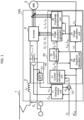
- FIG. 1 is a functional block diagram schematically showing the present device 10A according to a first embodiment.
- the present device 10A supplies electric power captured from the DC overhead line 1 to the induction motor 5.
- the present device 10A mainly includes an inverter 4, a filter circuit including a reactor 2 and a capacitor 3, a damping control unit 11, a vector control unit 20, and a variation detection unit 30.
- the reactor 2 is connected in series between the DC overhead line 1 and the DC side of the inverter 4 and the capacitor 3 is connected in parallel to the DC side of the inverter 4, which prevents an adverse effect that a harmonic current generated on the DC side of the inverter 4 flows out to the DC overhead line 1.
- the present device 10A of the first embodiment a case where the inverter 4 is combined with the induction motor 5 will be described, but a synchronous motor may be used after the configuration of the vector control unit is appropriately changed.
- torque control obtained by combining a chopper circuit with a DC electric motor may be performed.
- the present invention is useful even when a linear motor is used.
- the inverter 4 is a circuit that converts a DC voltage into a three-phase AC voltage having any frequency and any amplitude, and can perform both a power running operation of supplying electric power from the DC side to the AC side induction motor 5 and a regenerative operation of supplying electric power from the AC side induction motor 5 to the DC side.
- the variation detection unit 30 mainly includes a band-pass filter (BPF) 31 that extracts a variable component e cf of the capacitor voltage E cf .
- Phase lead compensation may be added to the characteristics of the band-pass filter 31 in consideration of an operation delay of the vector control unit 20.
- another filter such as a high-pass filter may be used instead of the band-pass filter, or when there is a known disturbance at a specific frequency, a characteristic of selectively blocking a component of the frequency may be used.
- the damping control unit 11 generates a damping manipulated variable ⁇ D * for suppressing the oscillation of the voltage E cf of the capacitor 3.
- the adder 12 adds the damping manipulated variable ⁇ D * output from the damping control unit to the torque command ⁇ 0 * received by the present device 10 from the host control system (not shown) in order to generate the driving force necessary for accelerating/decelerating the vehicle, and calculates a torque command ⁇ 1 * provided to the vector control unit 20.
- the vector control unit 20 operates the inverter 4 so that the torque ⁇ output from the induction motor 5 matches the torque command ⁇ 1 *.
- the vector control unit 20 performs control calculations in a rotating coordinate system including a d-axis in a direction matching the rotor interlinkage magnetic flux of the induction motor 5 and a q-axis orthogonal to the d-axis.
- the d-axis magnetic flux command ⁇ * 2d received from the host control system (not shown), the torque command ⁇ * 1 , the three-phase currents I U , I V , and I W flowing through the induction motor 5, and the rotational speed ⁇ r of the induction motor 5 are input to the vector control unit 20, and the vector control unit 20 outputs three-phase voltage commands V* U , V* V , and V* W obtained by calculating these to operate the inverter 4.
- the vector control unit 20 in FIG. 1 may be considered to include a torque control unit (not shown).
- the torque control unit generates voltage commands V* U , V* V , and V* W to be applied to the electric motor 5 according to the torque commands ⁇ 0 * and ⁇ 1 * or the current commands I* 1d and I** 1q .
- the torque control unit only needs to be a vector control system that generates the voltage commands V* U , V* V , and V* W so that the output torque ⁇ of the electric motor 5 or the current flowing through the electric motor 5 matches the torque commands ⁇ 0 * and ⁇ 1 * or the current commands I' 1d and I** 1q .
- the vector control unit 20 includes a current command calculation unit 21, a current control unit 22, a slip frequency calculation unit 23, a PWM waveform generator 25, a phase calculation unit 24, and a coordinate transformation unit 26.
- the vector control unit 20 may perform control using a value obtained by estimating the rotational speed ⁇ r of the induction motor 5 based on various pieces of information inside the vector control unit 20 such as the three-phase current flowing through the induction motor 5 and the terminal voltage of the induction motor 5.
- the current command calculation unit 21 generates a d-axis current command I* 1d and a q-axis current command I* 1q according to the following formulas (1) and (2) from a d-axis magnetic flux command ⁇ * 2d and a torque command ⁇ * 1 received from a host control system (not shown).
- s be a Laplace operator
- L 2 be a rotor self-inductance of the induction motor 5
- R 2 be a rotor resistance of the induction motor 5
- M a mutual inductance of the induction motor 5
- N p the number of pole pairs of the induction motor 5.
- I 1 d ⁇ 1 + s L 2 R 2 ⁇ 2 d ⁇ M 1
- I 1 q ⁇ ⁇ 1 ⁇ N p ⁇ 2 d ⁇ L 2 M 2
- the current control unit 22 generates a d-axis voltage command V d * and a q-axis voltage command V q * according to the following formulas (4) and (5) so that the d-axis current I 1d and the q-axis current I 1q respectively match the d-axis current command I* 1d and the q-axis current command I* 1q .
- L 1 be the stator self-inductance of the induction motor 5
- R 1 be the stator resistance of the induction motor 5
- ⁇ inv be the angular velocity of the three-phase AC voltage output from the inverter 4
- ⁇ acr be the response angular frequency of the current control unit 22.
- ⁇ is a leakage coefficient obtained by the following formula (3) from the circuit constant of the induction motor 56.
- the slip frequency calculation unit 23 estimates a slip frequency that is a difference between the rotation angular velocity of the rotor interlinkage magnetic flux of the induction motor 5 and the angular velocity ⁇ inv of the three-phase AC voltage, and outputs the slip frequency to the phase calculation unit 24.
- the phase calculation unit 24 calculates a phase angle ⁇ of the three-phase AC voltage output from the inverter 4.
- the phase calculation unit 24 calculates the phase angle ⁇ of the three-phase AC voltage according to the following formula (7) from the rotational speed ⁇ r of the induction motor 5 and the slip frequency estimated value ⁇ * s .
- ⁇ ⁇ ⁇ s ⁇ + ⁇ r dt
- the PWM waveform generator 25 outputs three-phase switching signals V* U , V* V , and V* W according to the phase angle ⁇ of the three-phase AC voltage output from the inverter 4, the d-axis voltage command V d *, and the q-axis voltage command V q *, and operates the inverter 4.
- the coordinate transformation unit 26 transforms the three-phase currents I U , I V , and I W flowing through the induction motor 5 into a d-axis current I 1d and a q-axis current I 1q in the rotating coordinate system by the following formula (8).
- Such an operation of the vector control unit 20 is a widely known technique as indirect vector control.
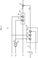
- FIG. 2 is a detailed control circuit diagram of the damping control unit 11 in FIG. 1 .
- the damping control unit 11 mainly includes a low-pass filter (LPF) 50 that extracts a DC component (with overline) E cf of the capacitor voltage E cf , an adder 51, a first manipulated variable calculation unit 60, and a second manipulated variable calculation unit 70.
- the first manipulated variable calculation unit 60 includes a divider 61 and a multiplier 62.
- the first manipulated variable calculation unit 60 calculates a value obtained by multiplying the torque command ⁇ * 0 by the variable component e cf of the capacitor voltage E cf and dividing the result by the DC component (with overline) E cf of the capacitor voltage E cf . This value is the first manipulated variable ⁇ * D1 .
- the second manipulated variable calculation unit 70 calculates a value obtained by multiplying the DC component (with overline) E cf of the capacitor voltage E cf , the variable component e cf of the capacitor voltage E cf , and the proportional constant 71 and dividing the product by the rotational speed ⁇ r of the induction motor 5. This value is the second manipulated variable ⁇ * D2 .
- the first manipulated variable ⁇ * D1 and the second manipulated variable ⁇ * D2 are added by the adder 51 to calculate the damping manipulated variable ⁇ * D .
- the proportional constant 71 multiplied in the second manipulated variable calculation unit 70 may be a constant value at all times or may be a variable value in consideration of an operation delay of the inverter 4 or the vector control unit 20.
- the second manipulated variable calculation unit 70 may switch the value of the proportional constant 71 depending on whether the inverter 4 performs the power running operation or the regenerative operation.
- the damping control unit 11 may use at least any one of the first manipulated variable ⁇ * D1 and the second manipulated variable ⁇ * D2 in a state of being disabled or both in an enabled state.
- the present device 10A can use the DC voltage as the DC component (with overline) E cf of the capacitor voltage E cf .
- Specific examples of this case include a case where the present device 10A receives DC electric power from a power conversion apparatus that performs voltage constant control instead of the DC overhead line 1.
- the resonance frequency of the filter circuit including the reactor 2 and the capacitor 3 to be subjected to the damping control is usually 10 Hz to 20 Hz, and thus the period thereof is about 50 to 100 ms.
- the speed of the vehicle does not change abruptly during such degree of time as the resonance period of the filter circuit.
- the torque command ⁇ * 0 received from the host control system does not change abruptly either. Therefore, hereinafter, for convenience of description, the rotational speed ⁇ r of the induction motor 5 and the torque command ⁇ * 0 can be treated as constant.
- damping control only needs to be performed in which the torque command ⁇ * 1 is operated according to the variable component e cf of the capacitor voltage E cf , the mechanical output ⁇ r ⁇ /N p of the induction motor 5 is varied, and the electric power P inv drawn from the DC side by the inverter 4 is varied.
- K D N p ⁇ r I ⁇ nv ⁇ + 2 ⁇ * N p C f L f E cf ⁇ ⁇ r
- the first term of the above formula (23) is proportional to the torque command ⁇ * 0 and the variable component e cf of the capacitor voltage E cf .
- the second term of the above formula (23) is inversely proportional to the rotational speed ⁇ r of the induction motor 5. These are grounds for calculating the first manipulated variable ⁇ * D1 and the second manipulated variable ⁇ * D2 to be calculated by the damping control unit 11.
- the first manipulated variable ⁇ * D1 is a value obtained by the first manipulated variable calculation unit 60 multiplying the torque command ⁇ * 0 by the variable component e cf of the capacitor voltage E cf and dividing the result by the DC component (with overline) E cf of the capacitor voltage E cf .
- the first manipulated variable ⁇ * D1 is calculated according to the torque commands ⁇ 0 * and ⁇ 1 * or the current commands I* 1d and I** 1q and the variable component e cf of the capacitor voltage E cf .
- the second manipulated variable ⁇ * D2 is a value obtained by the second manipulated variable calculation unit 70 multiplying the DC component (with overline) E cf of the capacitor voltage E cf , the variable component e cf of the capacitor voltage E cf , and the proportional constant 71 and dividing the product by the rotational speed ⁇ r of the induction motor 5.
- the second manipulated variable ⁇ * D2 is calculated according to the information on the rotational speed ⁇ r of the electric motor 5 and the variable component e cf of the capacitor voltage E cf .
- An object of the present device 10A is to obtain a constant damping characteristic with respect to the oscillation of the capacitor voltage E cf . Therefore, the present device 10A adds both the first manipulated variable and the second manipulated variable to the torque command ⁇ *0 . As a result, the present device 10A is not affected by any of the variable factors such as the voltage of the DC overhead line 1, the torque command ⁇ * 0 to the induction motor 5, and the rotational speed ⁇ r of the induction motor 5 with respect to the damping characteristic of the damping control.
- the present device 10A can obtain a constant damping characteristic that does not depend on the operating point of each of the conventional variable factors and can implement stable control. This is theoretically derived from the above formula (23).
- the present device 10A when the present device 10A is equipped under the floor of the vehicle, the restriction on the mounting position due to the weight balance inside the vehicle and between vehicles is relaxed, and the degree of freedom in designing the entire vehicle is improved.
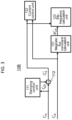
- FIG. 3 is a functional block diagram showing the present device 10B according to a second embodiment and shows only differences from the present device 10 in FIG. 1 . Therefore, the same reference numerals are used for common parts with the first embodiment in FIGS. 1 and 2 , and the description thereof will be omitted.
- the present device 10A according to the first embodiment receives the torque command ⁇ * 0 and the d-axis magnetic flux command ⁇ * 2d from a host control system (not shown), whereas the present device 10B according to the second embodiment receives the d-axis current command I* 1a and the q-axis current command I* 1q from a host control system (not shown).
- the damping control unit 11, the adder 12, the current command calculation unit 21, the current control unit 22, and the slip frequency calculation unit 23 in the first embodiment are replaced with a damping control unit 111, an adder 112, a magnetic flux command calculation unit 121, a current control unit 122, and a slip frequency calculation unit 123, respectively.
- the damping control unit 111 generates a damping manipulated variable I* qd for suppressing the oscillation of the voltage E cf of the capacitor 3.
- the adder 112 adds the damping manipulated variable I* qD output from the damping control unit to the q-axis current command I* 1q received from a host control system (not shown) by the present device 10A in order to generate the driving force necessary for accelerating/decelerating the vehicle, and calculates a q-axis current command I** 1q to be given to the vector control unit 20.
- the current control unit 122 generates a d-axis voltage command V d * and a q-axis voltage command V q * according to the following formulas (25) and (26) so that the d-axis current I 1d and the q-axis current I 1q respectively match the d-axis current command I* 1d and the q-axis current command I** 1q .
- V d * ⁇ acr ⁇ L 1 + ⁇ acr R 1 s I 1 d * ⁇ I 1 d ⁇ ⁇ inv ⁇ L 1 I 1 q * * 25
- V q * ⁇ acr ⁇ L 1 + ⁇ acr R 1 s I 1 q * * ⁇ I 1 q + ⁇ inv ⁇ L 1 I 1 d * + ⁇ inv M L 2 ⁇ 2 d * 26
- the slip frequency calculation unit 123 estimates a slip frequency that is a difference between the rotation angular velocity of the rotor interlinkage magnetic flux of the induction motor 5 and the angular velocity ⁇ inv of the three-phase AC voltage.
- the slip frequency calculation unit 123 generates a slip frequency estimated value ⁇ ' s according to the following formula (27) from the d-axis magnetic flux command ⁇ * 2d , the q-axis current command I** 1q , and the circuit constant of the induction motor 5.
- ⁇ s * R 2 MI 1 q * * L 2 ⁇ 2 d *
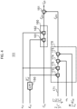
- FIG. 4 is a detailed control circuit diagram of the damping control unit 111 in FIG. 3 .
- the damping control unit 111 mainly includes a low-pass filter (LPF) 150 that extracts a DC component (with overline) E cf of the capacitor voltage E cf , an adder 151, a first manipulated variable calculation unit 160, and a second manipulated variable calculation unit 170.
- LPF low-pass filter
- a divider 161 and a multiplier 162 are provided.
- the first manipulated variable calculation unit 160 calculates a value obtained by multiplying the q-axis current command I* 1q by the variable component e cf of the capacitor voltage E cf and dividing the result by the DC component (with overline) E cf of the capacitor voltage E cf . This value is the first manipulated variable I* qD1 .
- the second manipulated variable calculation unit 170 calculates a value obtained by multiplying the DC component (with overline) E cf of the capacitor voltage E cf , the variable component e cf of the capacitor voltage E cf , and the proportional constant 171, dividing the product by the rotational speed ⁇ r of the induction motor 5, and further dividing the product by the d-axis magnetic flux command value M/L 2 ⁇ * 2d converted to stator reference. This value is the second manipulated variable I* qD2 .
- the second manipulated variable calculation unit 170 may calculate the second manipulated variable by performing division by the q-axis voltage command V q *, instead of division by the rotational speed ⁇ r of the induction motor 5 and the d-axis magnetic flux command value M/L 2 ⁇ * 2d converted to stator reference.
- the damping control unit 111 calculates the damping manipulated variable I* qD by adding the first manipulated variable I* qD1 and the second manipulated variable I* qD2 by the adder 151.
- FIG. 5 is a functional block diagram schematically showing a vehicular driving control device (the present device) 10C according to a third embodiment of the present invention and shows only differences from the present device in FIG. 1 . Therefore, the same reference numerals are used for common parts with the first embodiment in FIGS. 1 and 2 , and the description thereof will be omitted.
- the damping manipulated variable is added to the torque command ⁇ 0 *, and the result is provided to the vector control unit 20, whereas in the third embodiment, the damping manipulated variable is added to the q-axis voltage command V q *.
- the present device 10A in the first embodiment in FIG. 1 includes a damping control unit 11, an adder 12, a current command calculation unit 21, a current control unit 22, a slip frequency calculation unit 23, a phase calculation unit 24, and a PWM waveform generator 25.
- the present device 10C in the third embodiment in FIG. 5 includes a damping control unit 211, an adder 212, a current command calculation unit 221, a current control unit 222, a slip frequency calculation unit 223, a phase calculation unit 224, and a PWM waveform generator 225.
- the damping control unit 211 generates a damping manipulated variable V qD * for suppressing the oscillation of the voltage E cf of the capacitor 3.
- the adder 212 adds the damping manipulated variable V qD * to the q-axis voltage command V q * output from the current control unit 222, calculates a q-axis voltage command V q **, and gives the q-axis voltage command V q ** to the PWM waveform generator 225.
- the current control unit 122 generates a d-axis voltage command V d * and a q-axis voltage command V q * according to the above formulas (25) and (26) so that the d-axis current I 1d and the q-axis current I 1q respectively match the d-axis current command I* 1d and the q-axis current command I** 1q .
- the current control unit 222, the slip frequency calculation unit 223, and the phase calculation unit 224 in FIG. 5 are similar to the current control unit 22, the slip frequency calculation unit 23, and the phase calculation unit 24 in FIG. 1 , respectively.
- the PWM waveform generator 225 is similar to the PWM waveform generator 25 except that the q-axis voltage command V q ** is used instead of the q-axis voltage command V q *.
- FIG. 6 is a detailed control circuit diagram of the damping control unit 211 in FIG. 5 .
- the damping control unit 211 mainly includes a q-axis current manipulated variable calculation unit 250 and a multiplier 251.
- the q-axis current manipulated variable calculation unit 250 generates a q-axis current manipulated variable I* qD by the same configuration as the damping control unit 111.
- the multiplier 251 multiplies the q-axis current manipulated variable I* qD by the primary conversion resistor R ⁇ , obtained by substituting the circuit constant of the induction motor 5 into the following formula (28), to calculate the damping manipulated variable V qD **.
- R ⁇ R 1 + M L 2 2 R 2
- the calculation of the damping manipulated variable V qD * in the damping control unit 211 may be a simple multiplication by the multiplier 251 as in the third embodiment or may improve the transient responsiveness by, for example, adding the time derivative of the q-axis current manipulated variable I* qD .
- the damping control unit 211 calculates the damping manipulated variable V qD *, but may output the damping manipulated variable to be added to the d-axis voltage command V d * and give the damping manipulated variable to the PWM waveform generator 225 in consideration of electromagnetic interference of various amounts of the d-axis and the q-axis inside the induction motor 5.
- the damping manipulated variable to be added to the slip frequency estimated value ⁇ * s may be output and given to the phase calculation unit 224, or the damping manipulated variable to be added to the phase angle ⁇ of the three-phase AC voltage may be output and given to the PWM waveform generator 225.
- a compensation amount to be added to the d-axis current I 1d and the q-axis current I 1q may be calculated in the damping control unit 211 so that the operation of the current control unit 222 is not interfered, and the compensation amount may be given to the current control unit 222.
- the third embodiment is particularly useful because damping control is performed without depending on the response angular frequency ⁇ acr of the current control unit 222.
- FIG. 7 is a schematic circuit diagram of a variation detection unit 330 according to a fourth embodiment of the present invention and shows only differences from the variation detection unit 30 of the present device 10A in FIG. 1 . Therefore, the same reference numerals are used for common parts with the first embodiment in FIGS. 1 and 2 , and the description thereof will be omitted. While the variable component e cf of the capacitor voltage E cf is extracted from among the electrical quantity of the filter circuit in the first embodiment, the variable component i s of the reactor current I s is extracted from among the electrical quantity of the filter circuit in the fourth embodiment.
- the variation detection unit 30 in the first embodiment is replaced with a variation detection unit 330.
- the variation detection unit 330 mainly includes a band-pass filter (BPF) 331 that extracts a variable component i s of the reactor current I s .
- the band-pass filter 331 may have characteristics similar to those of the band-pass filter 31, or may have characteristics of converting the amplitude and phase of the variable component i s of the reactor current into values corresponding to the variable component e cf of the capacitor voltage E cf .
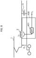
- FIG. 8 is a schematic circuit diagram of a variation detection unit 430 according to a fifth embodiment of the present invention and shows only differences from the variation detection unit 30 of the present device 10A in FIG. 1 . Therefore, the same reference numerals are used for common parts with the first embodiment shown in FIGS. 1 and 2 , and the description thereof will be omitted. While the variable component e cf of the capacitor voltage E cf is extracted from among the electrical quantity of the filter circuit in the first embodiment, the variable component v L of the reactor voltage V L is extracted from among the electrical quantity of the filter circuit in the fifth embodiment.
- the variation detection unit 30 in the first embodiment is replaced with a variation detection unit 430.
- the variation detection unit 430 mainly includes a band-pass filter (BPF) 431 that extracts a variable component v L of the reactor voltage V L .
- the band-pass filter 431 may have characteristics similar to those of the band-pass filter 31, or may have characteristics of converting the amplitude and phase of the variable component v L of the reactor voltage into values corresponding to the variable component e cf of the capacitor voltage E cf .
- FIG. 9 is a diagram showing only a portion different from that of the present device 10A of the first embodiment shown in FIG. 1 among the drive control device (present device) 10F according to the sixth embodiment. Description of parts common to the first embodiment will be omitted.
- the present device 10A of the first embodiment calculates the damping manipulated variable ⁇ * D by adding the first manipulated variable ⁇ * D1 and the second manipulated variable ⁇ * D2 by the adder 51.
- the present device 10F of the sixth embodiment acquires the damping manipulated variable ⁇ * D by referring to a table calculated in advance according to the first manipulated variable ⁇ * D1 and the second manipulated variable ⁇ * D2 .
- the present device 10F of the sixth embodiment replaces the adder 51 in the first embodiment shown in FIG. 1 with a table reference 551.
- the table reference 551 refers to the table data 552 according to the respective values of the first manipulated variable ⁇ * D1 and the second manipulated variable ⁇ * D2 .
- the present device 10F calculates the damping manipulated variable ⁇ * D to be output based on the reference value.
- the table data 552 may have any of a characteristic of simply adding the first manipulated variable ⁇ * D1 and the second manipulated variable, and a characteristic of limiting the value of the damping manipulated variable not to exceed a predetermined upper limit value or lower limit value.
- a plurality of types of table data 552 may be prepared and switched according to a section in which the vehicle travels. Alternatively, when a plurality of vehicles are connected and operated, a plurality of types of table data 552 may be switched according to the number and types of vehicles to be connected.
- the table reference 551 may perform simple linear interpolation processing on the table data 552, may perform interpolation processing such as higher order polynomial interpolation, or may not perform interpolation processing at all.
- the present device 10 can be summarized as follows.
- the filter circuit is interposed between the DC power source 1 and the DC side of the electric power conversion circuit 4.
- the filter circuit includes a reactor 2 and a capacitor 3, and prevents outflow of harmonics.
- the variation detection unit 30, 330, 430 detects a variable component e cf of the electrical quantity of the filter circuit.
- a torque control unit (not shown) is provided as a main function of the vector control unit 20 in FIG. 1 .
- the torque control unit generates voltage commands V* U , V* V , and V* W to be applied to the electric motor 5 according to the torque commands ⁇ 0 * and ⁇ 1 * or the current commands I' 1d and I** 1q .
- the electric power conversion circuit 4 converts the electric power of the DC power source 1 into three-phase AC according to the voltage commands V* U , V* V , and V* W , forms a desired rotating magnetic field, and supplies the rotating magnetic field to the electric motor 5.
- the damping control unit 11, 111, 211 suppresses the variable component e cf by operating the electric power conversion circuit 4 according to the damping manipulated variable ⁇ * D of the sum of the first manipulated variable ⁇ * D1 and the second manipulated variable ⁇ * D2 .
- the first manipulated variable ⁇ * D1 is calculated according to the torque commands ⁇ 0 * and ⁇ 1 * or the current commands I* 1d and I** 1q and the variable component e cf .
- the second manipulated variable ⁇ * D2 is calculated according to the rotational speed information of the electric motor 5 and the variable component e cf .
- the first term of the above formula (23) is proportional to the torque command ⁇ * 0 and the variable component e cf of the capacitor voltage E cf
- the second term of the above formula (23) is inversely proportional to the rotational speed ⁇ r of the induction motor 5.
- the present device 10 can implement damping control that provides constant damping to the oscillation of the capacitor voltage E cf .
- the constant damping provided by the damping control does not depend on the operating point such as the voltage of the DC overhead line 1, and the torque command ⁇ * 0 and the rotational speed ⁇ r of the induction motor 5.
- the present device 10 can implement stable damping control regardless of changes in the driving state of the vehicle and the voltage environment.
- the first is a reference value acquired according to the first manipulated variable ⁇ * D1 and the second manipulated variable ⁇ * D2 from the table data 552 calculated in advance.
- the second is an addition value of the first manipulated variable ⁇ * D1 and the second manipulated variable ⁇ * D2 as theoretically described based on the above formula (23).
- the present device 10 can easily implement ideal damping control by executing a program stored in a memory of a computer.
- the computer may be a one-chip microcomputer or a personal computer, and may also use a computer for other applications.
- the table data 552 stored in the memory is preferably updatable.
- the electrical quantity only needs to be at least any one of the following three types.
- the first is the basic form shown in FIGS. 1 and 2 , and the electrical quantity is the voltage E cf of the capacitor 3.
- the second electrical quantity is a current flowing through the reactor 2 as shown in FIG. 7 .
- the third electrical quantity is a voltage across the reactor 2 as shown in FIG. 8 .
- the variation detection unit 30, 330, 430 detects, at the shortest wiring distance, the oscillation phenomenon of the capacitor voltage E cf from the current of the reactor 2 which is the cause of the oscillation phenomenon of the capacitor voltage E cf , the voltage across the reactor 2, or the voltage E cf of the capacitor 3, more accurate damping control can be easily implemented.
- the first manipulated variable ⁇ * D1 acts in a direction of suppressing the variable component e cf .
- the first manipulated variable ⁇ * D1 is made proportional to the torque commands ⁇ 0 * and ⁇ 1 * or the current commands I* 1d and I** 1q and the variable component e cf .
- the vector control unit 20 can perform damping control in a direction of suppressing the magnitude of the variation cause, opposed to the magnitude of the variation cause.
- the present device 10 can perform damping control in a direction of suppressing the oscillation phenomenon itself of the capacitor voltage E cf .
- the second manipulated variable ⁇ * D2 only needs to be at least any one of the following three types.
- the first is made inversely proportional to the rotational speed information of the electric motor 5 also including a sensorless motor and is made proportional to the variable component e cf .
- the second is made inversely proportional to the voltage commands V* U , V* V , and V* W , and is made proportional to the variable component e cf .
- the third is made proportional to the DC component (with overline) E cf of the voltage E cf of the capacitor 3.
- the second manipulated variable calculation unit 70 may always set the proportional constant 71 used to calculate the second manipulated variable ⁇ * D2 to a constant value or may switch according to such a control delay in consideration of the operation delay of the inverter 4 and the vector control unit 20.
- the present device 10 described above can perform quick damping control with less control delay with respect to the oscillation of the capacitor voltage E cf .
- the electric motor 5 only needs to be the AC electric motor 5, and the electric power conversion circuit 4 only needs to be the inverter 4 that converts the voltage of the DC power source 1 into a three-phase AC voltage.
- the torque control unit only needs to be a vector control system that generates the voltage commands V* U , V* V , and V* W so that the output torque ⁇ of the electric motor 5 or the current flowing through the electric motor 5 matches the torque commands ⁇ 0 * and ⁇ 1 * or the current commands I* 1d and I** 1q .
- the present device 10 has good suitability, compatibility, and maintainability with conventional resources and conventional technologies, and thus is highly practical and easily maintains high performance.
Landscapes
- Engineering & Computer Science (AREA)
- Power Engineering (AREA)
- Transportation (AREA)
- Mechanical Engineering (AREA)
- Life Sciences & Earth Sciences (AREA)
- Sustainable Development (AREA)
- Sustainable Energy (AREA)
- Physics & Mathematics (AREA)
- Electromagnetism (AREA)
- Electric Propulsion And Braking For Vehicles (AREA)
- Control Of Ac Motors In General (AREA)
Abstract
Description
- The present invention relates to a vehicular driving control device and a method therefor.
- A technique for controlling the output torque of an electric motor is widely used in the industry. Also in an electric railway, a configuration in which torque control of an electric motor is performed by an inverter device using a DC overhead line as a power source is widely used.
- A DC railway vehicle (hereinafter, also referred to as a "vehicle") is generally provided with a filter circuit including a reactor and a capacitor in order to prevent an adverse effect that a harmonic current flows out from a DC side of the inverter device. However, it is known that the combination of the filter circuit and the inverter device causes an unstable resonance system, which causes the control of the electric motor to become unstable due to an oscillation phenomenon in which the capacitor voltage oscillates.
- The control for suppressing this oscillation phenomenon is the damping control, which is essential for the stable operation of the DC electric train. In addition, appropriately damping the oscillation of the capacitor voltage by the damping control is important for reducing the inductive obstacle due to the return current.
- PTL 1 shows a technique of calculating a variation rate of a capacitor voltage, operating a current command or a torque command of a vector control unit with a damping manipulated variable corresponding to the variation rate thereof, and with respect to the variation of the capacitor voltage, controlling a current of an inverter in a direction of suppressing the variation.
- PTL 1:
WO 2008/026249 - However, the damping control of PTL 1 has a problem in which the damping with respect to the variation of the capacitor voltage becomes strong when the torque command is large, and the damping becomes weak when the torque command is small. The present invention has been made in view of the above problems, and an object of the present invention is to provide a vehicular driving control device capable of performing damping control to apply constant damping to the oscillation of a capacitor voltage regardless of a voltage of a DC overhead line or an operating point of an electric motor.
- The present invention to solve the above problem is a vehicular driving control device including: an electric power conversion circuit connected to a DC power source, the electric power conversion circuit being configured to supply electric power of the DC power source to an electric motor according to a voltage command; a filter circuit interposed between a DC side of the electric power conversion circuit and the DC power source, the filter circuit including a reactor and a capacitor; a variation detection unit configured to detect a variable component of an electrical quantity related to the filter circuit; a torque control unit configured to generate the voltage command to be applied to the electric motor according to a torque command or a current command; and a damping control unit configured to operate the electric power conversion circuit to suppress the variable component. The damping control unit operates the electric power conversion circuit according to a damping manipulated variable based on: a first manipulated variable calculated according to the torque command or the current command and the variable component, and a second manipulated variable calculated according to rotational speed information of the electric motor and the variable component.
- According to the present invention, it is possible to provide a vehicular driving control device capable of performing damping control to provide constant damping to oscillation of a capacitor voltage regardless of a voltage of a DC overhead line or an operating point of an electric motor.
-
- [
FIG. 1] FIG. 1 is a functional block diagram schematically showing a vehicular driving control device (hereinafter, referred to as "the present device") 10A according to a first embodiment of the present invention. - [
FIG. 2] FIG. 2 is a detailed control circuit diagram of adamping control unit 11 inFIG. 1 . - [
FIG. 3] FIG. 3 is a functional block diagram showing a vehicular driving control device (this is also referred to as "the present device") 10B according to a second embodiment of the present invention. - [
FIG. 4] FIG. 4 is a detailed control circuit diagram of adamping control unit 111 inFIG. 3 . - [
FIG. 5] FIG. 5 is a functional block diagram schematically showing a vehicular driving control device (this is also referred to as "the present device") 10C according to a third embodiment of the present invention. - [
FIG. 6] FIG. 6 is a detailed control circuit diagram of adamping control unit 211 inFIG. 5 . - [
FIG. 7] FIG. 7 is a schematic circuit diagram of avariation detection unit 330 according to a fourth embodiment of the present invention. - [
FIG. 8] FIG. 8 is a schematic circuit diagram of avariation detection unit 430 according to a fifth embodiment of the present invention. - [
FIG. 9] FIG. 9 is a diagram showing only a part different from that of the first embodiment in a vehicular driving control device (this is also referred to as "the present device") 10F according to a sixth embodiment of the present invention. -
FIG. 1 is a functional block diagram schematically showing thepresent device 10A according to a first embodiment. Thepresent device 10A supplies electric power captured from the DC overhead line 1 to theinduction motor 5. Thepresent device 10A mainly includes aninverter 4, a filter circuit including areactor 2 and acapacitor 3, adamping control unit 11, avector control unit 20, and avariation detection unit 30. - It should be noted that, in addition to the
present device 10A of the first embodiment, the features of the respectivepresent devices 10B to 10F of the second to sixth embodiments will be described below, but when there is no need to distinguish, they are collectively referred to as the present device 10. Thereactor 2 is connected in series between the DC overhead line 1 and the DC side of theinverter 4 and thecapacitor 3 is connected in parallel to the DC side of theinverter 4, which prevents an adverse effect that a harmonic current generated on the DC side of theinverter 4 flows out to the DC overhead line 1. - In the
present device 10A of the first embodiment, a case where theinverter 4 is combined with theinduction motor 5 will be described, but a synchronous motor may be used after the configuration of the vector control unit is appropriately changed. In addition, torque control obtained by combining a chopper circuit with a DC electric motor may be performed. Furthermore, when the torque and the rotational speed in the following description are replaced with the thrust and the speed, the present invention is useful even when a linear motor is used. - The
inverter 4 is a circuit that converts a DC voltage into a three-phase AC voltage having any frequency and any amplitude, and can perform both a power running operation of supplying electric power from the DC side to the ACside induction motor 5 and a regenerative operation of supplying electric power from the ACside induction motor 5 to the DC side. - The
variation detection unit 30 mainly includes a band-pass filter (BPF) 31 that extracts a variable component ecf of the capacitor voltage Ecf. Phase lead compensation may be added to the characteristics of the band-pass filter 31 in consideration of an operation delay of thevector control unit 20. - In addition, another filter such as a high-pass filter may be used instead of the band-pass filter, or when there is a known disturbance at a specific frequency, a characteristic of selectively blocking a component of the frequency may be used.
- The
damping control unit 11 generates a damping manipulated variable τD* for suppressing the oscillation of the voltage Ecf of thecapacitor 3. Theadder 12 adds the damping manipulated variable τD* output from the damping control unit to the torque command τ0* received by the present device 10 from the host control system (not shown) in order to generate the driving force necessary for accelerating/decelerating the vehicle, and calculates a torque command τ1* provided to thevector control unit 20. - The
vector control unit 20 operates theinverter 4 so that the torque τ output from theinduction motor 5 matches the torque command τ1*. As well-known as vector control, thevector control unit 20 performs control calculations in a rotating coordinate system including a d-axis in a direction matching the rotor interlinkage magnetic flux of theinduction motor 5 and a q-axis orthogonal to the d-axis. - The d-axis magnetic flux command ϕ*2d received from the host control system (not shown), the torque command τ*1, the three-phase currents IU, IV, and IW flowing through the
induction motor 5, and the rotational speed ωr of theinduction motor 5 are input to thevector control unit 20, and thevector control unit 20 outputs three-phase voltage commands V*U, V*V, and V*W obtained by calculating these to operate theinverter 4. Thevector control unit 20 inFIG. 1 may be considered to include a torque control unit (not shown). - The torque control unit generates voltage commands V*U, V*V, and V*W to be applied to the
electric motor 5 according to the torque commands τ0* and τ1* or the current commands I*1d and I**1q. The torque control unit only needs to be a vector control system that generates the voltage commands V*U, V*V, and V*W so that the output torque τ of theelectric motor 5 or the current flowing through theelectric motor 5 matches the torque commands τ0* and τ1* or the current commands I'1d and I**1q. - The
vector control unit 20 includes a currentcommand calculation unit 21, acurrent control unit 22, a slipfrequency calculation unit 23, aPWM waveform generator 25, aphase calculation unit 24, and acoordinate transformation unit 26. - In the
vector control unit 20 of the first embodiment, a case where the rotational speed ωr of theinduction motor 5 is input thereto will be described, but the present invention is not limited thereto. Thevector control unit 20 may perform control using a value obtained by estimating the rotational speed ωr of theinduction motor 5 based on various pieces of information inside thevector control unit 20 such as the three-phase current flowing through theinduction motor 5 and the terminal voltage of theinduction motor 5. - Hereinafter, the configuration of the
vector control unit 20 will be described. The currentcommand calculation unit 21 generates a d-axis current command I*1d and a q-axis current command I*1q according to the following formulas (1) and (2) from a d-axis magnetic flux command ϕ*2d and a torque command τ*1 received from a host control system (not shown). Where let s be a Laplace operator, let L2 be a rotor self-inductance of theinduction motor 5, let R2 be a rotor resistance of theinduction motor 5, let M be a mutual inductance of theinduction motor 5, and let Np be the number of pole pairs of theinduction motor 5.
- The
current control unit 22 generates a d-axis voltage command Vd* and a q-axis voltage command Vq* according to the following formulas (4) and (5) so that the d-axis current I1d and the q-axis current I1q respectively match the d-axis current command I*1d and the q-axis current command I*1q. - Where let L1 be the stator self-inductance of the
induction motor 5, let R1 be the stator resistance of theinduction motor 5, let ωinv be the angular velocity of the three-phase AC voltage output from theinverter 4, and let ωacr be the response angular frequency of thecurrent control unit 22. In addition, σ is a leakage coefficient obtained by the following formula (3) from the circuit constant of the induction motor 56.
- In order to match the direction of the d-axis with the direction of the rotor interlinkage magnetic flux of the
induction motor 5, the slipfrequency calculation unit 23 estimates a slip frequency that is a difference between the rotation angular velocity of the rotor interlinkage magnetic flux of theinduction motor 5 and the angular velocity ωinv of the three-phase AC voltage, and outputs the slip frequency to thephase calculation unit 24. The slipfrequency calculation unit 23 calculates a slip frequency estimated value ω*s according to the following formula (6) from the d-axis magnetic flux command ϕ*2d, the q-axis current command I*1q, and the circuit constant of theinduction motor 5.
[Mathematical 3]
- The
phase calculation unit 24 calculates a phase angle θ of the three-phase AC voltage output from theinverter 4. Thephase calculation unit 24 calculates the phase angle θ of the three-phase AC voltage according to the following formula (7) from the rotational speed ωr of theinduction motor 5 and the slip frequency estimated value ω*s.
[Mathematical 4]
- The
PWM waveform generator 25 outputs three-phase switching signals V*U, V*V, and V*W according to the phase angle θ of the three-phase AC voltage output from theinverter 4, the d-axis voltage command Vd*, and the q-axis voltage command Vq*, and operates theinverter 4. The coordinatetransformation unit 26 transforms the three-phase currents IU, IV, and IW flowing through theinduction motor 5 into a d-axis current I1d and a q-axis current I1q in the rotating coordinate system by the following formula (8). Such an operation of thevector control unit 20 is a widely known technique as indirect vector control.
[Mathematical 5]
-
FIG. 2 is a detailed control circuit diagram of the dampingcontrol unit 11 inFIG. 1 . The dampingcontrol unit 11 mainly includes a low-pass filter (LPF) 50 that extracts a DC component (with overline) Ecf of the capacitor voltage Ecf, anadder 51, a first manipulatedvariable calculation unit 60, and a second manipulatedvariable calculation unit 70. The first manipulatedvariable calculation unit 60 includes adivider 61 and amultiplier 62. - The first manipulated
variable calculation unit 60 calculates a value obtained by multiplying the torque command τ*0 by the variable component ecf of the capacitor voltage Ecf and dividing the result by the DC component (with overline) Ecf of the capacitor voltage Ecf. This value is the first manipulated variable τ*D1. The second manipulatedvariable calculation unit 70 calculates a value obtained by multiplying the DC component (with overline) Ecf of the capacitor voltage Ecf, the variable component ecf of the capacitor voltage Ecf, and the proportional constant 71 and dividing the product by the rotational speed ωr of theinduction motor 5. This value is the second manipulated variable τ*D2. - The first manipulated variable τ*D1 and the second manipulated variable τ*D2 are added by the
adder 51 to calculate the damping manipulated variable τ*D. The proportional constant 71 multiplied in the second manipulatedvariable calculation unit 70 may be a constant value at all times or may be a variable value in consideration of an operation delay of theinverter 4 or thevector control unit 20. - In addition, the second manipulated
variable calculation unit 70 may switch the value of the proportional constant 71 depending on whether theinverter 4 performs the power running operation or the regenerative operation. In addition, the dampingcontrol unit 11 may use at least any one of the first manipulated variable τ*D1 and the second manipulated variable τ*D2 in a state of being disabled or both in an enabled state. - When the DC voltage is known, the
present device 10A can use the DC voltage as the DC component (with overline) Ecf of the capacitor voltage Ecf. Specific examples of this case include a case where thepresent device 10A receives DC electric power from a power conversion apparatus that performs voltage constant control instead of the DC overhead line 1. - Before the description of the effect of the first embodiment, the principle of occurrence of the oscillation phenomenon of the capacitor voltage Ecf and the theoretical basis of the oscillation suppression by the configuration of the first embodiment will be described. The resonance frequency of the filter circuit including the
reactor 2 and thecapacitor 3 to be subjected to the damping control is usually 10 Hz to 20 Hz, and thus the period thereof is about 50 to 100 ms. - The speed of the vehicle does not change abruptly during such degree of time as the resonance period of the filter circuit. In addition, during the same degree of time, the torque command τ*0 received from the host control system does not change abruptly either. Therefore, hereinafter, for convenience of description, the rotational speed ωr of the
induction motor 5 and the torque command τ*0 can be treated as constant. - Here, when the torque command τ*0 and the torque command τ*1 are equal without performing damping control at all, and furthermore, the output torque τ of the
induction motor 5 matches the torque command τ*1 by vector control, let the number of pole pairs of theinduction motor 5 be Np, the mechanical output ωrτ/Np of theinduction motor 5 is also constant. Ignoring losses inside thepresent device 10A and theinduction motor 5, the electric power Pinv drawn from the DC side by theinverter 4 is equal to the mechanical output ωrτ/Np of theinduction motor 5, and thus this is also constant, and the following formula (9) holds.
[Mathematical 6]
- Let the current drawn from the DC side by the
inverter 4 be Iinv, the following formula (10) holds.
[Mathematical 7]
- When the ratio of the variable component iinv of Iinv to the variable component ecf of the capacitor voltage Ecf is obtained based on the above formulas (9) and (10), the following formula (11) is obtained. However, the DC component of the current drawn from the DC side by the
inverter 4 was defined as (with overline) Iinv.
[Mathematical 8]
- Here, when a closed-loop transfer function from the variable component es of the voltage of the DC overhead line 1 to the variable component ecf of the capacitor voltage Ecf is obtained, a transfer function of a secondary system as in the following formula (12) is obtained.
[Mathematical 9]
- When this is rewritten using the resonance angular frequency ωn and the damping coefficient ζ of the filter circuit, the following formula (13) is obtained.
[Mathematical 10]
- By comparing the first-order coefficient of s among the denominators of the above formulas (12) and (13), the following is obtained.
[Mathematical 11]
- It is generally known that the oscillation phenomenon of the secondary system decays when the damping coefficient ζ is positive, remains sustained when the damping coefficient ζ is 0, and expands when the damping coefficient ζ is negative. Therefore, when the
induction motor 5 performs the power running operation and the (with overline) Iinv becomes positive, the damping coefficient ζ becomes negative, and the oscillation of the capacitor voltage Ecf expands with time, leading to unstable control. - To prevent this phenomenon, control such that iinv/ecf becomes positive only needs to be implemented, and the damping coefficient ζ only needs to be set to a positive value. That is, damping control only needs to be performed in which the torque command τ*1 is operated according to the variable component ecf of the capacitor voltage Ecf, the mechanical output ωrτ/Np of the
induction motor 5 is varied, and the electric power Pinv drawn from the DC side by theinverter 4 is varied. - Based on the above, what damping control is necessary is derived in order to make the damping coefficient ζ of the oscillation of the capacitor voltage Ecf coincide with a desired positive value ζ*, and the theoretical basis of the oscillation suppression according to the first embodiment is shown.
- Let a variation amount of the output torque τ of the
induction motor 5 by the damping control be τD, and it is assumed that the variation amount is in a proportional relationship with the variable component ecf of the capacitor voltage Ecf. Let this proportional constant be KD, and the following formula (15) holds.
[Mathematical 12]
- After ignoring the loss inside the present device 10 and the
induction motor 5, when the component pinvD that varies by the damping control in the electric power Pinv drawn from the DC side by theinverter 4 is obtained, the following formula (16) is obtained. Using this, when the ratio of the variable component iinv of Iinv to the variable component ecf of Ecf is obtained, the following formula (17) is obtained.
- Using the above formula (17), when a closed-loop transfer function from the variable component es of the voltage of the DC overhead line 1 to the variable component ecf of the capacitor voltage Ecf is obtained, a transfer function of a secondary system as the following formula (18) is obtained.
[Mathematical 14]
- When the damping coefficient ζ of this secondary system coincides with a desired positive value ζ*, the following formula (19) holds.
[Mathematical 15]
- When the proportional constant KD is arranged, the following formula (20) is obtained.
[Mathematical 16]
- Ignoring losses inside the present device 10 and the
induction motor 5, the DC component of the electric power Pinv drawn from the DC side by theinverter 4 and the DC component of the mechanical output ωrτ/Np of theinduction motor 5 coincide with each other. That is, the following formula (21) holds.
[Mathematical 17]
- When the proportional constant KD is obtained using the above formula (21), the following formula (22) is obtained.
[Mathematical 18]
- When the variation amount τD of the output torque τ of the
induction motor 5 by the damping control is obtained using the above formulas (15) and (22), the following formula (23) is obtained. The object of thepresent device 10A can be achieved by varying the output torque τ of theinduction motor 5 according to the variation amount τD of the following formula (23).
[Mathematical 19]
- The first term of the above formula (23) is proportional to the torque command τ*0 and the variable component ecf of the capacitor voltage Ecf. The second term of the above formula (23) is inversely proportional to the rotational speed ωr of the
induction motor 5. These are grounds for calculating the first manipulated variable τ*D1 and the second manipulated variable τ*D2 to be calculated by the dampingcontrol unit 11. - The first manipulated variable τ*D1 is a value obtained by the first manipulated
variable calculation unit 60 multiplying the torque command τ*0 by the variable component ecf of the capacitor voltage Ecf and dividing the result by the DC component (with overline) Ecf of the capacitor voltage Ecf. In other words, the first manipulated variable τ*D1 is calculated according to the torque commands τ0* and τ1* or the current commands I*1d and I**1q and the variable component ecf of the capacitor voltage Ecf. - The second manipulated variable τ*D2 is a value obtained by the second manipulated
variable calculation unit 70 multiplying the DC component (with overline) Ecf of the capacitor voltage Ecf, the variable component ecf of the capacitor voltage Ecf, and the proportional constant 71 and dividing the product by the rotational speed ωr of theinduction motor 5. In other words, the second manipulated variable τ*D2 is calculated according to the information on the rotational speed ωr of theelectric motor 5 and the variable component ecf of the capacitor voltage Ecf. - An object of the
present device 10A is to obtain a constant damping characteristic with respect to the oscillation of the capacitor voltage Ecf. Therefore, thepresent device 10A adds both the first manipulated variable and the second manipulated variable to the torque command τ*0. As a result, thepresent device 10A is not affected by any of the variable factors such as the voltage of the DC overhead line 1, the torque command τ*0 to theinduction motor 5, and the rotational speed ωr of theinduction motor 5 with respect to the damping characteristic of the damping control. - That is, the
present device 10A can obtain a constant damping characteristic that does not depend on the operating point of each of the conventional variable factors and can implement stable control. This is theoretically derived from the above formula (23). As described above, according to thepresent device 10A of the first embodiment, it is possible to obtain a constant damping characteristic with respect to the oscillation of the capacitor voltage Ecf without depending on the operating point such as the voltage of the DC overhead line 1 and the torque and rotational speed ωr output from theinduction motor 5. Accordingly, in the electric railway to which thepresent device 10A is applied, since it is possible to reduce the inductive obstacle due to the return current, it is possible to reduce the size and weight of thereactor 2 and thecapacitor 3 used for the filter circuit. - Furthermore, accordingly, when the
present device 10A is equipped under the floor of the vehicle, the restriction on the mounting position due to the weight balance inside the vehicle and between vehicles is relaxed, and the degree of freedom in designing the entire vehicle is improved. -
FIG. 3 is a functional block diagram showing thepresent device 10B according to a second embodiment and shows only differences from the present device 10 inFIG. 1 . Therefore, the same reference numerals are used for common parts with the first embodiment inFIGS. 1 and2 , and the description thereof will be omitted. Thepresent device 10A according to the first embodiment receives the torque command τ*0 and the d-axis magnetic flux command Φ*2d from a host control system (not shown), whereas thepresent device 10B according to the second embodiment receives the d-axis current command I*1a and the q-axis current command I*1q from a host control system (not shown). - The damping
control unit 11, theadder 12, the currentcommand calculation unit 21, thecurrent control unit 22, and the slipfrequency calculation unit 23 in the first embodiment are replaced with a dampingcontrol unit 111, anadder 112, a magnetic fluxcommand calculation unit 121, acurrent control unit 122, and a slipfrequency calculation unit 123, respectively. The magnetic fluxcommand calculation unit 121 calculates a d-axis magnetic flux command Φ*2d according to the following formula (24) from the d-axis current command I*1d and the circuit constant of theinduction motor 5.
[Mathematical 20]
- The damping
control unit 111 generates a damping manipulated variable I*qd for suppressing the oscillation of the voltage Ecf of thecapacitor 3. Theadder 112 adds the damping manipulated variable I*qD output from the damping control unit to the q-axis current command I*1q received from a host control system (not shown) by thepresent device 10A in order to generate the driving force necessary for accelerating/decelerating the vehicle, and calculates a q-axis current command I**1q to be given to thevector control unit 20. - The
current control unit 122 generates a d-axis voltage command Vd* and a q-axis voltage command Vq* according to the following formulas (25) and (26) so that the d-axis current I1d and the q-axis current I1q respectively match the d-axis current command I*1d and the q-axis current command I**1q.
- In order to match the direction of the d-axis with the direction of the rotor interlinkage magnetic flux of the
induction motor 5, the slipfrequency calculation unit 123 estimates a slip frequency that is a difference between the rotation angular velocity of the rotor interlinkage magnetic flux of theinduction motor 5 and the angular velocity ωinv of the three-phase AC voltage. The slipfrequency calculation unit 123 generates a slip frequency estimated value ω's according to the following formula (27) from the d-axis magnetic flux command Φ*2d, the q-axis current command I**1q, and the circuit constant of theinduction motor 5.
[Mathematical 22]
-
FIG. 4 is a detailed control circuit diagram of the dampingcontrol unit 111 inFIG. 3 . The dampingcontrol unit 111 mainly includes a low-pass filter (LPF) 150 that extracts a DC component (with overline) Ecf of the capacitor voltage Ecf, anadder 151, a first manipulatedvariable calculation unit 160, and a second manipulatedvariable calculation unit 170. Adivider 161 and amultiplier 162 are provided. - The first manipulated
variable calculation unit 160 calculates a value obtained by multiplying the q-axis current command I*1q by the variable component ecf of the capacitor voltage Ecf and dividing the result by the DC component (with overline) Ecf of the capacitor voltage Ecf. This value is the first manipulated variable I*qD1. The second manipulatedvariable calculation unit 170 calculates a value obtained by multiplying the DC component (with overline) Ecf of the capacitor voltage Ecf, the variable component ecf of the capacitor voltage Ecf, and theproportional constant 171, dividing the product by the rotational speed ωr of theinduction motor 5, and further dividing the product by the d-axis magnetic flux command value M/L2Φ*2d converted to stator reference. This value is the second manipulated variable I*qD2. - The second manipulated
variable calculation unit 170 may calculate the second manipulated variable by performing division by the q-axis voltage command Vq*, instead of division by the rotational speed ωr of theinduction motor 5 and the d-axis magnetic flux command value M/L2Φ*2d converted to stator reference. The dampingcontrol unit 111 calculates the damping manipulated variable I*qD by adding the first manipulated variable I*qD1 and the second manipulated variable I*qD2 by theadder 151. - In the drive control device, when the vector control of the
induction motor 5 is established, it is generally known that the q-axis current I1q and the output torque τ of theinduction motor 5 have a proportional relationship. Therefore, also when the damping manipulated variable is added to the q-axis current command I*1q in the second embodiment, the same effect as that of the first embodiment can be obtained. -
FIG. 5 is a functional block diagram schematically showing a vehicular driving control device (the present device) 10C according to a third embodiment of the present invention and shows only differences from the present device inFIG. 1 . Therefore, the same reference numerals are used for common parts with the first embodiment inFIGS. 1 and2 , and the description thereof will be omitted. In the first embodiment, the damping manipulated variable is added to the torque command τ0*, and the result is provided to thevector control unit 20, whereas in the third embodiment, the damping manipulated variable is added to the q-axis voltage command Vq*. - The
present device 10A in the first embodiment inFIG. 1 includes a dampingcontrol unit 11, anadder 12, a currentcommand calculation unit 21, acurrent control unit 22, a slipfrequency calculation unit 23, aphase calculation unit 24, and aPWM waveform generator 25. As these are correspondingly replaced, thepresent device 10C in the third embodiment inFIG. 5 includes a dampingcontrol unit 211, anadder 212, a currentcommand calculation unit 221, acurrent control unit 222, a slipfrequency calculation unit 223, aphase calculation unit 224, and aPWM waveform generator 225. - The damping
control unit 211 generates a damping manipulated variable VqD* for suppressing the oscillation of the voltage Ecf of thecapacitor 3. Theadder 212 adds the damping manipulated variable VqD* to the q-axis voltage command Vq* output from thecurrent control unit 222, calculates a q-axis voltage command Vq**, and gives the q-axis voltage command Vq** to thePWM waveform generator 225. - The
current control unit 122 generates a d-axis voltage command Vd* and a q-axis voltage command Vq* according to the above formulas (25) and (26) so that the d-axis current I1d and the q-axis current I1q respectively match the d-axis current command I*1d and the q-axis current command I**1q. Thecurrent control unit 222, the slipfrequency calculation unit 223, and thephase calculation unit 224 inFIG. 5 are similar to thecurrent control unit 22, the slipfrequency calculation unit 23, and thephase calculation unit 24 inFIG. 1 , respectively. ThePWM waveform generator 225 is similar to thePWM waveform generator 25 except that the q-axis voltage command Vq** is used instead of the q-axis voltage command Vq*. -
FIG. 6 is a detailed control circuit diagram of the dampingcontrol unit 211 inFIG. 5 . The dampingcontrol unit 211 mainly includes a q-axis current manipulatedvariable calculation unit 250 and amultiplier 251. The q-axis current manipulatedvariable calculation unit 250 generates a q-axis current manipulated variable I*qD by the same configuration as the dampingcontrol unit 111. Themultiplier 251 multiplies the q-axis current manipulated variable I*qD by the primary conversion resistor Rσ, obtained by substituting the circuit constant of theinduction motor 5 into the following formula (28), to calculate the damping manipulated variable VqD**.
[Mathematical 23]
- The calculation of the damping manipulated variable VqD* in the damping
control unit 211 may be a simple multiplication by themultiplier 251 as in the third embodiment or may improve the transient responsiveness by, for example, adding the time derivative of the q-axis current manipulated variable I*qD. - In the third embodiment, the damping
control unit 211 calculates the damping manipulated variable VqD*, but may output the damping manipulated variable to be added to the d-axis voltage command Vd* and give the damping manipulated variable to thePWM waveform generator 225 in consideration of electromagnetic interference of various amounts of the d-axis and the q-axis inside theinduction motor 5. - In addition, in consideration of the influence of the damping control on the slip frequency of the
induction motor 5, the damping manipulated variable to be added to the slip frequency estimated value ω*s may be output and given to thephase calculation unit 224, or the damping manipulated variable to be added to the phase angle θ of the three-phase AC voltage may be output and given to thePWM waveform generator 225. Furthermore, in consideration of the influence of the damping control on the d-axis current I1d and the q-axis current I1q, a compensation amount to be added to the d-axis current I1d and the q-axis current I1q may be calculated in the dampingcontrol unit 211 so that the operation of thecurrent control unit 222 is not interfered, and the compensation amount may be given to thecurrent control unit 222. - Even when the damping manipulated variable is added to the q-axis voltage command Vq* as in the third embodiment, if the change amount of the q-axis current I1q caused by the damping manipulated variable VqD* matches the q-axis current manipulated variable I*qD, the same effect as in the first embodiment can be obtained by the same principle as in the second embodiment.
- In the first embodiment and the second embodiment, when the response angular frequency ωacr of the
current control unit 22 and thecurrent control unit 122 is not sufficiently higher than the resonance angular frequency ωn of the filter circuit, the response delay of the output torque τ of theinduction motor 5 cannot be ignored, and it may be difficult to secure control stability. In such a case, the third embodiment is particularly useful because damping control is performed without depending on the response angular frequency ωacr of thecurrent control unit 222. -
FIG. 7 is a schematic circuit diagram of avariation detection unit 330 according to a fourth embodiment of the present invention and shows only differences from thevariation detection unit 30 of thepresent device 10A inFIG. 1 . Therefore, the same reference numerals are used for common parts with the first embodiment inFIGS. 1 and2 , and the description thereof will be omitted. While the variable component ecf of the capacitor voltage Ecf is extracted from among the electrical quantity of the filter circuit in the first embodiment, the variable component is of the reactor current Is is extracted from among the electrical quantity of the filter circuit in the fourth embodiment. - The
variation detection unit 30 in the first embodiment is replaced with avariation detection unit 330. Thevariation detection unit 330 mainly includes a band-pass filter (BPF) 331 that extracts a variable component is of the reactor current Is. The band-pass filter 331 may have characteristics similar to those of the band-pass filter 31, or may have characteristics of converting the amplitude and phase of the variable component is of the reactor current into values corresponding to the variable component ecf of the capacitor voltage Ecf. -
FIG. 8 is a schematic circuit diagram of avariation detection unit 430 according to a fifth embodiment of the present invention and shows only differences from thevariation detection unit 30 of thepresent device 10A inFIG. 1 . Therefore, the same reference numerals are used for common parts with the first embodiment shown inFIGS. 1 and2 , and the description thereof will be omitted. While the variable component ecf of the capacitor voltage Ecf is extracted from among the electrical quantity of the filter circuit in the first embodiment, the variable component vL of the reactor voltage VL is extracted from among the electrical quantity of the filter circuit in the fifth embodiment. - The
variation detection unit 30 in the first embodiment is replaced with avariation detection unit 430. Thevariation detection unit 430 mainly includes a band-pass filter (BPF) 431 that extracts a variable component vL of the reactor voltage VL. The band-pass filter 431 may have characteristics similar to those of the band-pass filter 31, or may have characteristics of converting the amplitude and phase of the variable component vL of the reactor voltage into values corresponding to the variable component ecf of the capacitor voltage Ecf. -
FIG. 9 is a diagram showing only a portion different from that of thepresent device 10A of the first embodiment shown inFIG. 1 among the drive control device (present device) 10F according to the sixth embodiment. Description of parts common to the first embodiment will be omitted. Thepresent device 10A of the first embodiment calculates the damping manipulated variable τ*D by adding the first manipulated variable τ*D1 and the second manipulated variable τ*D2 by theadder 51. On the other hand, thepresent device 10F of the sixth embodiment acquires the damping manipulated variable τ*D by referring to a table calculated in advance according to the first manipulated variable τ*D1 and the second manipulated variable τ*D2. - The
present device 10F of the sixth embodiment replaces theadder 51 in the first embodiment shown inFIG. 1 with atable reference 551. Thetable reference 551 refers to thetable data 552 according to the respective values of the first manipulated variable τ*D1 and the second manipulated variable τ*D2. Thepresent device 10F calculates the damping manipulated variable τ*D to be output based on the reference value. Thetable data 552 may have any of a characteristic of simply adding the first manipulated variable τ*D1 and the second manipulated variable, and a characteristic of limiting the value of the damping manipulated variable not to exceed a predetermined upper limit value or lower limit value. - In addition, a plurality of types of
table data 552 may be prepared and switched according to a section in which the vehicle travels. Alternatively, when a plurality of vehicles are connected and operated, a plurality of types oftable data 552 may be switched according to the number and types of vehicles to be connected. Thetable reference 551 may perform simple linear interpolation processing on thetable data 552, may perform interpolation processing such as higher order polynomial interpolation, or may not perform interpolation processing at all. - The present device 10 can be summarized as follows.
- [1] The present device 10 is a vehicular driving control device 10 that drives the
electric motor 5 by controlling the electricpower conversion circuit 4 connected to the DC power source 1 by thevector control unit 20. The present device 10 includes a filter circuit, avariation detection unit power conversion circuit 4, and a dampingcontrol unit - The filter circuit is interposed between the DC power source 1 and the DC side of the electric
power conversion circuit 4. The filter circuit includes areactor 2 and acapacitor 3, and prevents outflow of harmonics. Thevariation detection unit vector control unit 20 inFIG. 1 . The torque control unit generates voltage commands V*U, V*V, and V*W to be applied to theelectric motor 5 according to the torque commands τ0* and τ1* or the current commands I'1d and I**1q. - The electric
power conversion circuit 4 converts the electric power of the DC power source 1 into three-phase AC according to the voltage commands V*U, V*V, and V*W, forms a desired rotating magnetic field, and supplies the rotating magnetic field to theelectric motor 5. As shown in the above formula (23), the dampingcontrol unit power conversion circuit 4 according to the damping manipulated variable τ*D of the sum of the first manipulated variable τ*D1 and the second manipulated variable τ*D2. - As indicated by τ*D1 before the
addition processing 51 inFIG. 2 , the first manipulated variable τ*D1 is calculated according to the torque commands τ0* and τ1* or the current commands I*1d and I**1q and the variable component ecf. As indicated by τ*D2 before theaddition processing 51 inFIG. 2 , the second manipulated variable τ*D2 is calculated according to the rotational speed information of theelectric motor 5 and the variable component ecf. - The first term of the above formula (23) is proportional to the torque command τ*0 and the variable component ecf of the capacitor voltage Ecf, and the second term of the above formula (23) is inversely proportional to the rotational speed ωr of the
induction motor 5. These are the first manipulated variable τ*D1 and the second manipulated variable τ*D2 to be calculated by the dampingcontrol unit 11. - That is, by adding both the first manipulated variable τ*D1 and the second manipulated variable τ*D2 to the torque command τ*0, the present device 10 can implement damping control that provides constant damping to the oscillation of the capacitor voltage Ecf. The constant damping provided by the damping control does not depend on the operating point such as the voltage of the DC overhead line 1, and the torque command τ*0 and the rotational speed ωr of the
induction motor 5. As a result, the present device 10 can implement stable damping control regardless of changes in the driving state of the vehicle and the voltage environment. - [2] In the above [1], a numerical value generated by at least any one of the following only needs to be used as the damping manipulated variable τ*D. As shown in
FIG. 9 , the first is a reference value acquired according to the first manipulated variable τ*D1 and the second manipulated variable τ*D2 from thetable data 552 calculated in advance. The second is an addition value of the first manipulated variable τ*D1 and the second manipulated variable τ*D2 as theoretically described based on the above formula (23). - The present device 10 can easily implement ideal damping control by executing a program stored in a memory of a computer. It should be noted that the computer may be a one-chip microcomputer or a personal computer, and may also use a computer for other applications. In addition, the
table data 552 stored in the memory is preferably updatable. - [3] In the above [1], the electrical quantity only needs to be at least any one of the following three types. The first is the basic form shown in
FIGS. 1 and2 , and the electrical quantity is the voltage Ecf of thecapacitor 3. The second electrical quantity is a current flowing through thereactor 2 as shown inFIG. 7 . The third electrical quantity is a voltage across thereactor 2 as shown inFIG. 8 . In the present device 10 as described above, since thevariation detection unit reactor 2 which is the cause of the oscillation phenomenon of the capacitor voltage Ecf, the voltage across thereactor 2, or the voltage Ecf of thecapacitor 3, more accurate damping control can be easily implemented. - [4] In the above [1], if the first manipulated variable τ*D1 is at least any one of the following two types, the first manipulated variable τ*D1 acts in a direction of suppressing the variable component ecf. First, the first manipulated variable τ*D1 is made proportional to the torque commands τ0* and τ1* or the current commands I*1d and I**1q and the variable component ecf. As a result, the
vector control unit 20 can perform damping control in a direction of suppressing the magnitude of the variation cause, opposed to the magnitude of the variation cause. Second, as shown in thedivision processing 61 inFIG. 2 , the first manipulated variable τ*D1 is made inversely proportional to the DC component (with overline) Ecf of the voltage Ecf of thecapacitor 3. As a result, the present device 10 can perform damping control in a direction of suppressing the oscillation phenomenon itself of the capacitor voltage Ecf. - [5] In the above [1], as shown in the
multiplication processing 72 inFIG. 2 , the second manipulated variable τ*D2 only needs to be at least any one of the following three types. The first is made inversely proportional to the rotational speed information of theelectric motor 5 also including a sensorless motor and is made proportional to the variable component ecf. The second is made inversely proportional to the voltage commands V*U, V*V, and V*W, and is made proportional to the variable component ecf. The third is made proportional to the DC component (with overline) Ecf of the voltage Ecf of thecapacitor 3. In the present device 10 as described above, as the rotational speed is lower, the voltage commands V*U, V*V, and V*W are smaller, and the oscillation and the variation cause of the capacitor voltage Ecf are larger, thevector control unit 20 exhibits a larger influence of the variation. Therefore, damping control can be performed in a direction of suppressing the magnitude as opposed to the magnitude thereof. - [6] In the above [1], the second manipulated
variable calculation unit 70 may always set the proportional constant 71 used to calculate the second manipulated variable τ*D2 to a constant value or may switch according to such a control delay in consideration of the operation delay of theinverter 4 and thevector control unit 20. The present device 10 described above can perform quick damping control with less control delay with respect to the oscillation of the capacitor voltage Ecf. - [7] In the above [1] to [6], the
electric motor 5 only needs to be the ACelectric motor 5, and the electricpower conversion circuit 4 only needs to be theinverter 4 that converts the voltage of the DC power source 1 into a three-phase AC voltage. Furthermore, the torque control unit only needs to be a vector control system that generates the voltage commands V*U, V*V, and V*W so that the output torque τ of theelectric motor 5 or the current flowing through theelectric motor 5 matches the torque commands τ0* and τ1* or the current commands I*1d and I**1q. The present device 10 has good suitability, compatibility, and maintainability with conventional resources and conventional technologies, and thus is highly practical and easily maintains high performance. -
- 1 DC overhead line (DC power source)
- 2 reactor
- 3 capacitor
- 4 inverter
- 5
induction motor 5 - 10 vehicular driving control device (the present device)
- 11, 111, 211 damping control unit
- 12, 112, 212 adder
- 20 vector control unit
- 21, 221 current command calculation unit
- 121 magnetic flux command calculation unit
- 22,122, 222 current control unit
- 23,123, 223 slip frequency calculation unit
- 24, 224 phase calculation unit
- 25, 225 PWM waveform generator
- 26 coordinate transformation unit
- 30,330, 430 variation detection unit
- 31, 331, 431 band-pass filter
- 50, 150 low-pass filter
- 250 q-axis current manipulated variable calculation unit
- 51, 151 adder (addition processing)
- 251 multiplier
- 60, 160, 560 first manipulated variable calculation unit
- 61, 161 divider
- 62, 162 multiplier
- 70, 170, 570 second manipulated variable calculation unit
- 71, 171 proportional constant
- 72, 73, 172, 173 multiplier
- 551 table reference
- 552 table data
- Ecf capacitor voltage
- (with overline) Ecf DC component (of capacitor voltage Ecf)
- ecf variable component (of capacitor voltage Ecf)
- es variable component (of voltage of DC overhead line 1)
- I*1d d-axis current command
- I*1q q-axis current command
- Iu, Iv, Iw phase current
- KD proportional constant (between capacitor voltage Ecf and
- its variable component ecf)
- L1, L2 rotor self-inductance
- M mutual inductance
- M/L2Φ*2d d-axis magnetic flux command value
- Np the number of pole pairs
- Pinv electric power (drawn from DC side by inverter 4)
- R1R2 rotor resistance
- s Laplace operator
- τ output torque
- τ0*, τ1* torque command
- τD* damping manipulated variable
- τ*D1 first manipulated variable
- τ*D2 second manipulated variable
- V*U, V*V, V*W voltage command
- Φ*2d d-axis magnetic flux command
- ζ damping coefficient
- σ leakage coefficient
- ωacr response angular frequency (of current control unit 22)
- ωinv angular velocity (output from inverter 4)
- ωn resonance angular frequency (of filter circuit)
- ωr rotational speed
- ωrτ/Np mechanical output
- ω*s slip frequency estimated value
Claims (14)
- A vehicular driving control device comprising:an electric power conversion circuit connected to a DC power source, the electric power conversion circuit being configured to supply electric power of the DC power source to an electric motor according to a voltage command;a filter circuit interposed between a DC side of the electric power conversion circuit and the DC power source, the filter circuit including a reactor and a capacitor;a variation detection unit configured to detect a variable component of an electrical quantity related to the filter circuit;a torque control unit configured to generate the voltage command to be applied to the electric motor according to a torque command or a current command; anda damping control unit configured to operate the electric power conversion circuit to suppress the variable component,wherein the damping control unit operates the electric power conversion circuit according to a damping manipulated variable based ona first manipulated variable calculated according to the torque command or the current command and the variable component, anda second manipulated variable calculated according to rotational speed information of the electric motor and the variable component.
- The vehicular driving control device according to claim 1, wherein the damping manipulated variable is at least any one ofa reference value acquired from table data calculated in advance according to the first manipulated variable and the second manipulated variable, andan addition value of the first manipulated variable and the second manipulated variable.
- The vehicular driving control device according to claim 1 or 2, wherein the electrical quantity is at least any one of a voltage of the capacitor, a current flowing through the reactor, and a voltage across the reactor.
- The vehicular driving control device according to any one of claims 1 to 3, wherein the first manipulated variable is proportional to the torque command or the current command and the variable component, or is inversely proportional to a DC component of the voltage of the capacitor.
- The vehicular driving control device according to any one of claims 1 to 4, wherein the second manipulated variable is at least any one ofa case of being inversely proportional to rotational speed information of the electric motor and proportional to the variable component,a case of being inversely proportional to the voltage command and proportional to the variable component, anda case of being proportional to the DC component of the voltage of the capacitor.
- The vehicular driving control device according to any one of claims 1 to 5, wherein a proportional constant used to calculate the second manipulated variable is switched according to a control delay of the torque control unit.
- The vehicular driving control device according to any one of claims 1 to 6, wherein the electric motor is an AC electric motor, the electric power conversion circuit is an inverter that converts a voltage of the DC power source into a three-phase AC voltage, and the torque control unit is a vector control system that generates the voltage command so that output torque of the electric motor or a current flowing through the electric motor matches the torque command or the current command.
- A vehicular driving control method comprising:using a filter circuit including a reactor and a capacitor;interposing the filter circuit between a DC side of an electric power conversion circuit linked to a DC power source and the DC power source to block an outflow of harmonics;supplying electric power of the DC power source to an electric motor according to a voltage command by the electric power conversion circuit;detecting a variable component of an electrical quantity related to the filter circuit by a variation detection unit;generating the voltage command to be applied to the electric motor according to a torque command or a current command by a torque control unit;operating the electric power conversion circuit to suppress the variable component by a damping control unit; anddriving the electric motor,wherein the damping control unit operates the electric power conversion circuit according to a damping manipulated variable based ona first manipulated variable calculated according to the torque command or the current command and the variable component, anda second manipulated variable calculated according to rotational speed information of the electric motor and the variable component.
- The vehicular driving control method according to claim 8, wherein the damping control unit controls the electric power conversion circuit using, for the damping manipulated variable, at least any one ofa reference value acquired from table data calculated in advance according to the first manipulated variable and the second manipulated variable, andan addition value of the first manipulated variable and the second manipulated variable.
- The vehicular driving control method according to claim 8 or 9, wherein the electrical quantity is at least any one of a voltage of the capacitor, a current flowing through the reactor, and a voltage across the reactor.
- The vehicular driving control method according to any one of claims 8 to 10, wherein the first manipulated variable is proportional to the torque command or the current command and the variable component, or is inversely proportional to a DC component of the voltage of the capacitor.
- The vehicular driving control method according to any one of claims 8 to 11, wherein the second manipulated variable is at least any one ofa case of being inversely proportional to rotational speed information of the electric motor and proportional to the variable component,a case of being inversely proportional to the voltage command and proportional to the variable component, anda case of being proportional to the DC component of the voltage of the capacitor.
- The vehicular driving control method according to any one of claims 8 to 12, wherein a proportional constant used to calculate the second manipulated variable is switched according to a control delay of the torque control unit.
- The vehicular driving control method according to any one of claims 8 to 13, wherein the electric motor uses an AC electric motor, the electric power conversion circuit uses an inverter that converts a voltage of the DC power source into a three-phase AC voltage, and the torque control unit is a vector control system that generates the voltage command so that output torque of the electric motor or a current flowing through the electric motor matches the torque command or the current command.
Applications Claiming Priority (2)
| Application Number | Priority Date | Filing Date | Title |
|---|---|---|---|
| JP2022057266 | 2022-03-30 | ||
| PCT/JP2022/048660 WO2023188667A1 (en) | 2022-03-30 | 2022-12-28 | Vehicular driving control device and method therefor |
Publications (2)
| Publication Number | Publication Date |
|---|---|
| EP4503427A1 true EP4503427A1 (en) | 2025-02-05 |
| EP4503427A4 EP4503427A4 (en) | 2026-01-21 |
Family
ID=88200135
Family Applications (1)
| Application Number | Title | Priority Date | Filing Date |
|---|---|---|---|
| EP22935791.8A Pending EP4503427A4 (en) | 2022-03-30 | 2022-12-28 | VEHICLE CONTROL DEVICE AND METHOD FOR IT |
Country Status (4)
| Country | Link |
|---|---|
| EP (1) | EP4503427A4 (en) |
| JP (1) | JP7627387B2 (en) |
| CN (1) | CN118696491A (en) |
| WO (1) | WO2023188667A1 (en) |
Family Cites Families (6)
| Publication number | Priority date | Publication date | Assignee | Title |
|---|---|---|---|---|
| JPS57145503A (en) * | 1981-03-04 | 1982-09-08 | Hitachi Ltd | Controlling device of induction motor driven electric motor vehicle |
| JP3360130B2 (en) * | 1998-10-08 | 2002-12-24 | 三菱電機株式会社 | Induction motor control device |
| JP3943928B2 (en) * | 2001-12-25 | 2007-07-11 | 株式会社東芝 | Power converter |
| JP2004104976A (en) * | 2002-09-12 | 2004-04-02 | Toshiba Corp | Power converter |
| WO2011039794A1 (en) * | 2009-09-29 | 2011-04-07 | 三菱電機株式会社 | Power converter |
| JP5079047B2 (en) * | 2010-04-12 | 2012-11-21 | 株式会社日立製作所 | Electric vehicle control device and power conversion device control method |
-
2022
- 2022-12-28 CN CN202280091367.1A patent/CN118696491A/en active Pending
- 2022-12-28 JP JP2024511262A patent/JP7627387B2/en active Active
- 2022-12-28 WO PCT/JP2022/048660 patent/WO2023188667A1/en not_active Ceased
- 2022-12-28 EP EP22935791.8A patent/EP4503427A4/en active Pending
Also Published As
| Publication number | Publication date |
|---|---|
| JP7627387B2 (en) | 2025-02-05 |
| JPWO2023188667A1 (en) | 2023-10-05 |
| WO2023188667A1 (en) | 2023-10-05 |
| CN118696491A (en) | 2024-09-24 |
| EP4503427A4 (en) | 2026-01-21 |
Similar Documents
| Publication | Publication Date | Title |
|---|---|---|
| JP4433099B1 (en) | Power converter | |
| EP2757670B1 (en) | Method and apparatus for controlling power converter with inverter output filter | |
| RU2392732C1 (en) | Device for control of asynchronous motor vector, method for control of asynchronous motor vector and device for control of asynchronous motor drive | |
| JP3435104B2 (en) | Apparatus and method for generating braking torque in an AC drive | |
| EP3258591B1 (en) | Motor drive control device | |
| KR100850415B1 (en) | Vector controller of induction motor | |
| JP7270391B2 (en) | Power converter control device and motor drive system | |
| JP4065901B1 (en) | Vector controller for AC motor | |
| JPWO2016121237A1 (en) | Inverter control device and motor drive system | |
| JP2007300780A (en) | Power conversion control device, power conversion control method, and program for power conversion control | |
| JP4750553B2 (en) | Electric motor control device | |
| EP2701303B1 (en) | Control apparatus for ac motor | |
| EP4050788B1 (en) | Power conversion device | |
| EP3910782A1 (en) | Power conversion device | |
| JP2019115194A (en) | Power converter control device | |
| CN107615641B (en) | Power conversion device, quadratic time constant measurement method and speed control method of induction motor | |
| JP2004282838A (en) | Inverter-driven induction motor braking method | |
| JP2022083905A (en) | Motor control method and motor control system | |
| US12143038B2 (en) | Rotary machine control device | |
| KR101878090B1 (en) | Method and system for controlling motor | |
| JP7627387B2 (en) | Vehicle drive control device and method thereof | |
| KR0181399B1 (en) | Unbalanced Supply Voltage Control Apparatus and Method of Voltage-type PWM Converter | |
| KR102255276B1 (en) | Inverter control apparatus | |
| CN116982252A (en) | Synchronous motor control device, synchronous motor control method and electric vehicle | |
| JP2634959B2 (en) | Speed sensorless speed control method |
Legal Events
| Date | Code | Title | Description |
|---|---|---|---|
| STAA | Information on the status of an ep patent application or granted ep patent |
Free format text: STATUS: THE INTERNATIONAL PUBLICATION HAS BEEN MADE |
|
| PUAI | Public reference made under article 153(3) epc to a published international application that has entered the european phase |
Free format text: ORIGINAL CODE: 0009012 |
|
| STAA | Information on the status of an ep patent application or granted ep patent |
Free format text: STATUS: REQUEST FOR EXAMINATION WAS MADE |
|
| 17P | Request for examination filed |
Effective date: 20241030 |
|
| AK | Designated contracting states |
Kind code of ref document: A1 Designated state(s): AL AT BE BG CH CY CZ DE DK EE ES FI FR GB GR HR HU IE IS IT LI LT LU LV MC ME MK MT NL NO PL PT RO RS SE SI SK SM TR |
|
| DAV | Request for validation of the european patent (deleted) | ||
| DAX | Request for extension of the european patent (deleted) | ||
| REG | Reference to a national code |
Ref country code: DE Ref legal event code: R079 Free format text: PREVIOUS MAIN CLASS: H02P0021050000 Ipc: B60L0009000000 |
|
| A4 | Supplementary search report drawn up and despatched |
Effective date: 20251223 |
|
| RIC1 | Information provided on ipc code assigned before grant |
Ipc: B60L 9/00 20190101AFI20251217BHEP Ipc: B60L 9/18 20060101ALI20251217BHEP Ipc: H02P 21/05 20060101ALI20251217BHEP Ipc: H02M 7/48 20070101ALI20251217BHEP |