EP4503389A1 - Stator core, stator core manufacturing method, and rotary electric machine - Google Patents
Stator core, stator core manufacturing method, and rotary electric machine Download PDFInfo
- Publication number
- EP4503389A1 EP4503389A1 EP23780469.5A EP23780469A EP4503389A1 EP 4503389 A1 EP4503389 A1 EP 4503389A1 EP 23780469 A EP23780469 A EP 23780469A EP 4503389 A1 EP4503389 A1 EP 4503389A1
- Authority
- EP
- European Patent Office
- Prior art keywords
- core
- yoke
- connection
- circumferential direction
- yoke forming
- Prior art date
- Legal status (The legal status is an assumption and is not a legal conclusion. Google has not performed a legal analysis and makes no representation as to the accuracy of the status listed.)
- Pending
Links
Images





Classifications
-
- H—ELECTRICITY
- H02—GENERATION; CONVERSION OR DISTRIBUTION OF ELECTRIC POWER
- H02K—DYNAMO-ELECTRIC MACHINES
- H02K1/00—Details of the magnetic circuit
- H02K1/06—Details of the magnetic circuit characterised by the shape, form or construction
- H02K1/12—Stationary parts of the magnetic circuit
- H02K1/14—Stator cores with salient poles
- H02K1/146—Stator cores with salient poles consisting of a generally annular yoke with salient poles
- H02K1/148—Sectional cores
-
- H—ELECTRICITY
- H02—GENERATION; CONVERSION OR DISTRIBUTION OF ELECTRIC POWER
- H02K—DYNAMO-ELECTRIC MACHINES
- H02K1/00—Details of the magnetic circuit
- H02K1/06—Details of the magnetic circuit characterised by the shape, form or construction
- H02K1/12—Stationary parts of the magnetic circuit
- H02K1/14—Stator cores with salient poles
- H02K1/146—Stator cores with salient poles consisting of a generally annular yoke with salient poles
-
- H—ELECTRICITY
- H02—GENERATION; CONVERSION OR DISTRIBUTION OF ELECTRIC POWER
- H02K—DYNAMO-ELECTRIC MACHINES
- H02K1/00—Details of the magnetic circuit
- H02K1/06—Details of the magnetic circuit characterised by the shape, form or construction
- H02K1/12—Stationary parts of the magnetic circuit
- H02K1/18—Means for mounting or fastening magnetic stationary parts on to, or to, the stator structures
- H02K1/185—Means for mounting or fastening magnetic stationary parts on to, or to, the stator structures to outer stators
-
- H—ELECTRICITY
- H02—GENERATION; CONVERSION OR DISTRIBUTION OF ELECTRIC POWER
- H02K—DYNAMO-ELECTRIC MACHINES
- H02K15/00—Processes or apparatus specially adapted for manufacturing, assembling, maintaining or repairing of dynamo-electric machines
- H02K15/02—Processes or apparatus specially adapted for manufacturing, assembling, maintaining or repairing of dynamo-electric machines of stator or rotor bodies
- H02K15/021—Magnetic cores
- H02K15/022—Magnetic cores with salient poles
-
- H—ELECTRICITY
- H02—GENERATION; CONVERSION OR DISTRIBUTION OF ELECTRIC POWER
- H02K—DYNAMO-ELECTRIC MACHINES
- H02K15/00—Processes or apparatus specially adapted for manufacturing, assembling, maintaining or repairing of dynamo-electric machines
- H02K15/02—Processes or apparatus specially adapted for manufacturing, assembling, maintaining or repairing of dynamo-electric machines of stator or rotor bodies
- H02K15/021—Magnetic cores
- H02K15/026—Wound cores
-
- H—ELECTRICITY
- H02—GENERATION; CONVERSION OR DISTRIBUTION OF ELECTRIC POWER
- H02K—DYNAMO-ELECTRIC MACHINES
- H02K15/00—Processes or apparatus specially adapted for manufacturing, assembling, maintaining or repairing of dynamo-electric machines
- H02K15/08—Forming windings by laying conductors into or around core parts
- H02K15/085—Forming windings by laying conductors into or around core parts by laying conductors into slotted stators
-
- H—ELECTRICITY
- H02—GENERATION; CONVERSION OR DISTRIBUTION OF ELECTRIC POWER
- H02K—DYNAMO-ELECTRIC MACHINES
- H02K15/00—Processes or apparatus specially adapted for manufacturing, assembling, maintaining or repairing of dynamo-electric machines
- H02K15/08—Forming windings by laying conductors into or around core parts
- H02K15/095—Forming windings by laying conductors into or around core parts by laying conductors around salient poles
-
- H—ELECTRICITY
- H02—GENERATION; CONVERSION OR DISTRIBUTION OF ELECTRIC POWER
- H02K—DYNAMO-ELECTRIC MACHINES
- H02K2213/00—Specific aspects, not otherwise provided for and not covered by codes H02K2201/00 - H02K2211/00
- H02K2213/03—Machines characterised by numerical values, ranges, mathematical expressions or similar information
Definitions
- the present invention relates to a split-type stator core, a manufacturing method for a stator including the stator core, and a rotary electric machine provided with the stator core.
- a split-type stator core in a structure in which a yoke and teeth are separated from each other is often used as a stator core for a rotary electric machine, such as an electric motor and a generator.
- Patent Document 1 discloses a stator for a rotary electric machine that includes a stator core formed by a combination of a plurality of yoke core parts located on the outer peripheral side of slots and tooth core parts that connect the plurality of yoke core parts to each other.
- the yoke core part has a circumferential contact surface, which is opposed to the tooth core part, on each side thereof in a circumferential direction of the stator core.
- the tooth core part has a circumferential contact surface, which is opposed to the yoke core part, on each side thereof in the circumferential direction.
- Each circumferential contact surface is shaped to allow the yoke core part to be disposed between a pair of adjacent tooth core parts from the outer peripheral side.
- each circumferential contact surface is shaped to prevent the tooth core part from being drawn from between the pair of adjacent yoke core parts to the inner peripheral side.
- the stator core can be completed by disposing a plurality of tooth core parts on a previously wound coil and then combining a plurality of yoke core parts and the plurality of tooth core parts. In this way, the coil can be easily disposed on the stator core.
- Patent Document 1 JP2010-233387A
- each circumferential contact surface of the yoke core parts and the tooth core parts is shaped to prevent the tooth core part from being drawn from between the pair of yoke core parts to the inner peripheral side. Therefore, when the yoke core parts are fixed at appropriate positions, the tooth core parts can be prevented from moving to the inner peripheral side with respect to the yoke core parts.
- the stator for a rotary electric machine in Patent Document 1 requires means for preventing the yoke core parts from moving to the outer peripheral side in addition to the circumferential contact surfaces. However, even if such means is provided, it is difficult to adequately prevent movement of the yoke core parts.
- an objective of the present invention is to provide a split-type stator core having a yoke and teeth that can be appropriately fixed and a rotary electric machine provided with the stator core.
- the gist of the present invention includes a stator core, a manufacturing method for a stator, and a rotary electric machine described below.
- a split-type stator core having a yoke and teeth that can be appropriately fixed and a rotary electric machine provided with the stator core can be provided.
- stator core according to an embodiment of the present invention and a rotary electric machine provided with the same will be described with reference to the drawings.
- Figure 1 is a schematic diagram showing a rotary electric machine according to an embodiment of the present invention.
- Figure 1 shows a rotary electric machine 100 viewed in an axial direction of a yoke 20a described later.
- Figure 1 shows only a quarter of a circumferential region of the rotary electric machine 100.
- the rotary electric machine 100 includes a stator 10, a rotor 12, and a case 14.
- the rotor 12 and a coil 22 described later are simplified in the drawing.
- the stator 10 has a stator core 20 and the coil 22.
- the rotor 12 is disposed inside the stator core 20 with an axial center (center of rotation) thereof coincident with an axial center of the stator core 20.
- the case 14 is attached to an outer peripheral surface of the stator core 20 by shrink fit, for example.
- the rotor 12 and the case 14 can have various known configurations, and therefore, detailed descriptions thereof will be omitted.
- the stator core 20 has the cylindrical yoke 20a and a plurality of teeth 20b projecting inward in the radial direction of the yoke 20a from the yoke 20a.
- the coil 22 is supported on the plurality of teeth 20b. In this embodiment, the coil 22 may be supported on the plurality of teeth 20b in the distributed winding manner or in the concentrated winding manner.
- the stator core 20 includes twenty-four teeth 20b.
- the number of teeth is not limited to 24.
- a direction simply referred to as an axial direction means the axial direction of the yoke 20a
- a direction simply referred to as a circumferential direction means the circumferential direction of the yoke 20a
- a direction simply referred to as a radial direction means the radial direction of the yoke 20a.
- the stator core 20 is a split-type stator core and includes a band-like first core 24 and a plurality of second cores 26 fixed to the first core 24 and projecting inward in the radial direction from the first core 24.
- the first core 24 and the second cores 26 can each be formed of a plurality of sheet materials of a predetermined shape formed by punching an electromagnetic steel sheet, for example.
- the electromagnetic steel sheet used to form the first core 24 and the second cores 26 is a known non-oriented electromagnetic steel sheet. Whether the steel sheet forming the first core 24 and the second cores 26 is a grain-oriented electromagnetic steel sheet or a non-oriented electromagnetic steel sheet can be discriminated by measuring the magnetic flux density of the steel sheet. The magnetic flux density can be measured with a well-known gauss meter.
- Figure 2 is a diagram showing the first core 24, Figure 2(a) shows the first core 24 assembled in the rotary electric machine 100, and Figure 2(b) shows the first core 24 expanded yet to be assembled in the rotary electric machine 100.
- first core 24 As described in detail later, one or more band-like first cores 24 used in the rotary electric machine 100 are bent into an annular or arc shape.
- one first core 24 bent into an annular shape is used.
- the first core 24 has a plurality of first yoke forming parts 24a and a plurality of connection parts 24b.
- the plurality of first yoke forming parts 24a form the yoke 20a and are arranged at intervals in the circumferential direction.
- Each connection part 24b connects first yoke forming parts 24a that are adjacent to each other in the circumferential direction at outer peripheral edges thereof in the radial direction.
- each connection part 24b is formed integrally with a pair of adjacent first yoke forming parts 24a.
- a virtual circle that is centered on the axial center of the yoke 20a and circumscribes the plurality of first yoke forming parts 24a is defined as a reference circle 50.
- a recess 28 that is recessed inward from the reference circle 50 in the radial direction is formed in an outer surface of the connection part 24b in the radial direction.
- the first core 24 is configured such that the whole of the outer surfaces of the connection parts 24b is recessed.
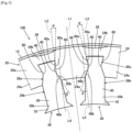
- Figure 3 is an enlarged view showing a connection between the first core 24 and the second core 26.
- the second core 26 has a second yoke forming part 26a and a tooth forming part 26b.
- the second yoke forming part 26a forms the yoke 20a and is sandwiched between a pair of first yoke forming parts 24a adjacent to each other in the circumferential direction.
- the tooth forming part 26b forms the tooth 20b and projects inward in the radial direction from the pair of adjacent first yoke forming parts 24a.
- the tooth forming part 26b has a coil supporting part 30 that is continuous to the second yoke forming part 26a and supports the coil 22 and a flange part 32 provided at a front end (an inner end in the radial direction) of the coil supporting part 30 to project from the coil supporting part 30 to both sides in the circumferential direction.
- the width of the second yoke forming part 26a is set to be equal to or smaller than the width of the coil supporting part 30.
- the minimum width of the second yoke forming part 26a is smaller than the minimum width of the coil supporting part 30.
- the first yoke forming part 24a has a first connection surface 40 to be connected to the second yoke forming part 26a on each side in the circumferential direction.
- the second yoke forming part 26a has a second connection surface 60 to be connected to the first connection surface 40 on each side in the circumferential direction.
- the first connection surface 40 is formed to project outward in the circumferential direction.
- the second connection surface 60 is formed to be recessed inward in the circumferential direction.
- a virtual straight line extending in the radial direction by passing through the center of a first yoke forming part 24a in the circumferential direction is defined as a reference line L1 of the first yoke forming part 24a.
- Figure 3 shows not only the reference line L1 but also straight lines L2 to L5 that are parallel to the reference line L1 when viewed in the axial direction.
- the first connection surface 40 of the first yoke forming part 24a includes a first inclined surface 40a and a second inclined surface 40b.
- the first inclined surface 40a is inclined with respect to the reference line L1 so as to come closer to the reference line L1 in the circumferential direction as it goes outward in the radial direction.
- the second inclined surface 40b is provided on the inner side of the first inclined surface 40a in the radial direction.
- the second inclined surface 40b is inclined with respect to the reference line L1 so as to come closer to the reference line L1 in the circumferential direction as it goes inward in the radial direction.
- the second connection surface 60 of the second yoke forming part 26a When viewed in the axial direction, the second connection surface 60 of the second yoke forming part 26a includes a third inclined surface 60a to be connected to the first inclined surface 40a of the first connection surface 40 and a fourth inclined surface 60b to be connected to the second inclined surface 40b of the first connection surface 40.
- the third inclined surface 60a is inclined with respect to the reference line L1 so as to extend along the first inclined surface 40a to which the third inclined surface 60a is to be connected
- the fourth inclined surface 60b is inclined with respect to the reference line L1 so as to extend along the second inclined surface 40b to which the fourth inclined surface 60b is to be connected.
- an angle ⁇ formed by the reference line L1 (straight lines L2 and L3) and the first inclined surface 40a is set to be 5° or more, for example.
- a compression stress occurs in the first yoke forming part 24a.
- the compression stress is supposed to occur in a direction perpendicular to the first inclined surface 40a.
- the core loss of the first yoke forming part 24a increases when the first yoke forming part 24a is excited in a direction parallel to the direction of application of the compression stress.
- the first yoke forming part 24a is mainly excited in the circumferential direction. Therefore, if the compression stress occurring in the circumferential direction in the first yoke forming part 24a can be reduced, the increase of the core loss can be reduced.
- the angle ⁇ is preferably set to 5° or more in order to adequately reduce application of the compression stress in the circumferential direction from the third inclined surface 60a to the first yoke forming part 24a.
- the angle formed by the reference line L1 and the third inclined surface 60a is set in the same way as the angle ⁇ .
- the first yoke forming part 24a is appropriately prevented from moving outward in the radial direction with respect to the second yoke forming part 26a, and the second yoke forming part 26a is appropriately prevented from moving inward in the radial direction with respect to the first yoke forming part 24a. In this way, an adequate fixture strength of the first core 24 and the second core 26 can be ensured.
- the angle ⁇ is set to 30° or less, for example.
- the direction of the magnetic flux flowing in the second core 26 varies as the rotor 12 (see Figure 1 ) rotates.
- the magnetic flux may mainly flow in the circumferential direction or may flow in the radial direction in the tooth forming part 26b and then change the direction to the circumferential direction in a smooth curve in the second yoke forming part 26a to flow into the first yoke forming part 24a.
- An air gap usually occurs between the first inclined surface 40a and the third inclined surface 60a due to a problem with working precision.
- the first inclined surface 40a and the third inclined surface 60a are inclined with respect to the reference line L1, so that the air gap is also formed to extend in an inclined direction with respect to the reference line L1.
- the flow direction of the magnetic flux and the length direction of the air gap become more parallel to each other when the magnetic flux flows from the tooth forming part 26b into the first yoke forming part 24a in a curve as described above.
- the length of the air gap in the flow direction of the magnetic flux increases, and excitation of the yoke 20a is inhibited. As a result, the core loss increases.
- the angle ⁇ is preferably set to 30° or less so that the length of the air gap in the flow direction of the magnetic flux decreases.
- the angle ⁇ is preferably set to 30° or less so that the length of the air gap in the flow direction of the magnetic flux decreases.
- an angle ⁇ formed by the reference line L1 (straight lines L4 and L5) and the second inclined surface 40b is set to fall within a range from 180°/n+5° to 180°/n+30°, provided that n denotes the number of teeth 20b of the stator core 20 designed.
- the angle formed by the reference line L1 and the fourth inclined surface 60b of the second yoke forming part 26a is set in the same way as the angle ⁇ .
- the increase of the core loss can be reduced by reducing the compression stress in the circumferential direction.
- the angle ⁇ is appropriately prevented from moving inward in the radial direction with respect to the second yoke forming part 26a, and the second yoke forming part 26a is appropriately prevented from moving outward in the radial direction with respect to the first yoke forming part 24a. In this way, an adequate fixture strength of the first core 24 and the second core 26 can be ensured.
- each connection part 24b is configured to be easily deformed when the first core 24 is bent into an annular or arc shape.
- the thickness of the connection part 24b in the radial direction is set to be adequately smaller than the length of the second yoke forming part 26a in the radial direction.
- the thickness of a portion of the connection part 24b that has the smallest thickness in the radial direction is set to be equal to or less than a half of the length of the second yoke forming part 26a in the radial direction.
- the thickness of a portion of the connection part 24b that has the smallest thickness in the radial direction is preferably set to be equal to or less than a fifth of the length of the second yoke forming part 26a in the radial direction and is more preferably set to be equal to or less than a tenth of the length of the second yoke forming part 26a in the radial direction.
- the length of the recess 28 in the circumferential direction is set to be larger than the thickness of a portion of the second yoke forming part 26a that has the smallest thickness in the circumferential direction. Furthermore, in this embodiment, the length of the recess 28 in the circumferential direction is set to be larger than the thickness of a portion of the second yoke forming part 26a that has the largest thickness in the circumferential direction.
- Figure 4 is a diagram for illustrating the manufacturing method for the stator 10.
- the first core 24 in the expanded state is first arranged on the outer side of the coil 22 arranged in an annular shape when viewed in the axial direction.
- the second core 26 is then inserted into the coil 22 and the first core 24 (more specifically, between a pair of first yoke forming parts 24a) from the inner side of the coil 22 while bending the first core 24 along the outer circumference of the coil 22.
- the plurality of second cores 26 are sequentially inserted into the coil 22 and the first core 24.
- the stator 10 (see Figure 1 ) is manufactured by attaching the coil 22 and the plurality of second cores 26 to the first core 24 in this way.
- wave winding is a way of winding that can reduce the overlapping of windings compared with lap winding. Wave winding allows a conductor to be arranged without wasting space, so that the size of the coil ends can be reduced.
- working space between the teeth is small, and therefore the teeth interfere with the conductor working robot when the conductor is shaped for wave winding in order to directly wind the conductor around the stator core. Therefore, it is practically difficult to adopt wave winding to directly wind the conductor around the stator core.
- the width of the second yoke forming part 26a is smaller than the width of the coil supporting part 30. Since the second yoke forming part 26a has a smaller width in this way, the second yoke forming part 26a can be easily inserted between a pair of adjacent first yoke forming parts 24a.
- the first core 24 and the second core 26 are connected to each other with the first inclined surface 40a and the third inclined surface 60a in contact with each other and the second inclined surface 40b and the fourth inclined surface 60b in contact with each other on the inner side of the first inclined surface 40a and the third inclined surface 60a in the radial direction.
- the first connection surface 40 is inclined with respect to the reference line L1 so as to come closer to the reference line L1 in the circumferential direction as it goes outward in the radial direction
- the second inclined surface 40b is inclined with respect to the reference line L1 so as to come closer to the reference line L1 in the circumferential direction as it goes inward in the radial direction.
- the third inclined surface 60a is inclined with respect to the reference line L1 so as to extend along the first inclined surface 40a to which the third inclined surface 60a is to be connected
- the fourth inclined surface 60b is inclined with respect to the reference line L1 so as to extend along the second inclined surface 40b to which the fourth inclined surface 60b is to be connected.
- the first core 24 is prevented from moving outward in the radial direction by the first inclined surface 40a of the first core 24 coming into contact with the third inclined surface 60a of the second core 26.
- the second core 26 is prevented from moving inward in the radial direction by the third inclined surface 60a of the second core 26 coming into contact with the first inclined surface 40a of the first core 24.
- the second core 26 is prevented from moving outward in the radial direction by the fourth inclined surface 60b of the second core 26 coming into contact with the second inclined surface 40b of the first core 24.
- the second yoke forming part 26a of the second core 26 can be fixed between a pair of adjacent first yoke forming parts 24a with reliability. That is, the yoke 20a and the plurality of teeth 20b can be appropriately fixed to each other. As a result, occurrence of vibrations in the stator 10 can be adequately prevented during use of the rotary electric machine 100.
- the first connection surface 40 of the first yoke forming part 24a is shaped to project outward in the circumferential direction
- the second connection surface 60 of the second yoke forming part 26a is shaped to be recessed inward in the circumferential direction.
- the second core 26 can be moved effortlessly into an appropriate position (designed position) along the first connection surface 40, even if the dimensional accuracy of the first connection surface 40 and the second connection surface 60 is not so high. Therefore, the first connection surface 40 and the second connection surface 60 can be in contact with each other under adequate force. As a result, the rigidity and shape precision of the stator core 20 can be adequately high.
- first connection surface 40 and the second connection surface 60 are in contact with each other under adequate force as described above, a compression stress of a certain magnitude occurs in the circumferential direction at the contact between the first yoke forming part 24a and the second yoke forming part 26a. Therefore, for example, when the first core 24 is made of a grain-oriented electromagnetic steel sheet in order that the first yoke forming part 24a has a high magnetic permeability in the circumferential direction, the flow of the magnetic flux may be inhibited at the contact between the first yoke forming part 24a and the second yoke forming part 26a.
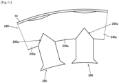
- the stator may be configured as shown in Figure 11 , for example. With the stator shown in Figure 11 , a second yoke forming part 260a of a second core 260 is inserted between a pair of first yoke forming parts 240a of a first core 240 and fixed to the first core 240 by bonding.
- the recess 28 is formed in the outer surface of the connection part 24b located on the outer side of the second core 26 in the radial direction.
- the connection part 24b can be prevented from projecting outward in the radial direction from the first yoke forming part 24a even if the connection part 24b is deformed to bulge outward. Therefore, the stator 10 can be smoothly inserted into the case 14.
- the recess 28 can be used as a point of fixture at which the stator 10 is fixed to the case 14. If shrink fit is not used for fixing the case 14 to the stator 10, the core loss degradation (core loss increase) of the stator core 20 because of the compression stress can be avoided.
- connection part 24b is formed integrally with a pair of adjacent first yoke forming parts 24a.
- an adequate binding force can be ensured between the pair of first yoke forming parts 24a and the connection part 24b, so that the rigidity and shape precision of the stator core 20 can be adequately high.
- the first connection surface 40 and the second connection surface 60 at which the first core 24 and the second core 26 are connected to each other are inclined with respect to the radial direction. Therefore, a compression stress occurs in a direction inclined with respect to the radial direction at the connection between the first core 24 and the second core 26. In other words, a compression stress in the radial direction can be prevented from being applied from the second core 26 to the first core 24. Furthermore, with the rotary electric machine 100 according to this embodiment, the first yoke forming parts 24a and the case 14 come into contact with each other when the stator 10 is inserted into the case 14.
- the compression stress in the circumferential direction mainly occurs in the connection parts 24b, the compression stress applied from the case 14 to the second core 26 can be reduced.
- the first inclined surface 40a and the second inclined surface 40b are inclined with respect to the reference line L1, the direction of the compression stress applied from the first core 24 to the second core 26 is limited. As a result, the occurrence of the compression stress in the radial direction in the second core 26 is reduced.
- the teeth 20b are mainly excited in the radial direction, and a portion of the yoke 20a that is close to the teeth 20b also tends to be excited in a direction close to the radial direction. Therefore, the teeth 20b and the yoke 20a can be efficiently excited due to the compression stress acting in the radial direction in the second core 26 being reduced as described above.
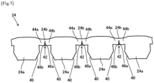
- Figure 5 is a diagram showing a variation of the first core 24.
- the first core 24 shown in Figure 5 differs from the first core 24 shown in Figure 2 in the points described below.
- a notch 42 is formed in the connection part 24b on an inner side thereof in the radial direction, thereby partitioning the connection part 24b into a first connection part 44a and a second connection part 44b.
- the first connection part 44a and the second connection part 44b are arranged side by side in the circumferential direction of the stator core 20.
- portions located on straight lines extending in the radial direction by passing through the centers of the teeth 20b in the circumferential direction are excited to a lesser extent.
- most of the deformation of the first core 24 intensively occurs in the portions that are excited to a lesser extent, so that the amount of core loss degradation of the first core 24 due to the deformation is extremely low.
- Figure 8 is a diagram showing another example of the shape of the first inclined surface 40a, the second inclined surface 40b, the third inclined surface 60a, and the fourth inclined surface 60b.
- Figure 8 not only the reference line L1 but also straight lines L6 and L7 that are parallel to the reference line L1 when viewed in the axial direction are shown.
- the first inclined surface 40a, the second inclined surface 40b, the third inclined surface 60a, and the fourth inclined surface 60b may be formed in an arch shape.
- first connection surface 40 and the second connection surface 60 each have two inclined surfaces that are inclined with respect to the reference line L1.
- first connection surface and the second connection surface may each include a surface that is parallel to the reference line L1 when viewed in the axial direction.
- first core 24 is bent into an annular shape and used as a component of the stator core 20.
- a plurality of first cores 24 bent in an arc shape may be connected to each other into an annular shape and used as a component of the stator core 20.
- a part of the stator core may be formed by a band-like first core 24 and a plurality of second cores 26, and another part of the stator core may be formed by a core other than the band-like core (expanded core).
- the yoke and the teeth may be integrally formed.
- a plurality of separate yoke forming parts may be provided (that is, in the first core 24 described above, the connection parts 24b are omitted, and only two or more first yoke forming parts 24a are provided), and second cores 26 may be sandwiched between the yoke forming parts.
- the length of the recess 28 in the circumferential direction is set to be larger than the thickness of the portion of the second yoke forming part 26a that has the smallest thickness in the circumferential direction.
- the length of the recess 28 in the circumferential direction may be set to be smaller than the thickness of the portion of the second yoke forming part 26a that has the smallest thickness in the circumferential direction.
- the length of the recess 28 in the circumferential direction may be set to be smaller than the thickness of the portion of the second yoke forming part 26a that has the largest thickness in the circumferential direction and is larger than the thickness of the portion of the second yoke forming part 26a that has the smallest thickness in the circumferential direction.
- the recesses 28 adjacent to each other in the circumferential direction are separate from each other.
- the recesses 28 adjacent to each other in the circumferential direction may be continuous to each other.
- a split-type stator core having a yoke and teeth that can be appropriately fixed and a rotary electric machine provided with the stator core can be provided.
Landscapes
- Engineering & Computer Science (AREA)
- Power Engineering (AREA)
- Manufacturing & Machinery (AREA)
- Iron Core Of Rotating Electric Machines (AREA)
- Manufacture Of Motors, Generators (AREA)
Abstract
Description
- The present invention relates to a split-type stator core, a manufacturing method for a stator including the stator core, and a rotary electric machine provided with the stator core.
- A split-type stator core in a structure in which a yoke and teeth are separated from each other is often used as a stator core for a rotary electric machine, such as an electric motor and a generator.
- For example, Patent Document 1 discloses a stator for a rotary electric machine that includes a stator core formed by a combination of a plurality of yoke core parts located on the outer peripheral side of slots and tooth core parts that connect the plurality of yoke core parts to each other. The yoke core part has a circumferential contact surface, which is opposed to the tooth core part, on each side thereof in a circumferential direction of the stator core. Similarly, the tooth core part has a circumferential contact surface, which is opposed to the yoke core part, on each side thereof in the circumferential direction. Each circumferential contact surface is shaped to allow the yoke core part to be disposed between a pair of adjacent tooth core parts from the outer peripheral side. Furthermore, each circumferential contact surface is shaped to prevent the tooth core part from being drawn from between the pair of adjacent yoke core parts to the inner peripheral side.
- With the stator for a rotary electric machine disclosed in Patent Document 1, the stator core can be completed by disposing a plurality of tooth core parts on a previously wound coil and then combining a plurality of yoke core parts and the plurality of tooth core parts. In this way, the coil can be easily disposed on the stator core.
- Patent Document 1:
JP2010-233387A - As described above, with the stator for a rotary electric machine in Patent Document 1, each circumferential contact surface of the yoke core parts and the tooth core parts is shaped to prevent the tooth core part from being drawn from between the pair of yoke core parts to the inner peripheral side. Therefore, when the yoke core parts are fixed at appropriate positions, the tooth core parts can be prevented from moving to the inner peripheral side with respect to the yoke core parts.
- However, the circumferential contact surfaces cannot adequately prevent the yoke core parts from moving to the outer peripheral side with respect to the tooth core parts. Therefore, the stator for a rotary electric machine in Patent Document 1 requires means for preventing the yoke core parts from moving to the outer peripheral side in addition to the circumferential contact surfaces. However, even if such means is provided, it is difficult to adequately prevent movement of the yoke core parts.
- In view of this, an objective of the present invention is to provide a split-type stator core having a yoke and teeth that can be appropriately fixed and a rotary electric machine provided with the stator core.
- The gist of the present invention includes a stator core, a manufacturing method for a stator, and a rotary electric machine described below.
- (1) A split-type stator core having a cylindrical yoke and a plurality of teeth that project from the yoke inward in a radial direction of the yoke, including:
- a band-like first core; and a plurality of second cores that are fixed to the first core so as to project from the first core inward in the radial direction of the yoke,
- wherein the first core has a plurality of first yoke forming parts that form the yoke and are arranged at intervals in a circumferential direction of the yoke, and a plurality of connection parts that connect outer edges in the radial direction of the first yoke forming parts adjacent to each other in the circumferential direction to each other,
- each of the second cores has a second yoke forming part that forms the yoke and is sandwiched between a pair of the first yoke forming parts adjacent in the circumferential direction, and a tooth forming part that projects inward in the radial direction from the pair of first yoke forming parts to form one of the teeth,
- the first yoke forming part has a first connection surface to be connected to the second yoke forming part on each side in the circumferential direction,
- the second yoke forming part has a second connection surface to be connected to the first connection surface of the first yoke forming part on each side in the circumferential direction,
- when viewed in an axial direction of the yoke, provided that a virtual straight line extending in the radial direction by passing through a center of the first yoke forming part in the circumferential direction is a reference line of the first yoke forming part, the first connection surface includes a first inclined surface that is inclined with respect to the reference line so as to come closer to the reference line in the circumferential direction as it goes outward in the radial direction, and a second inclined surface that is provided on an inner side of the first inclined surface in the radial direction and is inclined with respect to the reference line so as to come closer to the reference line in the circumferential direction as it goes inward in the radial direction, and
- when viewed in the axial direction, the second connection surface to be connected to the first connection surface of the first yoke forming part has a third inclined surface and a fourth inclined surface that are inclined with respect to the reference line so as to extend along the first inclined surface and the second inclined surface of the first yoke forming part, respectively.
- (2) The stator core according to (1) described above, wherein the tooth forming part has a coil supporting part that supports a coil, and
in the circumferential direction, a width of the second yoke forming part is smaller than a width of the coil supporting part. - (3) The stator core according to (1) or (2) described above, wherein when viewed in the axial direction, provided that a virtual circle that is centered on an axial center of the yoke and circumscribes the plurality of first yoke forming parts is a reference circle, a recess that is recessed inward from the reference circle in the radial direction is formed in an outer surface of the connection part in the radial direction.
- (4) The stator core according to any one of (1) to (3) described above, wherein the connection part is formed integrally with the pair of first yoke forming parts adjacent to each other.
- (5) The stator core according to any one of (1) to (4) described above, wherein the connection part has a first connection part and a second connection part arranged side by side in the circumferential direction,
- the first connection part has a third connection surface that faces to the second connection part in the circumferential direction,
- the second connection part has a fourth connection surface that faces to the first connection part in the circumferential direction and is to be connected to the third connection surface, and
- the first connection part and the second connection part are integrally continuous to each other on an outer side of the third connection surface and the fourth connection surface in the radial direction.
- (6) The stator core according to any one of (1) to (5) described above, wherein the first core and the plurality of second cores each include a plurality of non-oriented electromagnetic steel sheets stacked on one another.
- (7) A method of manufacturing a stator including a stator core according to any one of (1) to (6) described above, wherein
- the first core in an expanded state is disposed on an outer side of a coil arranged in an annular shape, and
- the coil and the plurality of second cores are attached to the first core by sequentially inserting the plurality of second cores into the coil and the first core from an inner side of the coil while bending the first core along an outer circumference of the coil.
- (8) A rotary electric machine, including:
- a stator core according to any one of (1) to (6) described above;
- a coil supported by the plurality of teeth of the stator core; and
- a rotor disposed inside the stator core.
- According to the present invention, a split-type stator core having a yoke and teeth that can be appropriately fixed and a rotary electric machine provided with the stator core can be provided.
-
- [
Figure 1] Figure 1 is a diagram showing a configuration of a rotary electric machine according to an embodiment of the present invention. - [
Figure 2] Figure 2 is a diagram showing a first core. - [
Figure 3] Figure 3 is an enlarged view showing a connection between the first core and a second core. - [
Figure 4] Figure 4 is a diagram for illustrating a manufacturing method for a stator. - [
Figure 5] Figure 5 is a diagram showing another example of the first core. - [
Figure 6] Figure 6 is a diagram showing another example of the first core. - [
Figure 7] Figure 7 is a diagram showing another example of the first core. - [
Figure 8] Figure 8 is a diagram showing another example of the rotary electric machine. - [
Figure 9] Figure 9 is a diagram showing another example of the rotary electric machine. - [
Figure 10] Figure 10 is a diagram showing another example of the rotary electric machine. - [
Figure 11] Figure 11 is a diagram showing an example of the stator for reference. - In the following, a stator core according to an embodiment of the present invention and a rotary electric machine provided with the same will be described with reference to the drawings.
-
Figure 1 is a schematic diagram showing a rotary electric machine according to an embodiment of the present invention.Figure 1 shows a rotaryelectric machine 100 viewed in an axial direction of ayoke 20a described later.Figure 1 shows only a quarter of a circumferential region of the rotaryelectric machine 100. - As shown in
Figure 1 , the rotaryelectric machine 100 includes astator 10, arotor 12, and acase 14. For the sake of clarity, therotor 12 and acoil 22 described later are simplified in the drawing. - The
stator 10 has astator core 20 and thecoil 22. Therotor 12 is disposed inside thestator core 20 with an axial center (center of rotation) thereof coincident with an axial center of thestator core 20. Thecase 14 is attached to an outer peripheral surface of thestator core 20 by shrink fit, for example. Therotor 12 and thecase 14 can have various known configurations, and therefore, detailed descriptions thereof will be omitted. - The
stator core 20 has thecylindrical yoke 20a and a plurality ofteeth 20b projecting inward in the radial direction of theyoke 20a from theyoke 20a. Thecoil 22 is supported on the plurality ofteeth 20b. In this embodiment, thecoil 22 may be supported on the plurality ofteeth 20b in the distributed winding manner or in the concentrated winding manner. - In this embodiment, the
stator core 20 includes twenty-fourteeth 20b. However, the number of teeth is not limited to 24. In the following description, a direction simply referred to as an axial direction means the axial direction of theyoke 20a, a direction simply referred to as a circumferential direction means the circumferential direction of theyoke 20a, and a direction simply referred to as a radial direction means the radial direction of theyoke 20a. - In this embodiment, the
stator core 20 is a split-type stator core and includes a band-likefirst core 24 and a plurality ofsecond cores 26 fixed to thefirst core 24 and projecting inward in the radial direction from thefirst core 24. Thefirst core 24 and thesecond cores 26 can each be formed of a plurality of sheet materials of a predetermined shape formed by punching an electromagnetic steel sheet, for example. - In this embodiment, the electromagnetic steel sheet used to form the
first core 24 and thesecond cores 26 is a known non-oriented electromagnetic steel sheet. Whether the steel sheet forming thefirst core 24 and thesecond cores 26 is a grain-oriented electromagnetic steel sheet or a non-oriented electromagnetic steel sheet can be discriminated by measuring the magnetic flux density of the steel sheet. The magnetic flux density can be measured with a well-known gauss meter. -
Figure 2 is a diagram showing thefirst core 24,Figure 2(a) shows thefirst core 24 assembled in the rotaryelectric machine 100, andFigure 2(b) shows thefirst core 24 expanded yet to be assembled in the rotaryelectric machine 100. - As described in detail later, one or more band-like
first cores 24 used in the rotaryelectric machine 100 are bent into an annular or arc shape. In this embodiment, onefirst core 24 bent into an annular shape is used. As shown inFigures 1 and2 , thefirst core 24 has a plurality of firstyoke forming parts 24a and a plurality ofconnection parts 24b. The plurality of firstyoke forming parts 24a form theyoke 20a and are arranged at intervals in the circumferential direction. Eachconnection part 24b connects firstyoke forming parts 24a that are adjacent to each other in the circumferential direction at outer peripheral edges thereof in the radial direction. In this embodiment, eachconnection part 24b is formed integrally with a pair of adjacent firstyoke forming parts 24a. - As shown in
Figure 2(a) , when viewed in the axial direction, a virtual circle that is centered on the axial center of theyoke 20a and circumscribes the plurality of firstyoke forming parts 24a is defined as areference circle 50. In this embodiment, when viewed in the axial direction, arecess 28 that is recessed inward from thereference circle 50 in the radial direction is formed in an outer surface of theconnection part 24b in the radial direction. In this embodiment, thefirst core 24 is configured such that the whole of the outer surfaces of theconnection parts 24b is recessed. -
Figure 3 is an enlarged view showing a connection between thefirst core 24 and thesecond core 26. As shown inFigures 1 and3 , in this embodiment, thesecond core 26 has a secondyoke forming part 26a and atooth forming part 26b. - The second
yoke forming part 26a forms theyoke 20a and is sandwiched between a pair of firstyoke forming parts 24a adjacent to each other in the circumferential direction. Thetooth forming part 26b forms thetooth 20b and projects inward in the radial direction from the pair of adjacent firstyoke forming parts 24a. In this embodiment, thetooth forming part 26b has acoil supporting part 30 that is continuous to the secondyoke forming part 26a and supports thecoil 22 and aflange part 32 provided at a front end (an inner end in the radial direction) of thecoil supporting part 30 to project from thecoil supporting part 30 to both sides in the circumferential direction. In this embodiment, in the circumferential direction, the width of the secondyoke forming part 26a is set to be equal to or smaller than the width of thecoil supporting part 30. In the example shown inFigure 1 , in the circumferential direction, the minimum width of the secondyoke forming part 26a is smaller than the minimum width of thecoil supporting part 30. - As shown in
Figure 3 , the firstyoke forming part 24a has afirst connection surface 40 to be connected to the secondyoke forming part 26a on each side in the circumferential direction. The secondyoke forming part 26a has asecond connection surface 60 to be connected to thefirst connection surface 40 on each side in the circumferential direction. Thefirst connection surface 40 is formed to project outward in the circumferential direction. Thesecond connection surface 60 is formed to be recessed inward in the circumferential direction. - As shown in
Figures 1 and3 , when viewed in the axial direction, a virtual straight line extending in the radial direction by passing through the center of a firstyoke forming part 24a in the circumferential direction is defined as a reference line L1 of the firstyoke forming part 24a.Figure 3 shows not only the reference line L1 but also straight lines L2 to L5 that are parallel to the reference line L1 when viewed in the axial direction. - As shown in
Figure 3 , thefirst connection surface 40 of the firstyoke forming part 24a includes a firstinclined surface 40a and a secondinclined surface 40b. When viewed in the axial direction, the firstinclined surface 40a is inclined with respect to the reference line L1 so as to come closer to the reference line L1 in the circumferential direction as it goes outward in the radial direction. The secondinclined surface 40b is provided on the inner side of the firstinclined surface 40a in the radial direction. The secondinclined surface 40b is inclined with respect to the reference line L1 so as to come closer to the reference line L1 in the circumferential direction as it goes inward in the radial direction. - When viewed in the axial direction, the
second connection surface 60 of the secondyoke forming part 26a includes a thirdinclined surface 60a to be connected to the firstinclined surface 40a of thefirst connection surface 40 and a fourthinclined surface 60b to be connected to the secondinclined surface 40b of thefirst connection surface 40. The thirdinclined surface 60a is inclined with respect to the reference line L1 so as to extend along the firstinclined surface 40a to which the thirdinclined surface 60a is to be connected, and the fourthinclined surface 60b is inclined with respect to the reference line L1 so as to extend along the secondinclined surface 40b to which the fourthinclined surface 60b is to be connected. - In this embodiment, when viewed in the axial direction, an angle α formed by the reference line L1 (straight lines L2 and L3) and the first
inclined surface 40a is set to be 5° or more, for example. In this embodiment, when the firstinclined surface 40a and the thirdinclined surface 60a come into contact with each other, a compression stress occurs in the firstyoke forming part 24a. The compression stress is supposed to occur in a direction perpendicular to the firstinclined surface 40a. On the other hand, the core loss of the firstyoke forming part 24a increases when the firstyoke forming part 24a is excited in a direction parallel to the direction of application of the compression stress. In this embodiment, the firstyoke forming part 24a is mainly excited in the circumferential direction. Therefore, if the compression stress occurring in the circumferential direction in the firstyoke forming part 24a can be reduced, the increase of the core loss can be reduced. In view of this, in this embodiment, the angle α is preferably set to 5° or more in order to adequately reduce application of the compression stress in the circumferential direction from the thirdinclined surface 60a to the firstyoke forming part 24a. When viewed in the axial direction, the angle formed by the reference line L1 and the thirdinclined surface 60a is set in the same way as the angle α. In this embodiment, by setting the angle α to 5° or more, the firstyoke forming part 24a is appropriately prevented from moving outward in the radial direction with respect to the secondyoke forming part 26a, and the secondyoke forming part 26a is appropriately prevented from moving inward in the radial direction with respect to the firstyoke forming part 24a. In this way, an adequate fixture strength of thefirst core 24 and thesecond core 26 can be ensured. - In addition, in this embodiment, the angle α is set to 30° or less, for example. With the rotary
electric machine 100 according to this embodiment, the direction of the magnetic flux flowing in thesecond core 26 varies as the rotor 12 (seeFigure 1 ) rotates. Specifically, the magnetic flux may mainly flow in the circumferential direction or may flow in the radial direction in thetooth forming part 26b and then change the direction to the circumferential direction in a smooth curve in the secondyoke forming part 26a to flow into the firstyoke forming part 24a. An air gap usually occurs between the firstinclined surface 40a and the thirdinclined surface 60a due to a problem with working precision. When viewed in the axial direction, the firstinclined surface 40a and the thirdinclined surface 60a are inclined with respect to the reference line L1, so that the air gap is also formed to extend in an inclined direction with respect to the reference line L1. As the inclination angle of theinclined surfaces tooth forming part 26b into the firstyoke forming part 24a in a curve as described above. In this case, the length of the air gap in the flow direction of the magnetic flux increases, and excitation of theyoke 20a is inhibited. As a result, the core loss increases. In view of this, in this embodiment, the angle α is preferably set to 30° or less so that the length of the air gap in the flow direction of the magnetic flux decreases. In addition, by setting the angle α to 30° or less, interference between thefirst core 24 and thesecond core 26 can be appropriately prevented when inserting thesecond core 26 into thefirst core 24. This facilitates insertion of thesecond core 26 into thefirst core 24. - In addition, when viewed in the axial direction, an angle β formed by the reference line L1 (straight lines L4 and L5) and the second
inclined surface 40b is set to fall within a range from 180°/n+5° to 180°/n+30°, provided that n denotes the number ofteeth 20b of thestator core 20 designed. When viewed in the axial direction, the angle formed by the reference line L1 and the fourthinclined surface 60b of the secondyoke forming part 26a is set in the same way as the angle β. By setting the angle β to 180°/n+5° or more, application of the compression stress in the circumferential direction from the fourthinclined surface 60b to the firstyoke forming part 24a can be reduced. Since the firstyoke forming part 24a is mainly excited in the circumferential direction as described above, the increase of the core loss can be reduced by reducing the compression stress in the circumferential direction. In addition, by setting the angle β to 180°/n+5° or more, the firstyoke forming part 24a is appropriately prevented from moving inward in the radial direction with respect to the secondyoke forming part 26a, and the secondyoke forming part 26a is appropriately prevented from moving outward in the radial direction with respect to the firstyoke forming part 24a. In this way, an adequate fixture strength of thefirst core 24 and thesecond core 26 can be ensured. - In this embodiment, each
connection part 24b is configured to be easily deformed when thefirst core 24 is bent into an annular or arc shape. Specifically, the thickness of theconnection part 24b in the radial direction is set to be adequately smaller than the length of the secondyoke forming part 26a in the radial direction. In this embodiment, the thickness of a portion of theconnection part 24b that has the smallest thickness in the radial direction is set to be equal to or less than a half of the length of the secondyoke forming part 26a in the radial direction. The thickness of a portion of theconnection part 24b that has the smallest thickness in the radial direction is preferably set to be equal to or less than a fifth of the length of the secondyoke forming part 26a in the radial direction and is more preferably set to be equal to or less than a tenth of the length of the secondyoke forming part 26a in the radial direction. - Furthermore, in this embodiment, the length of the
recess 28 in the circumferential direction is set to be larger than the thickness of a portion of the secondyoke forming part 26a that has the smallest thickness in the circumferential direction. Furthermore, in this embodiment, the length of therecess 28 in the circumferential direction is set to be larger than the thickness of a portion of the secondyoke forming part 26a that has the largest thickness in the circumferential direction. - In the following, an example of a manufacturing method for the
stator 10 will be briefly described.Figure 4 is a diagram for illustrating the manufacturing method for thestator 10. - As shown in
Figure 4(a) , in the manufacturing method according to this embodiment, thefirst core 24 in the expanded state is first arranged on the outer side of thecoil 22 arranged in an annular shape when viewed in the axial direction. As shown inFigures 4(b) and 4(c) , thesecond core 26 is then inserted into thecoil 22 and the first core 24 (more specifically, between a pair of firstyoke forming parts 24a) from the inner side of thecoil 22 while bending thefirst core 24 along the outer circumference of thecoil 22. In the same manner, the plurality ofsecond cores 26 are sequentially inserted into thecoil 22 and thefirst core 24. The stator 10 (seeFigure 1 ) is manufactured by attaching thecoil 22 and the plurality ofsecond cores 26 to thefirst core 24 in this way. - In the case of directly winding a wire around the stator core, lap winding, which involves overlapping of windings, is typically used. However, the size of the coil ends is inevitably large due to the interference between the windings. Wave winding is a way of winding that can reduce the overlapping of windings compared with lap winding. Wave winding allows a conductor to be arranged without wasting space, so that the size of the coil ends can be reduced. However, working space between the teeth is small, and therefore the teeth interfere with the conductor working robot when the conductor is shaped for wave winding in order to directly wind the conductor around the stator core. Therefore, it is practically difficult to adopt wave winding to directly wind the conductor around the stator core. On the other hand, in the case of assembling a segment coil formed by a plurality of conductors shaped for wave winding in advance onto the stator core, wave winding is possible. However, a plurality of conductors need to be connected by welding at the coil ends. Therefore, in the case where the segment coil is used, the size of the coil ends is also inevitably large at the welded parts. To the contrary, in the manufacturing method according to this embodiment, a coil shaped for wave winding at both coil ends is prepared in advance under less restrictions of working space, and therefore, the
stator 10 can be manufactured without using a segment coil. In this case, the size of the coil ends can be easily reduced. - In this embodiment, in the circumferential direction, the width of the second
yoke forming part 26a is smaller than the width of thecoil supporting part 30. Since the secondyoke forming part 26a has a smaller width in this way, the secondyoke forming part 26a can be easily inserted between a pair of adjacent firstyoke forming parts 24a. - In this embodiment, as described with reference to
Figure 3 , thefirst core 24 and thesecond core 26 are connected to each other with the firstinclined surface 40a and the thirdinclined surface 60a in contact with each other and the secondinclined surface 40b and the fourthinclined surface 60b in contact with each other on the inner side of the firstinclined surface 40a and the thirdinclined surface 60a in the radial direction. Thefirst connection surface 40 is inclined with respect to the reference line L1 so as to come closer to the reference line L1 in the circumferential direction as it goes outward in the radial direction, and the secondinclined surface 40b is inclined with respect to the reference line L1 so as to come closer to the reference line L1 in the circumferential direction as it goes inward in the radial direction. The thirdinclined surface 60a is inclined with respect to the reference line L1 so as to extend along the firstinclined surface 40a to which the thirdinclined surface 60a is to be connected, and the fourthinclined surface 60b is inclined with respect to the reference line L1 so as to extend along the secondinclined surface 40b to which the fourthinclined surface 60b is to be connected. - With the configuration described above, the
first core 24 is prevented from moving outward in the radial direction by the firstinclined surface 40a of thefirst core 24 coming into contact with the thirdinclined surface 60a of thesecond core 26. Thesecond core 26 is prevented from moving inward in the radial direction by the thirdinclined surface 60a of thesecond core 26 coming into contact with the firstinclined surface 40a of thefirst core 24. Furthermore, thesecond core 26 is prevented from moving outward in the radial direction by the fourthinclined surface 60b of thesecond core 26 coming into contact with the secondinclined surface 40b of thefirst core 24. In this way, in this embodiment, the secondyoke forming part 26a of thesecond core 26 can be fixed between a pair of adjacent firstyoke forming parts 24a with reliability. That is, theyoke 20a and the plurality ofteeth 20b can be appropriately fixed to each other. As a result, occurrence of vibrations in thestator 10 can be adequately prevented during use of the rotaryelectric machine 100. - In this embodiment, the
first connection surface 40 of the firstyoke forming part 24a is shaped to project outward in the circumferential direction, and thesecond connection surface 60 of the secondyoke forming part 26a is shaped to be recessed inward in the circumferential direction. In this case, thesecond core 26 can be moved effortlessly into an appropriate position (designed position) along thefirst connection surface 40, even if the dimensional accuracy of thefirst connection surface 40 and thesecond connection surface 60 is not so high. Therefore, thefirst connection surface 40 and thesecond connection surface 60 can be in contact with each other under adequate force. As a result, the rigidity and shape precision of thestator core 20 can be adequately high. - In this embodiment, since the
first connection surface 40 and thesecond connection surface 60 are in contact with each other under adequate force as described above, a compression stress of a certain magnitude occurs in the circumferential direction at the contact between the firstyoke forming part 24a and the secondyoke forming part 26a. Therefore, for example, when thefirst core 24 is made of a grain-oriented electromagnetic steel sheet in order that the firstyoke forming part 24a has a high magnetic permeability in the circumferential direction, the flow of the magnetic flux may be inhibited at the contact between the firstyoke forming part 24a and the secondyoke forming part 26a. In that case, the increase of the core loss may be unable to be adequately reduced even if thefirst core 24 is made of a grain-oriented electromagnetic steel sheet. Therefore, in the case of making the first core of a grain-oriented electromagnetic steel sheet, the stator may be configured as shown inFigure 11 , for example. With the stator shown inFigure 11 , a secondyoke forming part 260a of asecond core 260 is inserted between a pair of firstyoke forming parts 240a of afirst core 240 and fixed to thefirst core 240 by bonding. In this case, compared with thestator 10 according to this embodiment in which thefirst core 24 and thesecond core 26 are fixed to each other by the firstyoke forming parts 24a being sandwiched between the adjacent secondyoke forming parts 26a, the occurrence of a compression stress in the circumferential direction in the firstyoke forming parts 240a can be reduced. Therefore, the increase of the core loss can be reduced. However, with thestator 10 according to this embodiment, thefirst core 24 is made of a non-oriented electromagnetic steel sheet. Therefore, the flow of the magnetic flux is not inhibited even if a compression stress of a certain magnitude occurs in the circumferential direction at the contact between the firstyoke forming part 24a and the secondyoke forming part 26a. Therefore, the increase of the core loss can be reduced. - In this embodiment, furthermore, the
recess 28 is formed in the outer surface of theconnection part 24b located on the outer side of thesecond core 26 in the radial direction. Thus, when attaching thesecond core 26 to thefirst core 24, theconnection part 24b can be prevented from projecting outward in the radial direction from the firstyoke forming part 24a even if theconnection part 24b is deformed to bulge outward. Therefore, thestator 10 can be smoothly inserted into thecase 14. Therecess 28 can be used as a point of fixture at which thestator 10 is fixed to thecase 14. If shrink fit is not used for fixing thecase 14 to thestator 10, the core loss degradation (core loss increase) of thestator core 20 because of the compression stress can be avoided. Even when shrink fit is used, if therecess 28 is used for fixing thestator 10 to thecase 14, the margin for shrink fit can be reduced owing to the fixing force of therecess 28. As a result, the compression stress occurring in thestator core 20 can be reduced, and the core loss degradation of thestator core 20 can be reduced. - In this embodiment, furthermore, the
connection part 24b is formed integrally with a pair of adjacent firstyoke forming parts 24a. In this case, an adequate binding force can be ensured between the pair of firstyoke forming parts 24a and theconnection part 24b, so that the rigidity and shape precision of thestator core 20 can be adequately high. - In this embodiment, furthermore, the
first connection surface 40 and thesecond connection surface 60 at which thefirst core 24 and thesecond core 26 are connected to each other are inclined with respect to the radial direction. Therefore, a compression stress occurs in a direction inclined with respect to the radial direction at the connection between thefirst core 24 and thesecond core 26. In other words, a compression stress in the radial direction can be prevented from being applied from thesecond core 26 to thefirst core 24. Furthermore, with the rotaryelectric machine 100 according to this embodiment, the firstyoke forming parts 24a and thecase 14 come into contact with each other when thestator 10 is inserted into thecase 14. In this case, although a compression stress in the radial direction is applied from thecase 14 to the firstyoke forming parts 24a, the firstyoke forming parts 24a are excited mainly in the circumferential direction, so that the compression stress poses no problem with the core loss of thestator core 20. A compression stress can also occur in the circumferential direction as the firstyoke forming parts 24a are compressed in the radial direction. However, the compression stress in the circumferential direction tends to be concentrated at theconnection parts 24b, which have a smaller width in the radial direction. Therefore, the increase of the compression stress in the circumferential direction in the firstyoke forming parts 24a is reduced. Therefore, theyoke 20a can be sufficiently efficiently excited in the circumferential direction. - Since the compression stress in the circumferential direction mainly occurs in the
connection parts 24b, the compression stress applied from thecase 14 to thesecond core 26 can be reduced. In addition, since the firstinclined surface 40a and the secondinclined surface 40b are inclined with respect to the reference line L1, the direction of the compression stress applied from thefirst core 24 to thesecond core 26 is limited. As a result, the occurrence of the compression stress in the radial direction in thesecond core 26 is reduced. Theteeth 20b are mainly excited in the radial direction, and a portion of theyoke 20a that is close to theteeth 20b also tends to be excited in a direction close to the radial direction. Therefore, theteeth 20b and theyoke 20a can be efficiently excited due to the compression stress acting in the radial direction in thesecond core 26 being reduced as described above. -
Figure 5 is a diagram showing a variation of thefirst core 24. Thefirst core 24 shown inFigure 5 differs from thefirst core 24 shown inFigure 2 in the points described below. In this embodiment, anotch 42 is formed in theconnection part 24b on an inner side thereof in the radial direction, thereby partitioning theconnection part 24b into afirst connection part 44a and asecond connection part 44b. Thefirst connection part 44a and thesecond connection part 44b are arranged side by side in the circumferential direction of thestator core 20. - In this embodiment, the
notch 42 is formed so that thefirst connection part 44a has athird connection surface 46a that faces to thesecond connection part 44b in the circumferential direction, and thesecond connection part 44b has afourth connection surface 46b that faces to thefirst connection part 44a in the circumferential direction and is to be connected to thethird connection surface 46a. Thefirst connection part 44a and thesecond connection part 44b are integrally continuous on the outer side of thenotch 42 in the radial direction (on the outer side of thethird connection surface 46a and thefourth connection surface 46b in the radial direction). In thestator core 20, thethird connection surface 46a and thefourth connection surface 46b are located on the outer side of thefirst connection surface 40 in the radial direction. - In this embodiment, since the
notch 42 is formed in theconnection part 24b, theconnection part 24b can be easily deformed when bending thefirst core 24 into an arch shape. Furthermore, the width in the circumferential direction of a portion of thefirst core 24 into which thesecond core 26 is to be inserted (a gap between adjacent firstyoke forming parts 24a) can be increased in design by the width of thenotch 42. This facilitates attachment of thesecond core 26 to thefirst core 24. When the steel sheet (the first core 24) is deformed, a core loss degradation occurs in the deformed part due to plastic deformation or residual stress. In this regard, in the outermost peripheral part of theyoke 20a, portions located on straight lines extending in the radial direction by passing through the centers of theteeth 20b in the circumferential direction are excited to a lesser extent. In this embodiment, most of the deformation of thefirst core 24 intensively occurs in the portions that are excited to a lesser extent, so that the amount of core loss degradation of thefirst core 24 due to the deformation is extremely low. - As shown in
Figure 6(a) , a cylindrical cavity may be formed at a front end of thenotch 42. In this embodiment, as shown inFigure 6(b) , thenotch 42 in thefirst core 24 is shaped so that acavity 43 is formed on the outer side of thethird connection surface 46a and thefourth connection surface 46b in the radial direction when thefirst core 24 is bent into an arc shape. By forming thenotch 42 having such a shape, theconnection part 24b can be smoothly deformed when bending thefirst core 24 into an arc shape. - The position where the notch is formed is not limited to the position in the example described above. For example, as shown in
Figure 7 , thenotch 42 may be formed in thefirst core 24 at the boundary between theconnection part 24b and the firstyoke forming part 24a. - In this embodiment, as a result of the
notch 42 being formed, afifth connection surface 46c that faces to the firstyoke forming part 24a in the circumferential direction is formed at one end of theconnection part 24b in the circumferential direction, and asixth connection surface 46d that faces to thefifth connection surface 46c in the circumferential direction and is to be connected to thefifth connection surface 46c is formed on the firstyoke forming part 24a. The firstyoke forming part 24a and theconnection part 24b are integrally continuous on the outer side of thenotch 42 in the radial direction (on the outer side of thefifth connection surface 46c and thesixth connection surface 46d in the radial direction). In thestator core 20, thefifth connection surface 46c and thesixth connection surface 46d are located on the outer side of thefirst connection surface 40 in the radial direction. - In this embodiment, again, since the
notch 42 is formed, theconnection part 24b can be easily deformed when bending thefirst core 24 into an arch shape. This facilitates attachment of thesecond core 26 to thefirst core 24. The notch formed in this embodiment also may have a shape similar to that of thenotch 42 shown inFigure 6 . - In the embodiment described above, a case has been described in which when viewed in the axial direction, the first
inclined surface 40a, the secondinclined surface 40b, the thirdinclined surface 60a, and the fourthinclined surface 60b are formed to extend in a straight line. However, the shape of the firstinclined surface 40a, the secondinclined surface 40b, the thirdinclined surface 60a, and the fourthinclined surface 60b is not limited to that in the example described above. -
Figure 8 is a diagram showing another example of the shape of the firstinclined surface 40a, the secondinclined surface 40b, the thirdinclined surface 60a, and the fourthinclined surface 60b. InFigure 8 , not only the reference line L1 but also straight lines L6 and L7 that are parallel to the reference line L1 when viewed in the axial direction are shown. As shown inFigure 8 , when viewed in the axial direction, the firstinclined surface 40a, the secondinclined surface 40b, the thirdinclined surface 60a, and the fourthinclined surface 60b may be formed in an arch shape. With thestator core 20 according to this embodiment, the same effects as those of thestator core 20 described earlier are achieved. - In the embodiment described above, a case has been described in which the
first connection surface 40 and thesecond connection surface 60 each have two inclined surfaces that are inclined with respect to the reference line L1. However, the first connection surface and the second connection surface may each include a surface that is parallel to the reference line L1 when viewed in the axial direction. - In the embodiment described above, a case has been described in which one
first core 24 is bent into an annular shape and used as a component of thestator core 20. However, a plurality offirst cores 24 bent in an arc shape may be connected to each other into an annular shape and used as a component of thestator core 20. Alternatively, a part of the stator core may be formed by a band-likefirst core 24 and a plurality ofsecond cores 26, and another part of the stator core may be formed by a core other than the band-like core (expanded core). For example, in the other part of the stator core described above, the yoke and the teeth may be integrally formed. Alternatively, for example, in the other part of the stator core described above, a plurality of separate yoke forming parts may be provided (that is, in thefirst core 24 described above, theconnection parts 24b are omitted, and only two or more firstyoke forming parts 24a are provided), andsecond cores 26 may be sandwiched between the yoke forming parts. - In the embodiment described above, the length of the
recess 28 in the circumferential direction is set to be larger than the thickness of the portion of the secondyoke forming part 26a that has the smallest thickness in the circumferential direction. However, as shown inFigure 9 , the length of therecess 28 in the circumferential direction may be set to be smaller than the thickness of the portion of the secondyoke forming part 26a that has the smallest thickness in the circumferential direction. Although not shown, the length of therecess 28 in the circumferential direction may be set to be smaller than the thickness of the portion of the secondyoke forming part 26a that has the largest thickness in the circumferential direction and is larger than the thickness of the portion of the secondyoke forming part 26a that has the smallest thickness in the circumferential direction. - In the embodiment described above, furthermore, the
recesses 28 adjacent to each other in the circumferential direction are separate from each other. However, as shown inFigure 10 , therecesses 28 adjacent to each other in the circumferential direction may be continuous to each other. - As described above, according to the present invention, a split-type stator core having a yoke and teeth that can be appropriately fixed and a rotary electric machine provided with the stator core can be provided.
-
- 10
- stator
- 12
- rotor
- 14
- case
- 20
- stator core
- 20a
- yoke
- 20b
- tooth
- 22
- coil
- 24
- first core
- 24a
- first yoke forming part
- 24b
- connection part
- 26
- second core
- 26a
- second yoke forming part
- 26b
- tooth forming part
- 28
- recess
- 30
- coil supporting part
- 40
- first connection surface
- 40a
- first inclined surface
- 40b
- second inclined surface
- 50
- reference circle
- 60
- second connection surface
- 60a
- third inclined surface
- 60b
- fourth inclined surface
- 100
- rotary electric machine
- L1
- reference line
Claims (8)
- A split-type stator core having a cylindrical yoke and a plurality of teeth that project from the yoke inward in a radial direction of the yoke, comprising:a band-like first core; and a plurality of second cores that are fixed to the first core so as to project from the first core inward in the radial direction of the yoke,wherein the first core has a plurality of first yoke forming parts that form the yoke and are arranged at intervals in a circumferential direction of the yoke, and a plurality of connection parts that connect outer edges in the radial direction of the first yoke forming parts adjacent to each other in the circumferential direction to each other,each of the second cores has a second yoke forming part that forms the yoke and is sandwiched between a pair of the first yoke forming parts adjacent in the circumferential direction, and a tooth forming part that projects inward in the radial direction from the pair of first yoke forming parts to form one of the teeth,the first yoke forming part has a first connection surface to be connected to the second yoke forming part on each side in the circumferential direction,the second yoke forming part has a second connection surface to be connected to the first connection surface of the first yoke forming part on each side in the circumferential direction,when viewed in an axial direction of the yoke, provided that a virtual straight line extending in the radial direction by passing through a center of the first yoke forming part in the circumferential direction is a reference line of the first yoke forming part, the first connection surface includes a first inclined surface that is inclined with respect to the reference line so as to come closer to the reference line in the circumferential direction as it goes outward in the radial direction, and a second inclined surface that is provided on an inner side of the first inclined surface in the radial direction and is inclined with respect to the reference line so as to come closer to the reference line in the circumferential direction as it goes inward in the radial direction, andwhen viewed in the axial direction, the second connection surface to be connected to the first connection surface of the first yoke forming part has a third inclined surface and a fourth inclined surface that are inclined with respect to the reference line so as to extend along the first inclined surface and the second inclined surface of the first yoke forming part, respectively.
- The stator core according to Claim 1, wherein the tooth forming part has a coil supporting part that supports a coil, and
in the circumferential direction, a width of the second yoke forming part is smaller than a width of the coil supporting part. - The stator core according to Claim 1 or 2, wherein when viewed in the axial direction, provided that a virtual circle that is centered on an axial center of the yoke and circumscribes the plurality of first yoke forming parts is a reference circle, a recess that is recessed inward from the reference circle in the radial direction is formed in an outer surface of the connection part in the radial direction.
- The stator core according to any one of Claims 1 to 3, wherein the connection part is formed integrally with the pair of first yoke forming parts adjacent to each other.
- The stator core according to any one of Claims 1 to 4, wherein the connection part has a first connection part and a second connection part arranged side by side in the circumferential direction,the first connection part has a third connection surface that faces to the second connection part in the circumferential direction,the second connection part has a fourth connection surface that faces to the first connection part in the circumferential direction and is to be connected to the third connection surface, andthe first connection part and the second connection part are integrally continuous to each other on an outer side of the third connection surface and the fourth connection surface in the radial direction.
- The stator core according to any one of Claims 1 to 5, wherein the first core and the plurality of second cores each include a plurality of non-oriented electromagnetic steel sheets stacked on one another.
- A method of manufacturing a stator including a stator core according to any one of Claims 1 to 6, whereinthe first core in an expanded state is disposed on an outer side of a coil arranged in an annular shape, andthe coil and the plurality of second cores are attached to the first core by sequentially inserting the plurality of second cores into the coil and the first core from an inner side of the coil while bending the first core along an outer circumference of the coil.
- A rotary electric machine, comprising:a stator core according to any one of Claims 1 to 6;a coil supported by the plurality of teeth of the stator core; anda rotor disposed inside the stator core.
Applications Claiming Priority (2)
| Application Number | Priority Date | Filing Date | Title |
|---|---|---|---|
| JP2022054363 | 2022-03-29 | ||
| PCT/JP2023/012402 WO2023190460A1 (en) | 2022-03-29 | 2023-03-28 | Stator core, stator core manufacturing method, and rotary electric machine |
Publications (2)
| Publication Number | Publication Date |
|---|---|
| EP4503389A1 true EP4503389A1 (en) | 2025-02-05 |
| EP4503389A4 EP4503389A4 (en) | 2025-07-23 |
Family
ID=88202485
Family Applications (1)
| Application Number | Title | Priority Date | Filing Date |
|---|---|---|---|
| EP23780469.5A Pending EP4503389A4 (en) | 2022-03-29 | 2023-03-28 | Stator core, stator core manufacturing method, and rotary electric machine |
Country Status (9)
| Country | Link |
|---|---|
| US (1) | US20250219474A1 (en) |
| EP (1) | EP4503389A4 (en) |
| JP (1) | JPWO2023190460A1 (en) |
| KR (1) | KR20240164578A (en) |
| CN (1) | CN118947042A (en) |
| CA (1) | CA3246599A1 (en) |
| MX (1) | MX2024011721A (en) |
| TW (1) | TWI849824B (en) |
| WO (1) | WO2023190460A1 (en) |
Family Cites Families (40)
| Publication number | Priority date | Publication date | Assignee | Title |
|---|---|---|---|---|
| JPH1146462A (en) * | 1997-07-25 | 1999-02-16 | Toshiba Corp | Motor stator |
| JP3665000B2 (en) * | 2001-08-09 | 2005-06-29 | 本田技研工業株式会社 | Stator and stator manufacturing method |
| JP4346914B2 (en) * | 2003-01-27 | 2009-10-21 | 本田技研工業株式会社 | stator |
| JP4278997B2 (en) * | 2003-01-30 | 2009-06-17 | 本田技研工業株式会社 | Stator manufacturing method |
| JP3987027B2 (en) * | 2003-03-31 | 2007-10-03 | 三菱電機株式会社 | Rotating machine armature |
| WO2006028179A1 (en) * | 2004-09-09 | 2006-03-16 | Mitsui High-Tec, Inc. | Method for manufacturing laminated core |
| JP2006288096A (en) * | 2005-03-31 | 2006-10-19 | Fujitsu General Ltd | Stator core and manufacturing method thereof |
| JP4713219B2 (en) * | 2005-05-17 | 2011-06-29 | 本田技研工業株式会社 | Stator assembly method |
| JP5151738B2 (en) * | 2008-07-01 | 2013-02-27 | 株式会社デンソー | Rotating electric machine stator and rotating electric machine |
| JP5348397B2 (en) | 2009-03-27 | 2013-11-20 | アイシン・エィ・ダブリュ株式会社 | Stator for rotating electrical machine and method for manufacturing the same |
| JP4771107B1 (en) * | 2010-05-19 | 2011-09-14 | 株式会社安川電機 | Rotating electric machine, rotating electric machine manufacturing method, and wind power generation system |
| JP5834382B2 (en) * | 2010-05-28 | 2015-12-24 | アイシン精機株式会社 | Rotating electric machine and stator of rotating electric machine |
| JP5440423B2 (en) * | 2010-07-06 | 2014-03-12 | 株式会社デンソー | Rotating electric machine |
| US8492951B2 (en) * | 2010-08-30 | 2013-07-23 | General Electric Company | Segmented stator assembly |
| JP5641902B2 (en) * | 2010-10-08 | 2014-12-17 | 日本発條株式会社 | Motor stator core and manufacturing method |
| JP5785863B2 (en) * | 2011-12-02 | 2015-09-30 | 株式会社日立産機システム | Electric motor stator and permanent magnet rotating electric machine |
| CN103051073B (en) * | 2013-01-06 | 2016-06-08 | 宁波韵升股份有限公司 | Motor stator and manufacture method thereof |
| CN105409094B (en) * | 2013-07-24 | 2017-11-17 | 三菱电机株式会社 | The manufacture method of stator, the manufacture method of electric rotating machine, the manufacture method of electric power-assisted steering apparatus |
| CN104810939A (en) * | 2014-01-28 | 2015-07-29 | 环一军 | Assembled punching sheets for motor |
| JP6097233B2 (en) * | 2014-02-13 | 2017-03-15 | 株式会社日立製作所 | Concentrated winding permanent magnet motor, elevator hoisting machine using the same, and elevator |
| JP6444497B2 (en) * | 2015-05-07 | 2018-12-26 | 三菱電機株式会社 | Rotating electric machine and manufacturing method thereof |
| US10432041B2 (en) * | 2015-11-04 | 2019-10-01 | Mitsubishi Electric Corporation | Stator, motor, compressor, and refrigerating and air-conditioning apparatus |
| JP6664958B2 (en) * | 2015-12-25 | 2020-03-13 | サンデンホールディングス株式会社 | Compressor motor and compressor provided with the same |
| JP6486545B2 (en) * | 2016-02-16 | 2019-03-20 | 三菱電機株式会社 | Stator for rotating electrical machine, rotating electrical machine using the same, and method for manufacturing stator for rotating electrical machine |
| US20180351417A1 (en) * | 2016-02-18 | 2018-12-06 | Mitsubishi Electric Corporation | Rotating electric machine stator, rotating electric machine, and method for manufacturing rotating electric machine stator |
| JP6552713B2 (en) * | 2016-03-09 | 2019-07-31 | 三菱電機株式会社 | Stator of rotating electric machine and rotating electric machine |
| JP2019088033A (en) * | 2017-11-01 | 2019-06-06 | 三菱電機株式会社 | Armature |
| JP2019092355A (en) * | 2017-11-17 | 2019-06-13 | 株式会社ジェイテクト | Motor stator |
| JP6598923B1 (en) * | 2018-05-09 | 2019-10-30 | 三菱電機株式会社 | Motor stator and method of manufacturing the same |
| WO2019225211A1 (en) * | 2018-05-22 | 2019-11-28 | 三菱電機株式会社 | Laminated core for rotary electric machine and rotary electric machine |
| US20210376670A1 (en) * | 2018-09-27 | 2021-12-02 | Nidec Corporation | Stator and motor |
| EA202192075A1 (en) * | 2018-12-17 | 2021-11-23 | Ниппон Стил Корпорейшн | CORE AND ELECTRIC MOTOR |
| JP7481842B2 (en) * | 2019-12-23 | 2024-05-13 | Ntn株式会社 | Electric motor and vehicle power unit equipped with said electric motor, generator and generator-equipped wheel bearing equipped with said generator |
| JP7365250B2 (en) * | 2020-01-24 | 2023-10-19 | 三菱重工業株式会社 | Magnetic geared rotating electric machine and stator manufacturing method |
| JP7479230B2 (en) * | 2020-07-16 | 2024-05-08 | 三菱電機株式会社 | Stator core, stator for rotating electric machine, rotating electric machine, method for manufacturing stator for rotating electric machine, and method for manufacturing rotating electric machine |
| JP7695098B2 (en) * | 2021-04-14 | 2025-06-18 | 株式会社日立産機システム | Rotating Electric Machine |
| JPWO2022249828A1 (en) * | 2021-05-28 | 2022-12-01 | ||
| CN115940444B (en) * | 2021-10-06 | 2026-07-21 | 株式会社丰田自动织机 | Electric compressor and method for manufacturing electric compressor |
| JP2023119884A (en) * | 2022-02-17 | 2023-08-29 | ニデック株式会社 | Motor and manufacturing method thereof |
| US20240128808A1 (en) * | 2022-10-14 | 2024-04-18 | Denso Corporation | Stator for rotating electric machine |
-
2023
- 2023-03-28 JP JP2024512532A patent/JPWO2023190460A1/ja active Pending
- 2023-03-28 EP EP23780469.5A patent/EP4503389A4/en active Pending
- 2023-03-28 KR KR1020247035495A patent/KR20240164578A/en active Pending
- 2023-03-28 WO PCT/JP2023/012402 patent/WO2023190460A1/en not_active Ceased
- 2023-03-28 TW TW112111799A patent/TWI849824B/en active
- 2023-03-28 CA CA3246599A patent/CA3246599A1/en active Pending
- 2023-03-28 CN CN202380030805.8A patent/CN118947042A/en active Pending
- 2023-03-28 US US18/852,353 patent/US20250219474A1/en active Pending
-
2024
- 2024-09-24 MX MX2024011721A patent/MX2024011721A/en unknown
Also Published As
| Publication number | Publication date |
|---|---|
| KR20240164578A (en) | 2024-11-19 |
| WO2023190460A1 (en) | 2023-10-05 |
| JPWO2023190460A1 (en) | 2023-10-05 |
| CN118947042A (en) | 2024-11-12 |
| EP4503389A4 (en) | 2025-07-23 |
| CA3246599A1 (en) | 2025-02-03 |
| US20250219474A1 (en) | 2025-07-03 |
| TWI849824B (en) | 2024-07-21 |
| TW202404228A (en) | 2024-01-16 |
| MX2024011721A (en) | 2024-11-08 |
Similar Documents
| Publication | Publication Date | Title |
|---|---|---|
| EP2717443B1 (en) | Permanent magnet motor | |
| US10439453B2 (en) | Stator | |
| US10333360B2 (en) | Iron core member with divided yoke and tooth portions with V-shaped end joint portions | |
| US8704420B2 (en) | Stator for electric machine | |
| EP2582014A1 (en) | Rotor core for dynamo-electric machine and method for manufacturing same | |
| JP6461381B2 (en) | Rotating electric machine stator, rotating electric machine, and method of manufacturing rotating electric machine stator | |
| EP2555389A1 (en) | Rotating electric machine | |
| US9583987B2 (en) | Stator for electric rotating machine and method of manufacturing the same | |
| CN112640259A (en) | Motor and method for manufacturing motor | |
| JPH08196061A (en) | Laminated iron core for stator | |
| US6879077B2 (en) | Motor, motor stator and method for manufacturing the same | |
| JP2016195488A (en) | Stator and rotary machine | |
| US7285892B2 (en) | Stator having teeth with a projecting portion extending outwardly from a winding portion and a yoke portion | |
| EP1341288B1 (en) | Electric rotary machine | |
| JP6485548B2 (en) | Stator and stator manufacturing method | |
| US20250219474A1 (en) | Stator core, manufacturing method for stator, and rotary electric machine | |
| JP5376262B2 (en) | Stator for rotating electric machine and method for manufacturing the same | |
| JP4780398B2 (en) | Stator core, stator, rotating electric machine, and stator manufacturing method | |
| US20210057943A1 (en) | Stator | |
| RU2838580C2 (en) | Stator core, method of stator manufacturing and rotating electrical machine | |
| US20250373104A1 (en) | Stator, motor, and method of manufacturing stator | |
| JP7516862B2 (en) | Armature manufacturing method | |
| JP7344687B2 (en) | stepper motor | |
| WO2023127348A1 (en) | Stator core, stator, method for manufacturing stator core, and method for manufacturing stator | |
| JP2025152149A (en) | Stator for rotating electrical machine |
Legal Events
| Date | Code | Title | Description |
|---|---|---|---|
| STAA | Information on the status of an ep patent application or granted ep patent |
Free format text: STATUS: THE INTERNATIONAL PUBLICATION HAS BEEN MADE |
|
| PUAI | Public reference made under article 153(3) epc to a published international application that has entered the european phase |
Free format text: ORIGINAL CODE: 0009012 |
|
| STAA | Information on the status of an ep patent application or granted ep patent |
Free format text: STATUS: REQUEST FOR EXAMINATION WAS MADE |
|
| 17P | Request for examination filed |
Effective date: 20241028 |
|
| AK | Designated contracting states |
Kind code of ref document: A1 Designated state(s): AL AT BE BG CH CY CZ DE DK EE ES FI FR GB GR HR HU IE IS IT LI LT LU LV MC ME MK MT NL NO PL PT RO RS SE SI SK SM TR |
|
| DAV | Request for validation of the european patent (deleted) | ||
| DAX | Request for extension of the european patent (deleted) | ||
| A4 | Supplementary search report drawn up and despatched |
Effective date: 20250624 |
|
| RIC1 | Information provided on ipc code assigned before grant |
Ipc: H02K 1/18 20060101AFI20250617BHEP Ipc: H02K 15/095 20060101ALI20250617BHEP Ipc: H02K 1/14 20060101ALI20250617BHEP Ipc: H02K 15/022 20250101ALI20250617BHEP |