EP4503380A1 - Power distribution circuit, method for controlling power supply of power distribution circuit, and power supply system - Google Patents
Power distribution circuit, method for controlling power supply of power distribution circuit, and power supply system Download PDFInfo
- Publication number
- EP4503380A1 EP4503380A1 EP22941501.3A EP22941501A EP4503380A1 EP 4503380 A1 EP4503380 A1 EP 4503380A1 EP 22941501 A EP22941501 A EP 22941501A EP 4503380 A1 EP4503380 A1 EP 4503380A1
- Authority
- EP
- European Patent Office
- Prior art keywords
- direct current
- alternating current
- input end
- converter
- alternating
- Prior art date
- Legal status (The legal status is an assumption and is not a legal conclusion. Google has not performed a legal analysis and makes no representation as to the accuracy of the status listed.)
- Pending
Links
Images





Classifications
-
- H—ELECTRICITY
- H02—GENERATION; CONVERSION OR DISTRIBUTION OF ELECTRIC POWER
- H02J—ELECTRIC POWER NETWORKS; CIRCUIT ARRANGEMENTS OR SYSTEMS FOR SUPPLYING OR DISTRIBUTING ELECTRIC POWER; SYSTEMS FOR STORING ELECTRIC ENERGY
- H02J3/00—Circuit arrangements for AC mains or AC distribution networks
- H02J3/02—Circuit arrangements for AC mains or AC distribution networks using a single network for simultaneous distribution of AC power at different frequencies
-
- H—ELECTRICITY
- H02—GENERATION; CONVERSION OR DISTRIBUTION OF ELECTRIC POWER
- H02J—ELECTRIC POWER NETWORKS; CIRCUIT ARRANGEMENTS OR SYSTEMS FOR SUPPLYING OR DISTRIBUTING ELECTRIC POWER; SYSTEMS FOR STORING ELECTRIC ENERGY
- H02J1/00—Circuit arrangements for DC mains or DC distribution networks
-
- H—ELECTRICITY
- H02—GENERATION; CONVERSION OR DISTRIBUTION OF ELECTRIC POWER
- H02J—ELECTRIC POWER NETWORKS; CIRCUIT ARRANGEMENTS OR SYSTEMS FOR SUPPLYING OR DISTRIBUTING ELECTRIC POWER; SYSTEMS FOR STORING ELECTRIC ENERGY
- H02J1/00—Circuit arrangements for DC mains or DC distribution networks
- H02J1/08—Three-wire DC power distribution systems; Systems having more than three wires
- H02J1/084—Three-wire DC power distribution systems; Systems having more than three wires for selectively connecting the load or loads to one or several among a plurality of power lines or power sources
-
- H—ELECTRICITY
- H02—GENERATION; CONVERSION OR DISTRIBUTION OF ELECTRIC POWER
- H02J—ELECTRIC POWER NETWORKS; CIRCUIT ARRANGEMENTS OR SYSTEMS FOR SUPPLYING OR DISTRIBUTING ELECTRIC POWER; SYSTEMS FOR STORING ELECTRIC ENERGY
- H02J13/00—Circuit arrangements for providing remote monitoring or remote control of equipment in a power distribution network
- H02J13/12—Monitoring network conditions, e.g. electrical magnitudes or operational status
-
- H—ELECTRICITY
- H02—GENERATION; CONVERSION OR DISTRIBUTION OF ELECTRIC POWER
- H02J—ELECTRIC POWER NETWORKS; CIRCUIT ARRANGEMENTS OR SYSTEMS FOR SUPPLYING OR DISTRIBUTING ELECTRIC POWER; SYSTEMS FOR STORING ELECTRIC ENERGY
- H02J3/00—Circuit arrangements for AC mains or AC distribution networks
- H02J3/007—Arrangements for selectively connecting one or more loads to one or more power sources or power lines
-
- H—ELECTRICITY
- H02—GENERATION; CONVERSION OR DISTRIBUTION OF ELECTRIC POWER
- H02J—ELECTRIC POWER NETWORKS; CIRCUIT ARRANGEMENTS OR SYSTEMS FOR SUPPLYING OR DISTRIBUTING ELECTRIC POWER; SYSTEMS FOR STORING ELECTRIC ENERGY
- H02J3/00—Circuit arrangements for AC mains or AC distribution networks
- H02J3/12—Arrangements for adjusting voltage in AC networks by changing a characteristic of the network load
- H02J3/14—Arrangements for adjusting voltage in AC networks by changing a characteristic of the network load by switching loads on to, or off from, the networks, e.g. progressively balanced loading
-
- H—ELECTRICITY
- H02—GENERATION; CONVERSION OR DISTRIBUTION OF ELECTRIC POWER
- H02J—ELECTRIC POWER NETWORKS; CIRCUIT ARRANGEMENTS OR SYSTEMS FOR SUPPLYING OR DISTRIBUTING ELECTRIC POWER; SYSTEMS FOR STORING ELECTRIC ENERGY
- H02J4/00—Circuit arrangements for mains or distribution networks not specified as AC or DC; Circuit arrangements for mains or distribution networks combining AC and DC sections or sub-networks
-
- H—ELECTRICITY
- H02—GENERATION; CONVERSION OR DISTRIBUTION OF ELECTRIC POWER
- H02J—ELECTRIC POWER NETWORKS; CIRCUIT ARRANGEMENTS OR SYSTEMS FOR SUPPLYING OR DISTRIBUTING ELECTRIC POWER; SYSTEMS FOR STORING ELECTRIC ENERGY
- H02J4/00—Circuit arrangements for mains or distribution networks not specified as AC or DC; Circuit arrangements for mains or distribution networks combining AC and DC sections or sub-networks
- H02J4/20—Networks integrating separated AC and DC power sections
- H02J4/25—Networks integrating separated AC and DC power sections for transfer of electric power between AC and DC networks, e.g. for supplying the DC section within a load from an AC mains system
-
- H—ELECTRICITY
- H02—GENERATION; CONVERSION OR DISTRIBUTION OF ELECTRIC POWER
- H02J—ELECTRIC POWER NETWORKS; CIRCUIT ARRANGEMENTS OR SYSTEMS FOR SUPPLYING OR DISTRIBUTING ELECTRIC POWER; SYSTEMS FOR STORING ELECTRIC ENERGY
- H02J9/00—Circuit arrangements for emergency or stand-by power supply, e.g. for emergency lighting
- H02J9/04—Circuit arrangements for emergency or stand-by power supply, e.g. for emergency lighting in which the distribution system is disconnected from the normal source and connected to a standby source
- H02J9/06—Circuit arrangements for emergency or stand-by power supply, e.g. for emergency lighting in which the distribution system is disconnected from the normal source and connected to a standby source with automatic change-over, e.g. UPS systems
- H02J9/061—Circuit arrangements for emergency or stand-by power supply, e.g. for emergency lighting in which the distribution system is disconnected from the normal source and connected to a standby source with automatic change-over, e.g. UPS systems for DC powered loads
-
- H—ELECTRICITY
- H02—GENERATION; CONVERSION OR DISTRIBUTION OF ELECTRIC POWER
- H02J—ELECTRIC POWER NETWORKS; CIRCUIT ARRANGEMENTS OR SYSTEMS FOR SUPPLYING OR DISTRIBUTING ELECTRIC POWER; SYSTEMS FOR STORING ELECTRIC ENERGY
- H02J9/00—Circuit arrangements for emergency or stand-by power supply, e.g. for emergency lighting
- H02J9/04—Circuit arrangements for emergency or stand-by power supply, e.g. for emergency lighting in which the distribution system is disconnected from the normal source and connected to a standby source
- H02J9/06—Circuit arrangements for emergency or stand-by power supply, e.g. for emergency lighting in which the distribution system is disconnected from the normal source and connected to a standby source with automatic change-over, e.g. UPS systems
- H02J9/062—Circuit arrangements for emergency or stand-by power supply, e.g. for emergency lighting in which the distribution system is disconnected from the normal source and connected to a standby source with automatic change-over, e.g. UPS systems for AC powered loads
-
- H—ELECTRICITY
- H02—GENERATION; CONVERSION OR DISTRIBUTION OF ELECTRIC POWER
- H02J—ELECTRIC POWER NETWORKS; CIRCUIT ARRANGEMENTS OR SYSTEMS FOR SUPPLYING OR DISTRIBUTING ELECTRIC POWER; SYSTEMS FOR STORING ELECTRIC ENERGY
- H02J9/00—Circuit arrangements for emergency or stand-by power supply, e.g. for emergency lighting
- H02J9/04—Circuit arrangements for emergency or stand-by power supply, e.g. for emergency lighting in which the distribution system is disconnected from the normal source and connected to a standby source
- H02J9/06—Circuit arrangements for emergency or stand-by power supply, e.g. for emergency lighting in which the distribution system is disconnected from the normal source and connected to a standby source with automatic change-over, e.g. UPS systems
- H02J9/068—Electronic means for switching from one power supply to another power supply, e.g. to avoid parallel connection
-
- Y—GENERAL TAGGING OF NEW TECHNOLOGICAL DEVELOPMENTS; GENERAL TAGGING OF CROSS-SECTIONAL TECHNOLOGIES SPANNING OVER SEVERAL SECTIONS OF THE IPC; TECHNICAL SUBJECTS COVERED BY FORMER USPC CROSS-REFERENCE ART COLLECTIONS [XRACs] AND DIGESTS
- Y02—TECHNOLOGIES OR APPLICATIONS FOR MITIGATION OR ADAPTATION AGAINST CLIMATE CHANGE
- Y02B—CLIMATE CHANGE MITIGATION TECHNOLOGIES RELATED TO BUILDINGS, e.g. HOUSING, HOUSE APPLIANCES OR RELATED END-USER APPLICATIONS
- Y02B70/00—Technologies for an efficient end-user side electric power management and consumption
- Y02B70/30—Systems integrating technologies related to power network operation and communication or information technologies for improving the carbon footprint of the management of residential or tertiary loads, i.e. smart grids as climate change mitigation technology in the buildings sector, including also the last stages of power distribution and the control, monitoring or operating management systems at local level
Definitions
- the present invention relates to the field of power supply technologies, and in particular, to a power distribution circuit, a method for controlling power supplying of the power distribution circuit, and a power supply system.
- Power-consuming devices such as a data center, an outdoor cabinet, and a base station are generally connected to a power supply through power distribution circuits.
- the power distribution circuit may convert an alternating current provided by a mains system into a direct current, to supply the direct current to the power-consuming device.
- the power distribution circuit may convert a direct current provided by a power storage battery into an alternating current, to supply the alternating current to the power-consuming device.
- An uninterruptible power system (uninterruptible power system, UPS) is generally further configured in a conventional power distribution circuit.
- UPS uninterruptible power system
- the power distribution circuit can invoke the UPS to supply power to the power-consuming device.
- the conventional power distribution circuit can output only an alternating current or a direct current, and cannot provide electric energy for both an alternating current load and a direct current load. As a result, an application scope of the power distribution circuit is small, and a power supply manner is not flexible.
- embodiments of this application provide a power distribution circuit, a method for controlling power supplying of the power distribution circuit, and a power supply system.
- the power distribution circuit is electrically connected to a mains system and a battery module.
- the power distribution circuit may convert an alternating current power input by the mains system into a stable direct current and a stable alternating current, to provide stable electrical signals for an alternating current load and a direct current load.
- the power distribution circuit may convert a direct current input by the battery module into a stable direct current and a stable alternating current, to provide stable electrical signals for an alternating current load and a direct current load.
- this application provides a power distribution circuit, including: an alternating current input end, a direct current input end, an alternating current load input end, a direct current load input end, a switch circuit, a direct current/alternating current converter, a direct current/direct current converter, and a control unit.
- the switch circuit is coupled between the alternating current input end and the alternating current load input end, and is configured to control the alternating current load input end to output an alternating current input through the alternating current input end.
- One end of the direct current/alternating current converter is coupled to the switch circuit and the alternating current load input end, the other end of the direct current/alternating current converter is coupled to the direct current input end and the direct current/direct current converter, and the direct current/altemating current converter is configured to perform conversion on a direct current and an alternating current.
- One end of the direct current/direct current converter is coupled to the direct current/altemating current converter and the direct current input end, the other end of the direct current/direct current converter is coupled to the direct current load input end, and the direct current/direct current converter is configured to perform direct current conversion on an input direct current.
- the control unit is electrically connected to the switch circuit, the direct current/alternating current converter, and the direct current/direct current converter, and is configured to: detect a status of the switch circuit; and when the switch circuit is in a first state, send a first control signal to the direct current/alternating current converter and send a second control signal to the direct current/direct current converter, where the first state is a state in which the switch circuit enables the alternating current input end and the alternating current load input end to be connected, the first control signal indicates the direct current/alternating current converter to convert the alternating current input through the alternating current input end into a direct current, and the second control signal indicates the direct current/direct current converter to perform direct current conversion on a direct current output through the direct current/altemating current converter.
- the power distribution circuit can provide electric energy for each alternating current load.
- the control unit in the power distribution circuit may work through the DC/AC converter and the DC/DC converter, the DC/AC converter converts the alternating current into the direct current, and the DC/DC converter converts the direct current into a direct current of a specified voltage, to provide electric energy for each direct current load.
- the power distribution circuit can provide electric energy for both the alternating current load and the direct current load.
- control unit is further configured to: when the switch circuit is in a second state, send a third control signal to the direct current/alternating current converter and send a fourth control signal to the direct current/direct current converter, where the second state is a state in which the switch circuit enables the alternating current input end and the alternating current load input end to be disconnected, the third control signal indicates the direct current/alternating current converter to convert a direct current input through the direct current input end into an alternating current, and the second control signal indicates the direct current/direct current converter to perform direct current conversion on the direct current input through the direct current input end.
- the switch circuit stops inputting of the alternating current by the mains system.
- the control unit enables the DC/AC converter to convert the direct current input through the direct current input end into an alternating current of a specified voltage, to supply an alternating current of a specified voltage to each alternating current load.
- the direct current input through the direct current input end may supply a direct current of a specified voltage to each direct current load through the DC/DC converter.
- the power distribution circuit can continuously provide electric energy for the alternating current load and the direct current load.
- the switch circuit is a static transfer switch.
- the static transfer switch is a switch that is switched on only when an input voltage falls within a specified range. Only when a voltage of the alternating current input through the alternating current input end falls within a specified range, the alternating current is input to the alternating current load through the alternating current load input end, to ensure stability of an alternating current output through the alternating current load input end.
- control unit is specifically configured to: monitor the voltage of the alternating current input through the alternating current input end; and when the voltage of the alternating current input through the alternating current input end falls within the specified range, determine that the switch circuit is in the first state; or when the voltage of the alternating current input through the alternating current input end does not fall within the specified range, determine that the switch circuit is in the second state.
- control unit is further configured to: monitor the voltage of the alternating current input through the alternating current input end; and when the voltage of the alternating current input through the alternating current input end falls within the specified range and is less than a specified threshold, send a fifth control signal to the direct current/alternating current converter, where the fifth control signal indicates the direct current/alternating current converter to convert the direct current input through the direct current input end into an alternating current of a specified voltage, and the specified voltage is a difference between the specified threshold and the voltage of the alternating current input through the alternating current input end.
- the control unit may generate a control signal based on a difference between the rated voltage of each alternating current load and a voltage value of the input alternating current, and send the control signal to the DC/AC converter.
- the DC/AC converter may convert the direct current input through the direct current input end into an alternating current of a specified voltage.
- the alternating current output through the DC/AC converter may dynamically compensate for the alternating current input by the mains system, so that the power distribution circuit outputs a stable alternating current.
- the power distribution circuit further includes a voltage regulator, coupled between the alternating current input end and the alternating current load input end, and configured to convert the alternating current output through the alternating current load input end into an alternating current of the specified threshold.
- the voltage regulator is connected between the alternating current input end and the alternating current load input end, so that the alternating current input through the alternating current input end can be stabilized at the specified voltage, and stability of the alternating current output by the power distribution circuit can be improved.
- the power distribution circuit further includes: a bypass circuit, coupled between the alternating current input end and the alternating current load input end, and configured to: when a circuit in which the switch circuit is located is disconnected, control the alternating current load input end to output the alternating current input through the alternating current input end, and/or control the direct current load input end to output a direct current.
- a bypass circuit coupled between the alternating current input end and the alternating current load input end, and configured to: when a circuit in which the switch circuit is located is disconnected, control the alternating current load input end to output the alternating current input through the alternating current input end, and/or control the direct current load input end to output a direct current.
- the bypass circuit is connected between the alternating current input end and the alternating current load input end.
- the alternating current input through the alternating current input end is input to the alternating current load through the bypass circuit, thereby improving a fault tolerance rate of the power distribution circuit.
- this application provides a method for controlling power supplying of a power distribution circuit.
- the method includes: detecting whether a switch circuit is in a first state, where the first state is a state in which the switch circuit enables an alternating current input end and an alternating current load input end to be connected; and when the switch circuit is in the first state, sending a first control signal to a direct current/alternating current converter and sending a second control signal to a direct current/direct current converter, where the first control signal indicates the direct current/alternating current converter to convert an alternating current input through the alternating current input end into a direct current, and the second control signal indicates the direct current/direct current converter to perform direct current conversion on a direct current output through the direct current/altemating current converter.
- the method further includes: when the switch circuit is not in the first state, sending a third control signal to the direct current/alternating current converter and sending a fourth control signal to the direct current/direct current converter, where the third control signal indicates the direct current/altemating current converter to convert a direct current input through the direct current input end into an alternating current, and the second control signal indicates the direct current/direct current converter to perform direct current conversion on the direct current input through the direct current input end.
- the detecting whether a switch circuit is in a first state includes: monitoring a voltage of the alternating current input through the alternating current input end; and when the voltage of the alternating current input through the alternating current input end falls within a specified range, determining that the switch circuit is in the first state; or when the voltage of the alternating current input through the alternating current input end does not fall within a specified range, determining that the switch circuit is not in the first state.
- the method further includes: monitoring the voltage of the alternating current input through the alternating current input end; and when the voltage of the alternating current input through the alternating current input end falls within the specified range and is less than a specified threshold, sending a fifth control signal to the direct current/alternating current converter, where the fifth control signal indicates the direct current/alternating current converter to convert the direct current input through the direct current input end into an alternating current of a specified voltage, and the specified voltage is a difference between the specified threshold and the voltage of the alternating current input through the alternating current input end.
- this application provides a power supply system, including: the power distribution circuit according to the implementations of the first aspect; an alternating current power supply, coupled to the alternating current input end in the power distribution circuit, and configured to supply an alternating current; a direct current power supply, coupled to the direct current input end in the power distribution circuit, and configured to supply a direct current; at least one alternating current load, coupled to the alternating current load input end of the power distribution circuit, and configured to receive an alternating current; and at least one direct current load, coupled to the direct current load input end of the power distribution circuit, and configured to receive a direct current.
- a and/or B may indicate the following three cases: Only A exists, both A and B exist, and only B exists.
- the character "/" in this specification indicates an "or" relationship between the associated objects. For example, A/B indicates A or B.
- first the terms “first”, “second”, and the like are intended to distinguish between different objects, but do not indicate a particular order of the objects.
- a first response message, a second response message, and the like are used to distinguish between different response messages, but do not indicate a particular order of the response messages.
- example or “for example” is used to indicate giving an example, an illustration, or a description. Any embodiment or design scheme described as an “example” or “for example” in embodiments of this application should not be explained as being more preferred or having more advantages than another embodiment or design scheme. Exactly, use of the term “example”, “for example”, or the like is intended to present a related concept in a specific manner.
- a plurality of means two or more.
- a plurality of control units means two or more control units
- a plurality of elements means two or more elements.
- FIG. 1 is a schematic diagram of a circuit structure of a power distribution circuit in a conventional technology.
- the power distribution circuit 100 includes a switch circuit 110, an alternating current/direct current (alternating current/directing current, AC/DC) converter 120, a direct current/alternating current (directing current/alternating current, DC/AC) converter 130, and a direct current/directing current (directing current/directing current, DC/DC) converter 140.
- the AC/DC converter 120 is connected in series with the DC/AC converter 130.
- the other end of the AC/DC converter 120 serves as an input end 1, and is electrically connected to a mains system.
- the other end of the DC/AC converter 130 serves as an output end 2, and is electrically connected to each load.
- One end of the DC/DC converter 140 is electrically connected between the AC/DC converter 120 and the DC/AC converter 130; and the other end of the DC/DC converter 140 serves as an input end 3, and is electrically connected to a battery module, to form a UPS.
- Two ends of the switch circuit 110 are electrically connected to the input end 1 and the output end 2 respectively.
- an alternating current input by the mains system may directly provide electric energy for each alternating current load through the switch circuit 110.
- the alternating current input by the mains system may be converted through the AC/DC converter 120 and the DC/AC converter 130, to obtain a stable alternating current, so as to supply the stable alternating current to the alternating current load.
- the alternating current load is powered by the battery module.
- a direct current input by the battery module passes through the DC/DC converter 140 to obtain a stable direct current, and then the stable direct current is converted through the DC/AC converter 130, to supply a stable alternating current to the alternating current load.
- the conventional power distribution circuit 100 can output only the stable alternating current, but cannot output a stable direct current.
- FIG. 2 is a schematic diagram of a circuit structure of a power distribution circuit in a conventional technology.
- the power distribution circuit 200 includes an AC/DC converter 210 and a DC/DC converter 220.
- the AC/DC converter 210 is connected in series with the DC/DC converter 220.
- the other end of the AC/DC converter 210 serves as an input end 1, and is electrically connected to a mains system.
- the other end of the DC/DC converter 220 may serve as an output end 2 and an input end 3.
- the output end 2 is electrically connected to each load.
- the input end 3 is electrically connected to a battery module.
- the conventional power distribution circuit 200 can output only the stable direct current, but cannot output a stable alternating current.
- a power distribution circuit is designed in this application.
- the power distribution circuit is electrically connected to a mains system and a battery module.
- the power distribution circuit may convert an alternating current power input by the mains system into a stable direct current and a stable alternating current, to provide stable electrical signals for an alternating current load and a direct current load.
- the power distribution circuit may convert a direct current input by the battery module into a stable direct current and a stable alternating current, to provide stable electrical signals for an alternating current load and a direct current load.
- the power distribution circuit protected in this application can provide the stable electrical signals for both the direct current load and the alternating current load, thereby improving an application scenario of the power distribution circuit.
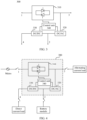
- FIG. 3 is a schematic diagram of a circuit structure of a power distribution circuit according to an embodiment of this application.
- the power distribution circuit 300 includes an alternating current input end 1, a direct current input end 2, an alternating current load input end 3, a direct current load input end 4, a switch circuit 310, a DC/AC converter 320, a DC/DC converter 330, and a control unit 340.
- the switch circuit 310 is coupled between the alternating current input end 1 and the alternating current load input end 3.
- One end of the DC/AC converter 320 is coupled to the switch circuit 310 and the alternating current load input end 3, and the other end of the DC/AC converter 320 is coupled to the direct current input end 2.
- the control unit 340 may be electrically connected to the switch circuit 310, the DC/AC converter 320, and the DC/DC converter 330.
- a switch is disposed between a mains system and the alternating current input end 1, and the switch may control the mains system to input an alternating current.
- a switch is disposed between the alternating current load input end 3 and each alternating current load, and the switch may control supply of an alternating current to each alternating current load.
- a switch is disposed between the direct current input end 2 and a battery module. The switch may control supply of a direct current to the battery module, and control the battery module to provide electric energy for a direct current load and an alternating current load.
- a switch is disposed between the direct current load input end 4 and each direct current load, and the switch may control supply of a direct current to each direct current load.
- the switch circuit 310 is configured to control the alternating current load input end 3 to output the alternating current of the mains system, and control the direct current load input end 4 to output a direct current.
- the switch circuit 310 is preferably a static transfer switch (static transfer switch, STS).
- STS static transfer switch
- the switch circuit 310 may alternatively be another type of switch. This is not limited in this application.
- the STS is a switch that automatically switches between two power supplies for power supplying. In a normal working state, if a main power supply falls within a normal voltage range, a load is connected to the main power supply. If the main power supply is abnormal, the STS automatically switches the load to a standby power supply.
- the STS automatically switches the load to the main power supply.
- the STS is in a first state only when a voltage value of an alternating current of the STS falls within a specified range, so that a voltage value of an alternating current flowing into the power distribution circuit can be limited, and stability of an alternating current input to each alternating current load can be ensured.
- the switch circuit 310 if the alternating current input by the mains system falls within the normal voltage range, the switch circuit 310 is in the first state. In other words, the alternating current input by the mains system is input to each alternating current load through the switch circuit 310, so that the mains system supplies power to the alternating current load. If the alternating current input by the mains system does not fall within the normal voltage range, the switch circuit 310 is in a second state. In other words, the switch circuit 310 is disconnected, and the mains system cannot supply power to the alternating current load.
- the DC/AC converter 320 is a converter that converts a direct current into an alternating current with a stable output voltage and a stable frequency, and converts an alternating current into a direct current with a stable output voltage.
- the DC/AC converter 320 and the battery module may form a UPS.
- the switch circuit 310 is in the second state, after the direct current of the battery module passes through the DC/AC converter 320, the DC/AC converter 320 converts the direct current into an alternating current to supply the alternating current to the alternating current load, so that the power distribution circuit 300 continuously provides electric energy for the alternating current load.
- the DC/DC converter 330 is a converter that converts a direct current into a direct current with a stable output voltage.
- the DC/DC converter 330 may convert a direct current of another voltage into a direct current of a specified threshold, to supply a direct current of a specified voltage to the direct current load.
- the control unit 340 may be a device that has a processing function, such as a digital signal processor (digital signal processing, DSP) or a system on chip (system on chip, SoC).
- the control unit 340 is configured to: monitor an electrical signal input to the switch circuit 310, an input electrical signal and/or an output electrical signal of the DC/AC converter 320, and an input electrical signal and/or an output electrical signal of the DC/DC converter 330, and send control signals to the DC/AC converter 320 and the DC/DC converter 330, so that the DC/AC converter 320 and the DC/DC converter 330 output electrical signals of specified voltages.
- an application scenario of the power distribution circuit 300 is as follows:
- the alternating current input end 1 may be electrically connected to the mains system, and is configured to receive the alternating current of the mains system.
- the alternating current load input end 3 may be electrically connected to a plurality of alternating current loads, and is configured to supply the alternating current to the alternating current loads.
- the direct current input end 2 may be electrically connected to the battery module, and is configured to receive the direct current of the battery module.
- the direct current load input end 4 may be electrically connected to a plurality of direct current loads, and is configured to supply the direct current to the direct current loads.
- the direct current input end 2 may be electrically connected to a plurality of direct current loads, and is configured to supply the direct current to the direct current loads.
- the direct current load input end 4 may be electrically connected to the battery module, and is configured to receive the direct current input by the battery module.
- the following describes a specific working process of the power distribution circuit 300 protected in this application based on the application scenario shown in FIG. 4 . It may be understood that the application scenario shown in FIG. 4 is merely an application scenario of the power distribution circuit 300, and the power distribution circuit 300 protected in this application may be further used in another scenario. This is not limited herein.
- the mains system may supply the alternating current to each alternating current load through the switch circuit 310.
- the mains system may provide electric energy for the battery module through the switch circuit 310 and the DC/AC converter 320, so that the battery module is charged.
- the mains system may supply the direct current to each direct current load through the switch circuit 310, the DC/AC converter 320, and the DC/DC converter 330.
- the control unit 340 monitors a voltage value of an alternating current input to the switch circuit 310. If the voltage value of the alternating current input to the switch circuit 310 falls within a specified range, the switch circuit 310 is in the first state. If the voltage value of the alternating current input to the switch circuit 310 does not fall within a specified range, the switch circuit 310 is in the second state. The control unit 340 may determine, based on a monitoring result, whether the switch circuit 310 is in the first state. If the control unit 340 detects that the voltage value of the alternating current input to the switch circuit 310 falls within a specified range, the switch circuit 310 is in the first state, and the control unit 340 discards monitoring data received this time or does not perform subsequent processing on the monitoring data received this time.
- the power distribution circuit 300 inputs the alternating current input by the mains system to the alternating current load, to provide electric energy for the alternating current load.
- the power distribution circuit 300 converts the alternating current input by the mains system into a direct current, and inputs the direct current to the direct current load, to provide electric energy for the direct current load.
- the control unit 340 detects that the voltage value of the alternating current input to the switch circuit 310 does not fall within the specified range, the switch circuit 310 is in the second state, and the power distribution circuit 300 stops power supplying of the mains system.
- the control unit 340 sends a control signal to the DC/AC converter 320, so that the DC/AC converter 320 converts the direct current input by the battery module into an alternating current of a specified voltage, so that the battery module supplies the alternating current to the alternating current load.
- the control unit 340 sends a control signal to the DC/DC converter 330, so that the DC/DC converter 330 converts the direct current into the direct current of the specified voltage, so that the battery module supplies the direct current to the direct current load.
- the power distribution circuit 300 provides electric energy for the direct current load and the alternating current load through the battery module, so that the power distribution circuit 300 continuously provides electric energy for the direct current load and the alternating current load.
- the specified range is a voltage value at which the switch circuit 310 is switched to the second state from the first state.
- a voltage value within the specified range is related to a rated voltage of the alternating current load. If there is no voltage conversion component between the alternating current input end 1 and the alternating current load input end 3, the voltage value within the specified range is the same as the rated voltage of the alternating current load. If there is another voltage conversion component between the alternating current input end 1 and the alternating current load input end 3, the voltage value within the specified range may be the same as or different from the rated voltage of the alternating current load.
- a voltage regulator is connected in series between the alternating current input end 1 and the alternating current load input end 3, and the voltage regulator is further electrically connected to the control unit 340.
- the control unit 340 receives the monitoring result, and determines whether the voltage value input to the switch circuit 310 is stable or whether a fluctuation amplitude falls within the specified range. If the voltage value input to the switch circuit 310 fluctuates greatly, the control unit 340 sends a control signal to the voltage regulator. After receiving the control signal, the voltage regulator converts the alternating current input by the mains system into the alternating current of the rated voltage, so that the power distribution circuit 300 supplies a stable alternating current to the alternating current load.
- the voltage regulator includes an AC/DC converter and a DC/AC converter.
- the AC/DC converter converts the alternating current input by the mains system into a direct current, and the DC/AC converter converts the direct current into an alternating current of a specified threshold. In this way, the alternating current input by the mains system is stabilized at the specified threshold, to improve stability of the alternating current.
- the control unit 340 may monitor, in real time, the voltage value of the alternating current input to the switch circuit 310. If the control unit 340 obtains, through monitoring, that the voltage value of the alternating current input to the switch circuit 310 falls within the specified range, and fluctuates within the specified range or is less than the rated voltage of the alternating current load, the control unit 340 may generate a control signal based on a difference ⁇ V between a rated voltage of each alternating current load and a voltage value at an output end of the switch circuit 310, and send the control signal to the DC/AC converter 320.
- the DC/AC converter 320 receives the control signal, and converts the direct current input by the battery module into an alternating current of a specified voltage ⁇ V.
- the alternating current output through the DC/AC converter 320 may dynamically compensate for the alternating current input by the mains system, so that the power distribution circuit 300 outputs a stable alternating current.
- the power distribution circuit after receiving the alternating current of the mains system, can provide electric energy for each alternating current load.
- the power distribution circuit may further convert the alternating current into the direct current of the specified voltage through the DC/AC converter and the DC/DC converter, and may provide electric energy for each direct current load.
- the power distribution circuit can provide electric energy for both the alternating current load and the direct current load.
- the switch circuit stops inputting of the alternating current by the mains system.
- the control unit enables the DC/AC converter to convert the direct current input by the battery module into the alternating current of the specified voltage, to supply the alternating current of the specified voltage to each alternating current load.
- the direct current input by the battery module may supply the direct current of the specified voltage to each direct current load through the DC/DC converter.
- the power distribution circuit can continuously provide electric energy for the alternating current load and the direct current load.
- the control unit may control the DC/AC converter to convert the direct current input by the battery module into the alternating current of the specified voltage.
- the alternating current output through the DC/AC converter may compensate for the alternating current input by the mains system, so that the power distribution circuit outputs a stable alternating current.
- the DC/DC converter may convert another direct current into the direct current of the rated voltage, reduce a fluctuation amplitude of the direct current, and the like, and improve stability of the direct current, to help the power distribution circuit output a stable direct current.
- the power distribution circuit 300 further includes a bypass circuit 350.
- One end of the bypass circuit 350 is electrically connected to the mains system, and the other end of the bypass circuit 350 is electrically connected to the alternating current load input end 3.
- a switch is disposed in the bypass circuit 350, and is configured to control conduction of the bypass circuit 350. If the alternating current input end 1 and the alternating current load input end 3 are disconnected, the switch in the bypass circuit 350 may be switched on.
- the alternating current input by the mains system is input to each alternating current load through the bypass circuit 350, to supply the alternating current to the alternating current load.
- the alternating current input by the mains system may be input to each direct current load through the bypass circuit 350, the DC/AC converter 320, and the DC/DC converter 330.
- the DC/AC converter 320 converts the alternating current input by the mains system into a direct current
- the DC/DC converter 330 converts the direct current into a direct current of a rated voltage of a direct current load, to supply the direct current of the rated voltage to the direct current load.
- the control unit 340 may control the battery module to perform a charging function.
- the DC/AC converter 320 converts the alternating current input by the mains system into the direct current, and the direct current is input to the battery module, so that the battery module is charged.
- an input circuit is added in this embodiment.
- the mains system may input the alternating current through the bypass circuit, thereby improving a fault tolerance rate of the power distribution circuit 300.
- FIG. 6 is a schematic diagram of a scenario in which the power distribution circuit outputs only an alternating current according to an embodiment of this application.
- the mains system may supply an alternating current to each alternating current load through the switch circuit 310. If an alternating current input by the mains system does not fall within a specified threshold range, the battery module may supply an alternating current to each alternating current load through the DC/AC converter 320.
- the control unit 340 monitors a voltage value of an alternating current input to the switch circuit 310.
- the control unit 340 may determine, based on a monitoring result, whether the switch circuit 310 is in a first state. If the control unit 340 detects that the voltage value of the alternating current input to the switch circuit 310 falls within a specified range, the switch circuit 310 is in the first state, and the control unit 340 discards monitoring data received this time or does not perform subsequent processing.
- the power distribution circuit 300 inputs the alternating current input by the mains system to the alternating current load, to provide electric energy for the alternating current load.
- the control unit 340 detects that the voltage value of the alternating current input to the switch circuit 310 does not fall within a specified range, the switch circuit 310 is in a second state, and the power distribution circuit 300 stops power supplying of the mains system.
- the control unit 340 sends a control signal to the DC/AC converter 320, the DC/AC converter 320 converts a direct current input by the battery module into an alternating current of a specified voltage, and the battery module supplies the alternating current to the alternating current load.
- the power distribution circuit 300 may provide electric energy for the alternating current load through the battery module, so that the power distribution circuit 300 continuously provides electric energy for the alternating current load.
- control unit 340 may monitor, in real time, the voltage value of the alternating current input to the switch circuit 310. If the control unit 340 obtains, through monitoring, that the voltage value of the alternating current input to the switch circuit 310 falls within the specified range and fluctuates within the specified range, the control unit 340 may generate a control signal based on a difference ⁇ V between a rated voltage of each alternating current load and a voltage value at an output end of the switch circuit 310, and send the control signal to the DC/AC converter 320.
- the DC/AC converter 320 receives the control signal, and converts the direct current input by the battery module into an alternating current of a specified voltage ⁇ V
- the alternating current output through the DC/AC converter 320 may dynamically compensate for the alternating current input by the mains system, so that the power distribution circuit 300 outputs a stable alternating current.
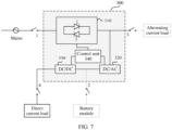
- FIG. 7 is a schematic diagram of a scenario in which the power distribution circuit outputs only a direct current according to an embodiment of this application.
- the mains system may supply a direct current to each direct current load through the switch circuit 310, the DC/AC converter 320, and the DC/DC converter 330. If an alternating current input by the mains system does not fall within a specified threshold range, the battery module may supply a direct current to each direct current load through the DC/DC converter 330.
- the control unit 340 monitors a voltage value of an alternating current input to the switch circuit 310.
- the control unit 340 may determine, based on a monitoring result, whether the switch circuit 310 is in a first state. If the control unit 340 detects that a voltage value of an electrical signal input to the switch circuit 310 falls within a specified range, the switch circuit 310 is in the first state, and the control unit 340 discards monitoring data received this time or does not perform subsequent processing.
- the alternating current input by the mains system is input to the DC/AC converter 320, and the DC/AC converter 320 converts the alternating current into a direct current, and inputs the alternating current to the DC/DC converter 330.
- the DC/DC converter 330 converts the direct current into a direct current of a specified voltage, and inputs the direct current to each direct current load, to provide electric energy for the direct current load.
- the control unit 340 detects that the voltage value of the alternating current input to the switch circuit 310 does not fall within a specified range, the switch circuit 310 is in a second state, and the power distribution circuit 300 stops power supplying of the mains system.
- the control unit 340 sends a control signal to the DC/DC converter 330, the DC/DC converter 330 converts the direct current input by the battery module into a direct current of a specified voltage, and the battery module supplies the direct current to the direct current load.
- the power distribution circuit 300 may provide electric energy for the direct current load through the battery module, so that the power distribution circuit 300 continuously provides electric energy for the direct current load.
- the DC/DC converter 330 may convert another direct current into a direct current of a rated voltage, reduce a fluctuation amplitude of the direct current, and the like, and improve stability of the direct current, to help the power distribution circuit 300 output a stable direct current.
- the power distribution circuit 300 further includes a bypass circuit 350.
- a switch in the bypass circuit 350 may be switched on.
- the alternating current input by the mains system may be input to each direct current load through the bypass circuit 350, the DC/AC converter 320, and the DC/DC converter 330.
- the DC/AC converter 320 converts the alternating current input by the mains system into the direct current
- the DC/DC converter 330 converts the direct current into a direct current of a rated voltage of a direct current load, to supply the direct current of the rated voltage to the direct current load.
- an input circuit is added in this embodiment.
- the mains system may input the alternating current through the bypass circuit, thereby improving a fault tolerance rate of the power distribution circuit 300.
- FIG. 10 is a flowchart of a method for controlling power supplying of the power distribution circuit according to an embodiment of this application. As shown in FIG. 10 , the method may be performed through the control unit 340, and a specific implementation process is as follows.
- S1001 Detect whether the switch circuit is in a first state.
- control unit is electrically connected to the switch circuit, and is configured to monitor a voltage value of an alternating current input to the switch circuit. If the voltage value of the alternating current input to the switch circuit falls within a specified range, the switch circuit is in a first state. In other words, the switch circuit is in a connected state, so that the alternating current input end 1 and the alternating current load input end 3 are connected. If the voltage value of the alternating current input to the switch circuit does not fall within a specified range, the switch circuit is in a second state. In other words, the switch circuit is in a disconnected state, so that the alternating current input end 1 and the alternating current load input end 3 are disconnected.
- an alternating current received through the alternating current input end 1 may be directly input to each alternating current load through the alternating current load input end 3, to supply the alternating current to the alternating current load.
- the control unit may send a control signal to the DC/AC converter, so that the DC/AC converter converts an alternating current output through the switch circuit into a direct current.
- the control unit sends a control signal to the DC/DC converter, so that the DC/DC converter converts the direct current output through the DC/AC converter into a direct current of a specified voltage, to supply the direct current to the direct current load.
- the alternating current input end 1 cannot supply power to an alternating current load and a direct current load.
- a direct current input through the direct current input end 2 supplies power to the alternating current load and the direct current load.
- the control unit sends a control signal to the DC/AC converter, so that the DC/AC converter converts a direct current input by the battery module into an alternating current of a specified voltage, so that the battery module supplies the alternating current to the alternating current load.
- the control unit sends a control signal to the DC/DC converter, so that the DC/DC converter converts the direct current into the direct current of the specified voltage, so that the battery module supplies the direct current to the direct current load.
- the control unit may monitor, in real time, the voltage value of the alternating current input to the switch circuit. If the control unit obtains, through monitoring, that the voltage value of the alternating current input to the switch circuit falls within the specified range and fluctuates within the specified range, the control unit may generate a control signal based on a difference between a rated voltage of each alternating current load and a voltage value at an output end of the switch circuit, and send the control signal to the DC/AC converter.
- the DC/AC converter receives the control signal, and converts the direct current input by the battery module into an alternating current of a specified difference voltage.
- the alternating current output through the DC/AC converter may dynamically compensate for the alternating current input by the mains system, so that the power distribution circuit outputs a stable alternating current.
- the power distribution circuit after receiving the alternating current of the mains system, can provide electric energy for each alternating current load.
- the control unit may send the control signals to the DC/AC converter and the DC/DC converter, the DC/AC converter converts the received alternating current into the direct current, and the DC/DC converter converts the direct current output through the DC/AC converter into the direct current of the specified voltage, to provide electric energy for each direct current load.
- the power distribution circuit provides electric energy for both the alternating current load and the direct current load.
- the switch circuit stops inputting of the alternating current by the mains system.
- the control unit enables the DC/AC converter to convert the direct current input by the battery module into the alternating current of the specified voltage, to supply the alternating current of the specified voltage to each alternating current load.
- the direct current input by the battery module may supply the direct current of the specified voltage to each direct current load through the DC/DC converter.
- the power distribution circuit continuously provides electric energy for the alternating current load and the direct current load.
- the power supply system includes a power distribution circuit, an alternating current power supply, a direct current power supply, at least one alternating current load, and at least one direct current load.
- the alternating current power supply is coupled to an alternating current input end in the power distribution circuit, and is configured to supply an alternating current.
- the direct current power supply is coupled to a direct current input end in the power distribution circuit, and is configured to supply a direct current.
- the at least one alternating current load is coupled to an alternating current load input end of the power distribution circuit, and is configured to receive an alternating current.
- the at least one direct current load is coupled to a direct current load input end of the power distribution circuit, and is configured to receive a direct current.
- the power distribution circuit may be the power distribution circuit recorded in FIG. 3 to FIG. 9 and the foregoing corresponding protection solution. Because the power supply system includes the power distribution circuit, the power supply system has all or at least some advantages of the power distribution circuit.
- the power supply system may be used in power-consuming devices such as a data center, an outdoor cabinet, and a base station, or may be used in a home power supply system, a factory power supply system, or another power supply system. This is not limited in this application.
- a quantity of components, a type of components, and the like in the power distribution circuit provided in embodiments of this application are not limited to the foregoing embodiments. All technical solutions implemented according to principles of this application fall within the protection scope of this solution. Technical solutions in which any one or more embodiments or figures in the specification are combined in a proper manner shall fall within the protection scope of this solution.
Landscapes
- Engineering & Computer Science (AREA)
- Power Engineering (AREA)
- Business, Economics & Management (AREA)
- Emergency Management (AREA)
- Stand-By Power Supply Arrangements (AREA)
- Direct Current Feeding And Distribution (AREA)
Abstract
Description
- This application claims priority to
Chinese Patent Application No. 202210501244.2, filed with the China National Intellectual Property Administration on May 10, 2022 - The present invention relates to the field of power supply technologies, and in particular, to a power distribution circuit, a method for controlling power supplying of the power distribution circuit, and a power supply system.
- Power-consuming devices such as a data center, an outdoor cabinet, and a base station are generally connected to a power supply through power distribution circuits. The power distribution circuit may convert an alternating current provided by a mains system into a direct current, to supply the direct current to the power-consuming device. Alternatively, the power distribution circuit may convert a direct current provided by a power storage battery into an alternating current, to supply the alternating current to the power-consuming device.
- An uninterruptible power system (uninterruptible power system, UPS) is generally further configured in a conventional power distribution circuit. When an external power supply cannot supply power to the power-consuming device, the power distribution circuit can invoke the UPS to supply power to the power-consuming device. However, the conventional power distribution circuit can output only an alternating current or a direct current, and cannot provide electric energy for both an alternating current load and a direct current load. As a result, an application scope of the power distribution circuit is small, and a power supply manner is not flexible.
- To resolve the foregoing problem, embodiments of this application provide a power distribution circuit, a method for controlling power supplying of the power distribution circuit, and a power supply system. The power distribution circuit is electrically connected to a mains system and a battery module. When the mains system supplies power normally, the power distribution circuit may convert an alternating current power input by the mains system into a stable direct current and a stable alternating current, to provide stable electrical signals for an alternating current load and a direct current load. When the mains system is abnormal, the power distribution circuit may convert a direct current input by the battery module into a stable direct current and a stable alternating current, to provide stable electrical signals for an alternating current load and a direct current load.
- In view of this, the following technical solutions are used in embodiments of this application.
- According to a first aspect, this application provides a power distribution circuit, including: an alternating current input end, a direct current input end, an alternating current load input end, a direct current load input end, a switch circuit, a direct current/alternating current converter, a direct current/direct current converter, and a control unit. The switch circuit is coupled between the alternating current input end and the alternating current load input end, and is configured to control the alternating current load input end to output an alternating current input through the alternating current input end. One end of the direct current/alternating current converter is coupled to the switch circuit and the alternating current load input end, the other end of the direct current/alternating current converter is coupled to the direct current input end and the direct current/direct current converter, and the direct current/altemating current converter is configured to perform conversion on a direct current and an alternating current. One end of the direct current/direct current converter is coupled to the direct current/altemating current converter and the direct current input end, the other end of the direct current/direct current converter is coupled to the direct current load input end, and the direct current/direct current converter is configured to perform direct current conversion on an input direct current. The control unit is electrically connected to the switch circuit, the direct current/alternating current converter, and the direct current/direct current converter, and is configured to: detect a status of the switch circuit; and when the switch circuit is in a first state, send a first control signal to the direct current/alternating current converter and send a second control signal to the direct current/direct current converter, where the first state is a state in which the switch circuit enables the alternating current input end and the alternating current load input end to be connected, the first control signal indicates the direct current/alternating current converter to convert the alternating current input through the alternating current input end into a direct current, and the second control signal indicates the direct current/direct current converter to perform direct current conversion on a direct current output through the direct current/altemating current converter.
- In this implementation, after receiving an alternating current of a mains system, the power distribution circuit can provide electric energy for each alternating current load. The control unit in the power distribution circuit may work through the DC/AC converter and the DC/DC converter, the DC/AC converter converts the alternating current into the direct current, and the DC/DC converter converts the direct current into a direct current of a specified voltage, to provide electric energy for each direct current load. The power distribution circuit can provide electric energy for both the alternating current load and the direct current load.
- In an implementation, the control unit is further configured to: when the switch circuit is in a second state, send a third control signal to the direct current/alternating current converter and send a fourth control signal to the direct current/direct current converter, where the second state is a state in which the switch circuit enables the alternating current input end and the alternating current load input end to be disconnected, the third control signal indicates the direct current/alternating current converter to convert a direct current input through the direct current input end into an alternating current, and the second control signal indicates the direct current/direct current converter to perform direct current conversion on the direct current input through the direct current input end.
- In this implementation, if the alternating current input by the mains system is abnormal, the switch circuit stops inputting of the alternating current by the mains system. The control unit enables the DC/AC converter to convert the direct current input through the direct current input end into an alternating current of a specified voltage, to supply an alternating current of a specified voltage to each alternating current load. The direct current input through the direct current input end may supply a direct current of a specified voltage to each direct current load through the DC/DC converter. The power distribution circuit can continuously provide electric energy for the alternating current load and the direct current load.
- In one implementation, the switch circuit is a static transfer switch.
- In this implementation, the static transfer switch is a switch that is switched on only when an input voltage falls within a specified range. Only when a voltage of the alternating current input through the alternating current input end falls within a specified range, the alternating current is input to the alternating current load through the alternating current load input end, to ensure stability of an alternating current output through the alternating current load input end.
- In an implementation, the control unit is specifically configured to: monitor the voltage of the alternating current input through the alternating current input end; and when the voltage of the alternating current input through the alternating current input end falls within the specified range, determine that the switch circuit is in the first state; or when the voltage of the alternating current input through the alternating current input end does not fall within the specified range, determine that the switch circuit is in the second state.
- In an implementation, the control unit is further configured to: monitor the voltage of the alternating current input through the alternating current input end; and when the voltage of the alternating current input through the alternating current input end falls within the specified range and is less than a specified threshold, send a fifth control signal to the direct current/alternating current converter, where the fifth control signal indicates the direct current/alternating current converter to convert the direct current input through the direct current input end into an alternating current of a specified voltage, and the specified voltage is a difference between the specified threshold and the voltage of the alternating current input through the alternating current input end.
- In this implementation, if the alternating current input through the alternating current input end is unstable or is lower than a rated voltage of an alternating current load, the control unit may generate a control signal based on a difference between the rated voltage of each alternating current load and a voltage value of the input alternating current, and send the control signal to the DC/AC converter. The DC/AC converter may convert the direct current input through the direct current input end into an alternating current of a specified voltage. The alternating current output through the DC/AC converter may dynamically compensate for the alternating current input by the mains system, so that the power distribution circuit outputs a stable alternating current.
- In an implementation, the power distribution circuit further includes a voltage regulator, coupled between the alternating current input end and the alternating current load input end, and configured to convert the alternating current output through the alternating current load input end into an alternating current of the specified threshold.
- In this implementation, the voltage regulator is connected between the alternating current input end and the alternating current load input end, so that the alternating current input through the alternating current input end can be stabilized at the specified voltage, and stability of the alternating current output by the power distribution circuit can be improved.
- In an implementation, the power distribution circuit further includes: a bypass circuit, coupled between the alternating current input end and the alternating current load input end, and configured to: when a circuit in which the switch circuit is located is disconnected, control the alternating current load input end to output the alternating current input through the alternating current input end, and/or control the direct current load input end to output a direct current.
- In an implementation, the bypass circuit is connected between the alternating current input end and the alternating current load input end. When the circuit in which the switch circuit is located is short-circuited, the alternating current input through the alternating current input end is input to the alternating current load through the bypass circuit, thereby improving a fault tolerance rate of the power distribution circuit.
- According to a second aspect, this application provides a method for controlling power supplying of a power distribution circuit. The method includes: detecting whether a switch circuit is in a first state, where the first state is a state in which the switch circuit enables an alternating current input end and an alternating current load input end to be connected; and when the switch circuit is in the first state, sending a first control signal to a direct current/alternating current converter and sending a second control signal to a direct current/direct current converter, where the first control signal indicates the direct current/alternating current converter to convert an alternating current input through the alternating current input end into a direct current, and the second control signal indicates the direct current/direct current converter to perform direct current conversion on a direct current output through the direct current/altemating current converter.
- In an implementation, the method further includes: when the switch circuit is not in the first state, sending a third control signal to the direct current/alternating current converter and sending a fourth control signal to the direct current/direct current converter, where the third control signal indicates the direct current/altemating current converter to convert a direct current input through the direct current input end into an alternating current, and the second control signal indicates the direct current/direct current converter to perform direct current conversion on the direct current input through the direct current input end.
- In an implementation, the detecting whether a switch circuit is in a first state includes: monitoring a voltage of the alternating current input through the alternating current input end; and when the voltage of the alternating current input through the alternating current input end falls within a specified range, determining that the switch circuit is in the first state; or when the voltage of the alternating current input through the alternating current input end does not fall within a specified range, determining that the switch circuit is not in the first state.
- In an implementation, the method further includes: monitoring the voltage of the alternating current input through the alternating current input end; and when the voltage of the alternating current input through the alternating current input end falls within the specified range and is less than a specified threshold, sending a fifth control signal to the direct current/alternating current converter, where the fifth control signal indicates the direct current/alternating current converter to convert the direct current input through the direct current input end into an alternating current of a specified voltage, and the specified voltage is a difference between the specified threshold and the voltage of the alternating current input through the alternating current input end.
- According to a third aspect, this application provides a power supply system, including: the power distribution circuit according to the implementations of the first aspect; an alternating current power supply, coupled to the alternating current input end in the power distribution circuit, and configured to supply an alternating current; a direct current power supply, coupled to the direct current input end in the power distribution circuit, and configured to supply a direct current; at least one alternating current load, coupled to the alternating current load input end of the power distribution circuit, and configured to receive an alternating current; and at least one direct current load, coupled to the direct current load input end of the power distribution circuit, and configured to receive a direct current.
- The following briefly describes accompanying drawings required for describing embodiments or a conventional technology.
-
FIG. 1 is a schematic diagram of a circuit structure of a power distribution circuit in a conventional technology; -
FIG. 2 is a schematic diagram of a circuit structure of another power distribution circuit in a conventional technology; -
FIG. 3 is a schematic diagram of a circuit structure of a power distribution circuit according to an embodiment of this application; -
FIG. 4 is a schematic diagram of an application scenario of a power distribution circuit according to an embodiment of this application; -
FIG. 5 is a schematic diagram of a circuit structure of another power distribution circuit according to an embodiment of this application; -
FIG. 6 is a schematic diagram of a scenario in which a power distribution circuit outputs only an alternating current according to an embodiment of this application; -
FIG. 7 is a schematic diagram of a scenario in which a power distribution circuit outputs only a direct current according to an embodiment of this application; -
FIG. 8 is a schematic diagram of a scenario in which another power distribution circuit outputs only a direct current according to an embodiment of this application; -
FIG. 9 is a schematic diagram of a scenario in which another power distribution circuit outputs only a direct current according to an embodiment of this application; and -
FIG. 10 is a flowchart of a method for controlling power supplying of a power distribution circuit according to an embodiment of this application. - The following describes the technical solutions in embodiments of this application with reference to the accompanying drawings in embodiments of this application.
- The term "and/or" in this specification describes an association relationship between associated objects and indicates that three relationships may exist. For example, A and/or B may indicate the following three cases: Only A exists, both A and B exist, and only B exists. The character "/" in this specification indicates an "or" relationship between the associated objects. For example, A/B indicates A or B.
- In the specification and claims of this application, the terms "first", "second", and the like are intended to distinguish between different objects, but do not indicate a particular order of the objects. For example, a first response message, a second response message, and the like are used to distinguish between different response messages, but do not indicate a particular order of the response messages.
- In addition, in embodiments of this application, the word "example" or "for example" is used to indicate giving an example, an illustration, or a description. Any embodiment or design scheme described as an "example" or "for example" in embodiments of this application should not be explained as being more preferred or having more advantages than another embodiment or design scheme. Exactly, use of the term "example", "for example", or the like is intended to present a related concept in a specific manner.
- In the description of embodiments of this application, unless otherwise specified, "a plurality of" means two or more. For example, a plurality of control units means two or more control units, and a plurality of elements means two or more elements.
-
FIG. 1 is a schematic diagram of a circuit structure of a power distribution circuit in a conventional technology. As shown inFIG. 1 , thepower distribution circuit 100 includes aswitch circuit 110, an alternating current/direct current (alternating current/directing current, AC/DC)converter 120, a direct current/alternating current (directing current/alternating current, DC/AC)converter 130, and a direct current/directing current (directing current/directing current, DC/DC)converter 140. The AC/DC converter 120 is connected in series with the DC/AC converter 130. The other end of the AC/DC converter 120 serves as aninput end 1, and is electrically connected to a mains system. The other end of the DC/AC converter 130 serves as anoutput end 2, and is electrically connected to each load. One end of the DC/DC converter 140 is electrically connected between the AC/DC converter 120 and the DC/AC converter 130; and the other end of the DC/DC converter 140 serves as aninput end 3, and is electrically connected to a battery module, to form a UPS. Two ends of theswitch circuit 110 are electrically connected to theinput end 1 and theoutput end 2 respectively. - In the conventional technology, when the mains system supplies power normally, an alternating current input by the mains system may directly provide electric energy for each alternating current load through the
switch circuit 110. The alternating current input by the mains system may be converted through the AC/DC converter 120 and the DC/AC converter 130, to obtain a stable alternating current, so as to supply the stable alternating current to the alternating current load. When the mains system is abnormal, the alternating current load is powered by the battery module. A direct current input by the battery module passes through the DC/DC converter 140 to obtain a stable direct current, and then the stable direct current is converted through the DC/AC converter 130, to supply a stable alternating current to the alternating current load. However, the conventionalpower distribution circuit 100 can output only the stable alternating current, but cannot output a stable direct current. -
FIG. 2 is a schematic diagram of a circuit structure of a power distribution circuit in a conventional technology. As shown inFIG. 2 , thepower distribution circuit 200 includes an AC/DC converter 210 and a DC/DC converter 220. The AC/DC converter 210 is connected in series with the DC/DC converter 220. The other end of the AC/DC converter 210 serves as aninput end 1, and is electrically connected to a mains system. The other end of the DC/DC converter 220 may serve as anoutput end 2 and aninput end 3. Theoutput end 2 is electrically connected to each load. Theinput end 3 is electrically connected to a battery module. - In the conventional technology, when the mains system supplies power normally, an alternating current input by the mains system is converted through the AC/
DC converter 210 and the DC/DC converter 220, to obtain a stable direct current, so as to supply a stable alternating current to a direct current load. When the mains system is abnormal, the direct current load is powered by the battery module. However, the conventionalpower distribution circuit 200 can output only the stable direct current, but cannot output a stable alternating current. - To overcome disadvantages in the conventional technology, a power distribution circuit is designed in this application. The power distribution circuit is electrically connected to a mains system and a battery module. When the mains system supplies power normally, the power distribution circuit may convert an alternating current power input by the mains system into a stable direct current and a stable alternating current, to provide stable electrical signals for an alternating current load and a direct current load. When the mains system is abnormal, the power distribution circuit may convert a direct current input by the battery module into a stable direct current and a stable alternating current, to provide stable electrical signals for an alternating current load and a direct current load. Compared with the conventional power distribution circuit, the power distribution circuit protected in this application can provide the stable electrical signals for both the direct current load and the alternating current load, thereby improving an application scenario of the power distribution circuit.
-
FIG. 3 is a schematic diagram of a circuit structure of a power distribution circuit according to an embodiment of this application. As shown inFIG. 3 , thepower distribution circuit 300 includes an alternatingcurrent input end 1, a directcurrent input end 2, an alternating currentload input end 3, a direct currentload input end 4, aswitch circuit 310, a DC/AC converter 320, a DC/DC converter 330, and acontrol unit 340. Theswitch circuit 310 is coupled between the alternatingcurrent input end 1 and the alternating currentload input end 3. One end of the DC/AC converter 320 is coupled to theswitch circuit 310 and the alternating currentload input end 3, and the other end of the DC/AC converter 320 is coupled to the directcurrent input end 2. One end of the DC/DC converter 330 is coupled to the DC/AC converter 320 and the directcurrent input end 2, and the other end of the DC/DC converter 330 is coupled to the direct currentload input end 4. Thecontrol unit 340 may be electrically connected to theswitch circuit 310, the DC/AC converter 320, and the DC/DC converter 330. - In this application, a switch is disposed between a mains system and the alternating
current input end 1, and the switch may control the mains system to input an alternating current. A switch is disposed between the alternating currentload input end 3 and each alternating current load, and the switch may control supply of an alternating current to each alternating current load. A switch is disposed between the directcurrent input end 2 and a battery module. The switch may control supply of a direct current to the battery module, and control the battery module to provide electric energy for a direct current load and an alternating current load. A switch is disposed between the direct currentload input end 4 and each direct current load, and the switch may control supply of a direct current to each direct current load. - The
switch circuit 310 is configured to control the alternating currentload input end 3 to output the alternating current of the mains system, and control the direct currentload input end 4 to output a direct current. In this application, theswitch circuit 310 is preferably a static transfer switch (static transfer switch, STS). Certainly, theswitch circuit 310 may alternatively be another type of switch. This is not limited in this application. The STS is a switch that automatically switches between two power supplies for power supplying. In a normal working state, if a main power supply falls within a normal voltage range, a load is connected to the main power supply. If the main power supply is abnormal, the STS automatically switches the load to a standby power supply. If the main power supply returns to the normal state, the STS automatically switches the load to the main power supply. In this application, the STS is in a first state only when a voltage value of an alternating current of the STS falls within a specified range, so that a voltage value of an alternating current flowing into the power distribution circuit can be limited, and stability of an alternating current input to each alternating current load can be ensured. - In this application, if the alternating current input by the mains system falls within the normal voltage range, the
switch circuit 310 is in the first state. In other words, the alternating current input by the mains system is input to each alternating current load through theswitch circuit 310, so that the mains system supplies power to the alternating current load. If the alternating current input by the mains system does not fall within the normal voltage range, theswitch circuit 310 is in a second state. In other words, theswitch circuit 310 is disconnected, and the mains system cannot supply power to the alternating current load. - The DC/
AC converter 320 is a converter that converts a direct current into an alternating current with a stable output voltage and a stable frequency, and converts an alternating current into a direct current with a stable output voltage. Optionally, as shown inFIG. 3 , if the directcurrent input end 2 is electrically connected to the battery module, the DC/AC converter 320 and the battery module may form a UPS. When theswitch circuit 310 is in the second state, after the direct current of the battery module passes through the DC/AC converter 320, the DC/AC converter 320 converts the direct current into an alternating current to supply the alternating current to the alternating current load, so that thepower distribution circuit 300 continuously provides electric energy for the alternating current load. - The DC/
DC converter 330 is a converter that converts a direct current into a direct current with a stable output voltage. Optionally, as shown inFIG. 3 , if the direct currentload input end 4 is electrically connected to each direct current load, the DC/DC converter 330 may convert a direct current of another voltage into a direct current of a specified threshold, to supply a direct current of a specified voltage to the direct current load. - The
control unit 340 may be a device that has a processing function, such as a digital signal processor (digital signal processing, DSP) or a system on chip (system on chip, SoC). In this application, thecontrol unit 340 is configured to: monitor an electrical signal input to theswitch circuit 310, an input electrical signal and/or an output electrical signal of the DC/AC converter 320, and an input electrical signal and/or an output electrical signal of the DC/DC converter 330, and send control signals to the DC/AC converter 320 and the DC/DC converter 330, so that the DC/AC converter 320 and the DC/DC converter 330 output electrical signals of specified voltages. - As shown in
FIG. 4 , an application scenario of thepower distribution circuit 300 is as follows: The alternatingcurrent input end 1 may be electrically connected to the mains system, and is configured to receive the alternating current of the mains system. The alternating currentload input end 3 may be electrically connected to a plurality of alternating current loads, and is configured to supply the alternating current to the alternating current loads. The directcurrent input end 2 may be electrically connected to the battery module, and is configured to receive the direct current of the battery module. The direct currentload input end 4 may be electrically connected to a plurality of direct current loads, and is configured to supply the direct current to the direct current loads. In an example, the directcurrent input end 2 may be electrically connected to a plurality of direct current loads, and is configured to supply the direct current to the direct current loads. The direct currentload input end 4 may be electrically connected to the battery module, and is configured to receive the direct current input by the battery module. - The following describes a specific working process of the
power distribution circuit 300 protected in this application based on the application scenario shown inFIG. 4 . It may be understood that the application scenario shown inFIG. 4 is merely an application scenario of thepower distribution circuit 300, and thepower distribution circuit 300 protected in this application may be further used in another scenario. This is not limited herein. - As shown in
FIG. 4 , if the alternating current input by the mains system falls within a specified threshold range, the mains system may supply the alternating current to each alternating current load through theswitch circuit 310. The mains system may provide electric energy for the battery module through theswitch circuit 310 and the DC/AC converter 320, so that the battery module is charged. The mains system may supply the direct current to each direct current load through theswitch circuit 310, the DC/AC converter 320, and the DC/DC converter 330. - The
control unit 340 monitors a voltage value of an alternating current input to theswitch circuit 310. If the voltage value of the alternating current input to theswitch circuit 310 falls within a specified range, theswitch circuit 310 is in the first state. If the voltage value of the alternating current input to theswitch circuit 310 does not fall within a specified range, theswitch circuit 310 is in the second state. Thecontrol unit 340 may determine, based on a monitoring result, whether theswitch circuit 310 is in the first state. If thecontrol unit 340 detects that the voltage value of the alternating current input to theswitch circuit 310 falls within a specified range, theswitch circuit 310 is in the first state, and thecontrol unit 340 discards monitoring data received this time or does not perform subsequent processing on the monitoring data received this time. Thepower distribution circuit 300 inputs the alternating current input by the mains system to the alternating current load, to provide electric energy for the alternating current load. Thepower distribution circuit 300 converts the alternating current input by the mains system into a direct current, and inputs the direct current to the direct current load, to provide electric energy for the direct current load. - If the
control unit 340 detects that the voltage value of the alternating current input to theswitch circuit 310 does not fall within the specified range, theswitch circuit 310 is in the second state, and thepower distribution circuit 300 stops power supplying of the mains system. Thecontrol unit 340 sends a control signal to the DC/AC converter 320, so that the DC/AC converter 320 converts the direct current input by the battery module into an alternating current of a specified voltage, so that the battery module supplies the alternating current to the alternating current load. Thecontrol unit 340 sends a control signal to the DC/DC converter 330, so that the DC/DC converter 330 converts the direct current into the direct current of the specified voltage, so that the battery module supplies the direct current to the direct current load. When the mains system is abnormal, thepower distribution circuit 300 provides electric energy for the direct current load and the alternating current load through the battery module, so that thepower distribution circuit 300 continuously provides electric energy for the direct current load and the alternating current load. - The specified range is a voltage value at which the
switch circuit 310 is switched to the second state from the first state. A voltage value within the specified range is related to a rated voltage of the alternating current load. If there is no voltage conversion component between the alternatingcurrent input end 1 and the alternating currentload input end 3, the voltage value within the specified range is the same as the rated voltage of the alternating current load. If there is another voltage conversion component between the alternatingcurrent input end 1 and the alternating currentload input end 3, the voltage value within the specified range may be the same as or different from the rated voltage of the alternating current load. - Optionally, a voltage regulator is connected in series between the alternating
current input end 1 and the alternating currentload input end 3, and the voltage regulator is further electrically connected to thecontrol unit 340. Thecontrol unit 340 receives the monitoring result, and determines whether the voltage value input to theswitch circuit 310 is stable or whether a fluctuation amplitude falls within the specified range. If the voltage value input to theswitch circuit 310 fluctuates greatly, thecontrol unit 340 sends a control signal to the voltage regulator. After receiving the control signal, the voltage regulator converts the alternating current input by the mains system into the alternating current of the rated voltage, so that thepower distribution circuit 300 supplies a stable alternating current to the alternating current load. In an example, the voltage regulator includes an AC/DC converter and a DC/AC converter. The AC/DC converter converts the alternating current input by the mains system into a direct current, and the DC/AC converter converts the direct current into an alternating current of a specified threshold. In this way, the alternating current input by the mains system is stabilized at the specified threshold, to improve stability of the alternating current. - The
control unit 340 may monitor, in real time, the voltage value of the alternating current input to theswitch circuit 310. If thecontrol unit 340 obtains, through monitoring, that the voltage value of the alternating current input to theswitch circuit 310 falls within the specified range, and fluctuates within the specified range or is less than the rated voltage of the alternating current load, thecontrol unit 340 may generate a control signal based on a difference ΔV between a rated voltage of each alternating current load and a voltage value at an output end of theswitch circuit 310, and send the control signal to the DC/AC converter 320. The DC/AC converter 320 receives the control signal, and converts the direct current input by the battery module into an alternating current of a specified voltage ΔV. The alternating current output through the DC/AC converter 320 may dynamically compensate for the alternating current input by the mains system, so that thepower distribution circuit 300 outputs a stable alternating current. - In this embodiment of this application, after receiving the alternating current of the mains system, the power distribution circuit can provide electric energy for each alternating current load. The power distribution circuit may further convert the alternating current into the direct current of the specified voltage through the DC/AC converter and the DC/DC converter, and may provide electric energy for each direct current load. The power distribution circuit can provide electric energy for both the alternating current load and the direct current load.
- If the alternating current input by the mains system is abnormal, the switch circuit stops inputting of the alternating current by the mains system. The control unit enables the DC/AC converter to convert the direct current input by the battery module into the alternating current of the specified voltage, to supply the alternating current of the specified voltage to each alternating current load. The direct current input by the battery module may supply the direct current of the specified voltage to each direct current load through the DC/DC converter. The power distribution circuit can continuously provide electric energy for the alternating current load and the direct current load.
- If the alternating current input by the mains system is unstable, the control unit may control the DC/AC converter to convert the direct current input by the battery module into the alternating current of the specified voltage. The alternating current output through the DC/AC converter may compensate for the alternating current input by the mains system, so that the power distribution circuit outputs a stable alternating current. The DC/DC converter may convert another direct current into the direct current of the rated voltage, reduce a fluctuation amplitude of the direct current, and the like, and improve stability of the direct current, to help the power distribution circuit output a stable direct current.
- As shown in
FIG. 5 , thepower distribution circuit 300 further includes abypass circuit 350. One end of thebypass circuit 350 is electrically connected to the mains system, and the other end of thebypass circuit 350 is electrically connected to the alternating currentload input end 3. A switch is disposed in thebypass circuit 350, and is configured to control conduction of thebypass circuit 350. If the alternatingcurrent input end 1 and the alternating currentload input end 3 are disconnected, the switch in thebypass circuit 350 may be switched on. The alternating current input by the mains system is input to each alternating current load through thebypass circuit 350, to supply the alternating current to the alternating current load. - The alternating current input by the mains system may be input to each direct current load through the
bypass circuit 350, the DC/AC converter 320, and the DC/DC converter 330. The DC/AC converter 320 converts the alternating current input by the mains system into a direct current, and the DC/DC converter 330 converts the direct current into a direct current of a rated voltage of a direct current load, to supply the direct current of the rated voltage to the direct current load. Optionally, thecontrol unit 340 may control the battery module to perform a charging function. The DC/AC converter 320 converts the alternating current input by the mains system into the direct current, and the direct current is input to the battery module, so that the battery module is charged. - Compared with the solution shown in
FIG. 4 , in this solution, an input circuit is added in this embodiment. When a circuit in which theswitch circuit 310 is located is short-circuited, the mains system may input the alternating current through the bypass circuit, thereby improving a fault tolerance rate of thepower distribution circuit 300. -
FIG. 6 is a schematic diagram of a scenario in which the power distribution circuit outputs only an alternating current according to an embodiment of this application. As shown inFIG. 6 , the mains system may supply an alternating current to each alternating current load through theswitch circuit 310. If an alternating current input by the mains system does not fall within a specified threshold range, the battery module may supply an alternating current to each alternating current load through the DC/AC converter 320. - The
control unit 340 monitors a voltage value of an alternating current input to theswitch circuit 310. Thecontrol unit 340 may determine, based on a monitoring result, whether theswitch circuit 310 is in a first state. If thecontrol unit 340 detects that the voltage value of the alternating current input to theswitch circuit 310 falls within a specified range, theswitch circuit 310 is in the first state, and thecontrol unit 340 discards monitoring data received this time or does not perform subsequent processing. Thepower distribution circuit 300 inputs the alternating current input by the mains system to the alternating current load, to provide electric energy for the alternating current load. - If the
control unit 340 detects that the voltage value of the alternating current input to theswitch circuit 310 does not fall within a specified range, theswitch circuit 310 is in a second state, and thepower distribution circuit 300 stops power supplying of the mains system. Thecontrol unit 340 sends a control signal to the DC/AC converter 320, the DC/AC converter 320 converts a direct current input by the battery module into an alternating current of a specified voltage, and the battery module supplies the alternating current to the alternating current load. In this application, if the mains system is abnormal, thepower distribution circuit 300 may provide electric energy for the alternating current load through the battery module, so that thepower distribution circuit 300 continuously provides electric energy for the alternating current load. - Optionally, the
control unit 340 may monitor, in real time, the voltage value of the alternating current input to theswitch circuit 310. If thecontrol unit 340 obtains, through monitoring, that the voltage value of the alternating current input to theswitch circuit 310 falls within the specified range and fluctuates within the specified range, thecontrol unit 340 may generate a control signal based on a difference ΔV between a rated voltage of each alternating current load and a voltage value at an output end of theswitch circuit 310, and send the control signal to the DC/AC converter 320. The DC/AC converter 320 receives the control signal, and converts the direct current input by the battery module into an alternating current of a specified voltage ΔV The alternating current output through the DC/AC converter 320 may dynamically compensate for the alternating current input by the mains system, so that thepower distribution circuit 300 outputs a stable alternating current. -
FIG. 7 is a schematic diagram of a scenario in which the power distribution circuit outputs only a direct current according to an embodiment of this application. As shown inFIG. 7 , the mains system may supply a direct current to each direct current load through theswitch circuit 310, the DC/AC converter 320, and the DC/DC converter 330. If an alternating current input by the mains system does not fall within a specified threshold range, the battery module may supply a direct current to each direct current load through the DC/DC converter 330. - The
control unit 340 monitors a voltage value of an alternating current input to theswitch circuit 310. Thecontrol unit 340 may determine, based on a monitoring result, whether theswitch circuit 310 is in a first state. If thecontrol unit 340 detects that a voltage value of an electrical signal input to theswitch circuit 310 falls within a specified range, theswitch circuit 310 is in the first state, and thecontrol unit 340 discards monitoring data received this time or does not perform subsequent processing. The alternating current input by the mains system is input to the DC/AC converter 320, and the DC/AC converter 320 converts the alternating current into a direct current, and inputs the alternating current to the DC/DC converter 330. The DC/DC converter 330 converts the direct current into a direct current of a specified voltage, and inputs the direct current to each direct current load, to provide electric energy for the direct current load. - As shown in
FIG. 8 , if thecontrol unit 340 detects that the voltage value of the alternating current input to theswitch circuit 310 does not fall within a specified range, theswitch circuit 310 is in a second state, and thepower distribution circuit 300 stops power supplying of the mains system. Thecontrol unit 340 sends a control signal to the DC/DC converter 330, the DC/DC converter 330 converts the direct current input by the battery module into a direct current of a specified voltage, and the battery module supplies the direct current to the direct current load. In this application, if the mains system is abnormal, thepower distribution circuit 300 may provide electric energy for the direct current load through the battery module, so that thepower distribution circuit 300 continuously provides electric energy for the direct current load. - In this application, the DC/
DC converter 330 may convert another direct current into a direct current of a rated voltage, reduce a fluctuation amplitude of the direct current, and the like, and improve stability of the direct current, to help thepower distribution circuit 300 output a stable direct current. - As shown in
FIG. 9 , thepower distribution circuit 300 further includes abypass circuit 350. When the alternatingcurrent input end 1 and the alternating currentload input end 3 are disconnected, a switch in thebypass circuit 350 may be switched on. The alternating current input by the mains system may be input to each direct current load through thebypass circuit 350, the DC/AC converter 320, and the DC/DC converter 330. The DC/AC converter 320 converts the alternating current input by the mains system into the direct current, and the DC/DC converter 330 converts the direct current into a direct current of a rated voltage of a direct current load, to supply the direct current of the rated voltage to the direct current load. - Compared with the solution shown in
FIG. 7 , in this solution, an input circuit is added in this embodiment. When a circuit in which theswitch circuit 310 is located is short-circuited, the mains system may input the alternating current through the bypass circuit, thereby improving a fault tolerance rate of thepower distribution circuit 300. -
FIG. 10 is a flowchart of a method for controlling power supplying of the power distribution circuit according to an embodiment of this application. As shown inFIG. 10 , the method may be performed through thecontrol unit 340, and a specific implementation process is as follows. - S1001: Detect whether the switch circuit is in a first state.
- Specifically, the control unit is electrically connected to the switch circuit, and is configured to monitor a voltage value of an alternating current input to the switch circuit. If the voltage value of the alternating current input to the switch circuit falls within a specified range, the switch circuit is in a first state. In other words, the switch circuit is in a connected state, so that the alternating
current input end 1 and the alternating currentload input end 3 are connected. If the voltage value of the alternating current input to the switch circuit does not fall within a specified range, the switch circuit is in a second state. In other words, the switch circuit is in a disconnected state, so that the alternatingcurrent input end 1 and the alternating currentload input end 3 are disconnected. - S1002: When the switch circuit is in the first state, send a first control signal to the direct current/altemating current converter and send a second control signal to the direct current/direct current converter.
- Specifically, if the switch circuit is in the first state, an alternating current received through the alternating
current input end 1 may be directly input to each alternating current load through the alternating currentload input end 3, to supply the alternating current to the alternating current load. To supply power to a direct current load at the same time, the control unit may send a control signal to the DC/AC converter, so that the DC/AC converter converts an alternating current output through the switch circuit into a direct current. The control unit sends a control signal to the DC/DC converter, so that the DC/DC converter converts the direct current output through the DC/AC converter into a direct current of a specified voltage, to supply the direct current to the direct current load. - If the switch circuit is in the second state, the alternating
current input end 1 cannot supply power to an alternating current load and a direct current load. In this case, a direct current input through the directcurrent input end 2 supplies power to the alternating current load and the direct current load. The control unit sends a control signal to the DC/AC converter, so that the DC/AC converter converts a direct current input by the battery module into an alternating current of a specified voltage, so that the battery module supplies the alternating current to the alternating current load. The control unit sends a control signal to the DC/DC converter, so that the DC/DC converter converts the direct current into the direct current of the specified voltage, so that the battery module supplies the direct current to the direct current load. - The control unit may monitor, in real time, the voltage value of the alternating current input to the switch circuit. If the control unit obtains, through monitoring, that the voltage value of the alternating current input to the switch circuit falls within the specified range and fluctuates within the specified range, the control unit may generate a control signal based on a difference between a rated voltage of each alternating current load and a voltage value at an output end of the switch circuit, and send the control signal to the DC/AC converter. The DC/AC converter receives the control signal, and converts the direct current input by the battery module into an alternating current of a specified difference voltage. The alternating current output through the DC/AC converter may dynamically compensate for the alternating current input by the mains system, so that the power distribution circuit outputs a stable alternating current.
- In this embodiment of this application, after receiving the alternating current of the mains system, the power distribution circuit can provide electric energy for each alternating current load. The control unit may send the control signals to the DC/AC converter and the DC/DC converter, the DC/AC converter converts the received alternating current into the direct current, and the DC/DC converter converts the direct current output through the DC/AC converter into the direct current of the specified voltage, to provide electric energy for each direct current load. The power distribution circuit provides electric energy for both the alternating current load and the direct current load.
- If the alternating current input by the mains system is abnormal, the switch circuit stops inputting of the alternating current by the mains system. The control unit enables the DC/AC converter to convert the direct current input by the battery module into the alternating current of the specified voltage, to supply the alternating current of the specified voltage to each alternating current load. The direct current input by the battery module may supply the direct current of the specified voltage to each direct current load through the DC/DC converter. The power distribution circuit continuously provides electric energy for the alternating current load and the direct current load.
- An embodiment of this application provides a power supply system. The power supply system includes a power distribution circuit, an alternating current power supply, a direct current power supply, at least one alternating current load, and at least one direct current load. The alternating current power supply is coupled to an alternating current input end in the power distribution circuit, and is configured to supply an alternating current. The direct current power supply is coupled to a direct current input end in the power distribution circuit, and is configured to supply a direct current. The at least one alternating current load is coupled to an alternating current load input end of the power distribution circuit, and is configured to receive an alternating current. The at least one direct current load is coupled to a direct current load input end of the power distribution circuit, and is configured to receive a direct current. The power distribution circuit may be the power distribution circuit recorded in
FIG. 3 to FIG. 9 and the foregoing corresponding protection solution. Because the power supply system includes the power distribution circuit, the power supply system has all or at least some advantages of the power distribution circuit. The power supply system may be used in power-consuming devices such as a data center, an outdoor cabinet, and a base station, or may be used in a home power supply system, a factory power supply system, or another power supply system. This is not limited in this application. - A quantity of components, a type of components, and the like in the power distribution circuit provided in embodiments of this application are not limited to the foregoing embodiments. All technical solutions implemented according to principles of this application fall within the protection scope of this solution. Technical solutions in which any one or more embodiments or figures in the specification are combined in a proper manner shall fall within the protection scope of this solution.
- Finally, it is noted that the foregoing embodiments are merely used to describe the technical solutions of this application. A person of ordinary skill in the art should understand that, although this application is described in detail with reference to the foregoing embodiments, the technical solutions described in the foregoing embodiments may still be modified, or some technical features thereof may be equivalently replaced. Such modifications or replacements do not make the essence of the corresponding technical solutions depart from the spirit and scope of the technical solutions in embodiments of this application.
Claims (12)
- A power distribution circuit, comprising: an alternating current input end, a direct current input end, an alternating current load input end, a direct current load input end, a switch circuit, a direct current/alternating current converter, a direct current/direct current converter, and a control unit, whereinthe switch circuit is coupled between the alternating current input end and the alternating current load input end, and is configured to control the alternating current load input end to output an alternating current input through the alternating current input end;one end of the direct current/alternating current converter is coupled to the switch circuit and the alternating current load input end, the other end of the direct current/alternating current converter is coupled to the direct current input end and the direct current/direct current converter, and the direct current/altemating current converter is configured to perform conversion between a direct current and an alternating current;one end of the direct current/direct current converter is coupled to the direct current/alternating current converter and the direct current input end, the other end of the direct current/direct current converter is coupled to the direct current load input end, and the direct current/direct current converter is configured to perform direct current conversion on an input direct current; andthe control unit is electrically connected to the switch circuit, the direct current/alternating current converter, and the direct current/direct current converter, and is configured to: detect a status of the switch circuit; andwhen the switch circuit is in a first state, send a first control signal to the direct current/alternating current converter and send a second control signal to the direct current/direct current converter, wherein the first state is a state in which the switch circuit enables the alternating current input end and the alternating current load input end to be connected, the first control signal indicates the direct current/alternating current converter to convert the alternating current input through the alternating current input end into a direct current, and the second control signal indicates the direct current/direct current converter to perform direct current conversion on a direct current output through the direct current/altemating current converter.
- The power distribution circuit according to claim 1, wherein the control unit is further configured to:
when the switch circuit is in a second state, send a third control signal to the direct current/alternating current converter and send a fourth control signal to the direct current/direct current converter, wherein the second state is a state in which the switch circuit enables the alternating current input end and the alternating current load input end to be disconnected, the third control signal indicates the direct current/alternating current converter to convert a direct current input through the direct current input end into an alternating current, and the second control signal indicates the direct current/direct current converter to perform direct current conversion on the direct current input through the direct current input end. - The power distribution circuit according to claim 1 or 2, wherein the switch circuit is a static transfer switch.
- The power distribution circuit according to any one of claims 1 to 3, wherein the control unit is specifically configured to: monitor a voltage of the alternating current input through the alternating current input end; and
when the voltage of the alternating current input through the alternating current input end falls within a specified range, determine that the switch circuit is in the first state; or when the voltage of the alternating current input through the alternating current input end does not fall within a specified range, determine that the switch circuit is in the second state. - The power distribution circuit according to any one of claims 1 to 4, wherein the control unit is further configured to: monitor the voltage of the alternating current input through the alternating current input end; and
when the voltage of the alternating current input through the alternating current input end falls within the specified range and is less than a specified threshold, send a fifth control signal to the direct current/alternating current converter, wherein the fifth control signal indicates the direct current/altemating current converter to convert the direct current input through the direct current input end into an alternating current of a specified voltage, and the specified voltage is a difference between the specified threshold and the voltage of the alternating current input through the alternating current input end. - The power distribution circuit according to any one of claims 1 to 5, further comprising:
a voltage regulator, coupled between the alternating current input end and the alternating current load input end, and configured to convert the alternating current output through the alternating current load input end into an alternating current of the specified threshold. - The power distribution circuit according to any one of claims 1 to 6, further comprising:
a bypass circuit, coupled between the alternating current input end and the alternating current load input end, and configured to: when a circuit in which the switch circuit is located is disconnected, control the alternating current load input end to output the alternating current input through the alternating current input end, and/or control the direct current load input end to output a direct current. - A method for controlling power supplying of a power distribution circuit, comprising:detecting whether a switch circuit is in a first state, wherein the first state is a state in which the switch circuit enables an alternating current input end and an alternating current load input end to be connected; andwhen the switch circuit is in the first state, sending a first control signal to a direct current/alternating current converter and sending a second control signal to a direct current/direct current converter, wherein the first control signal indicates the direct current/alternating current converter to convert an alternating current input through the alternating current input end into a direct current, and the second control signal indicates the direct current/direct current converter to perform direct current conversion on a direct current output through the direct current/alternating current converter.
- The method according to claim 8, wherein the method further comprises:
when the switch circuit is not in the first state, sending a third control signal to the direct current/alternating current converter and sending a fourth control signal to the direct current/direct current converter, wherein the third control signal indicates the direct current/alternating current converter to convert a direct current input through the direct current input end into an alternating current, and the second control signal indicates the direct current/direct current converter to perform direct current conversion on the direct current input through the direct current input end. - The method according to claim 8 or 9, wherein the detecting whether a switch circuit is in a first state comprises:monitoring a voltage of the alternating current input through the alternating current input end; andwhen the voltage of the alternating current input through the alternating current input end falls within a specified range, determining that the switch circuit is in the first state; or when the voltage of the alternating current input through the alternating current input end does not fall within a specified range, determining that the switch circuit is not in the first state.
- The method according to any one of claims 8 to 10, wherein the method further comprises:monitoring the voltage of the alternating current input through the alternating current input end; andwhen the voltage of the alternating current input through the alternating current input end falls within the specified range and is less than a specified threshold, sending a fifth control signal to the direct current/alternating current converter, wherein the fifth control signal indicates the direct current/alternating current converter to convert the direct current input through the direct current input end into an alternating current of a specified voltage, and the specified voltage is a difference between the specified threshold and the voltage of the alternating current input through the alternating current input end.
- A power supply system, comprising:the power distribution circuit according to claims 1 to 7;an alternating current power supply, coupled to the alternating current input end in the power distribution circuit, and configured to supply an alternating current;a direct current power supply, coupled to the direct current input end in the power distribution circuit, and configured to supply a direct current;at least one alternating current load, coupled to the alternating current load input end of the power distribution circuit, and configured to receive an alternating current; andat least one direct current load, coupled to the direct current load input end of the power distribution circuit, and configured to receive a direct current.
Applications Claiming Priority (2)
| Application Number | Priority Date | Filing Date | Title |
|---|---|---|---|
| CN202210501244.2A CN114899936A (en) | 2022-05-10 | 2022-05-10 | Power distribution circuit, method for controlling power supply of power distribution circuit and power supply system |
| PCT/CN2022/136516 WO2023216566A1 (en) | 2022-05-10 | 2022-12-05 | Power distribution circuit, method for controlling power supply of power distribution circuit, and power supply system |
Publications (2)
| Publication Number | Publication Date |
|---|---|
| EP4503380A1 true EP4503380A1 (en) | 2025-02-05 |
| EP4503380A4 EP4503380A4 (en) | 2025-10-15 |
Family
ID=82722627
Family Applications (1)
| Application Number | Title | Priority Date | Filing Date |
|---|---|---|---|
| EP22941501.3A Pending EP4503380A4 (en) | 2022-05-10 | 2022-12-05 | POWER DISTRIBUTION CIRCUIT, POWER DISTRIBUTION CIRCUIT POWER SUPPLY CONTROL METHOD, AND POWER SUPPLY SYSTEM |
Country Status (4)
| Country | Link |
|---|---|
| US (1) | US20250062617A1 (en) |
| EP (1) | EP4503380A4 (en) |
| CN (1) | CN114899936A (en) |
| WO (1) | WO2023216566A1 (en) |
Families Citing this family (1)
| Publication number | Priority date | Publication date | Assignee | Title |
|---|---|---|---|---|
| CN114899936A (en) * | 2022-05-10 | 2022-08-12 | 华为数字能源技术有限公司 | Power distribution circuit, method for controlling power supply of power distribution circuit and power supply system |
Family Cites Families (11)
| Publication number | Priority date | Publication date | Assignee | Title |
|---|---|---|---|---|
| JP2003274575A (en) * | 2002-03-18 | 2003-09-26 | Hitachi Computer Peripherals Co Ltd | Uninterruptible power system |
| US8410638B2 (en) * | 2010-05-13 | 2013-04-02 | Eaton Corporation | Uninterruptible power supply systems and methods supporting load balancing |
| CN104578389A (en) * | 2015-01-08 | 2015-04-29 | 华为技术有限公司 | Electric control method, device and system |
| CN205195389U (en) * | 2015-05-04 | 2016-04-27 | 储盈新能源科技(上海)有限公司 | Ups |
| CN205070433U (en) * | 2015-10-27 | 2016-03-02 | 北京百度网讯科技有限公司 | Exchange direct current device |
| CN105162125B (en) * | 2015-10-27 | 2018-07-27 | 北京百度网讯科技有限公司 | Ac/dc is for electric installation and uninterruptible power system |
| CN106385043A (en) * | 2016-09-13 | 2017-02-08 | 天津理工大学 | Multiple parallel electric power peak-load shifting device having uninterrupted power source function |
| CN106972637A (en) * | 2017-05-16 | 2017-07-21 | 广东电网有限责任公司电力科学研究院 | A kind of mixed type movable energy storage system |
| CN110504687A (en) * | 2019-08-16 | 2019-11-26 | 深圳市伊力科电源有限公司 | Power quality harnessed synthetically system and method |
| CN115693743A (en) * | 2020-02-27 | 2023-02-03 | 华为数字能源技术有限公司 | Power supply device, power supply system and data center |
| CN114899936A (en) * | 2022-05-10 | 2022-08-12 | 华为数字能源技术有限公司 | Power distribution circuit, method for controlling power supply of power distribution circuit and power supply system |
-
2022
- 2022-05-10 CN CN202210501244.2A patent/CN114899936A/en active Pending
- 2022-12-05 EP EP22941501.3A patent/EP4503380A4/en active Pending
- 2022-12-05 WO PCT/CN2022/136516 patent/WO2023216566A1/en not_active Ceased
-
2024
- 2024-11-01 US US18/934,503 patent/US20250062617A1/en active Pending
Also Published As
| Publication number | Publication date |
|---|---|
| WO2023216566A1 (en) | 2023-11-16 |
| CN114899936A (en) | 2022-08-12 |
| US20250062617A1 (en) | 2025-02-20 |
| EP4503380A4 (en) | 2025-10-15 |
Similar Documents
| Publication | Publication Date | Title |
|---|---|---|
| US9954369B2 (en) | Power supply method and apparatus | |
| US11735953B2 (en) | Apparatus and method for controlling battery module, power supply device and system | |
| JP5877480B2 (en) | Self-sustaining operation system and method for distributed power supply | |
| US20090256422A1 (en) | Ac and dc uninterruptible online power supplies | |
| US9831675B2 (en) | System for common redundant bypass feed paths in uninterruptible power supplies | |
| US9837855B2 (en) | Uninterruptible power supply control | |
| CN109245283B (en) | Standby battery monitoring system and uninterrupted power supply intelligent switching and monitoring system | |
| US9647492B2 (en) | Direct current uninterruptible power supply system and device | |
| US20250062617A1 (en) | Power distribution circuit, method for controlling power supplying of power distribution circuit, and power supply system | |
| US9472952B2 (en) | Battery module, method for managing supply of electrical power by the battery module, and power supply device having the battery module | |
| US4642475A (en) | Uninterruptible power supply | |
| EP4350943A1 (en) | Operating with secondary power sources | |
| EP2287995B1 (en) | Method and apparatus for providing uninterruptible power | |
| CN109391024A (en) | Emergency electric supply unit and emergency electric system | |
| CN114079288A (en) | Power supply system, control method and storage medium | |
| CN116317079A (en) | Power management equipment, server cabinets and computing systems | |
| US20040010725A1 (en) | Embedded interruptible power supply | |
| CN111106667A (en) | Power supply device and power supply system | |
| JPS6212338A (en) | Power failure free power source unit | |
| US11342788B1 (en) | System and method for in-rack generation of alternating current voltage during power grid outages | |
| KR20220023122A (en) | Uuninterruptible power supply | |
| CN218386934U (en) | Power supply system of data center and data center | |
| CN223912315U (en) | Control cabinet and control system | |
| CN214376313U (en) | Self-service equipment power supply unit and self-service equipment | |
| KR102510026B1 (en) | Redundant uninterruptible power supply |
Legal Events
| Date | Code | Title | Description |
|---|---|---|---|
| STAA | Information on the status of an ep patent application or granted ep patent |
Free format text: STATUS: THE INTERNATIONAL PUBLICATION HAS BEEN MADE |
|
| PUAI | Public reference made under article 153(3) epc to a published international application that has entered the european phase |
Free format text: ORIGINAL CODE: 0009012 |
|
| STAA | Information on the status of an ep patent application or granted ep patent |
Free format text: STATUS: REQUEST FOR EXAMINATION WAS MADE |
|
| 17P | Request for examination filed |
Effective date: 20241030 |
|
| AK | Designated contracting states |
Kind code of ref document: A1 Designated state(s): AL AT BE BG CH CY CZ DE DK EE ES FI FR GB GR HR HU IE IS IT LI LT LU LV MC ME MK MT NL NO PL PT RO RS SE SI SK SM TR |
|
| DAV | Request for validation of the european patent (deleted) | ||
| DAX | Request for extension of the european patent (deleted) | ||
| A4 | Supplementary search report drawn up and despatched |
Effective date: 20250916 |
|
| RIC1 | Information provided on ipc code assigned before grant |
Ipc: H02J 9/06 20060101AFI20250910BHEP Ipc: H02J 4/00 20060101ALI20250910BHEP Ipc: H02J 3/02 20060101ALI20250910BHEP Ipc: H02J 1/00 20060101ALI20250910BHEP Ipc: H02J 3/00 20060101ALI20250910BHEP Ipc: H02J 5/00 20160101ALI20250910BHEP Ipc: H02J 1/08 20060101ALI20250910BHEP |