EP4503281A1 - Battery pack - Google Patents
Battery pack Download PDFInfo
- Publication number
- EP4503281A1 EP4503281A1 EP23778988.8A EP23778988A EP4503281A1 EP 4503281 A1 EP4503281 A1 EP 4503281A1 EP 23778988 A EP23778988 A EP 23778988A EP 4503281 A1 EP4503281 A1 EP 4503281A1
- Authority
- EP
- European Patent Office
- Prior art keywords
- stacking plate
- stacking
- fixing screw
- battery pack
- plate
- Prior art date
- Legal status (The legal status is an assumption and is not a legal conclusion. Google has not performed a legal analysis and makes no representation as to the accuracy of the status listed.)
- Pending
Links
Images







Classifications
-
- H—ELECTRICITY
- H01—ELECTRIC ELEMENTS
- H01M—PROCESSES OR MEANS, e.g. BATTERIES, FOR THE DIRECT CONVERSION OF CHEMICAL ENERGY INTO ELECTRICAL ENERGY
- H01M50/00—Constructional details or processes of manufacture of the non-active parts of electrochemical cells other than fuel cells, e.g. hybrid cells
- H01M50/20—Mountings; Secondary casings or frames; Racks, modules or packs; Suspension devices; Shock absorbers; Transport or carrying devices; Holders
- H01M50/204—Racks, modules or packs for multiple batteries or multiple cells
- H01M50/207—Racks, modules or packs for multiple batteries or multiple cells characterised by their shape
- H01M50/213—Racks, modules or packs for multiple batteries or multiple cells characterised by their shape adapted for cells having curved cross-section, e.g. round or elliptic
-
- H—ELECTRICITY
- H01—ELECTRIC ELEMENTS
- H01M—PROCESSES OR MEANS, e.g. BATTERIES, FOR THE DIRECT CONVERSION OF CHEMICAL ENERGY INTO ELECTRICAL ENERGY
- H01M50/00—Constructional details or processes of manufacture of the non-active parts of electrochemical cells other than fuel cells, e.g. hybrid cells
- H01M50/20—Mountings; Secondary casings or frames; Racks, modules or packs; Suspension devices; Shock absorbers; Transport or carrying devices; Holders
- H01M50/204—Racks, modules or packs for multiple batteries or multiple cells
-
- H—ELECTRICITY
- H01—ELECTRIC ELEMENTS
- H01M—PROCESSES OR MEANS, e.g. BATTERIES, FOR THE DIRECT CONVERSION OF CHEMICAL ENERGY INTO ELECTRICAL ENERGY
- H01M50/00—Constructional details or processes of manufacture of the non-active parts of electrochemical cells other than fuel cells, e.g. hybrid cells
- H01M50/20—Mountings; Secondary casings or frames; Racks, modules or packs; Suspension devices; Shock absorbers; Transport or carrying devices; Holders
- H01M50/233—Mountings; Secondary casings or frames; Racks, modules or packs; Suspension devices; Shock absorbers; Transport or carrying devices; Holders characterised by physical properties of casings or racks, e.g. dimensions
- H01M50/242—Mountings; Secondary casings or frames; Racks, modules or packs; Suspension devices; Shock absorbers; Transport or carrying devices; Holders characterised by physical properties of casings or racks, e.g. dimensions adapted for protecting batteries against vibrations, collision impact or swelling
-
- H—ELECTRICITY
- H01—ELECTRIC ELEMENTS
- H01M—PROCESSES OR MEANS, e.g. BATTERIES, FOR THE DIRECT CONVERSION OF CHEMICAL ENERGY INTO ELECTRICAL ENERGY
- H01M50/00—Constructional details or processes of manufacture of the non-active parts of electrochemical cells other than fuel cells, e.g. hybrid cells
- H01M50/20—Mountings; Secondary casings or frames; Racks, modules or packs; Suspension devices; Shock absorbers; Transport or carrying devices; Holders
- H01M50/244—Secondary casings; Racks; Suspension devices; Carrying devices; Holders characterised by their mounting method
-
- H—ELECTRICITY
- H01—ELECTRIC ELEMENTS
- H01M—PROCESSES OR MEANS, e.g. BATTERIES, FOR THE DIRECT CONVERSION OF CHEMICAL ENERGY INTO ELECTRICAL ENERGY
- H01M50/00—Constructional details or processes of manufacture of the non-active parts of electrochemical cells other than fuel cells, e.g. hybrid cells
- H01M50/20—Mountings; Secondary casings or frames; Racks, modules or packs; Suspension devices; Shock absorbers; Transport or carrying devices; Holders
- H01M50/262—Mountings; Secondary casings or frames; Racks, modules or packs; Suspension devices; Shock absorbers; Transport or carrying devices; Holders with fastening means, e.g. locks
-
- H—ELECTRICITY
- H01—ELECTRIC ELEMENTS
- H01M—PROCESSES OR MEANS, e.g. BATTERIES, FOR THE DIRECT CONVERSION OF CHEMICAL ENERGY INTO ELECTRICAL ENERGY
- H01M50/00—Constructional details or processes of manufacture of the non-active parts of electrochemical cells other than fuel cells, e.g. hybrid cells
- H01M50/20—Mountings; Secondary casings or frames; Racks, modules or packs; Suspension devices; Shock absorbers; Transport or carrying devices; Holders
- H01M50/271—Lids or covers for the racks or secondary casings
-
- Y—GENERAL TAGGING OF NEW TECHNOLOGICAL DEVELOPMENTS; GENERAL TAGGING OF CROSS-SECTIONAL TECHNOLOGIES SPANNING OVER SEVERAL SECTIONS OF THE IPC; TECHNICAL SUBJECTS COVERED BY FORMER USPC CROSS-REFERENCE ART COLLECTIONS [XRACs] AND DIGESTS
- Y02—TECHNOLOGIES OR APPLICATIONS FOR MITIGATION OR ADAPTATION AGAINST CLIMATE CHANGE
- Y02E—REDUCTION OF GREENHOUSE GAS [GHG] EMISSIONS, RELATED TO ENERGY GENERATION, TRANSMISSION OR DISTRIBUTION
- Y02E60/00—Enabling technologies; Technologies with a potential or indirect contribution to GHG emissions mitigation
- Y02E60/10—Energy storage using batteries
Definitions
- the present disclosure relates to a battery pack in which a chargeable/dischargeable battery is accommodated in an exterior case.
- a battery pack in which a large number of secondary battery cells are connected in series and in parallel is used as a power source for a portable electric device such as an electric cleaner or an electric power tool, or as a backup power source for a server or a power source device for home use, business use, or factory use in stationary storage applications, and is also used as a power source for driving an assist bicycle, an electric scooter, an electric cart, or a power source for driving a vehicle such as a hybrid vehicle or an electric vehicle.
- a lithium ion secondary battery is generally used as a secondary battery cell used in such a battery pack, but the lithium ion secondary battery may lead to an unsafe event accompanied by smoking or ignition due to some abnormality such as penetration of a bolt at the time of collision. In a case where the unsafe event occurs in the battery pack, there is a risk that ignition from the internal secondary battery cell is released to the outside of the battery pack.
- a structure in which a battery unit including a plurality of secondary battery cells is accommodated in a resin exterior case is adopted.
- Many exterior cases adopt a structure in which box-shaped first case and second case, each having a peripheral wall around a perimeter of a bottom plate, are connected to each other through an opening.
- an exterior case for example, there is an exterior case using a fitting structure in which stepped portions formed to have a thin wall thickness are provided on an inner surface of an opening of one case and an outer surface of an opening of the other case, and the stepped portions are fitted to each other are stacked to form a stacked portion for connection. (See PTL 1)
- This structure has a feature that the first case and the second case can be accurately connected while a thickness of the stacked portion of the first case and the second case is the same as a thickness of other peripheral wall portions.
- the box-shaped first case and second case are connected to each other through the openings
- the exterior case having this structure has a feature that the protrusions provided at the facing positions of the first case and the second case are tightened with the connection screw, so that the openings can be sandwiched and firmly connected in a direction approaching each other.
- the exterior case having this structure has an adverse effect that the outer shape becomes large because the protrusions protrude on the outer peripheral surfaces.
- the battery pack having a large outer shape of the exterior case has a disadvantage that the battery pack cannot be disposed in a space-saving manner.
- the present disclosure has been developed with the purpose of eliminating the above disadvantage, and an object of the present disclosure is to provide a battery pack capable of suppressing breakage of a connection portion of a case due to an increase in internal pressure of the battery pack caused by a gas discharged due to a battery abnormality.
- a battery pack according to an aspect of the present disclosure is a battery pack including an exterior case that accommodates a battery unit, in which the exterior case includes: a first case including a first peripheral wall around a first surface plate; and a second case including a second peripheral wall around a second surface plate, and the first case and the second case accommodate the battery unit inside a closed structure with the first peripheral wall and the second peripheral wall connected at an open end portion.
- the first peripheral wall and the second peripheral wall are formed by connecting stacking plates stacked on an inner surface and an outer surface to each other in an integral structure along an open end, the first peripheral wall is formed by connecting a first stacking plate stacked on the outer surface, the second peripheral wall is formed by connecting a second stacking plate stacked on the inner surface, and the second stacking plate is provided with a reinforcement mount portion protruding inward on an inner peripheral surface of the open end portion in an integral structure.
- the battery pack further includes a fixing screw that penetrates and connects the first stacking plate and the second stacking plate stacked on each other, and the fixing screw penetrates the first stacking plate and is screwed into the second stacking plate, and the reinforcement mount portion of the second stacking plate serves as a fixing portion to which the fixing screw is screwed.
- the battery pack of the present disclosure has a feature that it is possible to suppress the breakage of a connection portion of the case due to an increase in internal pressure of the battery pack caused by a gas discharged due to a battery abnormality.
- a battery pack according to an exemplary embodiment of the present disclosure is a battery pack including an exterior case that accommodates a battery unit, in which the exterior case includes: a first case including a first peripheral wall around a first surface plate; and a second case including a second peripheral wall around a second surface plate, and the first case and the second case accommodate the battery unit inside a closed structure with the first peripheral wall and the second peripheral wall connected at an open end portion.
- the first peripheral wall and the second peripheral wall are formed by connecting stacking plates stacked on an inner surface and an outer surface to each other in an integral structure along an open end, the first peripheral wall is formed by connecting a first stacking plate stacked on the outer surface, the second peripheral wall is formed by connecting a second stacking plate stacked on the inner surface, and the second stacking plate is provided with a reinforcement mount portion protruding inward on an inner peripheral surface of the open end portion in an integral structure.
- the battery pack further includes a fixing screw that penetrates and connects the first stacking plate and the second stacking plate stacked on each other, and the fixing screw penetrates the first stacking plate and is screwed into the second stacking plate, and the reinforcement mount portion of the second stacking plate serves as a fixing portion to which the fixing screw is screwed.
- the first case and the second case are connected by stacking the first stacking plate connected to the first peripheral wall of the first case and the second stacking plate connected to the second peripheral wall of the second case each other, the second stacking plate is reinforced by providing the reinforcement mount portion protruding inward on the inner peripheral surface of an open end portion of the second stacking plate, the first stacking plate and the second stacking plate stacked each other are connected to each other via the fixing screw, and the reinforcement mount portion of the second stacking plate serves as a fixing portion to which the fixing screw is screwed and the fixing screw penetrating the first stacking plate is screwed into the second stacking plate to fix the first stacking plate and the second stacking plate.
- the rigidity of the second stacking plate is increased by providing the reinforcement mount portion on the inner surface of the second stacking plate stacked on the inner side, and the first stacking plate and the second stacking plate stacked each other are connected by the fixing screw while the deformation in the connection portion between the first stacking plate and the second stacking plate is suppressed, so that the first stacking plate and the second stacking plate are held in a close contact state, and an exhaust gas can be effectively prevented from leaking from the mating surface of the first stacking plate and the second stacking plate.
- the fixing screw that connects the first stacking plate and the second stacking plate is screwed with the reinforcement mount portion protruding inside the second stacking plate as the fixing portion in a state of penetrating the first stacking plate and is connected to the second stacking plate, it is possible to more firmly connect the first stacking plate and the second stacking plate by widening a meshing area with the fixing screw.
- the reinforcement mount portion is used as the fixing portion to which the fixing screw is screwed, and the fixing screw penetrating the first stacking plate is screwed and fixed to the reinforcement mount portion of the second stacking plate, so that it is possible to suppress the breakage of the connection portion of the case due to the increase in the internal pressure of the battery pack caused by the gas discharged due to the battery abnormality and to secure the safety. Therefore, in a state where the internal pressure of the exterior case is increased, it is possible to prevent a situation where a combustible gas in the case breaks down the connection portion between the first stacking plate and the second stacking plate and is discharged to the outside at once, and to effectively prevent the flame from leaking to the outside.
- connection portion between the first case and the second case is connected via the fixing screw screwed to the connection portion between the first stacking plate and the second stacking plate in a penetrating direction, so that the first case and the second case can be connected without providing a connection protrusion having a shape protruding toward an outer peripheral surface side of the exterior case. Therefore, this battery package can be disposed in a space-saving manner while having a structure capable of reliably connecting the first case and the second case without increasing the outer shape of the exterior case.
- the fixing screw may include a tapping screw.
- the fixing screw that is the tapping screw is screwed into the reinforcement mount portion without providing a female screw hole in the second stacking plate, whereby the second stacking plate can be easily and reliably connected.
- the first stacking plate and the second stacking plate may coaxially open through-holes for inserting the fixing screw at positions facing each other, and the first stacking plate may be provided with a first through-hole including a through hole, and the second stacking plate may be provided with a second through-hole including a guide hole having an inner diameter smaller than an outer diameter of a threaded portion of the fixing screw.
- a tip portion of the tapping screw is smoothly guided to the second through-hole, which is the guide hole provided in the reinforcement mount portion of the second stacking plate, while the fixing screw is naturally inserted into the first through-hole, which is the through hole provided in the first stacking plate, so that the tapping screw can be easily and reliably screwed and firmly fixed along the second through-hole.
- the first stacking plate may include a recess that guides a screw head of the fixing screw at an open edge portion of the first through-hole through which the fixing screw is inserted.
- the recess that guides the screw head of the fixing screw is provided at the open edge portion of the first through-hole provided in the first stacking plate, it is possible to effectively prevent the screw head of the fixing screw that connects the first stacking plate and the second stacking plate from largely protruding from the outer peripheral surface of the exterior case and increasing the outer shape.
- the screw head of the fixing screw may have a flat plate shape, and the recess provided at the open edge portion of the first through-hole has a depth (h) greater than or equal to a thickness (k) of the screw head.
- the first stacking plate may be molded to be thicker than the second stacking plate.
- the first stacking plate by molding the first stacking plate to be thick, deformation of the first stacking plate at the time of discharging the exhaust gas is effectively suppressed, and when the high-pressure gas passes through a boundary of the connection portion, the outer first stacking plate is prevented from being deformed outward by the gas pressure, and it is possible to effectively prevent a large amount of the exhaust gas from being discharged to the outside at once and reaching ignition.
- the reinforcement mount portion may include a projection strip extended along an open edge of the second stacking plate.
- the second stacking plate can be more firmly reinforced, and deformation of the second stacking plate can be suppressed.
- the first peripheral wall of the first case and the second peripheral wall of the second case may have rectangular cross-sectional shapes
- the stacking plate may be provided over an entire circumference of an open edge portion of the peripheral wall, and the stacking plate located on a long side of the peripheral wall having a rectangular shape in a cross-sectional view may be connected by the fixing screw.
- the stacking plates located on the long sides of the first case and the second case each having a rectangular cross-sectional shape of the peripheral wall with the fixing screw, so that there is a feature that it is possible to effectively prevent the breakage of the connection portion of the exterior case.
- the fixing screw may connect a plurality of locations of the stacking plate located on a long side of the peripheral wall having a rectangular shape in a cross-sectional view.
- the first stacking plate and the second stacking plate connected via the fixing screw may be connected by a locking structure.
- the locking structure may include a locking protrusion provided to protrude from a facing surface of any one of the first stacking plate and the second stacking plate, and a locking portion provided on a facing surface of another of the first stacking plate and the second stacking plate at a position facing the locking protrusion to lock the locking protrusion.
- the first stacking plate and the second stacking plate connected via the fixing screw are connected by the locking structure, so that there is a feature that the connection portion of the first case and the second case are further firmly connected, and the breakage of the connection portion of the cases due to the increase in the internal pressure of the battery pack can be suppressed.
- the locking structure includes the locking protrusion provided to protrude from the facing surface of any one of the first stacking plate and the second stacking plate, and the locking portion provided on the facing surface of the another of the first stacking plate and the second stacking plate to lock the locking protrusion, the first stacking plate and the second stacking plate are connected in a close contact state via the fixing screw, whereby a feature that the locking protrusion and the locking portion are reliably held in a locked state and the breakage of the connection portion is suppressed is realized.
- the locking protrusion may be provided on an inner peripheral surface of the first stacking plate
- the locking portion may include a locking recess provided on an outer peripheral surface of the second stacking plate
- the second stacking plate may include the reinforcement mount portion on an inner peripheral surface facing the locking recess.
- the locking protrusion is provided on the inner peripheral surface of the first stacking plate
- the locking portion includes the locking recess provided on the outer peripheral surface of the second stacking plate
- the reinforcement mount portion is provided on the inner peripheral surface of the second stacking plate facing the locking recess. Therefore, the locking recess can be formed deeply to reliably lock the locking protrusion and the locking recess.
- the battery unit may accommodate a plurality of cylindrical secondary battery cells in a battery holder
- the battery holder may accommodate the plurality of secondary battery cells in a state where the secondary battery cells are stacked in a plurality of stages, and on both side surfaces, may form valley portions along an outer shape of the secondary battery cells to be stacked
- the first stacking plate and the second stacking plate may be connected by the fixing screw in a region facing the valley portions of the battery holder.
- the battery holder formed by accommodating the plurality of cylindrical secondary battery cells in the plurality of stages forms the valley portions along the outer shape of the cylindrical battery cells on both side surfaces, and the first stacking plate and the second stacking plate are connected by the fixing screw in the region facing the valley portions of the battery holder accommodated in the exterior case. Therefore, even if a tip of the fixing screw penetrating the first stacking plate and the second stacking plate enters the inside of the exterior case, the tip of the fixing screw is located in the valley portions of the battery holder and does not come into contact with the battery cells. Therefore, it is possible to realize a feature that the fixing screw can be passed through the reinforcement mount portion and reliably screwed and firmly connected without adversely affecting the secondary battery cells accommodated in the exterior case.
- the battery holder may include a positioning plate that brings a tip of the fixing screw penetrating the first stacking plate and the second stacking plate into contact with the valley portions.
- the tip of the fixing screw screwed through the first stacking plate and the second stacking plate is brought into contact with the positioning plate provided in the valley portions of the battery holder, whereby there is a feature that the fixing screw can be held in a stable attitude.
- the same names and reference marks indicate the same or similar members, and detailed description will be appropriately omitted.
- the elements constituting the present disclosure may be configured such that a plurality of elements are constituted of the same member to form one member that functions as the plurality of elements, or conversely, a function of one member can be shared and achieved by a plurality of members.
- the battery pack of the present disclosure can be used as a power source for a portable electric device such as an electric cleaner or an electric power tool, or as a backup power source for a server or a power source device for home use, business use, or factory use in stationary power storage, and can also be used as a power source for driving an assist bicycle, an electric scooter, an electric cart, or a power source for driving a vehicle such as a hybrid vehicle or an electric vehicle.
- a battery pack used as a power source for a portable electric device will be described.
- FIG. 1 is an external perspective view of a battery pack
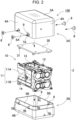
- Fig. 2 is an exploded perspective view of the battery pack of Fig. 1
- Fig. 3 is a vertical cross-sectional view of the battery pack of Fig. 1
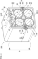
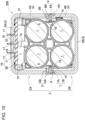
- Figs. 4 and 5 are a vertical cross-sectional perspective view and a horizontal cross-sectional perspective view of the battery pack of Fig. 1 , respectively.
- battery unit 10 formed by accommodating a plurality of secondary battery cells 1 is accommodated in exterior case 2.
- Battery unit 10 accommodates the plurality of secondary battery cells 1 inside battery holder 11 and is disposed at a fixed position.
- an outer shape of battery holder 11 is formed to be slightly smaller than an inner shape of exterior case 2 so as to be accommodated inside exterior case 2.
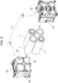
- Fig. 6 is an exploded perspective view of battery holder 11. As illustrated in Figs. 2 and 6 , battery holder 11 holds secondary battery cells 1 and substrate 30. Battery holder 11 in which secondary battery cells 1 and substrate 30 are set forms battery unit 10. Substrate 30 is placed and fixed on one surface of battery holder 11.
- Each of secondary battery cells 1 is a cylindrical secondary battery cell whose exterior can has a cylindrical shape.
- the cylindrical secondary battery cell has electrode surfaces on both end surfaces.
- a safety valve is provided on one electrode surface.
- the safety valve is a member that opens when the internal pressure of the exterior can increase and release the internal gas. Note that, although the safety valve is generally provided on the positive electrode side, the present disclosure does not specify a position where the safety valve is provided on the positive electrode side, and may be provided at another position, for example, on the negative electrode side.
- the number of secondary battery cells 1 and the stacking method are not limited to this configuration, and three or less secondary battery cells 1 or five or more secondary battery cells 1 may be held.
- the number of stages is not limited to two, and one stage, that is, all the secondary battery cells may be arranged on the same plane, or three or more stages may be stacked.
- the arrangement may be arranged in a staggered manner so as to be alternately arranged in each stage. For example, by disposing the accommodation space in two stages with the center of the cylinder of the accommodation space offset in the upper and lower stages, a thickness of the battery holder can be suppressed.
- Battery holder 11 is made of a material having excellent insulation properties and heat resistance, and is made of a resin such as polycarbonate or ABS, for example.
- an upper surface of battery holder 11 is a placement region where substrate 30 is placed.
- substrate 30 is disposed with a gap from an upper surface of battery holder 11.
- legs 31 are provided at four corner portions of substrate 30 in order to form gaps with a predetermined interval from the upper surface of battery holder 11.
- connection bosses 13 for fixing substrate 30 at fixed positions are provided on upper surfaces of sub-holders 11A, 11B.
- Substrate 30 is provided on its lower surface with connection portion 32 guided by connection boss 13, and connection portion 32 is guided by connection boss 13 and fixed at a fixed position of battery holder 11.
- a frame body for holding the substrate may be formed in an installation region of the substrate, or a substrate holder for holding the substrate may be separately provided.
- a lead plate (not illustrated) is fixed to an end surface of secondary battery cell 1.
- the plurality of secondary battery cells 1 are connected in series or in parallel via the lead plate.
- the lead plate is formed of a metal plate, and is welded to secondary battery cells 1.
- a lead positioning guide along the outer shape of the lead plate is formed on an inner surface of battery holder 11 so as to position the lead plate at a predetermined position. Note that the lead plate may be disposed not on an inner surface side but on an outer surface side of the battery holder. In this case, after the secondary battery cell is inserted into the accommodation space of the battery holder, the lead plate is fixed to the electrode surface of the secondary battery cell exposed from the battery holder.
- the output of battery unit 10 including secondary battery cells 1 connected in series or in parallel via the lead plate is output from battery pack 100.
- Electronic circuits such as a voltage detection circuit that detects a total potential or an intermediate potential of battery blocks in which secondary battery cells 1 are connected in series or in parallel, a controlling circuit that controls charging and discharging, and a safety circuit are mounted on substrate 30.
- Substrate 30 is formed in a rectangular shape.
- Exterior case 2 that accommodates battery unit 10 is formed in a rectangular parallelepiped box shape.
- exterior case 2 is divided into first case 2A and second case 2B, and battery unit 10 is accommodated so as to be sandwiched from above and below.
- a division direction of first case 2A and second case 2B intersects with a direction in which battery holder 11 is divided into sub-holders 11A, 11B by 90°, so that resistance to impact can be enhanced.
- First case 2A and second case 2B illustrated in Figs. 1 to 4 are provided with peripheral wall 4 around front surface plate 3, and have a bottomed box shape with an opening on one side as a whole.
- surface plate 3 and peripheral wall 4 are integrally formed of plastic.
- First case 2A and second case 2B in the drawings are made of a material having excellent insulation properties, for example, a resin such as polycarbonate or ABS.
- First case 2A includes first peripheral wall 4A around first surface plate 3A
- second case 2B includes second peripheral wall 4B around second surface plate 3B.
- first peripheral wall 4A and second peripheral wall 4B are connected at an open end, and battery unit 10 is accommodated inside the closed structure.
- first case 2A illustrated in Figs. 1 to 4 a large number of exhaust holes 17 are opened in first surface plate 3A, and by adjusting an amount of gas discharged from any of secondary battery cells 1 accommodated inside battery pack 100 to the outside of exterior case 2, the exhaust gas is suppressed from being jetted to the outside at once, and a situation in which flame leaks to the outside of battery pack 100 is suppressed.
- substrate 30 is disposed on an upper surface of battery unit 10 accommodated inside exterior case 2 at a position facing first surface plate 3A having a large number of exhaust holes 17 opened, limiting gap 19 for limiting a passing amount of an exhaust gas is provided between substrate 30 and first surface plate 3A, and the exhaust gas is passed through limiting gap 19 and discharged to the outside.
- limiting gap 19 between substrate 30 and front surface plate 3 to adjust the amount of the exhaust gas discharged from exhaust hole 17, the momentum of the exhaust gas discharged to the outside is suppressed, and the exhaust gas accumulated inside can be safely discharged to the outside.
- first case 2A and second case 2B illustrated in Figs. 1 to 4 stacking plates 5 stacked on the inner surface and the outer surface are connected to each other in an integral structure along the open end of each peripheral wall 4.
- the cross-sectional shapes of peripheral walls 4 of first case 2A and second case 2B are substantially rectangular, and stacking plate 5 is provided over the entire circumference of an open edge of peripheral wall 4.
- First peripheral wall 4A connects first stacking plates 5A stacked on the outer surface
- second peripheral wall 4B connects second stacking plates 5B stacked on the inner surface.
- first stacking plate 5A is provided in an attitude extending from the open end of first case 2A toward first peripheral wall 4A, and is integrally molded so as to protrude from a tip edge of first peripheral wall 4A in an extending direction of peripheral wall 4.
- First stacking plate 5A is formed to be thinner than first peripheral wall 4A, and is formed such that the outer surface of first stacking plate 5A is located on the same plane as the outer surface of first peripheral wall 4A, and the inner surface of first stacking plate 5A has a stepped shape lower than the inner surface of first peripheral wall 4A.
- second stacking plate 5B is provided in an attitude extending from the open end of second case 2B toward second peripheral wall 4B, and is integrally molded so as to protrude from a tip end surface of second peripheral wall 4B in the extending direction of peripheral wall 4.
- Second stacking plate 5B is formed to be thinner than second peripheral wall 4B, and is formed such that the inner surface of second stacking plate 5B is located on the same plane as the inner surface of second peripheral wall 4B, and the outer surface of second stacking plate 5B has a stepped shape lower than the outer surface of second peripheral wall 4B.
- first stacking plate 5A and second stacking plate 5B are connected to each other in a stacked state.
- First stacking plate 5A and second stacking plate 5B are connected to each other by stacking the outer peripheral surface of second stacking plate 5B on the inner peripheral surface of first stacking plate 5A in a surface contact state.
- first stacking plate 5A is formed to be thicker than second stacking plate 5B.
- Thickness (d1) of first stacking plate 5A is larger than 1/2 of a thickness of first peripheral wall 4A, and is 1.2 times or more, preferably 1.5 times or more thickness (d2) of second stacking plate 5B.
- first stacking plate 5A is molded to be thick has a feature that deformation of first stacking plate 5A at the time of discharging the exhaust gas can be effectively suppressed.
- thickness (d2) of second stacking plate 5B is smaller than 1/2 of a thickness of second peripheral wall 4B, and is 0.8 times or less, preferably 0.6 times or less thickness (d1) of first stacking plate 5A.
- second stacking plate 5B is reinforced by providing reinforcement mount portion 6 on the inner peripheral surface.
- reinforcement mount portion 6 protruding inward is provided on the inner peripheral surface of the open end portion of second stacking plate 5B in an integral structure.
- Reinforcement mount portion 6 reinforces second stacking plate 5B from the inside to suppress deformation, and is also used as a fixing portion for screwing screw portion 8A of fixing screw 8 for connecting a stacked portion of first stacking plate 5A and second stacking plate 5B, which will be described in detail later.
- the strength of second stacking plate 5B can be effectively enhanced by enlarging reinforcement mount portion 6.
- the size and shape of reinforcement mount portion 6 are determined in consideration of the manufacturing process and the assembly process because reinforcement mount portion 6 is restricted in the manufacturing process and the assembly process.
- protruding amount (t) of reinforcement mount portion 6 protruding inward from second stacking plate 5B of second case 2B is specified such that battery holder 11 can be easily inserted from an opening portion into second case 2B having an upper opening.
- protruding amount (t) of reinforcement mount portion 6 provided on second stacking plate 5B can be increased to the maximum within a range in which battery holder 11 can be inserted from the opening of second case 2B.
- second stacking plate 5B has a substantially rectangular cross-sectional shape, and reinforcement mount portions 6 are provided at two positions on the inner peripheral surface of second stacking plate 5B positioned on a long side of the rectangle.
- Second stacking plate 5B illustrated in Fig. 2 has a quadrangular frustum shape as a whole, and is provided at both end portions of a long side of a rectangle.
- An area of reinforcement mount portion 6 having this shape is gradually reduced in the projecting direction while increasing the bottom surface, so that excellent strength can be realized while securing a volume of the reinforcement mount portion.
- the reinforcement mount portion may have a truncated cone shape or a rectangular parallelepiped shape.
- reinforcement mount portion 6 illustrated in Fig. 8 is a projection strip extended along the open edge of second stacking plate 5B.
- Exterior case 2 including reinforcement mount portion 6 having such a shape further has a feature that deformation of second stacking plate 5B is suppressed and breakage of the stacked portion can be more effectively suppressed.
- reinforcement mount portion 6 can be provided extending from the inner surface of second stacking plate 5B to the inner surface of second peripheral wall 4B.
- the structure in which reinforcement mount portion 6 is extended to second peripheral wall 4B has a feature that the cross-sectional secondary moment in a bending direction in the cross section can be increased and the deformation in the outer direction can be further suppressed.
- reinforcement mount portion 6 can suppress the deformation of second stacking plate 5B, effectively prevent the breakage of the connection portion of exterior case 2, and effectively prevent the exhaust gas from being ejected to the outside at once.
- the second stacking plate having no reinforcement mount portion on the inner surface
- the entire second stacking plate is uniformly curved, and the deformation amount of the central portion increases.
- the reinforcement mount portion is provided on the inner surface
- the second stacking plate is provided with the reinforcement mount portion protruding inward, so that deformation of the second stacking plate as a whole is suppressed, and the breakage of this portion is suppressed.
- first stacking plate 5A and second stacking plate 5B stacked on each other is fixed via fixing screw 8.
- fixing screw 8 is screwed from the outside toward the inside in the stacked portion of first stacking plate 5A and second stacking plate 5B, and fixing screw 8 penetrating first stacking plate 5A is screwed into second stacking plate 5B, thereby connecting first stacking plate 5A and second stacking plate 5B in a state of being in close contact with each other.
- fixing screw 8 which penetrates first stacking plate 5A and is screwed into second stacking plate 5B is screwed into reinforcement mount portion 6 to be fixed thereto. That is, reinforcement mount portion 6 provided on the inner peripheral surface of second stacking plate 5B is also used as a fixing portion to which fixing screw 8 is screwed.
- a tapping screw is preferably used as fixing screw 8.
- Fixing screw 8 that is a tapping screw has a feature that fixing screw 8 can be fixed to reinforcement mount portion 6 by screwing screw portion 8A without providing a female screw hole in the fixing portion into which screw portion 8A is screwed.
- screw head 8B has a flat plate shape. By forming screw head 8B into a flat plate shape, screw head 8B can be thinned, and an amount of protrusion from the surface of exterior case 2 in a state where fixing screw 8 is screwed can be reduced.
- first stacking plate 5A and second stacking plate 5B illustrated in Fig. 7 through-holes 7 for inserting fixing screws 8 are coaxially opened at positions facing each other in the stacked portion.
- First through-hole 7A is opened in first stacking plate 5A.
- First through-hole 7A is a through-hole through which fixing screw 8 can be smoothly inserted without difficulty.
- Second through-hole 7B is opened in second stacking plate 5B.
- Second through-hole 7B is a guide hole having an inner diameter smaller than an outer diameter of screw portion 8A of fixing screw 8.
- second through-hole 7B has a structure in which fixing screw 8 can be fixed to reinforcement mount portion 6 by screwing screw portion 8A without passing screw portion 8A of fixing screw 8 with low resistance.
- Second through-hole 7B which is a guide hole, can guide a tip portion of screw portion 8A of fixing screw 8 to a fixed position and screw fixing screw 8 to an accurate position.
- screw portion 8A is screwed while smoothly guiding the tip portion of fixing screw 8, so that a rear end portion of screw portion 8A can be reliably fixed by being screwed with a large resistance.
- second through-hole 7B in Fig. 7 has a uniform inner diameter
- second through-hole 7B as a guide hole can be a tapered hole or a stepped hole, for example.
- first stacking plate 5A illustrated in Figs. 2 and 7 recess 9 for guiding screw head 8B of fixing screw 8 is provided at an open edge portion of first through-hole 7A into which fixing screw 8 is inserted.
- screw head 8B of the fixing screw 8 illustrated in the drawings has a flat plate shape
- entire recess 9 in the drawings has uniform depth (h), and depth (h) is greater than or equal to thickness (k) of screw head 8B.
- Recess 9 having this shape can prevent screw head 8B of fixing screw 8 that connects first stacking plate 5A and second stacking plate 5B from largely protruding from the outer peripheral surface of exterior case 2, and can effectively prevent the outer shape of battery pack 100 from becoming large.
- the fixing screw may slightly protrude from the surface of the exterior case.
- first peripheral wall 4A of first case 2A and second peripheral wall 4B of second case 2B have rectangular cross-sectional shapes, and stacking plate 5 is provided over the entire circumference of the open end portion of peripheral wall 4.
- stacking plates 5 located on the long side of the peripheral wall 4 having a rectangular shape in the cross section are connected and fixed by fixing screws 8.
- the structure in which stacking plates 5 located on the long sides of the first case 2A and the second case 2B having the rectangular cross-sectional shape of peripheral wall 4 are fixed by the fixing screws 8 has a feature that stacking plates 5 on the long sides that are easily deformed with respect to the short sides can be reliably connected by fixing screws 8.
- the stacking plate located on the short side of the rectangular peripheral wall can be fixed with a fixing screw.
- the stacking plates are connected with the fixing screws over the entire circumference of the peripheral wall, and the breakage of the connection portion of the exterior case can be more effectively prevented.
- a plurality of locations of stacking plate 5 located on the long side of peripheral wall 4 having a rectangular shape in the cross section are connected and fixed by fixing screws 8.
- two locations of stacking plate 5 located on the long side are fixed with fixing screws 8.
- one location or three or more locations of stacking plate 5 located on the long side can be fixed with fixing screws 8.
- first stacking plate 5A and second stacking plate 5B are connected by fixing screw 8 in a region facing valley portion 14 of battery holder 11.
Landscapes
- Chemical & Material Sciences (AREA)
- Chemical Kinetics & Catalysis (AREA)
- Electrochemistry (AREA)
- General Chemical & Material Sciences (AREA)
- Battery Mounting, Suspending (AREA)
Abstract
Description
- The present disclosure relates to a battery pack in which a chargeable/dischargeable battery is accommodated in an exterior case.
- A battery pack in which a large number of secondary battery cells are connected in series and in parallel is used as a power source for a portable electric device such as an electric cleaner or an electric power tool, or as a backup power source for a server or a power source device for home use, business use, or factory use in stationary storage applications, and is also used as a power source for driving an assist bicycle, an electric scooter, an electric cart, or a power source for driving a vehicle such as a hybrid vehicle or an electric vehicle. A lithium ion secondary battery is generally used as a secondary battery cell used in such a battery pack, but the lithium ion secondary battery may lead to an unsafe event accompanied by smoking or ignition due to some abnormality such as penetration of a bolt at the time of collision. In a case where the unsafe event occurs in the battery pack, there is a risk that ignition from the internal secondary battery cell is released to the outside of the battery pack.
- As such a battery pack, a structure in which a battery unit including a plurality of secondary battery cells is accommodated in a resin exterior case is adopted. Many exterior cases adopt a structure in which box-shaped first case and second case, each having a peripheral wall around a perimeter of a bottom plate, are connected to each other through an opening. As such an exterior case, for example, there is an exterior case using a fitting structure in which stepped portions formed to have a thin wall thickness are provided on an inner surface of an opening of one case and an outer surface of an opening of the other case, and the stepped portions are fitted to each other are stacked to form a stacked portion for connection. (See PTL 1) This structure has a feature that the first case and the second case can be accurately connected while a thickness of the stacked portion of the first case and the second case is the same as a thickness of other peripheral wall portions.
- However, in a battery pack including such an exterior case, when an abnormality such as thermal runaway occurs in the accommodated secondary battery cells and a high-temperature and high-pressure gas is released, the inside of the exterior case is filled with the gas, and as indicated by an arrow in
Fig. 12 ,flow path 94 leading fromfitting connection portion 93 ofexterior case 92 to the outside is generated, and the high-temperature and high-pressure gas is ejected from the flow path to the outside of the case, which may develop into a leakage fire accompanied by ignition. Particularly, infitting connection portion 93 of the exterior case, since stackedportions 95 are formed thin, when the high pressure gas passes through a boundary offitting connection portion 93, as indicated by a chain line inFig. 12 , outer stackedportion 95 is easily deformed outward by the gas pressure, so that a large amount of combustible gas is discharged to the outside at once and may be ignited. - Moreover, as a structure in which the box-shaped first case and second case are connected to each other through the openings, it is also possible to adopt a structure in which protrusions protruding outward are provided at facing positions of the outer peripheral surfaces of the openings of the pair of cases, an insertion portion into which a connection screw is inserted is provided in one protrusion, and a connection boss into which the connection screw penetrating the insertion portion is screwed is provided in the other protrusion. The exterior case having this structure has a feature that the protrusions provided at the facing positions of the first case and the second case are tightened with the connection screw, so that the openings can be sandwiched and firmly connected in a direction approaching each other. However, the exterior case having this structure has an adverse effect that the outer shape becomes large because the protrusions protrude on the outer peripheral surfaces. The battery pack having a large outer shape of the exterior case has a disadvantage that the battery pack cannot be disposed in a space-saving manner.
- PTL 1: Unexamined
Japanese Patent Publication No. H10-241647 - The present disclosure has been developed with the purpose of eliminating the above disadvantage, and an object of the present disclosure is to provide a battery pack capable of suppressing breakage of a connection portion of a case due to an increase in internal pressure of the battery pack caused by a gas discharged due to a battery abnormality.
- A battery pack according to an aspect of the present disclosure is a battery pack including an exterior case that accommodates a battery unit, in which the exterior case includes: a first case including a first peripheral wall around a first surface plate; and a second case including a second peripheral wall around a second surface plate, and the first case and the second case accommodate the battery unit inside a closed structure with the first peripheral wall and the second peripheral wall connected at an open end portion. The first peripheral wall and the second peripheral wall are formed by connecting stacking plates stacked on an inner surface and an outer surface to each other in an integral structure along an open end, the first peripheral wall is formed by connecting a first stacking plate stacked on the outer surface, the second peripheral wall is formed by connecting a second stacking plate stacked on the inner surface, and the second stacking plate is provided with a reinforcement mount portion protruding inward on an inner peripheral surface of the open end portion in an integral structure. The battery pack further includes a fixing screw that penetrates and connects the first stacking plate and the second stacking plate stacked on each other, and the fixing screw penetrates the first stacking plate and is screwed into the second stacking plate, and the reinforcement mount portion of the second stacking plate serves as a fixing portion to which the fixing screw is screwed.
- The battery pack of the present disclosure has a feature that it is possible to suppress the breakage of a connection portion of the case due to an increase in internal pressure of the battery pack caused by a gas discharged due to a battery abnormality.
-
-
Fig. 1 is a perspective view illustrating a battery pack according to an exemplary embodiment of the present disclosure. -
Fig. 2 is an exploded perspective view of the battery pack ofFig. 1 . -
Fig. 3 is a vertical cross-sectional view of the battery pack ofFig. 1 . -
Fig. 4 is a vertical cross-sectional perspective view of the battery pack ofFig. 1 . -
Fig. 5 is a horizontal cross-sectional perspective view of the battery pack ofFig. 1 . -
Fig. 6 is an exploded perspective view of a battery holder of a battery unit illustrated inFig. 2 . -
Fig. 7 is a cross-sectional view illustrating a state in which a fixing screw is screwed into a connection portion of a stacking plate. -
Fig. 8 is an exploded perspective view illustrating another example of an exterior case. -
Fig. 9 is an enlarged cross-sectional view illustrating a locking structure of the exterior case illustrated inFig. 8 . -
Fig. 10 is a vertical cross-sectional view illustrating another example of the battery pack. -
Fig. 11 is an enlarged cross-sectional view illustrating a state in which the stacking plates of the battery pack illustrated inFig. 10 are connected by a fixing screw. -
Fig. 12 is an enlarged cross-sectional perspective view illustrating a state in which a connection portion of an exterior case of a conventional battery pack is broken. - A battery pack according to an exemplary embodiment of the present disclosure is a battery pack including an exterior case that accommodates a battery unit, in which the exterior case includes: a first case including a first peripheral wall around a first surface plate; and a second case including a second peripheral wall around a second surface plate, and the first case and the second case accommodate the battery unit inside a closed structure with the first peripheral wall and the second peripheral wall connected at an open end portion. The first peripheral wall and the second peripheral wall are formed by connecting stacking plates stacked on an inner surface and an outer surface to each other in an integral structure along an open end, the first peripheral wall is formed by connecting a first stacking plate stacked on the outer surface, the second peripheral wall is formed by connecting a second stacking plate stacked on the inner surface, and the second stacking plate is provided with a reinforcement mount portion protruding inward on an inner peripheral surface of the open end portion in an integral structure. The battery pack further includes a fixing screw that penetrates and connects the first stacking plate and the second stacking plate stacked on each other, and the fixing screw penetrates the first stacking plate and is screwed into the second stacking plate, and the reinforcement mount portion of the second stacking plate serves as a fixing portion to which the fixing screw is screwed.
- According to the above configuration, even in a state where the internal pressure of the exterior case is increased by the gas discharged due to the battery abnormality, there is a feature that the breakage of a connection portion of the case is suppressed, and a combustible gas inside the battery pack is prevented from being released from a mating surface of the cases to the outside of the battery pack, so that the safety can be improved.
- This is because, in the above battery pack, the first case and the second case are connected by stacking the first stacking plate connected to the first peripheral wall of the first case and the second stacking plate connected to the second peripheral wall of the second case each other, the second stacking plate is reinforced by providing the reinforcement mount portion protruding inward on the inner peripheral surface of an open end portion of the second stacking plate, the first stacking plate and the second stacking plate stacked each other are connected to each other via the fixing screw, and the reinforcement mount portion of the second stacking plate serves as a fixing portion to which the fixing screw is screwed and the fixing screw penetrating the first stacking plate is screwed into the second stacking plate to fix the first stacking plate and the second stacking plate.
- In this structure, the rigidity of the second stacking plate is increased by providing the reinforcement mount portion on the inner surface of the second stacking plate stacked on the inner side, and the first stacking plate and the second stacking plate stacked each other are connected by the fixing screw while the deformation in the connection portion between the first stacking plate and the second stacking plate is suppressed, so that the first stacking plate and the second stacking plate are held in a close contact state, and an exhaust gas can be effectively prevented from leaking from the mating surface of the first stacking plate and the second stacking plate. Moreover, since the fixing screw that connects the first stacking plate and the second stacking plate is screwed with the reinforcement mount portion protruding inside the second stacking plate as the fixing portion in a state of penetrating the first stacking plate and is connected to the second stacking plate, it is possible to more firmly connect the first stacking plate and the second stacking plate by widening a meshing area with the fixing screw. That is, while the second stacking plate is reinforced by the reinforcement mount portion, the reinforcement mount portion is used as the fixing portion to which the fixing screw is screwed, and the fixing screw penetrating the first stacking plate is screwed and fixed to the reinforcement mount portion of the second stacking plate, so that it is possible to suppress the breakage of the connection portion of the case due to the increase in the internal pressure of the battery pack caused by the gas discharged due to the battery abnormality and to secure the safety. Therefore, in a state where the internal pressure of the exterior case is increased, it is possible to prevent a situation where a combustible gas in the case breaks down the connection portion between the first stacking plate and the second stacking plate and is discharged to the outside at once, and to effectively prevent the flame from leaking to the outside.
- Moreover, in the battery pack having this structure, the connection portion between the first case and the second case is connected via the fixing screw screwed to the connection portion between the first stacking plate and the second stacking plate in a penetrating direction, so that the first case and the second case can be connected without providing a connection protrusion having a shape protruding toward an outer peripheral surface side of the exterior case. Therefore, this battery package can be disposed in a space-saving manner while having a structure capable of reliably connecting the first case and the second case without increasing the outer shape of the exterior case.
- In the battery pack according to another exemplary embodiment of the present disclosure, the fixing screw may include a tapping screw. According to the above configuration, the fixing screw that is the tapping screw is screwed into the reinforcement mount portion without providing a female screw hole in the second stacking plate, whereby the second stacking plate can be easily and reliably connected.
- In the battery pack according to another exemplary embodiment of the present disclosure, the first stacking plate and the second stacking plate may coaxially open through-holes for inserting the fixing screw at positions facing each other, and the first stacking plate may be provided with a first through-hole including a through hole, and the second stacking plate may be provided with a second through-hole including a guide hole having an inner diameter smaller than an outer diameter of a threaded portion of the fixing screw.
- According to the above configuration, a tip portion of the tapping screw is smoothly guided to the second through-hole, which is the guide hole provided in the reinforcement mount portion of the second stacking plate, while the fixing screw is naturally inserted into the first through-hole, which is the through hole provided in the first stacking plate, so that the tapping screw can be easily and reliably screwed and firmly fixed along the second through-hole.
- In the battery pack according to another exemplary embodiment of the present disclosure, the first stacking plate may include a recess that guides a screw head of the fixing screw at an open edge portion of the first through-hole through which the fixing screw is inserted.
- According to the above configuration, since the recess that guides the screw head of the fixing screw is provided at the open edge portion of the first through-hole provided in the first stacking plate, it is possible to effectively prevent the screw head of the fixing screw that connects the first stacking plate and the second stacking plate from largely protruding from the outer peripheral surface of the exterior case and increasing the outer shape.
- In the battery pack according to another exemplary embodiment of the present disclosure, the screw head of the fixing screw may have a flat plate shape, and the recess provided at the open edge portion of the first through-hole has a depth (h) greater than or equal to a thickness (k) of the screw head.
- According to the above configuration, it is possible to prevent the screw head of the fixing screw guided to the recess provided in the first stacking plate from protruding from a surface of the first stacking plate, and to reliably block the outer shape of the exterior case from increasing.
- In the battery pack according to another exemplary embodiment of the present disclosure, the first stacking plate may be molded to be thicker than the second stacking plate.
- According to the above configuration, by molding the first stacking plate to be thick, deformation of the first stacking plate at the time of discharging the exhaust gas is effectively suppressed, and when the high-pressure gas passes through a boundary of the connection portion, the outer first stacking plate is prevented from being deformed outward by the gas pressure, and it is possible to effectively prevent a large amount of the exhaust gas from being discharged to the outside at once and reaching ignition.
- In the battery pack according to another exemplary embodiment of the present disclosure, the reinforcement mount portion may include a projection strip extended along an open edge of the second stacking plate.
- According to the above configuration, by forming the reinforcement mount portion provided on the inner peripheral surface of the second stacking plate into a projection strip along the open edge of the second stacking plate, the second stacking plate can be more firmly reinforced, and deformation of the second stacking plate can be suppressed.
- In the battery pack according to another exemplary embodiment of the present disclosure, the first peripheral wall of the first case and the second peripheral wall of the second case may have rectangular cross-sectional shapes, and the stacking plate may be provided over an entire circumference of an open edge portion of the peripheral wall, and the stacking plate located on a long side of the peripheral wall having a rectangular shape in a cross-sectional view may be connected by the fixing screw.
- According to the above configuration, by connecting the stacking plates located on the long sides of the first case and the second case each having a rectangular cross-sectional shape of the peripheral wall with the fixing screw, the stacking plates on the long sides which are easily deformed with respect to the short sides are reliably connected with the fixing screw, so that there is a feature that it is possible to effectively prevent the breakage of the connection portion of the exterior case.
- In the battery pack according to another exemplary embodiment of the present disclosure, the fixing screw may connect a plurality of locations of the stacking plate located on a long side of the peripheral wall having a rectangular shape in a cross-sectional view.
- In the battery pack according to another exemplary embodiment of the present disclosure, the first stacking plate and the second stacking plate connected via the fixing screw may be connected by a locking structure. The locking structure may include a locking protrusion provided to protrude from a facing surface of any one of the first stacking plate and the second stacking plate, and a locking portion provided on a facing surface of another of the first stacking plate and the second stacking plate at a position facing the locking protrusion to lock the locking protrusion.
- According to the above configuration, the first stacking plate and the second stacking plate connected via the fixing screw are connected by the locking structure, so that there is a feature that the connection portion of the first case and the second case are further firmly connected, and the breakage of the connection portion of the cases due to the increase in the internal pressure of the battery pack can be suppressed. In particular, since the locking structure includes the locking protrusion provided to protrude from the facing surface of any one of the first stacking plate and the second stacking plate, and the locking portion provided on the facing surface of the another of the first stacking plate and the second stacking plate to lock the locking protrusion, the first stacking plate and the second stacking plate are connected in a close contact state via the fixing screw, whereby a feature that the locking protrusion and the locking portion are reliably held in a locked state and the breakage of the connection portion is suppressed is realized.
- In the battery pack according to another exemplary embodiment of the present disclosure, the locking protrusion may be provided on an inner peripheral surface of the first stacking plate, the locking portion may include a locking recess provided on an outer peripheral surface of the second stacking plate, and the second stacking plate may include the reinforcement mount portion on an inner peripheral surface facing the locking recess.
- According to the above configuration, the locking protrusion is provided on the inner peripheral surface of the first stacking plate, the locking portion includes the locking recess provided on the outer peripheral surface of the second stacking plate, and the reinforcement mount portion is provided on the inner peripheral surface of the second stacking plate facing the locking recess. Therefore, the locking recess can be formed deeply to reliably lock the locking protrusion and the locking recess.
- In a battery pack according to another exemplary embodiment of the present disclosure, the battery unit may accommodate a plurality of cylindrical secondary battery cells in a battery holder, the battery holder may accommodate the plurality of secondary battery cells in a state where the secondary battery cells are stacked in a plurality of stages, and on both side surfaces, may form valley portions along an outer shape of the secondary battery cells to be stacked, and the first stacking plate and the second stacking plate may be connected by the fixing screw in a region facing the valley portions of the battery holder.
- According to the above configuration, the battery holder formed by accommodating the plurality of cylindrical secondary battery cells in the plurality of stages forms the valley portions along the outer shape of the cylindrical battery cells on both side surfaces, and the first stacking plate and the second stacking plate are connected by the fixing screw in the region facing the valley portions of the battery holder accommodated in the exterior case. Therefore, even if a tip of the fixing screw penetrating the first stacking plate and the second stacking plate enters the inside of the exterior case, the tip of the fixing screw is located in the valley portions of the battery holder and does not come into contact with the battery cells. Therefore, it is possible to realize a feature that the fixing screw can be passed through the reinforcement mount portion and reliably screwed and firmly connected without adversely affecting the secondary battery cells accommodated in the exterior case.
- In the battery pack according to another exemplary embodiment of the present disclosure, the battery holder may include a positioning plate that brings a tip of the fixing screw penetrating the first stacking plate and the second stacking plate into contact with the valley portions.
- According to the above configuration, the tip of the fixing screw screwed through the first stacking plate and the second stacking plate is brought into contact with the positioning plate provided in the valley portions of the battery holder, whereby there is a feature that the fixing screw can be held in a stable attitude.
- Hereinafter, exemplary embodiments of the present disclosure will be described with reference to the drawings. However, the exemplary embodiments described below are examples for embodying the technical idea of the present disclosure, and the present disclosure is not limited to the exemplary embodiments described below. Furthermore, in the present specification, members indicated in the claims are never specified to the members of the exemplary embodiments. In particular, the dimensions, materials, shapes, relative arrangements, and the like of the components described in the exemplary embodiments are not intended to limit the scope of the present disclosure exclusively unless otherwise specified, and are merely illustrative examples. Note that the sizes, positional relationships, or the like of members illustrated in the drawings may be exaggerated for clarity of description. Moreover, in the following description, the same names and reference marks indicate the same or similar members, and detailed description will be appropriately omitted. Moreover, the elements constituting the present disclosure may be configured such that a plurality of elements are constituted of the same member to form one member that functions as the plurality of elements, or conversely, a function of one member can be shared and achieved by a plurality of members.
- The battery pack of the present disclosure can be used as a power source for a portable electric device such as an electric cleaner or an electric power tool, or as a backup power source for a server or a power source device for home use, business use, or factory use in stationary power storage, and can also be used as a power source for driving an assist bicycle, an electric scooter, an electric cart, or a power source for driving a vehicle such as a hybrid vehicle or an electric vehicle. Hereinafter, as an exemplary embodiment of the present disclosure, a battery pack used as a power source for a portable electric device will be described.
-
Battery pack 100 according to a first exemplary embodiment of the present disclosure is illustrated inFigs. 1 to 5 .Fig. 1 is an external perspective view of a battery pack,Fig. 2 is an exploded perspective view of the battery pack ofFig. 1 ,Fig. 3 is a vertical cross-sectional view of the battery pack ofFig. 1 , andFigs. 4 and5 are a vertical cross-sectional perspective view and a horizontal cross-sectional perspective view of the battery pack ofFig. 1 , respectively. Inbattery pack 100 illustrated in these drawings,battery unit 10 formed by accommodating a plurality ofsecondary battery cells 1 is accommodated inexterior case 2. -
Battery unit 10 accommodates the plurality ofsecondary battery cells 1 insidebattery holder 11 and is disposed at a fixed position. Inbattery unit 10, an outer shape ofbattery holder 11 is formed to be slightly smaller than an inner shape ofexterior case 2 so as to be accommodated insideexterior case 2.Fig. 6 is an exploded perspective view ofbattery holder 11. As illustrated inFigs. 2 and6 ,battery holder 11 holdssecondary battery cells 1 andsubstrate 30.Battery holder 11 in whichsecondary battery cells 1 andsubstrate 30 are setforms battery unit 10.Substrate 30 is placed and fixed on one surface ofbattery holder 11. - Each of
secondary battery cells 1 is a cylindrical secondary battery cell whose exterior can has a cylindrical shape. The cylindrical secondary battery cell has electrode surfaces on both end surfaces. Furthermore, a safety valve is provided on one electrode surface. The safety valve is a member that opens when the internal pressure of the exterior can increase and release the internal gas. Note that, although the safety valve is generally provided on the positive electrode side, the present disclosure does not specify a position where the safety valve is provided on the positive electrode side, and may be provided at another position, for example, on the negative electrode side. - As such
secondary battery cell 1, a cylindrical lithium ion secondary battery can be suitably used. - However, in the battery pack of the present disclosure, the secondary battery cell is not specified as a cylindrical battery, and is not specified as a lithium ion secondary battery. As the secondary battery cell, all chargeable batteries, for example, a nickel-metal hydride battery and a nickel-cadmium battery can also be used.
-
Battery holder 11 holds the plurality ofsecondary battery cells 1.Battery holder 11 is divided into twosub-holders secondary battery cells 1 from a length direction. Each of sub-holders 11A, 11B formscylindrical accommodation space 12 for accommodating cylindricalsecondary battery cells 1. In this example, foursecondary battery cells 1 are stacked and held in an attitude of 2 rows ×2 columns.Battery holder 11 in the drawings has a structure in which the plurality of cylindricalsecondary battery cells 1 are accommodated in a state of being stacked in a plurality of stages, andvalley portions 14 having a shape conforming to the outer shape of stacked cylindricalsecondary battery cells 1 are formed on both side surfaces. - The number of
secondary battery cells 1 and the stacking method are not limited to this configuration, and three or lesssecondary battery cells 1 or five or moresecondary battery cells 1 may be held. Furthermore, the number of stages is not limited to two, and one stage, that is, all the secondary battery cells may be arranged on the same plane, or three or more stages may be stacked. Furthermore, in addition to the arrangement in a matrix form, the arrangement may be arranged in a staggered manner so as to be alternately arranged in each stage. For example, by disposing the accommodation space in two stages with the center of the cylinder of the accommodation space offset in the upper and lower stages, a thickness of the battery holder can be suppressed.Battery holder 11 is made of a material having excellent insulation properties and heat resistance, and is made of a resin such as polycarbonate or ABS, for example. - Moreover, an upper surface of
battery holder 11 is a placement region wheresubstrate 30 is placed. Inbattery unit 10 illustrated inFig. 3 ,substrate 30 is disposed with a gap from an upper surface ofbattery holder 11. Insubstrate 30 ofFig. 2 ,legs 31 are provided at four corner portions ofsubstrate 30 in order to form gaps with a predetermined interval from the upper surface ofbattery holder 11. Moreover, inbattery holder 11,connection bosses 13 for fixingsubstrate 30 at fixed positions are provided on upper surfaces of sub-holders 11A, 11B. -
Substrate 30 is provided on its lower surface withconnection portion 32 guided byconnection boss 13, andconnection portion 32 is guided byconnection boss 13 and fixed at a fixed position ofbattery holder 11. However, in the battery unit, a frame body for holding the substrate may be formed in an installation region of the substrate, or a substrate holder for holding the substrate may be separately provided. - A lead plate (not illustrated) is fixed to an end surface of
secondary battery cell 1. The plurality ofsecondary battery cells 1 are connected in series or in parallel via the lead plate. The lead plate is formed of a metal plate, and is welded tosecondary battery cells 1. A lead positioning guide along the outer shape of the lead plate is formed on an inner surface ofbattery holder 11 so as to position the lead plate at a predetermined position. Note that the lead plate may be disposed not on an inner surface side but on an outer surface side of the battery holder. In this case, after the secondary battery cell is inserted into the accommodation space of the battery holder, the lead plate is fixed to the electrode surface of the secondary battery cell exposed from the battery holder. The output ofbattery unit 10 includingsecondary battery cells 1 connected in series or in parallel via the lead plate is output frombattery pack 100. - Electronic circuits such as a voltage detection circuit that detects a total potential or an intermediate potential of battery blocks in which
secondary battery cells 1 are connected in series or in parallel, a controlling circuit that controls charging and discharging, and a safety circuit are mounted onsubstrate 30.Substrate 30 is formed in a rectangular shape. -
Exterior case 2 that accommodatesbattery unit 10 is formed in a rectangular parallelepiped box shape. In the examples ofFigs. 1 to 5 ,exterior case 2 is divided intofirst case 2A andsecond case 2B, andbattery unit 10 is accommodated so as to be sandwiched from above and below. A division direction offirst case 2A andsecond case 2B intersects with a direction in whichbattery holder 11 is divided into sub-holders 11A, 11B by 90°, so that resistance to impact can be enhanced. -
First case 2A andsecond case 2B illustrated inFigs. 1 to 4 are provided withperipheral wall 4 aroundfront surface plate 3, and have a bottomed box shape with an opening on one side as a whole. Infirst case 2A andsecond case 2B,surface plate 3 andperipheral wall 4 are integrally formed of plastic.First case 2A andsecond case 2B in the drawings are made of a material having excellent insulation properties, for example, a resin such as polycarbonate or ABS.First case 2A includes firstperipheral wall 4A aroundfirst surface plate 3A, andsecond case 2B includes secondperipheral wall 4B aroundsecond surface plate 3B. Infirst case 2A andsecond case 2B, firstperipheral wall 4A and secondperipheral wall 4B are connected at an open end, andbattery unit 10 is accommodated inside the closed structure. - Moreover, in
first case 2A illustrated inFigs. 1 to 4 , a large number of exhaust holes 17 are opened infirst surface plate 3A, and by adjusting an amount of gas discharged from any ofsecondary battery cells 1 accommodated insidebattery pack 100 to the outside ofexterior case 2, the exhaust gas is suppressed from being jetted to the outside at once, and a situation in which flame leaks to the outside ofbattery pack 100 is suppressed. Inbattery pack 100 illustrated inFig. 3 ,substrate 30 is disposed on an upper surface ofbattery unit 10 accommodated insideexterior case 2 at a position facingfirst surface plate 3A having a large number of exhaust holes 17 opened, limitinggap 19 for limiting a passing amount of an exhaust gas is provided betweensubstrate 30 andfirst surface plate 3A, and the exhaust gas is passed through limitinggap 19 and discharged to the outside. In this manner, by providing limitinggap 19 betweensubstrate 30 andfront surface plate 3 to adjust the amount of the exhaust gas discharged fromexhaust hole 17, the momentum of the exhaust gas discharged to the outside is suppressed, and the exhaust gas accumulated inside can be safely discharged to the outside. - As indicated by a chain line in the drawing, a large number of exhaust holes 17 opened in
first surface plate 3A are closed by attachinglabel 18 melted by heat of the discharged gas. - In
first case 2A andsecond case 2B illustrated inFigs. 1 to 4 , stackingplates 5 stacked on the inner surface and the outer surface are connected to each other in an integral structure along the open end of eachperipheral wall 4. Inexterior case 2 in the drawings, the cross-sectional shapes ofperipheral walls 4 offirst case 2A andsecond case 2B are substantially rectangular, and stackingplate 5 is provided over the entire circumference of an open edge ofperipheral wall 4. Firstperipheral wall 4A connects first stackingplates 5A stacked on the outer surface, and secondperipheral wall 4B connects second stackingplates 5B stacked on the inner surface. - As illustrated in
Figs. 3 and4 , first stackingplate 5A is provided in an attitude extending from the open end offirst case 2A toward firstperipheral wall 4A, and is integrally molded so as to protrude from a tip edge of firstperipheral wall 4A in an extending direction ofperipheral wall 4. First stackingplate 5A is formed to be thinner than firstperipheral wall 4A, and is formed such that the outer surface of first stackingplate 5A is located on the same plane as the outer surface of firstperipheral wall 4A, and the inner surface of first stackingplate 5A has a stepped shape lower than the inner surface of firstperipheral wall 4A. - As illustrated in
Figs. 2 to 4 , second stackingplate 5B is provided in an attitude extending from the open end ofsecond case 2B toward secondperipheral wall 4B, and is integrally molded so as to protrude from a tip end surface of secondperipheral wall 4B in the extending direction ofperipheral wall 4. Second stackingplate 5B is formed to be thinner than secondperipheral wall 4B, and is formed such that the inner surface of second stackingplate 5B is located on the same plane as the inner surface of secondperipheral wall 4B, and the outer surface of second stackingplate 5B has a stepped shape lower than the outer surface of secondperipheral wall 4B. - As illustrated in
Figs. 3 to 5 , first stackingplate 5A and second stackingplate 5B are connected to each other in a stacked state. First stackingplate 5A and second stackingplate 5B are connected to each other by stacking the outer peripheral surface of second stackingplate 5B on the inner peripheral surface of first stackingplate 5A in a surface contact state. Inexterior case 2 illustrated inFigs. 3 to 5 and7 , first stackingplate 5A is formed to be thicker than second stackingplate 5B. Thickness (d1) of first stackingplate 5A is larger than 1/2 of a thickness of firstperipheral wall 4A, and is 1.2 times or more, preferably 1.5 times or more thickness (d2) of second stackingplate 5B. As described above,exterior case 2 in which first stackingplate 5A is molded to be thick has a feature that deformation of first stackingplate 5A at the time of discharging the exhaust gas can be effectively suppressed. In particular, when the high-pressure exhaust gas passes through a boundary between the connection portions of first stackingplate 5A and second stackingplate 5B, it is possible to effectively prevent first stackingplate 5A from being deformed outward by the gas pressure. On the other hand, thickness (d2) of second stackingplate 5B is smaller than 1/2 of a thickness of secondperipheral wall 4B, and is 0.8 times or less, preferably 0.6 times or less thickness (d1) of first stackingplate 5A. As described above, the structure in which second stackingplate 5B is thinly molded is easily deformed at the time of discharging the exhaust gas, but second stackingplate 5B is reinforced by providingreinforcement mount portion 6 on the inner peripheral surface. - In second
peripheral wall 4B,reinforcement mount portion 6 protruding inward is provided on the inner peripheral surface of the open end portion of second stackingplate 5B in an integral structure.Reinforcement mount portion 6 reinforces second stackingplate 5B from the inside to suppress deformation, and is also used as a fixing portion for screwingscrew portion 8A of fixingscrew 8 for connecting a stacked portion of first stackingplate 5A and second stackingplate 5B, which will be described in detail later. The strength of second stackingplate 5B can be effectively enhanced by enlargingreinforcement mount portion 6. However, when the size ofreinforcement mount portion 6 is increased, the size and shape ofreinforcement mount portion 6 are determined in consideration of the manufacturing process and the assembly process becausereinforcement mount portion 6 is restricted in the manufacturing process and the assembly process. For example, as illustrated inFig. 2 , protruding amount (t) ofreinforcement mount portion 6 protruding inward from second stackingplate 5B ofsecond case 2B is specified such thatbattery holder 11 can be easily inserted from an opening portion intosecond case 2B having an upper opening. In other words, protruding amount (t) ofreinforcement mount portion 6 provided on second stackingplate 5B can be increased to the maximum within a range in whichbattery holder 11 can be inserted from the opening ofsecond case 2B. - In
exterior case 2 illustrated inFig. 2 , second stackingplate 5B has a substantially rectangular cross-sectional shape, andreinforcement mount portions 6 are provided at two positions on the inner peripheral surface of second stackingplate 5B positioned on a long side of the rectangle. Second stackingplate 5B illustrated inFig. 2 has a quadrangular frustum shape as a whole, and is provided at both end portions of a long side of a rectangle. An area ofreinforcement mount portion 6 having this shape is gradually reduced in the projecting direction while increasing the bottom surface, so that excellent strength can be realized while securing a volume of the reinforcement mount portion. However, the reinforcement mount portion may have a truncated cone shape or a rectangular parallelepiped shape. It is also possible to have a shape obtained by partially cutting a cylinder or a sphere. In the exterior case illustrated inFig. 2 , tworeinforcement mount portions 6 are provided for second stackingplate 5B on one side, but onereinforcement mount portion 6 may be provided for second stackingplate 5B on one side, or three or morereinforcement mount portions 6 may be provided for second stackingplate 5B on one side.Reinforcement mount portion 6 illustrated inFig. 8 is a projection strip extended along the open edge of second stackingplate 5B.Exterior case 2 includingreinforcement mount portion 6 having such a shape further has a feature that deformation of second stackingplate 5B is suppressed and breakage of the stacked portion can be more effectively suppressed. - Moreover, as indicated by a chain line in
Fig. 3 ,reinforcement mount portion 6 can be provided extending from the inner surface of second stackingplate 5B to the inner surface of secondperipheral wall 4B. As described above, the structure in whichreinforcement mount portion 6 is extended to secondperipheral wall 4B has a feature that the cross-sectional secondary moment in a bending direction in the cross section can be increased and the deformation in the outer direction can be further suppressed. Therefore, even when the gas is discharged from any ofsecondary battery cells 1 accommodated insideexterior case 2 and a force that deforms second stackingplate 5B from the inside to the outside acts,reinforcement mount portion 6 can suppress the deformation of second stackingplate 5B, effectively prevent the breakage of the connection portion ofexterior case 2, and effectively prevent the exhaust gas from being ejected to the outside at once. - Here, in the second stacking plate having no reinforcement mount portion on the inner surface, when the pressure inside the exterior case increases, the entire second stacking plate is uniformly curved, and the deformation amount of the central portion increases. On the other hand, in the second stacking plate in which the reinforcement mount portion is provided on the inner surface, even when the internal pressure of the exterior case increases, the deformation of a region where the reinforcement mount portion is provided is partially suppressed, so that the deformation of the entire second stacking plate is suppressed without uniformly curving the entire second stacking plate, and the deformation amount of the central portion decreases. Therefore, the second stacking plate is provided with the reinforcement mount portion protruding inward, so that deformation of the second stacking plate as a whole is suppressed, and the breakage of this portion is suppressed.
- Moreover, in
exterior case 2 illustrated inFigs. 1 to 5 and7 , a stacked portion of first stackingplate 5A and second stackingplate 5B stacked on each other is fixed via fixingscrew 8. Inexterior case 2 illustrated in the drawings, fixingscrew 8 is screwed from the outside toward the inside in the stacked portion of first stackingplate 5A and second stackingplate 5B, and fixingscrew 8 penetrating first stackingplate 5A is screwed into second stackingplate 5B, thereby connecting first stackingplate 5A and second stackingplate 5B in a state of being in close contact with each other. Moreover, inexterior case 2 illustrated in the drawings, fixingscrew 8 which penetrates first stackingplate 5A and is screwed into second stackingplate 5B is screwed intoreinforcement mount portion 6 to be fixed thereto. That is,reinforcement mount portion 6 provided on the inner peripheral surface of second stackingplate 5B is also used as a fixing portion to which fixingscrew 8 is screwed. - A tapping screw is preferably used as fixing
screw 8. Fixingscrew 8 that is a tapping screw has a feature that fixingscrew 8 can be fixed toreinforcement mount portion 6 by screwingscrew portion 8A without providing a female screw hole in the fixing portion into whichscrew portion 8A is screwed. Moreover, in fixingscrew 8 illustrated in the drawings,screw head 8B has a flat plate shape. By formingscrew head 8B into a flat plate shape,screw head 8B can be thinned, and an amount of protrusion from the surface ofexterior case 2 in a state where fixingscrew 8 is screwed can be reduced. - In first stacking
plate 5A and second stackingplate 5B illustrated inFig. 7 , through-holes 7 for inserting fixingscrews 8 are coaxially opened at positions facing each other in the stacked portion. First through-hole 7A is opened in first stackingplate 5A. First through-hole 7A is a through-hole through which fixingscrew 8 can be smoothly inserted without difficulty. Second through-hole 7B is opened in second stackingplate 5B. Second through-hole 7B is a guide hole having an inner diameter smaller than an outer diameter ofscrew portion 8A of fixingscrew 8. For example, second through-hole 7B has a structure in which fixingscrew 8 can be fixed toreinforcement mount portion 6 by screwingscrew portion 8A without passingscrew portion 8A of fixingscrew 8 with low resistance. Second through-hole 7B, which is a guide hole, can guide a tip portion ofscrew portion 8A of fixingscrew 8 to a fixed position andscrew fixing screw 8 to an accurate position. In second through-hole 7B illustrated inFig. 7 ,screw portion 8A is screwed while smoothly guiding the tip portion of fixingscrew 8, so that a rear end portion ofscrew portion 8A can be reliably fixed by being screwed with a large resistance. Although second through-hole 7B inFig. 7 has a uniform inner diameter, second through-hole 7B as a guide hole can be a tapered hole or a stepped hole, for example. - Moreover, in first stacking
plate 5A illustrated inFigs. 2 and7 ,recess 9 for guidingscrew head 8B of fixingscrew 8 is provided at an open edge portion of first through-hole 7A into which fixingscrew 8 is inserted. Sincescrew head 8B of the fixingscrew 8 illustrated in the drawings has a flat plate shape,entire recess 9 in the drawings has uniform depth (h), and depth (h) is greater than or equal to thickness (k) ofscrew head 8B.Recess 9 having this shape can preventscrew head 8B of fixingscrew 8 that connects first stackingplate 5A and second stackingplate 5B from largely protruding from the outer peripheral surface ofexterior case 2, and can effectively prevent the outer shape ofbattery pack 100 from becoming large. However, the fixing screw may slightly protrude from the surface of the exterior case. - As illustrated in
Figs. 2 and5 , inexterior case 2 described above, firstperipheral wall 4A offirst case 2A and secondperipheral wall 4B ofsecond case 2B have rectangular cross-sectional shapes, and stackingplate 5 is provided over the entire circumference of the open end portion ofperipheral wall 4. Moreover, stackingplates 5 located on the long side of theperipheral wall 4 having a rectangular shape in the cross section are connected and fixed by fixingscrews 8. As described above, the structure in which stackingplates 5 located on the long sides of thefirst case 2A and thesecond case 2B having the rectangular cross-sectional shape ofperipheral wall 4 are fixed by the fixing screws 8 has a feature that stackingplates 5 on the long sides that are easily deformed with respect to the short sides can be reliably connected by fixingscrews 8. However, in the exterior case, the stacking plate located on the short side of the rectangular peripheral wall can be fixed with a fixing screw. In this structure, the stacking plates are connected with the fixing screws over the entire circumference of the peripheral wall, and the breakage of the connection portion of the exterior case can be more effectively prevented. - Moreover, in the battery pack described above, a plurality of locations of stacking
plate 5 located on the long side ofperipheral wall 4 having a rectangular shape in the cross section are connected and fixed by fixingscrews 8. Inbattery pack 100 illustrated in the drawings, two locations of stackingplate 5 located on the long side are fixed with fixingscrews 8. However, in the battery pack, one location or three or more locations of stackingplate 5 located on the long side can be fixed with fixingscrews 8. - Moreover, in
battery pack 100 in which stackingplates 5 located on the long side are connected by fixingscrews 8, as illustrated inFig. 3 , fixingscrews 8 connecting stackingplates 5 are located to facevalley portions 14 ofbattery holder 11 accommodated inexterior case 2. Inbattery unit 10 illustrated inFigs. 2 and6 , the plurality of cylindricalsecondary battery cells 1 are accommodated inbattery holder 11, andbattery holder 11 accommodates the plurality ofsecondary battery cells 1 in a state wheresecondary battery cells 1 are stacked in a plurality of stages, andvalley portions 14 along the outer shape of stackedsecondary battery cells 1 are formed on both side surfaces. Inbattery pack 100, first stackingplate 5A and second stackingplate 5B are connected by fixingscrew 8 in a region facingvalley portion 14 ofbattery holder 11. Therefore, even if the tip of fixingscrew 8 penetrating first stackingplate 5A and second stackingplate 5B enters the inside ofexterior case 2, the tip of fixingscrew 8 is located invalley portion 14 ofbattery holder 11, so that the tip does not come into contact withsecondary battery cell 1. Therefore, without adversely affectingsecondary battery cells 1 accommodated inexterior case 2, fixingscrews 8 can be passed throughreinforcement mount portion 6 and reliably screwed, andsecondary battery cells 1 can be firmly connected. - Moreover, in
battery pack 100, first stackingplate 5A and second stackingplate 5B connected via fixingscrew 8 can be connected by a locking structure. The locking structure may be, for example, a locking protrusion provided so as to protrude from a facing surface of any one of first stackingplate 5A and second stackingplate 5B, and a locking portion provided on a facing surface of the other of first stackingplate 5A and second stackingplate 5B at a position facing the locking protrusion to lock the locking protrusion. The locking portion may be a locking recess or a locking hole capable of locking the locking protrusion. -
Figs. 8 and9 illustrate an example in which first stackingplate 5A and second stackingplate 5B are connected by lockingstructure 20. Lockingstructure 20 illustrated in the drawings includes lockingprotrusion 21 provided on the inner peripheral surface of first stackingplate 5A and lockingrecess 22 provided on the outer peripheral surface of second stackingplate 5B. In lockingstructure 20, lockingprotrusion 21 provided on first stackingplate 5A is formed into a hook shape, and lockingrecess 22 provided on second stackingplate 5B is formed into a recess having a rectangular cross-sectional view capable of guiding hook-shapedlocking protrusion 21 in a locked state. Moreover, lockingstructure 20 illustrated inFig. 8 is provided on stackingplate 5 located on the long side and connected via fixingscrew 8. As described above, in the structure in which stackingplates 5 connected by fixingscrews 8 are locked by lockingstructure 20, first stackingplate 5A and second stackingplate 5B are connected in a close contact state via fixingscrews 8, so that a feature that lockingprotrusion 21 and lockingrecess 22 are reliably held in the locked state is realized. - Moreover, in second stacking
plate 5B illustrated inFigs. 8 and9 ,reinforcement mount portion 6 is provided on the inner peripheral surface facing lockingrecess 22 provided in second stackingplate 5B.Reinforcement mount portion 6 illustrated inFig. 8 also serves as a fixing portion for screwing fixingscrew 8 as a projection strip extended along the open edge of second stackingplate 5B, butreinforcement mount portion 6 may be provided at a position facing lockingrecess 22 to reinforce the locking recess. As described above, the structure in whichreinforcement mount portion 6 is provided opposite to the position where lockingrecess 22 is provided has a feature that lockingrecess 22 can be formed deeply, so that a protruding amount of lockingprotrusion 21 can be increased, and lockingprotrusion 21 can be more reliably locked to lockingrecess 22 and hardly detached. For example, second stackingplate 5B formed thinner than secondperipheral wall 4B is restricted in the depth of lockingrecess 22 by the thickness of second stackingplate 5B, but the locking recess can be provided at an ideal depth by providingreinforcement mount portion 6 at the position of lockingrecess 22. - Moreover, the battery pack may have a structure illustrated in
Figs. 10 and11 . Inbattery pack 200 illustrated in these drawings,valley portion 14 ofbattery holder 11 is provided withpositioning plate 16 that brings the tip of fixingscrew 8 penetrating first stackingplate 5A and second stackingplate 5B into contact with each other. Positioningplate 16 illustrated in the drawings is provided at a position where the tip of fixingscrew 8 screwed through first stackingplate 5A and second stackingplate 5B abuts or comes into contact in a pressed state. Although positioningplate 16 illustrated in the drawings is a part ofbattery holder 11,positioning plate 16 may be disposed as a separate member from the battery holder. - As described above, the tip of fixing
screw 8 screwed into stackingplate 5 comes into contact withpositioning plate 16, so that there is a feature that the attitude of fixingscrew 8 can be correctly held. As illustrated inFig. 11 , when the pressure insideexterior case 2 increases, firstperipheral wall 4A is pulled in a direction indicated by arrow A, and secondperipheral wall 4B is pulled in a direction indicated by arrow B due to the reaction,screw portion 8A of fixingscrew 8 is in a state whererear end portion 8a is pulled in the direction indicated by the arrow A, andintermediate portion 8b is pulled in the direction indicated by arrow B. At this time,screw portion 8A of fixingscrew 8 receives a force in a direction inclined from the horizontal attitude. However, as illustrated inFig. 11 ,tip portion 8c ofscrew portion 8A comes into contact withpositioning plate 16, so that the force is received in a direction indicated by arrow C in the drawing, and the inclination ofscrew portion 8A is suppressed. Therefore,screw portion 8A can be held in a stable attitude by providingpositioning plate 16 with whichtip portion 8c of fixingscrew 8 comes into contact. - The battery pack according to the present disclosure can be suitably used as a power source of a portable electric device such as an electric cleaner or an electric tool. Furthermore, the present disclosure can be appropriately used for applications such as a power source device for a moving body such as an assist bicycle and an electric cart.
-
- 100, 200: battery pack
- 1: secondary battery cell
- 2: exterior case
- 2A: first case
- 2B: second case
- 3: surface plate
- 3A: first surface plate
- 3B: first surface plate
- 4: peripheral wall
- 4A: first peripheral wall
- 4B: second peripheral wall
- 5: stacking plate
- 5A: first stacking plate
- 5B: second stacking plate
- 6: reinforcement mount portion
- 7: through-hole
- 7A: first through-hole
- 7B: second through-hole
- 8: fixing screw
- 8A: screw portion
- 8a: rear end portion
- 8b: intermediate portion
- 8c: tip portion
- 8B: screw head
- 9: recess
- 10: battery unit
- 11: battery holder
- 11A, 11B: sub-holder
- 12: accommodation space
- 13: connection boss
- 14: valley portion
- 16: positioning plate
- 17: exhaust hole
- 18: label
- 19: limiting gap
- 20: locking structure
- 21: locking protrusion
- 22: locking recess
- 30: substrate
- 31: leg
- 32: connection portion
- 92: exterior case
- 93: fitting connection portion
- 94: flow path
- 95: stacked portion
Claims (13)
- A battery pack comprising an exterior case that accommodates a battery unit,wherein the exterior case includesa first case including a first peripheral wall around a first surface plate, anda second case including a second peripheral wall around a second surface plate,the first case and the second case form a closed structure by being connected with each other at open end portions of the first and second peripheral walls, and accommodate the battery unit inside the closed structure,the first peripheral wall and the second peripheral wall are formed by connecting stacking plates stacked on an inner surface and an outer surface to each other in an integral structure along an open end,the first peripheral wall is formed by connecting a first stacking plate stacked on the outer surface,the second peripheral wall is formed by connecting a second stacking plate stacked on the inner surface,the second stacking plate is provided with a reinforcement mount portion protruding inward on an inner peripheral surface of the open end portion in an integral structure,the battery pack further includes a fixing screw that penetrates and connects the first stacking plate and the second stacking plate stacked on each other, andthe fixing screw penetrates the first stacking plate and is screwed into the second stacking plate, and the reinforcement mount portion of the second stacking plate serves as a fixing portion to which the fixing screw is screwed.
- The battery pack according to Claim 1, wherein the fixing screw includes a tapping screw.
- The battery pack according to Claim 2, whereinthe first stacking plate and the second stacking plate coaxially open through-holes for inserting the fixing screw at positions facing each other, andthe first stacking plate is provided with a first through-hole including a through hole, and the second stacking plate is provided with a second through-hole including a guide hole having an inner diameter smaller than an outer diameter of a threaded portion of the fixing screw.
- The battery pack according to Claim 3, wherein the first stacking plate includes a recess that guides a screw head of the fixing screw at an open edge portion of the first through-hole through which the fixing screw is inserted.
- The battery pack according to Claim 4, wherein the screw head of the fixing screw has a flat plate shape, and the recess provided at the open edge portion of the first through-hole has a depth (h) greater than or equal to a thickness (k) of the screw head.
- The battery pack according to any one of Claims 1 to 5, wherein the first stacking plate is formed to be thicker than the second stacking plate.
- The battery pack according to any one of Claims 1 to 6, wherein the reinforcement mount portion includes a projection strip extended along an open edge of the second stacking plate.
- The battery pack according to any one of Claims 1 to 7, whereinthe first peripheral wall of the first case and the second peripheral wall of the second case have rectangular cross-sectional shapes, and at least one of the stacking plates is provided over an entire circumference of an open edge portion of at least one of the first and second peripheral walls, andthe at least one of the stacking plates located on a long side of the at least one of the first and second peripheral walls having a rectangular shape in a cross-sectional view is connected by the fixing screw.
- The battery pack according to Claim 8, wherein a plurality of the fixing screws connect a plurality of locations of the at least one of the stacking plates located on the long side of the at least one of the first and second peripheral walls having the rectangular shape in the cross-sectional view.
- The battery pack according to any one of Claims 1 to 9, whereinthe first stacking plate and the second stacking plate connected via the fixing screw are connected by a locking structure, andthe locking structure includesa locking protrusion provided to protrude from a facing surface of any one of the first stacking plate and the second stacking plate, anda locking portion provided on a facing surface of another of the first stacking plate and the second stacking plate at a position facing the locking protrusion to lock the locking protrusion.
- The battery pack according to Claim 10, whereinthe locking protrusion is provided on an inner peripheral surface of the first stacking plate,the locking portion includes a locking recess provided on an outer peripheral surface of the second stacking plate, andthe second stacking plate includes the reinforcement mount portion on an inner peripheral surface facing the locking recess.
- The battery pack according to any one of Claims 1 to 11, whereinthe battery unit accommodates a plurality of cylindrical secondary battery cells in a battery holder,the battery holder accommodates the plurality of secondary battery cells in a state where the secondary battery cells are stacked in a plurality of stages, and on both side surfaces, forms valley portions along an outer shape of the secondary battery cells to be stacked, andthe first stacking plate and the second stacking plate are connected by the fixing screw in a region facing the valley portions of the battery holder.
- The battery pack according to Claim 12, wherein the battery holder includes a positioning plate that brings a tip of the fixing screw penetrating the first stacking plate and the second stacking plate into contact with the valley portions.
Applications Claiming Priority (2)
| Application Number | Priority Date | Filing Date | Title |
|---|---|---|---|
| JP2022054240 | 2022-03-29 | ||
| PCT/JP2023/005584 WO2023188958A1 (en) | 2022-03-29 | 2023-02-16 | Battery pack |
Publications (2)
| Publication Number | Publication Date |
|---|---|
| EP4503281A1 true EP4503281A1 (en) | 2025-02-05 |
| EP4503281A4 EP4503281A4 (en) | 2025-07-16 |
Family
ID=88200275
Family Applications (1)
| Application Number | Title | Priority Date | Filing Date |
|---|---|---|---|
| EP23778988.8A Pending EP4503281A4 (en) | 2022-03-29 | 2023-02-16 | BATTERY PACK |
Country Status (5)
| Country | Link |
|---|---|
| US (1) | US20250201998A1 (en) |
| EP (1) | EP4503281A4 (en) |
| JP (1) | JPWO2023188958A1 (en) |
| CN (1) | CN118922989A (en) |
| WO (1) | WO2023188958A1 (en) |
Family Cites Families (8)
| Publication number | Priority date | Publication date | Assignee | Title |
|---|---|---|---|---|
| JP3777703B2 (en) | 1997-02-27 | 2006-05-24 | 株式会社ジーエス・ユアサコーポレーション | Battery pack and manufacturing method thereof |
| JP6702554B2 (en) * | 2016-10-04 | 2020-06-03 | 株式会社東芝 | Explosion-proof waterproof case |
| US11923555B2 (en) * | 2018-04-25 | 2024-03-05 | Panasonic Energy Co., Ltd. | Battery pack |
| EP3823059B1 (en) * | 2018-07-11 | 2024-07-31 | Panasonic Energy Co., Ltd. | Battery pack |
| JP7292310B2 (en) * | 2018-12-21 | 2023-06-16 | パナソニックエナジー株式会社 | pack batteries |
| CN212542576U (en) * | 2020-03-31 | 2021-02-12 | 自贡迅安达科技有限公司 | Swing car power battery with waterproof function |
| US20240234937A9 (en) * | 2021-02-25 | 2024-07-11 | Panasonic Energy Co., Ltd. | Battery pack |
| CN214898719U (en) * | 2021-04-30 | 2021-11-26 | 郑州锐晶裕华新能源有限公司 | Portable waterproof passenger train tail battery |
-
2023
- 2023-02-16 WO PCT/JP2023/005584 patent/WO2023188958A1/en not_active Ceased
- 2023-02-16 JP JP2024511410A patent/JPWO2023188958A1/ja active Pending
- 2023-02-16 US US18/849,753 patent/US20250201998A1/en active Pending
- 2023-02-16 CN CN202380030491.1A patent/CN118922989A/en active Pending
- 2023-02-16 EP EP23778988.8A patent/EP4503281A4/en active Pending
Also Published As
| Publication number | Publication date |
|---|---|
| WO2023188958A1 (en) | 2023-10-05 |
| US20250201998A1 (en) | 2025-06-19 |
| EP4503281A4 (en) | 2025-07-16 |
| JPWO2023188958A1 (en) | 2023-10-05 |
| CN118922989A (en) | 2024-11-08 |
Similar Documents
| Publication | Publication Date | Title |
|---|---|---|
| EP3916866B1 (en) | Battery pack | |
| US20240313339A1 (en) | Battery cell, battery and electricity-consuming apparatus | |
| US10658635B2 (en) | Battery pack and vehicle equipped with same | |
| US8808907B2 (en) | Battery module | |
| US20160322613A1 (en) | Battery pack | |
| KR20220129323A (en) | Battery module and battery pack including same | |
| US20250286226A1 (en) | Battery cell, battery, and electrical device | |
| EP4235932A2 (en) | Battery pack | |
| KR20240086512A (en) | Battery cell, and battery pack and vehicle including same | |
| EP4300681A1 (en) | Battery pack | |
| JP7815443B2 (en) | Battery pack and vehicle including same | |
| US20250201998A1 (en) | Battery pack | |
| KR20240102774A (en) | Battery module, and battery pack and vehicle including same | |
| EP4175043A1 (en) | Battery module and battery pack comprising same | |
| KR20050121903A (en) | Secondary battery and cap assembly and safety valve using the same and method for mounting safety valve | |
| US20250253499A1 (en) | Battery | |
| WO2020026966A1 (en) | Cell module fixing structure | |
| US20250062495A1 (en) | Battery cell, battery, and electric device | |
| EP4471950A1 (en) | Battery pack | |
| EP4498496A1 (en) | Battery pack | |
| EP4235931A2 (en) | Battery pack | |
| CN221508352U (en) | Insert structure, battery and power device | |
| KR20240030988A (en) | Battery pack and vehicle including same | |
| EP4700958A1 (en) | Battery pack and vehicle including same | |
| KR20220018743A (en) | Battery Cell With Edge Cover |
Legal Events
| Date | Code | Title | Description |
|---|---|---|---|
| STAA | Information on the status of an ep patent application or granted ep patent |
Free format text: STATUS: THE INTERNATIONAL PUBLICATION HAS BEEN MADE |
|
| PUAI | Public reference made under article 153(3) epc to a published international application that has entered the european phase |
Free format text: ORIGINAL CODE: 0009012 |
|
| STAA | Information on the status of an ep patent application or granted ep patent |
Free format text: STATUS: REQUEST FOR EXAMINATION WAS MADE |
|
| 17P | Request for examination filed |
Effective date: 20241015 |
|
| AK | Designated contracting states |
Kind code of ref document: A1 Designated state(s): AL AT BE BG CH CY CZ DE DK EE ES FI FR GB GR HR HU IE IS IT LI LT LU LV MC ME MK MT NL NO PL PT RO RS SE SI SK SM TR |
|
| DAV | Request for validation of the european patent (deleted) | ||
| DAX | Request for extension of the european patent (deleted) | ||
| A4 | Supplementary search report drawn up and despatched |
Effective date: 20250618 |
|
| RIC1 | Information provided on ipc code assigned before grant |
Ipc: H01M 50/204 20210101AFI20250612BHEP Ipc: H01M 50/244 20210101ALI20250612BHEP Ipc: H01M 50/262 20210101ALI20250612BHEP Ipc: H01M 50/271 20210101ALI20250612BHEP Ipc: H01M 50/233 20210101ALI20250612BHEP Ipc: H01M 50/213 20210101ALN20250612BHEP |