EP4503277A1 - End cap assembly, battery cell, battery and electric device - Google Patents
End cap assembly, battery cell, battery and electric device Download PDFInfo
- Publication number
- EP4503277A1 EP4503277A1 EP22957735.8A EP22957735A EP4503277A1 EP 4503277 A1 EP4503277 A1 EP 4503277A1 EP 22957735 A EP22957735 A EP 22957735A EP 4503277 A1 EP4503277 A1 EP 4503277A1
- Authority
- EP
- European Patent Office
- Prior art keywords
- cover plate
- insulating member
- rotation
- rotation portion
- groove
- Prior art date
- Legal status (The legal status is an assumption and is not a legal conclusion. Google has not performed a legal analysis and makes no representation as to the accuracy of the status listed.)
- Pending
Links
Images




Classifications
-
- H—ELECTRICITY
- H01—ELECTRIC ELEMENTS
- H01M—PROCESSES OR MEANS, e.g. BATTERIES, FOR THE DIRECT CONVERSION OF CHEMICAL ENERGY INTO ELECTRICAL ENERGY
- H01M50/00—Constructional details or processes of manufacture of the non-active parts of electrochemical cells other than fuel cells, e.g. hybrid cells
- H01M50/10—Primary casings; Jackets or wrappings
- H01M50/147—Lids or covers
- H01M50/148—Lids or covers characterised by their shape
- H01M50/15—Lids or covers characterised by their shape for prismatic or rectangular cells
-
- H—ELECTRICITY
- H01—ELECTRIC ELEMENTS
- H01M—PROCESSES OR MEANS, e.g. BATTERIES, FOR THE DIRECT CONVERSION OF CHEMICAL ENERGY INTO ELECTRICAL ENERGY
- H01M50/00—Constructional details or processes of manufacture of the non-active parts of electrochemical cells other than fuel cells, e.g. hybrid cells
- H01M50/10—Primary casings; Jackets or wrappings
- H01M50/147—Lids or covers
- H01M50/166—Lids or covers characterised by the methods of assembling casings with lids
-
- H—ELECTRICITY
- H01—ELECTRIC ELEMENTS
- H01M—PROCESSES OR MEANS, e.g. BATTERIES, FOR THE DIRECT CONVERSION OF CHEMICAL ENERGY INTO ELECTRICAL ENERGY
- H01M50/00—Constructional details or processes of manufacture of the non-active parts of electrochemical cells other than fuel cells, e.g. hybrid cells
- H01M50/20—Mountings; Secondary casings or frames; Racks, modules or packs; Suspension devices; Shock absorbers; Transport or carrying devices; Holders
- H01M50/204—Racks, modules or packs for multiple batteries or multiple cells
- H01M50/207—Racks, modules or packs for multiple batteries or multiple cells characterised by their shape
- H01M50/209—Racks, modules or packs for multiple batteries or multiple cells characterised by their shape adapted for prismatic or rectangular cells
-
- H—ELECTRICITY
- H01—ELECTRIC ELEMENTS
- H01M—PROCESSES OR MEANS, e.g. BATTERIES, FOR THE DIRECT CONVERSION OF CHEMICAL ENERGY INTO ELECTRICAL ENERGY
- H01M50/00—Constructional details or processes of manufacture of the non-active parts of electrochemical cells other than fuel cells, e.g. hybrid cells
- H01M50/20—Mountings; Secondary casings or frames; Racks, modules or packs; Suspension devices; Shock absorbers; Transport or carrying devices; Holders
- H01M50/271—Lids or covers for the racks or secondary casings
-
- H—ELECTRICITY
- H01—ELECTRIC ELEMENTS
- H01M—PROCESSES OR MEANS, e.g. BATTERIES, FOR THE DIRECT CONVERSION OF CHEMICAL ENERGY INTO ELECTRICAL ENERGY
- H01M50/00—Constructional details or processes of manufacture of the non-active parts of electrochemical cells other than fuel cells, e.g. hybrid cells
- H01M50/50—Current conducting connections for cells or batteries
- H01M50/502—Interconnectors for connecting terminals of adjacent batteries; Interconnectors for connecting cells outside a battery casing
- H01M50/503—Interconnectors for connecting terminals of adjacent batteries; Interconnectors for connecting cells outside a battery casing characterised by the shape of the interconnectors
-
- H—ELECTRICITY
- H01—ELECTRIC ELEMENTS
- H01M—PROCESSES OR MEANS, e.g. BATTERIES, FOR THE DIRECT CONVERSION OF CHEMICAL ENERGY INTO ELECTRICAL ENERGY
- H01M2220/00—Batteries for particular applications
- H01M2220/20—Batteries in motive systems, e.g. vehicle, ship, plane
-
- Y—GENERAL TAGGING OF NEW TECHNOLOGICAL DEVELOPMENTS; GENERAL TAGGING OF CROSS-SECTIONAL TECHNOLOGIES SPANNING OVER SEVERAL SECTIONS OF THE IPC; TECHNICAL SUBJECTS COVERED BY FORMER USPC CROSS-REFERENCE ART COLLECTIONS [XRACs] AND DIGESTS
- Y02—TECHNOLOGIES OR APPLICATIONS FOR MITIGATION OR ADAPTATION AGAINST CLIMATE CHANGE
- Y02E—REDUCTION OF GREENHOUSE GAS [GHG] EMISSIONS, RELATED TO ENERGY GENERATION, TRANSMISSION OR DISTRIBUTION
- Y02E60/00—Enabling technologies; Technologies with a potential or indirect contribution to GHG emissions mitigation
- Y02E60/10—Energy storage using batteries
Definitions
- the present application relates to the technical field of batteries, and particularly to an end cover assembly, a battery cell, a battery and an electrical apparatus.
- the relative stability of some components is related to the overall quality of the battery; especially for some types of combined battery cells, a shell thereof is generally formed by at least two housings connected end-to-end, and two adjacent shells are connected to each other via an end cover having an integrated structure.
- Such an end cover usually includes two end cover plates arranged opposite to each other, and the two end cover plates are respectively configured to cover openings of the two adjacent housings.
- the present application provides an end cover assembly, a battery cell, a battery and an electrical apparatus, which can maintain the relative stability between a first cover plate and a second cover plate, and improve the structural stability of the battery cell.
- the present application provides an end cover assembly, including a first cover plate, a second cover plate and an anti-rotation device, wherein the first cover plate is configured to close a first housing, the second cover plate is configured to close a second housing, and the second cover plate and the first cover plate are arranged opposite to each other in a first direction; and the anti-rotation device is configured to prevent a relative rotation between the first cover plate and the second cover plate.
- the end cover assembly further includes a first insulating member arranged between the first cover plate and the second cover plate, such that the first cover plate and the second cover plate are insulated from each other.
- the insulation between the first cover plate and the second cover plate can be realized, and then the first housing closed by the first cover plate and the second housing closed by the second cover plate can be insulated from each other, and are not in communication with each other by means of the first cover plate and the second cover plate.
- the anti-rotation device includes a connecting post, the first cover plate is provided with a first through hole, the second cover plate is provided with a second through hole, one end of the connecting post passes through the first through hole and is configured to be electrically connected to a first electrode assembly in the first housing, the other end of the connecting post the second through hole and is configured to be electrically connected to a second electrode assembly in the second housing, and the connecting post is non-rotatably engaged with the first through hole and the second through hole respectively.
- the connecting post is a component that electrically connects the first electrode assembly to the second electrode assembly, that is, an electrode terminal, which can realize the series connection between the first electrode assembly and the second electrode assembly.
- the connecting post by modifying the structure of the connecting post, and by providing the non-rotatable engagement between the connecting post and the first through hole, the relative rotation between the connecting post and the first cover plate can be prevented; and by providing the non-rotatable engagement between the connecting post and the second through hole, the relative rotation between the connecting post and the second cover plate can be prevented, thereby preventing the relative rotation between the first cover plate and the second cover plate. Therefore, there is no need to add new components for preventing the relative rotation between the first cover plate and the second cover plate, the reduction of the overall weight and volume of the battery cell is facilitated, and the cost can also be saved.
- the part of the connecting post passing through the first through hole and the part of the connecting post passing through the second through holes are respectively square structures, and the first through hole and the second through hole are respectively square holes non-rotatably engaged with the corresponding square structures.
- Such a configuration can prevent the connecting post from rotating in the first through hole and the second through hole, that is, the purpose of limiting the rotation of the connecting post relative to the first through hole and the second through hole can be achieved, thereby preventing the connecting post from rotating relative to the first cover plate and the second cover plate, so that the connecting post is integrated with a structure non-rotatably engaged with the first cover plate and the second cover plate.
- the square holes and the square structures are easy to machine, and there is no need to make too many structural changes to the end cover assembly, resulting in low costs.
- the anti-rotation device further includes a first bonding structure and a second bonding structure.
- the first insulating member is fixedly bonded to the first cover plate via the first bonding structure, and the first insulating member is fixedly bonded to the second cover plate via the second bonding structure.
- the bonding connection between the first insulating member and the first cover plate can be realized, so as to maintain the relative fixation between the first insulating member and the first cover plate, and prevent the first insulating member from rotating relative to the first cover plate.
- the bonding connection between the first insulating member and the second cover plate can be realized, so as to maintain the relative fixation between the first insulating member and the second cover plate, and prevent the first insulating member from rotating relative to the second cover plate, thereby achieving relative stability between the first cover plate and the second cover plate, and preventing the relative rotation between the first cover plate and the second cover plate.
- the structure is simple and easy to realize.
- one of the first cover plate and the first insulating member has a periphery provided with a first enclosure structure, and the other thereof has a side wall abutting against a side wall of the first enclosure structure to limit a relative rotation between the first cover plate and the first insulating member; and one of the second cover plate and the first insulating member has a periphery provided with a second enclosure structure, and the other thereof has a side wall abutting against a side wall of the second enclosure structure to limit a relative rotation between the second cover plate and the first insulating member.
- the rotation of the first insulating member relative to the first cover plate can be limited.
- the rotation of the first insulating member relative to the second cover plate can be limited, so as to prevent the relative rotation between the first cover plate and the second cover plate, and maintain the relative stability between the first cover plate and the second cover plate, thereby improving the torsion resistance of the end cover assembly and therefore of the entire battery cell, and improving the structural stability of the battery cell.
- the anti-rotation device includes a first anti-rotation portion and a second anti-rotation portion, wherein the first anti-rotation portion is arranged between the first insulating member and the first cover plate and is configured to prevent the relative rotation between the first insulating member and the first cover plate, and the second anti-rotation portion is arranged between the first insulating member and the second cover plate and is configured for the relative rotation between the first insulating member and the second cover plate.
- the arrangement of the first anti-rotation portion between the first insulating member and the first cover plate can prevent the relative rotation between the first insulating member and the first cover plate.
- the arrangement of the second anti-rotation portion between the first insulating member and the second cover plate can prevent the relative rotation between the first insulating member and the second cover plate.
- the torsion resistance between the first cover plate and the second cover plate is also improved, and the torsion resistance between the first housing connected to the first cover plate and the second housing connected to the second cover plate is thus also improved, so that for the battery cell equipped with the end cover assembly, the relative stability between the first cover plate and the second cover plate can be maintained, the torsion resistance of the entire battery cell can be effectively improved, and the structural stability of the battery cell can be improved.
- one of the first cover plate and the first insulating member is provided with a first groove, the other thereof is provided with the first anti-rotation portion, and the first anti-rotation portion is embedded in the first groove; and one of the second cover plate and the first insulating member is provided with a second groove, the other thereof is provided with the second anti-rotation portion, and the second anti-rotation portion is embedded in the second groove.
- one of the first cover plate and the first insulating member is provided with the first anti-rotation portion and the other thereof is provided with the corresponding first groove
- one of the first insulating member and the second cover plate is provided with the second anti-rotation portion and the other thereof is provided with the corresponding second groove.
- a projection of the first groove and a projection of the second anti-rotation portion are offset from each other.
- the projection of the first groove and the projection of the second anti-rotation portion are offset from each other, so that the engagement structure of the first anti-rotation portion and the first groove and the engagement structure of the second anti-rotation portion and the second groove are dispersed in different positions, thereby increasing the coverage of the anti-rotation device and improving the anti-rotation effect.
- a projection of the first groove falls within the range of a projection of the second anti-rotation portion.
- the projection of the first groove falls within the range of the projection of the second anti-rotation portion, that is, the first groove is arranged directly below a protruding position of the second anti-rotation portion, and a recessed position of the first groove is exactly opposed to the protruding position of the second anti-rotation portion, so that two concave-convex engagement structures nested with each other can be formed between the first cover plate, the first insulating member and the second cover plate, thereby effectively enhancing the overall strength of the anti-rotation device and improving the anti-rotation effect.
- the first groove is provided on the first insulating member
- the second groove is provided on the second cover plate
- the first anti-rotation portion at least partially extends into the second groove in the embedding direction of the first anti-rotation portion
- At least part of the first anti-rotation portion can extend into the second groove, that is, the depth of the first groove is greater than the thickness of the first insulating member, so that part of the second groove is situated in the first groove, and the second anti-rotation portion is located between a groove wall of the first groove and a groove wall of the second groove.
- Such an arrangement has the advantages that the first anti-rotation portion engaged with the first groove can also partially enter the second groove, so that the torsional force on the first cover plate can be directly transferred to the second cover plate through the first anti-rotation portion by means of the second anti-rotation portion of the first insulating member, thereby reducing the strength requirements for the first insulating member and allowing the thickness of the first insulating member to be appropriately reduced.
- the part of the first anti-rotation portion that extends into the second groove has an extension dimension greater than or equal to 0.2 mm.
- the part of the first anti-rotation portion that extends into the second groove has an extension dimension greater than or equal to 0.2 mm, that is, the difference between the depth of the first groove and the thickness of the first insulating member is greater than or equal to 0.2 mm, so that the torsional force on the first cover plate can be directly transferred to the second cover plate through the first anti-rotation portion, thereby improving the effects of force transfer and anti-rotation.
- the present application provides a battery cell, including the end cover assembly described above.
- the present application provides a battery, including a box and the battery cell described above, wherein the battery cell is arranged in the box, and the battery cell is configured to supply electric energy.
- the present application provides an electrical apparatus, including the battery cell described above, the battery cell being configured to supply electric energy to the electrical apparatus; or including the battery described above, the battery being configured to supply electric energy to the electrical apparatus.
- first In the description of the embodiments of the present application, the technical terms “first”, “second”, and the like are used only to distinguish between different objects, and are not to be understood as indicating or implying a relative importance or implicitly specifying the number, particular order, or primary and secondary relation of the technical features indicated. Furthermore, the term “perpendicular” is not strictly perpendicular, but within the allowable range of errors. Furthermore, the term “parallel” is not strictly parallel, but within the allowable range of error.
- an embodiment means that a particular feature, structure, or characteristic described in connection with the embodiment can be included in at least one embodiment of the present application.
- the appearance of this phrase in various places in the specification does not necessarily refer to the same embodiment, nor is it a separate or alternative embodiment that is mutually exclusive with other embodiments. It is explicitly and implicitly understood by those skilled in the art that the embodiments described herein may be combined with other embodiments.
- the term “plurality of” means two or more, unless otherwise explicitly and specifically defined.
- “plurality of sets” means two or more sets, and “plurality of pieces” means two or more pieces, unless specifically and specifically limited otherwise.
- orientation or location relationships indicated by the technical terms “center”, “longitudinal”, “transverse”, “length “, “width”, “thickness”, “up”, “down”, “front”, “back”, “left”, “right”, “vertical”, “horizontal”, “top”, “bottom”, “inside”, “outside”, “clockwise”, “counterclockwise”, “axial”, “ radial”, “circumferential” and the like are based on the orientation or location relationships shown in the drawings, and are only for convenience and simplification of the description of the embodiments of the present application, but do not indicate or imply that the apparatuses or elements referred to must have particular orientations, be constructed and operated in particular orientations, and therefore cannot be construed as a limitation of the embodiments of the present application.
- the technical terms “mounting,” “connected,” “connecting,” “fixing”, and the like shall be understood in a broad sense, which, for example, may be a fixed connection, or a detachable connection or an integral connection; may also be a mechanical connection, or an electrical connection; may be a direct connection, or an indirect connection through an intermediate medium, or may be a communication within two elements or an interactive relationship between two elements.
- the specific meanings of the above terms in the embodiments of the present application can be understood according to specific situations.
- Power batteries are used in energy storage power source systems such as hydraulic, thermal, wind and solar power stations as well as in electric vehicles such as electric bicycles, electric motorcycles and electric cars, and military equipment and aerospace fields. With the continuous expansion of the application field of the power batteries, the market demand is also constantly expanding.
- the inventors of the present application have noticed that with the continuous expansion of the application range of power batteries, the demand for the battery capacity of various electrical apparatus is also increasing.
- people began to configure a battery cell in a structural form including two electrode assemblies. The two electrode assemblies are connected in series, so that it is possible to omit some intermediate electrical connection components, and also save some space for the battery, thereby providing support for increasing the battery capacity.
- the length of the battery cell is longer than that of a battery cell including one electrode assembly. Therefore, during use, the battery cell may be subjected to lateral shear forces such that the two electrode assemblies are relatively twisted, which may cause problems such as leakage of the electrode assemblies, affecting the overall quality and use safety of the battery cell.
- an anti-rotation device may be provided between a first cover plate and a second cover plate to prevent a relative torsion between the first cover plate and the second cover plate, thereby improving the torsion resistance of the end cover assembly and therefore of the entire battery cell, and preventing the leakage of the electrode assemblies, which may cause safety accidents.
- the end cover assembly described in the embodiments of the present application is suitable for battery cells, batteries, and electrical apparatus using batteries.
- the electrical apparatus may be, for example, a mobile phone, a portable apparatus, a laptop, an electric motorcycle, an electric vehicle, a ship, a spacecraft, an electric toy, or an electric tool.
- the spacecraft includes an airplane, a rocket, a space shuttle, or a spaceship.
- the electric toy includes a fixed or mobile electric toy, such as a game console, an electric vehicle toy, an electric ship toy, and an electric airplane toy.
- the electric tool includes an electric tool for metal cutting, an electric tool for grinding, an electric tool for assembling and an electric tool for railways, such as an electric drill, an electric grinder, an electric wrench, an electric screwdriver, an electric hammer, an electric impact drill, a concrete vibrator, and an electric planer.
- the electrical apparatus may be a vehicle 1000, for example, a new energy vehicle.
- the new energy vehicle may be an all-electric vehicle, a hybrid electric vehicle, an extended-range electric vehicle, or the like.
- the electrical apparatus may be an unmanned aerial vehicle, a ship, or the like.
- the vehicle 1000 may include a battery 100, an axle 200, wheels 300 connected to the axle 200, a motor 400, and a controller 500.
- the controller 500 is configured to control the operation of the motor 400
- the motor 400 is configured to drive the axle 200 to rotate
- the rotation of the axle 200 drives the wheels 300 to rotate.
- the battery 100 may be arranged at the bottom, head or tail of the vehicle 1000 to supply electric energy for the operation of the motor 400 and other components in the vehicle.
- the battery 100 includes a battery cell 101 and a box 102. There may be one or more battery cells 101 in the battery 100. If there are a plurality of battery cells 101, the multiple battery cells 101 may be connected in series or in parallel or in series-parallel.
- the series-parallel connection means that some of the plurality of battery cells 101 are connected in series and the rest are connected in parallel. It is possible that the plurality of battery cells 101 are first connected in series or in parallel or in series-parallel to form a plurality of battery modules, and then the battery modules are connected in series or in parallel or in series-parallel to form a whole and received in the box 102. It is also possible that all the battery cells 101 are directly connected in series or in parallel or in series-parallel, and then an entirety composed of all the battery cells 101 is received in the box 102.
- the interior of the box 102 is a hollow structure.
- the box 102 may include a box body 102a and a cover body 102b.
- the box body 102a and the cover body 102b are fastened together.
- the box body 102a and the cover body 102b each may be a hollow cuboid and each have only one surface with an opening, and the opening of the box body 102a is arranged opposite the opening of the cover body 102b, and the box body 102a and the cover body 102b are fastened to each other to form the box body with a closed chamber.
- the box body 102a is a cuboid having an opening while the cover body 102b is plate-shaped, or the cover body 102b is a cuboid having an opening while the box body 102a is plate-shaped, and the box body 102a and the cover body 102b are arranged opposite each other, and are fastened to each other to form the box 102 with a closed chamber.
- At least one battery cell 101 is assembled in parallel connection or series connection or series-parallel connection, and then placed in the closed chamber formed by fastening the box body 102a to the cover body 102b.
- the battery cell 101 includes a lithium-ion secondary battery, a lithium-ion primary battery, a lithium sulfur battery, a sodium lithium-ion battery, a sodium-ion battery or a magnesium-ion battery and so on, which will not be limited in the embodiments of the present disclosure.
- the battery cell may be cylindrical, flat, cuboid or in another shape, which will not be limited by the embodiments of the present disclosure.
- the battery cells are generally classified into three types depending on the way of package: cylindrical battery cells, prismatic battery cells and pouch battery cells, which will also not be limited in the embodiments of the present disclosure.
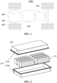
- the battery cell includes an end cover assembly 10, a first housing 20, a second housing 30, a first electrode assembly 40, a second electrode assembly 50, a first end cover assembly 60 and second end cover assembly 70.
- the first housing 20 and the second housing 30 both have openings, the first electrode assembly 40 is received inside the first housing 20, and the second electrode assembly 50 is received inside the second housing 30.
- the opening of the first housing 20 is arranged opposite the opening of the second housing 30, and the end cover assembly 10 is arranged between the first housing 20 and the second housing 30.
- the first end cover assembly 60 is arranged at one end of the first housing 20 that is away from the opening thereof, and the second end cover assembly 70 is arranged at one end of the second housing 30 that is away from the opening thereof.
- the first electrode assembly 40 and the second electrode assembly 50 each may be formed by stacking or winding a first electrode plate and a second electrode plate with opposite polarities, and a separator is generally provided between the first electrode plate and the second electrode plate. Coated parts of the first electrode plate and the second electrode plate constitute main bodies of the first electrode assembly 40 and the second electrode assembly 50, and uncoated parts of the first electrode plate and the second electrode plate respectively constitute two tabs with opposite polarities.
- the first housing 20 and the second housing 30 may have various shapes and sizes, such as a cuboid, a cylinder and a hexagonal prism. Specifically, the first housing 20 and the second housing 30 may be shaped according to the specific shapes and sizes of the first electrode assembly 40 and the second electrode assembly 50.
- the first housing 20 and the second housing 30 may be made of various materials, such as copper, iron, aluminum, stainless steel, an aluminum alloy, and plastic, which will not be specially limited in the embodiments of the present application.
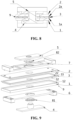
- the end cover assembly 10 includes a first cover plate 1, a second cover plate 2 and an anti-rotation device 9.
- the first cover plate 1 is configured to close a first housing 20, the first housing 20 is configured to receive a first electrode assembly 40, the second cover plate 2 is configured to close a second housing 30, the second housing 30 is configured to receive a second electrode assembly 50, the second cover plate 2 and the first cover plate 1 are arranged opposite to each other in a first direction so as to arrange the first housing 20 and the second housing 30 in the first direction, and the anti-rotation device 9 is configured to prevent a relative rotation between the first cover plate 1 and the second cover plate.
- the first direction is a direction perpendicular to the first cover plate 1 and the second cover plate 2.
- the anti-rotation device 9 it is also possible to prevent the relative rotation between the first cover plate 1 and the second cover plate 2 from affecting the sealing performance of the first housing 20 and the second housing 30, preventing the leakage of the electrode assemblies, which may cause safety accidents.
- the end cover assembly further includes a first insulating member 3 arranged between the first cover plate 1 and the second cover plate 2, such that the first cover plate 1 and the second cover plate 2 are insulated from each other.
- the insulation between the first cover plate 1 and the second cover plate 2 can be realized, and then the first housing 20 closed by the first cover plate 1 and the second housing 30 closed by the second cover plate 2 can be insulated from each other, and are not in communication with each other by means of the first cover plate 1 and the second cover plate 2.
- the anti-rotation device 9 comprises a connecting post 41, the first cover plate 1 is provided with a first through hole 11, the second cover plate 2 is provided with a second through hole 21, one end of the connecting post 41 passes through the first through hole 11 and is configured to be electrically connected to a first electrode assembly 40 in the first housing 20, the other end of the connecting post 41 the second through hole 21 and is configured to be electrically connected to a second electrode assembly 50 in the second housing 30, and the connecting post 41 is non-rotatably engaged with the first through hole 11 and the second through hole 21 respectively.
- the connecting post 41 is a component that electrically connects the first electrode assembly 40 to the second electrode assembly 50, that is, an electrode terminal, which can realize the series connection between the first electrode assembly 40 and the second electrode assembly 50.
- the connecting post 41 by modifying the structure of the connecting post 41, and by providing the non-rotatable engagement between the connecting post 41 and the first through hole 11, the relative rotation between the connecting post 41 and the first cover plate 1 can be prevented; and by providing the non-rotatable engagement between the connecting post 41 and the second through hole 21, the relative rotation between the connecting post 41 and the second cover plate 2 can be prevented, thereby achieving the purpose of preventing the relative rotation between the first cover plate 1 and the second cover plate 2. Therefore, there is no need to add new components for preventing the relative rotation between the first cover plate 1 and the second cover plate 2, and the reduction of the overall weight and volume of the battery cell is facilitated, and the cost can also be saved.
- connecting post 41 may be bonded to a hole wall of the first through hole 11
- the connecting post 41 may be bonded to a hole wall of the second through hole 21, and so on.
- the part of the connecting post 41 passing through the first through hole 11 and the part of the connecting post 41 passing through the second through holes 21 are respectively square structures, and the first through hole 11 and the second through hole 21 are respectively square holes non-rotatably engaged with the corresponding square structures.
- the connecting post 41 is a square structure, and the first through hole 11 and the second through hole 21 are both square holes.
- Such a configuration can prevent the connecting post 41 from rotating in the first through hole 11 and the second through hole 21, that is, the purpose of limiting the rotation of the connecting post 41 relative to the first through hole 11 and the second through hole 21 can be achieved, thereby preventing the connecting post 41 from rotating relative to the first cover plate 1 and the second cover plate 2, so that the connecting post 41 is integrated with a structure non-rotatably engaged with the first cover plate 1 and the second cover plate 2.
- the square holes and the square structure are easy to machine, and there is no need to make too many structural changes to the end cover assembly, resulting in low costs.
- the connecting post 41 is a triangular prism, and the first through hole 11 and the second through hole 21 are both triangular holes; or the connecting post 41 is a pentagonal prism, and the first through hole 11 and the second through hole 21 are both pentagonal holes, and so on.
- the anti-rotation device 9 includes a first bonding structure 1a and a second bonding structure 2a.
- the first insulating member 3 is fixedly bonded to the first cover plate 1 via the first bonding structure 1a, and the first insulating member 3 is fixedly bonded to the second cover plate 2 via the second bonding structure 2a.
- the bonding connection between the first insulating member 3 and the first cover plate 1 can be realized, so as to maintain the relative fixation between the first insulating member 3 and the first cover plate 1, and prevent the first insulating member 3 from rotating relative to the first cover plate 1.
- the bonding connection between the first insulating member 3 and the second cover plate 2 can be realized, so as to maintain the relative fixation between the first insulating member 3 and the second cover plate 2, and prevent the first insulating member 3 from rotating relative to the second cover plate 2, thereby achieving relative stability between the first cover plate 1 and the second cover plate 2, and preventing the relative rotation between the first cover plate 1 and the second cover plate 2.
- the structure is simple and easy to realize.
- the first bonding structure 1a and the second bonding structure 2a may use adhesives and the like.
- one of the first cover plate 1 and the first insulating member 3 has a periphery provided with a first enclosure structure, and the other thereof has a side wall abutting against a side wall of the first enclosure structure to limit a relative rotation between the first cover plate 1 and the first insulating member 3; and one of the second cover plate 2 and the first insulating member 3 has a periphery provided with a second enclosure structure, and the other thereof has a side wall abutting against a side wall of the second enclosure structure to limit a relative rotation between the second cover plate 2 and the first insulating member 3.
- the rotation of the first insulating member 3 relative to the first cover plate 1 can be limited.
- the rotation of the first insulating member 3 relative to the second cover plate 2 can be limited, so as to prevent the relative rotation between the first cover plate 1 and the second cover plate 2, and maintain the relative stability between the first cover plate 1 and the second cover plate 2, thereby improving the torsion resistance of the end cover assembly and therefore of the entire battery cell, and improving the structural stability of the battery cell.
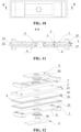
- the first enclosure structure includes a first enclosure 12 and a second enclosure 35.
- the first enclosure 12 is arranged at an edge of the first cover plate 1 in a circumferential direction of the first cover plate 1, and the first insulating member 3 is at least partially received in a recess formed by the combination of the first enclosure 12 and the first cover plate 1, to limit the relative rotation between the first cover plate 1 and the first insulating member 3.
- the second enclosure 35 is arranged at an edge of the first insulating member 3 in a circumferential direction of the first insulating member 3, and the first cover plate 1 is at least partially received in a recess formed by the combination of the second enclosure 35 and the first insulating member 3, to limit the relative rotation between the first cover plate 1 and the first insulating member 3.
- the first enclosure 12 is arranged at the edge of the first cover plate 1 in the circumferential direction of the first cover plate 1 and extends from the first cover plate 1 in a direction approaching the first insulating member 3, the combination of the first enclosure 12 and the first cover plate 1 forms a recess with a receiving space, the first insulating member 3 includes a first protrusion 32, and the first protrusion 32 is received in the recess formed by the combination of the first enclosure 12 and the first cover plate 1.
- the second enclosure 35 is arranged at the edge of the first insulating member 3 in the circumferential direction of the first insulating member 3 and extends from the first insulating member 3 in a direction approaching the first cover plate 1, the combination of the second enclosure 35 and the first insulating member 3 forms a recess with a receiving space, the first cover plate 1 includes a second protrusion 13, and the second protrusion 13 is received in the recess formed by the combination of the second enclosure 35 and the first insulating member 3.
- At least part of the first insulating member 3 can be received in the recess formed by the combination of the first enclosure 12 and the first cover plate 1, so that the rotation of the first insulating member 3 relative to the first cover plate 1 is limited by the first enclosure 12.
- at least part of the first cover plate 1 can be received in the recess formed by the combination of the second enclosure 35 and the first insulating member 3, so that the rotation of the first insulating member 3 relative to the first cover plate 1 is limited by the second enclosure 35.
- the recess formed by the combination of the first enclosure 12 and the first cover plate 1 is non-rotatably engaged with the first protrusion 32.
- the first enclosure 12 is a square structure
- the combination of the first enclosure 12 and the first cover plate 1 forms a square receiving space
- the first protrusion 32 is square, so the first enclosure 12 can limit the rotation of the first insulating member 3 relative to the first cover plate 1.
- the recess formed by the combination of the second enclosure 35 and the first insulating member 3 is non-rotatably engaged with the second protrusion 13.
- the second enclosure 35 is a square structure, and the combination of the second enclosure 35 and the first insulating member 3 forms a square receiving space, and the second protrusion 13 is square, so the second enclosure 35 can limit the rotation of the first insulating member 3 relative to the first cover plate 1.
- the second enclosure structure includes a third enclosure 23 and a fourth enclosure 33.
- the third enclosure 23 is arranged at an edge of the second cover plate 2 in a circumferential direction of the second cover plate 2, and the first insulating member 3 is at least partially received in a recess formed by the combination of the third enclosure 23 and the second cover plate 2, to limit the relative rotation between the second cover plate 2 and the first insulating member 3.
- the fourth enclosure 33 is arranged at an edge of the first insulating member 3 in a circumferential direction of the first insulating member 3, and the second cover plate 2 is at least partially received in a recess formed by the combination of the fourth enclosure 33 and the first insulating member 3, to limit the relative rotation between the second cover plate 2 and the first insulating member 3.
- the third enclosure 23 is arranged at the edge of the second cover plate 2 in the circumferential direction of the second cover plate 2 and extends from the second cover plate 2 in a direction approaching the first insulating member 3, the combination of the third enclosure 23 and the second cover plate 2 forms a recess with a receiving space, the first insulating member 3 includes a third protrusion 34, and the third protrusion 34 is received in the recess formed by the combination of the third enclosure 23 and the second cover plate 2.
- the fourth enclosure 33 is arranged at the edge of the first insulating member 3 in the circumferential direction of the first insulating member 3 and extends from the first insulating member 3 in a direction approaching the second cover plate 2, the combination of the fourth enclosure 33 and the first insulating member 3 forms a recess with a receiving space, the second cover plate 2 includes a fourth protrusion 22, and the fourth protrusion 22 is received in the recess formed by the combination of the fourth enclosure 33 and the first insulating member 3.
- At least part of the first insulating member 3 can be received in the recess formed by the combination of the third enclosure 23 and the second cover plate 2, so that the rotation of the first insulating member 3 relative to the second cover plate 2 is limited by the third enclosure 23.
- at least part of the second cover plate 2 can be received in the recess formed by the combination of the fourth enclosure 33 and the first insulating member 3, so that the rotation of the first insulating member 3 relative to the second cover plate 2 is limited by the fourth enclosure 33.
- the recess formed by the combination of the third enclosure 23 and the second cover plate 2 is non-rotatably engaged with the third protrusion 34.
- the third enclosure 23 is a square structure, the combination of the third enclosure 23 and the second cover plate 2 forms a square receiving space, and the third protrusion 34 is square, so the third enclosure 23 can limit the rotation of the first insulating member 3 relative to the second cover plate 2.
- the recess formed by the combination of the fourth enclosure 33 and the first insulating member 3 is non-rotatably engaged with the fourth protrusion 22.
- the fourth enclosure 33 is a square structure, and the combination of the fourth enclosure 33 and the first insulating member 3 forms a square receiving space, and the fourth protrusion 22 is square, so the fourth enclosure 33 can limit the rotation of the first insulating member 3 relative to the second cover plate 2.
- first electrode assembly 40 and the second electrode assembly 50 are connected to each other.
- a first tab 40a on the first electrode assembly 40 and a second tab 50a on the second electrode assembly 50 are electrically connected to each other via the end cover assembly 10, the other tab of the first electrode assembly 40 is connected to a terminal of the first end cover assembly 60, and the other tab of the second electrode assembly 50 is connected to a terminal of the second end cover assembly 70.
- the anti-rotation device 9 includes a first anti-rotation portion 91 and a second anti-rotation portion 93.
- the first anti-rotation portion 91 is arranged between the first insulating member 3 and the first cover plate 1 and is configured to prevent the relative rotation between the first insulating member 3 and the first cover plate 1
- the second anti-rotation portion 93 is arranged between the first insulating member 3 and the second cover plate 2 and is configured for the relative rotation between the first insulating member 3 and the second cover plate 2.
- the arrangement of the first anti-rotation portion 91 between the first insulating member 3 and the first cover plate 1 can prevent the relative rotation between the first insulating member 3 and the first cover plate 1.
- the arrangement of the second anti-rotation portion 93 between the first insulating member 3 and the second cover plate 2 can prevent the relative rotation between the first insulating member 3 and the second cover plate 2.
- the torsion resistance between the first cover plate 1 and the second cover plate 2 is also improved, and the torsion resistance between the first housing 20 connected to the first cover plate 1 and the second housing 30 connected to the second cover plate 2 is thus also improved, so that for the battery cell equipped with the end cover assembly, the relative stability between the first cover plate and the second cover plate can be maintained, the torsion resistance of the entire battery cell can be effectively improved, and the structural stability of the battery cell can be improved.
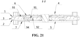
- one of the first cover plate 1 and the first insulating member 3 is provided with a first groove 92, the other thereof is provided with the first anti-rotation portion 91, and the first anti-rotation portion 91 is embedded in the first groove 92; and one of the second cover plate 2 and the first insulating member 3 is provided with a second groove 94, the other thereof is provided with the second anti-rotation portion 93, and the second anti-rotation portion 93 is embedded in the second groove 94.
- one of the first cover plate 1 and the first insulating member 3 is provided with the first anti-rotation portion 91 and the other thereof is provided with the corresponding first groove 92
- one of the first insulating member 3 and the second cover plate 2 is provided with the second anti-rotation portion 93 and the other thereof is provided with the corresponding second groove 94.
- the first anti-rotation portion 91 is arranged on the second cover plate 2, the first anti-rotation portion 91 protrudes from a surface of the second cover plate 2 close to the first insulating member 3 in the direction approaching the first insulating member 3, the first groove 92 of the first insulating member 3, the first groove 92 extends from a side surface of the first insulating member 3 close to the second cover plate 2 in the direction approaching the first cover plate 1, and the first anti-rotation portion 91 is embedded in the first groove 92; and the second anti-rotation portion 93 is arranged on the first insulating member 3, the second anti-rotation portion 93 protrudes from a surface of the first insulating member 3 close to the first cover plate 1 in the direction approaching the first cover plate 1, the first cover plate 1 is provided with a second groove 94, the second groove 94 extends from a side surface of the first cover plate 1 close to the first insulating member 3 in a direction away from the first
- the second cover plate 2 and the first insulating member 3 arranged adjacent to each other are respectively provided with the corresponding first anti-rotation portion 91 and first groove 92, while the first insulating member 3 and the first cover plate 1 arranged adjacent to each other are respectively provided with the corresponding second anti-rotation portion 93 and second groove 94, the first insulating member 3 provided with both the first groove 92 and the second anti-rotation portion 93 is located between the first cover plate 1 and the second cover plate 2, the protruding directions of the first anti-rotation portion 91 and the second anti-rotation portion 93 are the same, and two concave-convex engagement structures in the same direction are formed between the first cover plate 1, the first insulating member 3 and the second cover plate 2, so that a better effect of preventing the relative rotation between the first cover plate 1 and the first insulating member 3 and between the first insulating member 3 and the second cover plate 2 is provided.
- the first anti-rotation portion 91 is provided on the first cover plate 1, the first insulating member 3 is provided with the first groove 92, the second anti-rotation portion 93 is provided on the first insulating member 3, the second cover plate 2 is provided with the second groove 94, the first anti-rotation portion 91 is embedded in the first groove 92, and the second anti-rotation portion 93 is embedded in the second groove 94.
- two concave-convex engagement structures in the same direction are also formed between the first cover plate 1, the first insulating member 3 and the second cover plate 2, but the protruding direction of the concave-convex engagement structure is opposite to that of the concave-convex engagement structure in the embodiments as shown in Figs. 15 to 18 .
- a projection of the first groove 92 and a projection of the second anti-rotation portion 93 are offset from each other.
- the projection of the first groove 92 and the projection of the second anti-rotation portion 93 are offset from each other, so that the engagement structure of the first anti-rotation portion 91 and the first groove 92 and the engagement structure of the second anti-rotation portion 93 and the second groove 94 are dispersed in different positions, thereby increasing the coverage of the anti-rotation device 9 and improving the anti-rotation effect.
- a projection of the first groove 92 falls within the range of a projection of the second anti-rotation portion 93.
- the projection of the first groove 92 falls within the range of the projection of the second anti-rotation portion 93, that is, the first groove 92 is arranged directly below a protruding position of the second anti-rotation portion 93, and a recessed position of the first groove 92 is exactly opposed to the protruding position of the second anti-rotation portion 93, so that two concave-convex engagement structures nested with each other can be formed between the first cover plate 1, the first insulating member 3 and the second cover plate 2, thereby effectively enhancing the overall strength of the anti-rotation device 9 and improving the anti-rotation effect.
- the first groove 92 is provided on the first insulating member 3
- the second groove 94 is provided on the second cover plate 2
- the first anti-rotation portion 91 at least partially extends into the second groove 94 in the embedding direction of the first anti-rotation portion 91.
- At least part of the first anti-rotation portion 91 can extend into the second groove 94, that is, the depth h of the first groove 92 is greater than the thickness t of the first insulating member 3, so that part of the second groove 94 is situated in the first groove 92, and the second anti-rotation portion 93 is located between a groove wall of the first groove 92 and a groove wall of the second groove 94.
- the first groove 92 may include a part that is higher than the side surface of the first insulating member 3 close to the second cover plate 2, this part may be embedded in the second groove 94 provided on the second cover plate 2, and the first anti-rotation portion 91 engaged with the first groove 92 can thus also partially enter the second groove 94, so that the torsional force on the first cover plate 1 can be directly transferred to the second cover plate 2 through the first anti-rotation portion 91 by means of the second anti-rotation portion 93 of the first insulating member 3, thereby reducing the strength requirements for the first insulating member 3 and allowing the thickness of the first insulating member 3 to be appropriately reduced.
- the part of the first anti-rotation portion 91 that extends into the second groove 94 has an extension dimension greater than or equal to 0.2 mm.
- the part of the first anti-rotation portion 91 that extends into the second groove 94 has an extension dimension greater than or equal to 0.2 mm, that is, the difference between the depth h of the first groove 92 and the thickness t of the first insulating member 3 is greater than or equal to 0.2 mm, so that the torsional force on the first cover plate 1 can be directly transferred to the second cover plate 2 through the first anti-rotation portion 91, thereby improving the effects of force transfer and anti-rotation.
- the shapes of the first anti-rotation portion 91 and the second anti-rotation portion 93 may be selected in various ways, such as a cylindrical shape, a square shape, and the like.
- the shapes of the first groove 92 and the second groove 94 match the shapes of the first anti-rotation portion 91 and the second anti-rotation portion 93 respectively.
- the end cover assembly 10 further includes a first conductive member 4 and a second conductive member 5.
- the second conductive member 5 is arranged on the side of the second cover plate 2 away from the first insulating member 3, and the first conductive member 4 includes a connecting post 41 and a limiting portion 42.
- the limiting portion 42 is arranged on the side of the first cover plate 1 away from the first insulating member 3.
- the first cover plate 1 is provided with a first through hole 11
- the second cover plate 2 is provided with a second through hole 21, and the first insulating member 3 is provided with a third through hole 31.
- the connecting post 41 passes through the first through hole 11, the third through hole 31 and the second through hole 21 in sequence, and is connected to the second conductive member 5.
- the limiting portion 42 is configured to limit the movement of the first conductive member 4 in an axis direction of the first through hole 11.
- the electrical connection between the first electrode assembly 40 in the first housing 20 and the second electrode assembly 50 in the second housing 30 is realized by means of the first conductive member 4 and the second conductive member 5.
- the second conductive member 5 is provided with a fourth through hole 51, and the connecting post 41 passes through the fourth through hole 51 to realize the connection between the first conductive member 4 and the second conductive member 5.
- the end cover assembly 10 further includes a second insulating member 6 and a third insulating member 7.
- the second insulating member 6 is arranged between the first cover plate 1 and the limiting portion 42, and the third insulating member 7 is arranged between the second cover plate 2 and the second conductive member 5.
- the second insulating member 6 is provided with a fifth through hole 61
- the third insulating member 7 is provided with a sixth through hole 71
- the connecting post 41 passes through the fifth through hole 61 and the sixth through hole 71.
- the second insulating member 6 can electrically isolate the first cover plate 1 from the limiting portion 42 of the first conductive member 4; and the third insulating member 7 can electrically isolate the second cover plate 2 from the second conductive member 5.
- the end cover assembly 10 further includes a first sealing member 81, the first sealing member 81 is arranged between the limiting portion 42 and the second insulating member 6, the first sealing member 81 is provided with a seventh through hole, the connecting post 41 passes through the seventh through hole, and the first sealing member 81 is axially embedded in the fifth through hole 61 and the first through hole 11 to isolate the first cover plate 1 from the limiting portion 42 and the first cover plate 1 from the connection post 41; and/or the end cover assembly further includes a second sealing member 82, the second sealing member 82 is arranged between the second conductive member 5 and the third insulating member 7, the second sealing member 82 is provided with an eighth through hole, the connecting post 41 passes through the eighth through hole, and the second sealing member 82 is axially embedded in the sixth through hole 71 and the second through hole 21 to isolate the second cover plate 2 from the second conductive member 5 and the second cover plate 2 from the connecting post 41.
- the first sealing member 81 it is possible to tightly connect the limiting portion 42 of the first conductive member 4 to the second insulating member 6 in an axial direction, to isolate the limiting portion 42 of the first conductive member 4 from the first cover plate 1 in the axial direction, and to isolate the first cover plate 1 from the connecting post 41 of the first conductive member 4 in a radial direction.
- the second sealing member 82 it is possible to tightly connect the second conductive member 5 to the third insulating member 7 in an axial direction, to isolate the second conductive member 5 from the second cover plate 2 in the axial direction, and to isolate the second cover plate 2 from the connecting post 41 of the first conductive member 4 in a radial direction.
- the battery cell includes an end cover assembly 10, a first housing 20, a second housing 30, a first electrode assembly 40, a second electrode assembly 50, a first end cover assembly 60 and second end cover assembly 70.
- the first housing 20 and the second housing 30 both have openings, the first electrode assembly 40 is received inside the first housing 20, and the second electrode assembly 50 is received inside the second housing 30.
- the opening of the first housing 20 is arranged opposite the opening of the second housing 30, and the end cover assembly 10 is arranged between the first housing 20 and the second housing 30.
- the first end cover assembly 60 is arranged at one end of the first housing 20 that is away from the opening thereof, and the second end cover assembly 70 is arranged at one end of the second housing 30 that is away from the opening thereof.
- the first housing 20 and the second housing 30 are both square housings.
- the end cover assembly includes a first cover plate 1, a second cover plate 2, a first insulating member 3, a first conductive member 4, a second conductive member 5, a second insulating member 6, a third insulating member 7, a first sealing member 81, and a second sealing member 82.
- the first insulating member 3 is arranged between the first cover plate 1 and the second cover plate 2 to insulate the first cover plate 1 from the second cover plate 2.
- the second insulating member 6 is arranged on the side of the first cover plate 1 away from the first insulating member 3, and the third insulating member 7 is arranged on the side of the second cover plate 2 away from the first insulating member 3.
- the first conductive member 4 includes a connecting post 41 and a limiting portion 42.
- the limiting portion 42 is arranged on the side of the second insulating member 6 away from the first cover plate 1.
- the connecting post 41 is connected to the side of the limiting portion 42 close to the second insulating member 6.
- the second conductive member 5 is arranged on the side of the third insulating member 7 away from the second cover plate 2.
- the first cover plate 1 is provided with a first through hole 11, the second cover plate 2 is provided with a second through hole 21, the first insulating member 3 is provided with a third through hole 31, and the second conductive member 5 is provided with a fourth through hole 51, the second insulating member 6 is provided with a fifth through hole 61, the third insulating member 7 is provided with a sixth through hole 71, the first sealing member 81 is provided with a seventh through hole, and the second sealing member 82 is provided with an eighth through hole.
- the connecting post 41 passes through the seventh through hole, the fifth through hole 61, the first through hole 11, the third through hole 31, the second through hole 21, the sixth through hole 71, the eighth through hole and the fourth through hole 51 in sequence, and is connected to the second conductive member 5.
- the limiting portion 42 is configured to limit the movement of the first conductive member 4 in an axis direction of the first through hole 11.
- the first cover plate 1, the second cover plate 2, the first insulating member 3, the limiting portion 42 of the first conductive member 4, the second conductive member 5, the second insulating member 6 and the third insulating member 7 are all in a square shape.
- a first electrode assembly 40 in the first housing 20 and a second electrode assembly 50 in the second housing 30 are electrically connected to each other via the first conductive member 4 and the second conductive member 5.
- the first sealing member 81 is arranged between the limiting portion 42 and the second insulating member 6, so that it is possible to tightly connect the limiting portion 42 of the first conductive member 4 to the second insulating member 6 in an axial direction, to isolate the limiting portion 42 of the first conductive member 4 from the first cover plate 1 in the axial direction, and to isolate the first cover plate 1 from the connecting post 41 of the first conductive member 4 in a radial direction.
- the second sealing member 82 is arranged between the second conductive member 5 and the third insulating member 7, so that it is possible to tightly connect the second conductive member 5 to the third insulating member 7 in an axial direction, to isolate the second conductive member 5 from the second cover plate 2 in the axial direction, and to isolate the second cover plate 2 from the connecting post 41 of the first conductive member 4 in a radial direction.
- the part of the connecting post 41 that passes through the first through hole 11 is a square structure, and the first through hole 11 is a square hole that is non-rotatably engaged with the square structure, so as to limit the relative rotation between the connecting post 41 and the first cover plate 1; and the part of the connecting post 41 that passes through the second through hole 21 is a square structure, and the second through hole 21 is a square hole that is non-rotatably engaged with the square structure, so as to limit the relative rotation between the connecting post 41 and the second through hole 21, thereby achieving the purpose of limiting the relative rotation between the first cover plate 1 and the second cover plate 2.
- the first insulating member 3 is fixedly bonded to the first cover plate 1 via a first bonding structure 1a, and the first insulating member 3 is fixedly bonded to the second cover plate 2 via a second bonding structure 2a.
- the relative fixation between the first cover plate 1 and the first insulating member 3 is realized by means of the first bonding structure 1a
- the relative fixation between the second cover plate 2 and the first insulating member 3 is realized by means of the second bonding structure 2a, so as to achieve the purpose of preventing the relative rotation between the first cover plate 1 and the second cover plate 2.
- the anti-rotation device 9 includes a first enclosure 12 and a fourth enclosure 33.
- the first enclosure 12 is arranged at an edge of the first cover plate 1 in a circumferential direction of the first cover plate 1.
- the first insulating member 3 includes a first protrusion 32.
- the first protrusion 32 is received in a recess formed by the combination of the first enclosure 12 and the first cover plate 1, so as to limit the relative rotation between the first cover plate 1 and the first insulating member 3.
- the fourth enclosure 33 is arranged at an edge of the first insulating member 3 in a circumferential direction of the first insulating member 3.
- the second cover plate 2 includes a fourth protrusion 22.
- the fourth protrusion 22 is received in a recess formed by the combination of the fourth enclosure 33 and the first insulating member 3, so as to limit the relative rotation between the second cover plate 2 and the first insulating member 3, thereby achieving the purpose of preventing the relative rotation between the first cover plate 1 and the second cover plate 2.
- the anti-rotation device 9 includes a second enclosure 35 and a third enclosure 23.
- the second enclosure 35 is arranged at an edge of the first insulating member 3 in a circumferential direction of the first insulating member 3.
- the first cover plate 1 includes a second protrusion 13.
- the second protrusion 13 is received in a recess formed by the combination of the second enclosure 35 and the first insulating member 3, so as to limit the relative rotation between the first cover plate 1 and the first insulating member 3.
- the third enclosure 23 is arranged at an edge of the second cover plate 2 in a circumferential direction of the second cover plate 2.
- the first insulating member 3 includes a third protrusion 34.
- the third protrusion 34 is received in a recess formed by the combination of the third enclosure 23 and the second cover plate 2, so as to limit the relative rotation between the second cover plate 2 and the first insulating member 3, thereby achieving the purpose of preventing the relative rotation between the first cover plate 1 and the second cover plate 2.
- a first tab 40a on the first electrode assembly 40 and a second tab 50a on the second electrode assembly 50 are electrically connected to each other via the end cover assembly 10, the other tab of the first electrode assembly 40 is connected to a terminal of the first end cover assembly 60, and the other tab of the second electrode assembly 50 is connected to a terminal of the second end cover assembly 70.
- the anti-rotation device 9 includes a first anti-rotation portion 91 and a second anti-rotation portion 93.
- the first anti-rotation portion 91 is provided on the second cover plate 2
- the first insulating member 3 is provided with the first groove 92
- the second anti-rotation portion 93 is provided on the first insulating member 3
- the first cover plate 1 is provided with the second groove 94
- the first anti-rotation portion 91 is embedded in the first groove 92
- the second anti-rotation portion 93 is embedded in the second groove 94.
- the purpose of preventing the relative rotation between the first cover plate 1 and the second cover plate 2 is achieved through the engagement of the first anti-rotation portion 91 and the first groove 92 and the engagement of the second anti-rotation portion 93 and the second groove 94.
- the first anti-rotation portion 91 is provided on the first cover plate 1, the first insulating member 3 is provided with the first groove 92, the second anti-rotation portion 93 is provided on the first insulating member 3, the second cover plate 2 is provided with the second groove 94, the first anti-rotation portion 91 is embedded in the first groove 92, and the second anti-rotation portion 93 is embedded in the second groove 94.
- the purpose of preventing the relative rotation between the first cover plate 1 and the second cover plate 2 is also achieved through the engagement of the first anti-rotation portion 91 and the first groove 92 and the engagement of the second anti-rotation portion 93 and the second groove 94, but the protruding direction of the concave-convex engagement structure is opposite to that of the concave-convex engagement structure in the embodiments as shown in Figs. 15 to 18 .
- a projection of the first groove 92 falls within the range of a projection of the second anti-rotation portion 93.
- a projection of the first groove 92 and a projection of the second anti-rotation portion 93 are offset from each other.
Landscapes
- Chemical & Material Sciences (AREA)
- Chemical Kinetics & Catalysis (AREA)
- Electrochemistry (AREA)
- General Chemical & Material Sciences (AREA)
- Sealing Battery Cases Or Jackets (AREA)
Abstract
Description
- The present application relates to the technical field of batteries, and particularly to an end cover assembly, a battery cell, a battery and an electrical apparatus.
- Energy saving and emission reduction is the key to the sustainable development of automotive industry, electric vehicles have become an important part of the sustainable development of automotive industry due to their advantages of energy saving and environmental protection. For electric vehicles, battery technology is an important factor related to their development.
- During the use of a battery, the relative stability of some components is related to the overall quality of the battery; especially for some types of combined battery cells, a shell thereof is generally formed by at least two housings connected end-to-end, and two adjacent shells are connected to each other via an end cover having an integrated structure. Such an end cover usually includes two end cover plates arranged opposite to each other, and the two end cover plates are respectively configured to cover openings of the two adjacent housings. The relative stability between these components directly affects the structural stability of the battery cell.
- The present application provides an end cover assembly, a battery cell, a battery and an electrical apparatus, which can maintain the relative stability between a first cover plate and a second cover plate, and improve the structural stability of the battery cell.
- In a first aspect, the present application provides an end cover assembly, including a first cover plate, a second cover plate and an anti-rotation device, wherein the first cover plate is configured to close a first housing, the second cover plate is configured to close a second housing, and the second cover plate and the first cover plate are arranged opposite to each other in a first direction; and the anti-rotation device is configured to prevent a relative rotation between the first cover plate and the second cover plate.
- In these embodiments, with the arrangement of the anti-rotation device between the first cover plate and the second cover plate, it is possible to prevent the relative rotation between the first cover plate and the second cover plate, and maintain the relative stability between the first cover plate and the second cover plate, thereby improving the torsion resistance of the end cover assembly and therefore of the entire battery cell, and improving the structural stability of the battery cell.
- In some embodiments, the end cover assembly further includes a first insulating member arranged between the first cover plate and the second cover plate, such that the first cover plate and the second cover plate are insulated from each other.
- With the arrangement of the first insulating member, the insulation between the first cover plate and the second cover plate can be realized, and then the first housing closed by the first cover plate and the second housing closed by the second cover plate can be insulated from each other, and are not in communication with each other by means of the first cover plate and the second cover plate.
- In some embodiments, the anti-rotation device includes a connecting post, the first cover plate is provided with a first through hole, the second cover plate is provided with a second through hole, one end of the connecting post passes through the first through hole and is configured to be electrically connected to a first electrode assembly in the first housing, the other end of the connecting post the second through hole and is configured to be electrically connected to a second electrode assembly in the second housing, and the connecting post is non-rotatably engaged with the first through hole and the second through hole respectively.
- In these embodiments, the connecting post is a component that electrically connects the first electrode assembly to the second electrode assembly, that is, an electrode terminal, which can realize the series connection between the first electrode assembly and the second electrode assembly. In these embodiments, by modifying the structure of the connecting post, and by providing the non-rotatable engagement between the connecting post and the first through hole, the relative rotation between the connecting post and the first cover plate can be prevented; and by providing the non-rotatable engagement between the connecting post and the second through hole, the relative rotation between the connecting post and the second cover plate can be prevented, thereby preventing the relative rotation between the first cover plate and the second cover plate. Therefore, there is no need to add new components for preventing the relative rotation between the first cover plate and the second cover plate, the reduction of the overall weight and volume of the battery cell is facilitated, and the cost can also be saved.
- In some embodiments, the part of the connecting post passing through the first through hole and the part of the connecting post passing through the second through holes are respectively square structures, and the first through hole and the second through hole are respectively square holes non-rotatably engaged with the corresponding square structures. Such a configuration can prevent the connecting post from rotating in the first through hole and the second through hole, that is, the purpose of limiting the rotation of the connecting post relative to the first through hole and the second through hole can be achieved, thereby preventing the connecting post from rotating relative to the first cover plate and the second cover plate, so that the connecting post is integrated with a structure non-rotatably engaged with the first cover plate and the second cover plate. The square holes and the square structures are easy to machine, and there is no need to make too many structural changes to the end cover assembly, resulting in low costs.
- In some embodiments, the anti-rotation device further includes a first bonding structure and a second bonding structure. The first insulating member is fixedly bonded to the first cover plate via the first bonding structure, and the first insulating member is fixedly bonded to the second cover plate via the second bonding structure.
- With the arrangement of the first bonding structure, the bonding connection between the first insulating member and the first cover plate can be realized, so as to maintain the relative fixation between the first insulating member and the first cover plate, and prevent the first insulating member from rotating relative to the first cover plate. With the arrangement of the second bonding structure, the bonding connection between the first insulating member and the second cover plate can be realized, so as to maintain the relative fixation between the first insulating member and the second cover plate, and prevent the first insulating member from rotating relative to the second cover plate, thereby achieving relative stability between the first cover plate and the second cover plate, and preventing the relative rotation between the first cover plate and the second cover plate. The structure is simple and easy to realize.
- In some embodiments, one of the first cover plate and the first insulating member has a periphery provided with a first enclosure structure, and the other thereof has a side wall abutting against a side wall of the first enclosure structure to limit a relative rotation between the first cover plate and the first insulating member; and
one of the second cover plate and the first insulating member has a periphery provided with a second enclosure structure, and the other thereof has a side wall abutting against a side wall of the second enclosure structure to limit a relative rotation between the second cover plate and the first insulating member. - With the arrangement of the first enclosure structure, the rotation of the first insulating member relative to the first cover plate can be limited. With the arrangement of the second enclosure structure, the rotation of the first insulating member relative to the second cover plate can be limited, so as to prevent the relative rotation between the first cover plate and the second cover plate, and maintain the relative stability between the first cover plate and the second cover plate, thereby improving the torsion resistance of the end cover assembly and therefore of the entire battery cell, and improving the structural stability of the battery cell.
- In some embodiments, the anti-rotation device includes a first anti-rotation portion and a second anti-rotation portion, wherein the first anti-rotation portion is arranged between the first insulating member and the first cover plate and is configured to prevent the relative rotation between the first insulating member and the first cover plate, and the second anti-rotation portion is arranged between the first insulating member and the second cover plate and is configured for the relative rotation between the first insulating member and the second cover plate.
- In these embodiments, the arrangement of the first anti-rotation portion between the first insulating member and the first cover plate can prevent the relative rotation between the first insulating member and the first cover plate. The arrangement of the second anti-rotation portion between the first insulating member and the second cover plate can prevent the relative rotation between the first insulating member and the second cover plate. After the relative rotation between the first insulating member and the first cover plate and the relative rotation between the first insulating member and the second cover plate are respectively limited by the first anti-rotation portion and the second anti-rotation portion, the torsion resistance between the first cover plate and the second cover plate is also improved, and the torsion resistance between the first housing connected to the first cover plate and the second housing connected to the second cover plate is thus also improved, so that for the battery cell equipped with the end cover assembly, the relative stability between the first cover plate and the second cover plate can be maintained, the torsion resistance of the entire battery cell can be effectively improved, and the structural stability of the battery cell can be improved.
- In some embodiments, one of the first cover plate and the first insulating member is provided with a first groove, the other thereof is provided with the first anti-rotation portion, and the first anti-rotation portion is embedded in the first groove; and
one of the second cover plate and the first insulating member is provided with a second groove, the other thereof is provided with the second anti-rotation portion, and the second anti-rotation portion is embedded in the second groove. - In these embodiments, one of the first cover plate and the first insulating member is provided with the first anti-rotation portion and the other thereof is provided with the corresponding first groove, and one of the first insulating member and the second cover plate is provided with the second anti-rotation portion and the other thereof is provided with the corresponding second groove. Through the engagement between the first anti-rotation portion and the first groove and the engagement between the second anti-rotation portion and the second groove, a better effect of preventing the relative rotation between the first cover plate and the first insulating member and between the first insulating member and the second cover plate is provided.
- In some embodiments, in a plane perpendicular to an embedding direction of the first anti-rotation portion, a projection of the first groove and a projection of the second anti-rotation portion are offset from each other.
- In these embodiments, the projection of the first groove and the projection of the second anti-rotation portion are offset from each other, so that the engagement structure of the first anti-rotation portion and the first groove and the engagement structure of the second anti-rotation portion and the second groove are dispersed in different positions, thereby increasing the coverage of the anti-rotation device and improving the anti-rotation effect.
- In some embodiments, in a plane perpendicular to an embedding direction of the first anti-rotation portion, a projection of the first groove falls within the range of a projection of the second anti-rotation portion.
- In these embodiments, the projection of the first groove falls within the range of the projection of the second anti-rotation portion, that is, the first groove is arranged directly below a protruding position of the second anti-rotation portion, and a recessed position of the first groove is exactly opposed to the protruding position of the second anti-rotation portion, so that two concave-convex engagement structures nested with each other can be formed between the first cover plate, the first insulating member and the second cover plate, thereby effectively enhancing the overall strength of the anti-rotation device and improving the anti-rotation effect.
- In some embodiments, the first groove is provided on the first insulating member, the second groove is provided on the second cover plate, and the first anti-rotation portion at least partially extends into the second groove in the embedding direction of the first anti-rotation portion.
- In these embodiments, at least part of the first anti-rotation portion can extend into the second groove, that is, the depth of the first groove is greater than the thickness of the first insulating member, so that part of the second groove is situated in the first groove, and the second anti-rotation portion is located between a groove wall of the first groove and a groove wall of the second groove. Such an arrangement has the advantages that the first anti-rotation portion engaged with the first groove can also partially enter the second groove, so that the torsional force on the first cover plate can be directly transferred to the second cover plate through the first anti-rotation portion by means of the second anti-rotation portion of the first insulating member, thereby reducing the strength requirements for the first insulating member and allowing the thickness of the first insulating member to be appropriately reduced.
- In some embodiments, in the embedding direction of the first anti-rotation portion, the part of the first anti-rotation portion that extends into the second groove has an extension dimension greater than or equal to 0.2 mm.
- In these embodiments, the part of the first anti-rotation portion that extends into the second groove has an extension dimension greater than or equal to 0.2 mm, that is, the difference between the depth of the first groove and the thickness of the first insulating member is greater than or equal to 0.2 mm, so that the torsional force on the first cover plate can be directly transferred to the second cover plate through the first anti-rotation portion, thereby improving the effects of force transfer and anti-rotation.
- In a second aspect, the present application provides a battery cell, including the end cover assembly described above.
- In a third aspect, the present application provides a battery, including a box and the battery cell described above, wherein the battery cell is arranged in the box, and the battery cell is configured to supply electric energy.
- In a fourth aspect, the present application provides an electrical apparatus, including the battery cell described above, the battery cell being configured to supply electric energy to the electrical apparatus; or including the battery described above, the battery being configured to supply electric energy to the electrical apparatus.
- The above description is only a summary of the technical solutions of the present application. In order to be able to understand the technical means of the present application more clearly, the technical means can be implemented according to the content of the specification. Furthermore, to make the above and other objectives, features and advantages of the present application more comprehensible, specific implementations of the present application are exemplified below.
- In order to more clearly illustrate the technical solutions of the embodiments of the present application, the drawings to be used in the description of the embodiments of the present application will be described briefly below. Obviously, the drawings in the following description are merely some embodiments of the present application. For those skilled in the art, other drawings can also be obtained according to these drawings without any creative effort.
-
Fig. 1 is a schematic structural diagram of an electrical apparatus disclosed in some embodiments of the present application; -
Fig. 2 is a schematic structural diagram of a battery disclosed in some embodiments of the present application; -
Fig. 3 is an exploded view of a battery cell disclosed in some embodiments of the present application; -
Fig. 4 is a schematic structural diagram of a battery cell disclosed in some embodiments of the present application; -
Fig. 5 is an exploded view of an end cover assembly disclosed in some embodiments of the present application; -
Fig. 6 is a top view of an end cover assembly disclosed in some embodiments of the present application in an assembled state; -
Fig. 7 is a cross-sectional view along the section A-A inFig. 6 ; -
Fig. 8 is a cross-sectional view of the interior of an end cover assembly disclosed in some embodiments of the present application; -
Fig. 9 is an exploded view of an end cover assembly disclosed in some other embodiments of the present application; -
Fig. 10 is a top view of an end cover assembly disclosed in some other embodiments of the present application in an assembled state; -
Fig. 11 is a cross-sectional view along the section B-B inFig. 10 ; -
Fig. 12 is an exploded view of an end cover assembly disclosed in still some other embodiments of the present application; -
Fig. 13 is a side view of a battery cell disclosed in some embodiments of the present application; -
Fig. 14 is a cross-sectional view along the section C-C inFig. 13 ; -
Fig. 15 is an exploded view of the end cover assembly in the embodiments ofFigs. 13 and 14 ; -
Fig. 16 is a top view of the end cover assembly in the embodiments ofFigs. 13 and 14 ; -
Fig. 17 is a cross-sectional view along the section D-D inFig. 16 ; -
Fig. 18 is an enlarged view of part E inFig. 17 ; -
Fig. 19 is an exploded view of an end cover assembly disclosed in yet some other embodiments of the present application; -
Fig. 20 is a top view of an end cover assembly disclosed in yet some other embodiments of the present application; and -
Fig. 21 is a cross-sectional view along the section F-F inFig. 12 . - In the accompanying drawings, the figures are not necessarily drawn to scale.
- List of reference signs:
- 1000, vehicle; 100, battery; 200, axle; 300, wheel; 400, motor; 500, controller;
- 101, battery cell; 102, box; 102a, box body; 102b, cover body;
- 10, end cover assembly; 20, first housing; 30, second housing; 40, first electrode assembly; 40a, first tab; 50, second electrode assembly; 50a, second tab; 60, first end cover assembly; 70, second end cover assembly;
- 1, first cover plate; 1a, first bonding structure; 11, first through hole; 12, first enclosure; 13, second protrusion; 2, second cover plate; 2a, second bonding structure; 21, second through hole; 22, fourth protrusion; 23, third enclosure; 3, first insulating member; 31, third through hole; 32, first protrusion; 33, fourth enclosure; 34, third protrusion; 35, second enclosure; 4, first conductive member; 41, connecting post; 42, limiting portion; 5, second conductive member; 51, fourth through hole; 6, second insulating member; 61, fifth through hole; 7, third insulating member; 71, sixth through hole; 81, first seal; 82, second seal; 9, anti-rotation device; 91, first anti-rotation portion; 92, first groove; 93, second anti-rotation portion; 94, second groove.
- Embodiments of the technical solutions of the present application will be described in detail below with reference to the accompanying drawings. The following embodiments are only used to more clearly illustrate the technical solution of the present application, and therefore are only used as examples and cannot be used to limit the scope of protection of the present application.
- Unless otherwise defined, all technical and scientific terms used herein have the same meaning as commonly understood by those skilled in the art belonging to the technical field of the present application; the terms used herein are intended only for the purpose of describing specific embodiments and are not intended to limit the present application; the terms " including" and "having" and any variations thereof in the specification and the claims of the present application and in the description of drawings above are intended to cover non-exclusive inclusion.
- In the description of the embodiments of the present application, the technical terms "first", "second", and the like are used only to distinguish between different objects, and are not to be understood as indicating or implying a relative importance or implicitly specifying the number, particular order, or primary and secondary relation of the technical features indicated. Furthermore, the term "perpendicular" is not strictly perpendicular, but within the allowable range of errors. Furthermore, the term "parallel" is not strictly parallel, but within the allowable range of error.
- Reference herein to "an embodiment" means that a particular feature, structure, or characteristic described in connection with the embodiment can be included in at least one embodiment of the present application. The appearance of this phrase in various places in the specification does not necessarily refer to the same embodiment, nor is it a separate or alternative embodiment that is mutually exclusive with other embodiments. It is explicitly and implicitly understood by those skilled in the art that the embodiments described herein may be combined with other embodiments.
- In the description of the embodiments of the present application, the term "and/or" is simply a description of an association of associated objects, which indicates that there may exist three relationships, for example, A and/or B may represent three situations: A exists alone, both A and B exist, and B exists alone. In addition, the character "/" herein generally indicates an "or" relationship between the associated objects.
- In the description of the embodiments of the present application, the term "plurality of" means two or more, unless otherwise explicitly and specifically defined. Similarly, "plurality of sets" means two or more sets, and "plurality of pieces" means two or more pieces, unless specifically and specifically limited otherwise.
- In the description of the embodiments of the present application, the orientation or location relationships indicated by the technical terms "center", "longitudinal", "transverse", "length ", "width", "thickness", "up", "down", "front", "back", "left", "right", "vertical", "horizontal", "top", "bottom", "inside", "outside", "clockwise", "counterclockwise", "axial", " radial", "circumferential" and the like are based on the orientation or location relationships shown in the drawings, and are only for convenience and simplification of the description of the embodiments of the present application, but do not indicate or imply that the apparatuses or elements referred to must have particular orientations, be constructed and operated in particular orientations, and therefore cannot be construed as a limitation of the embodiments of the present application.
- In the description of the embodiments of the present application, unless otherwise expressly specified and limited, the technical terms "mounting," "connected," "connecting," "fixing", and the like shall be understood in a broad sense, which, for example, may be a fixed connection, or a detachable connection or an integral connection; may also be a mechanical connection, or an electrical connection; may be a direct connection, or an indirect connection through an intermediate medium, or may be a communication within two elements or an interactive relationship between two elements. For those of ordinary skill in the art, the specific meanings of the above terms in the embodiments of the present application can be understood according to specific situations.
- At present, from the development of market situation, application of traction batteries is becoming more and more extensive. Power batteries are used in energy storage power source systems such as hydraulic, thermal, wind and solar power stations as well as in electric vehicles such as electric bicycles, electric motorcycles and electric cars, and military equipment and aerospace fields. With the continuous expansion of the application field of the power batteries, the market demand is also constantly expanding.
- The inventors of the present application have noticed that with the continuous expansion of the application range of power batteries, the demand for the battery capacity of various electrical apparatus is also increasing. In order to increase the battery capacity as much as possible within a limited storage space, people began to configure a battery cell in a structural form including two electrode assemblies. The two electrode assemblies are connected in series, so that it is possible to omit some intermediate electrical connection components, and also save some space for the battery, thereby providing support for increasing the battery capacity.
- Due to the inclusion of two electrode assemblies, the length of the battery cell is longer than that of a battery cell including one electrode assembly. Therefore, during use, the battery cell may be subjected to lateral shear forces such that the two electrode assemblies are relatively twisted, which may cause problems such as leakage of the electrode assemblies, affecting the overall quality and use safety of the battery cell.
- The inventors have found through research that an anti-rotation device may be provided between a first cover plate and a second cover plate to prevent a relative torsion between the first cover plate and the second cover plate, thereby improving the torsion resistance of the end cover assembly and therefore of the entire battery cell, and preventing the leakage of the electrode assemblies, which may cause safety accidents.
- The end cover assembly described in the embodiments of the present application is suitable for battery cells, batteries, and electrical apparatus using batteries.
- The electrical apparatus may be, for example, a mobile phone, a portable apparatus, a laptop, an electric motorcycle, an electric vehicle, a ship, a spacecraft, an electric toy, or an electric tool. For example, the spacecraft includes an airplane, a rocket, a space shuttle, or a spaceship. The electric toy includes a fixed or mobile electric toy, such as a game console, an electric vehicle toy, an electric ship toy, and an electric airplane toy. The electric tool includes an electric tool for metal cutting, an electric tool for grinding, an electric tool for assembling and an electric tool for railways, such as an electric drill, an electric grinder, an electric wrench, an electric screwdriver, an electric hammer, an electric impact drill, a concrete vibrator, and an electric planer.
- As shown in
Fig. 1 , the electrical apparatus may be avehicle 1000, for example, a new energy vehicle. The new energy vehicle may be an all-electric vehicle, a hybrid electric vehicle, an extended-range electric vehicle, or the like. Alternatively, the electrical apparatus may be an unmanned aerial vehicle, a ship, or the like. Specifically, thevehicle 1000 may include abattery 100, anaxle 200,wheels 300 connected to theaxle 200, amotor 400, and acontroller 500. Thecontroller 500 is configured to control the operation of themotor 400, themotor 400 is configured to drive theaxle 200 to rotate, and the rotation of theaxle 200 drives thewheels 300 to rotate. Thebattery 100 may be arranged at the bottom, head or tail of thevehicle 1000 to supply electric energy for the operation of themotor 400 and other components in the vehicle. - As shown in
Fig. 2 , thebattery 100 includes abattery cell 101 and abox 102. There may be one ormore battery cells 101 in thebattery 100. If there are a plurality ofbattery cells 101, themultiple battery cells 101 may be connected in series or in parallel or in series-parallel. The series-parallel connection means that some of the plurality ofbattery cells 101 are connected in series and the rest are connected in parallel. It is possible that the plurality ofbattery cells 101 are first connected in series or in parallel or in series-parallel to form a plurality of battery modules, and then the battery modules are connected in series or in parallel or in series-parallel to form a whole and received in thebox 102. It is also possible that all thebattery cells 101 are directly connected in series or in parallel or in series-parallel, and then an entirety composed of all thebattery cells 101 is received in thebox 102. - The interior of the
box 102 is a hollow structure. For example, thebox 102 may include abox body 102a and acover body 102b. Thebox body 102a and thecover body 102b are fastened together. For example, thebox body 102a and thecover body 102b each may be a hollow cuboid and each have only one surface with an opening, and the opening of thebox body 102a is arranged opposite the opening of thecover body 102b, and thebox body 102a and thecover body 102b are fastened to each other to form the box body with a closed chamber. It is also possible that thebox body 102a is a cuboid having an opening while thecover body 102b is plate-shaped, or thecover body 102b is a cuboid having an opening while thebox body 102a is plate-shaped, and thebox body 102a and thecover body 102b are arranged opposite each other, and are fastened to each other to form thebox 102 with a closed chamber. At least onebattery cell 101 is assembled in parallel connection or series connection or series-parallel connection, and then placed in the closed chamber formed by fastening thebox body 102a to thecover body 102b. - The
battery cell 101 includes a lithium-ion secondary battery, a lithium-ion primary battery, a lithium sulfur battery, a sodium lithium-ion battery, a sodium-ion battery or a magnesium-ion battery and so on, which will not be limited in the embodiments of the present disclosure. The battery cell may be cylindrical, flat, cuboid or in another shape, which will not be limited by the embodiments of the present disclosure. The battery cells are generally classified into three types depending on the way of package: cylindrical battery cells, prismatic battery cells and pouch battery cells, which will also not be limited in the embodiments of the present disclosure. - In order to enable the improvement principle of the battery cell of the present application to be understood more clearly, the structure of the end cover assembly is described in detail first.
- In some embodiments, as shown in
Figs. 3 and 4 , the battery cell includes anend cover assembly 10, afirst housing 20, asecond housing 30, afirst electrode assembly 40, asecond electrode assembly 50, a firstend cover assembly 60 and secondend cover assembly 70. - The
first housing 20 and thesecond housing 30 both have openings, thefirst electrode assembly 40 is received inside thefirst housing 20, and thesecond electrode assembly 50 is received inside thesecond housing 30. - The opening of the
first housing 20 is arranged opposite the opening of thesecond housing 30, and theend cover assembly 10 is arranged between thefirst housing 20 and thesecond housing 30. The firstend cover assembly 60 is arranged at one end of thefirst housing 20 that is away from the opening thereof, and the secondend cover assembly 70 is arranged at one end of thesecond housing 30 that is away from the opening thereof. - An electrolytic solution is filled in the
first housing 20 and thesecond housing 30 respectively. Thefirst electrode assembly 40 and thesecond electrode assembly 50 each may be formed by stacking or winding a first electrode plate and a second electrode plate with opposite polarities, and a separator is generally provided between the first electrode plate and the second electrode plate. Coated parts of the first electrode plate and the second electrode plate constitute main bodies of thefirst electrode assembly 40 and thesecond electrode assembly 50, and uncoated parts of the first electrode plate and the second electrode plate respectively constitute two tabs with opposite polarities. - The
first housing 20 and thesecond housing 30 may have various shapes and sizes, such as a cuboid, a cylinder and a hexagonal prism. Specifically, thefirst housing 20 and thesecond housing 30 may be shaped according to the specific shapes and sizes of thefirst electrode assembly 40 and thesecond electrode assembly 50. Thefirst housing 20 and thesecond housing 30 may be made of various materials, such as copper, iron, aluminum, stainless steel, an aluminum alloy, and plastic, which will not be specially limited in the embodiments of the present application. - Referring to
Fig. 5 , in some embodiments of the present application, theend cover assembly 10 includes afirst cover plate 1, asecond cover plate 2 and ananti-rotation device 9. Thefirst cover plate 1 is configured to close afirst housing 20, thefirst housing 20 is configured to receive afirst electrode assembly 40, thesecond cover plate 2 is configured to close asecond housing 30, thesecond housing 30 is configured to receive asecond electrode assembly 50, thesecond cover plate 2 and thefirst cover plate 1 are arranged opposite to each other in a first direction so as to arrange thefirst housing 20 and thesecond housing 30 in the first direction, and theanti-rotation device 9 is configured to prevent a relative rotation between thefirst cover plate 1 and the second cover plate. - The first direction is a direction perpendicular to the
first cover plate 1 and thesecond cover plate 2. - In these embodiments, with the arrangement of the
anti-rotation device 9 between thefirst cover plate 1 and thesecond cover plate 2, it is possible to prevent the relative rotation between thefirst cover plate 1 and thesecond cover plate 2, and maintain the relative stability between thefirst cover plate 1 and thesecond cover plate 2, thereby improving the torsion resistance of the end cover assembly and therefore of the entire battery cell, and improving the structural stability of the battery cell. - With the arrangement of the
anti-rotation device 9, it is also possible to prevent the relative rotation between thefirst cover plate 1 and thesecond cover plate 2 from affecting the sealing performance of thefirst housing 20 and thesecond housing 30, preventing the leakage of the electrode assemblies, which may cause safety accidents. - As shown in
Fig. 5 , in some embodiments, the end cover assembly further includes a first insulatingmember 3 arranged between thefirst cover plate 1 and thesecond cover plate 2, such that thefirst cover plate 1 and thesecond cover plate 2 are insulated from each other. - With the arrangement of the first insulating
member 3, the insulation between thefirst cover plate 1 and thesecond cover plate 2 can be realized, and then thefirst housing 20 closed by thefirst cover plate 1 and thesecond housing 30 closed by thesecond cover plate 2 can be insulated from each other, and are not in communication with each other by means of thefirst cover plate 1 and thesecond cover plate 2. - In some embodiments, the
anti-rotation device 9 comprises a connectingpost 41, thefirst cover plate 1 is provided with a first throughhole 11, thesecond cover plate 2 is provided with a second throughhole 21, one end of the connectingpost 41 passes through the first throughhole 11 and is configured to be electrically connected to afirst electrode assembly 40 in thefirst housing 20, the other end of the connectingpost 41 the second throughhole 21 and is configured to be electrically connected to asecond electrode assembly 50 in thesecond housing 30, and the connectingpost 41 is non-rotatably engaged with the first throughhole 11 and the second throughhole 21 respectively. - In these embodiments, the connecting
post 41 is a component that electrically connects thefirst electrode assembly 40 to thesecond electrode assembly 50, that is, an electrode terminal, which can realize the series connection between thefirst electrode assembly 40 and thesecond electrode assembly 50. In these embodiments, by modifying the structure of the connectingpost 41, and by providing the non-rotatable engagement between the connectingpost 41 and the first throughhole 11, the relative rotation between the connectingpost 41 and thefirst cover plate 1 can be prevented; and by providing the non-rotatable engagement between the connectingpost 41 and the second throughhole 21, the relative rotation between the connectingpost 41 and thesecond cover plate 2 can be prevented, thereby achieving the purpose of preventing the relative rotation between thefirst cover plate 1 and thesecond cover plate 2. Therefore, there is no need to add new components for preventing the relative rotation between thefirst cover plate 1 and thesecond cover plate 2, and the reduction of the overall weight and volume of the battery cell is facilitated, and the cost can also be saved. - There are many options for the specific implementations of providing the non-rotatable engagement between the connecting
post 41 and the first throughhole 11 and providing the non-rotatable engagement between the connectingpost 41 and the second throughhole 21. For example, the connectingpost 41 may be bonded to a hole wall of the first throughhole 11, the connectingpost 41 may be bonded to a hole wall of the second throughhole 21, and so on. - In some embodiments, the part of the connecting
post 41 passing through the first throughhole 11 and the part of the connectingpost 41 passing through the second throughholes 21 are respectively square structures, and the first throughhole 11 and the second throughhole 21 are respectively square holes non-rotatably engaged with the corresponding square structures. - In the embodiments shown in
Figs. 5 to 7 , the connectingpost 41 is a square structure, and the first throughhole 11 and the second throughhole 21 are both square holes. Such a configuration can prevent the connectingpost 41 from rotating in the first throughhole 11 and the second throughhole 21, that is, the purpose of limiting the rotation of the connectingpost 41 relative to the first throughhole 11 and the second throughhole 21 can be achieved, thereby preventing the connectingpost 41 from rotating relative to thefirst cover plate 1 and thesecond cover plate 2, so that the connectingpost 41 is integrated with a structure non-rotatably engaged with thefirst cover plate 1 and thesecond cover plate 2. The square holes and the square structure are easy to machine, and there is no need to make too many structural changes to the end cover assembly, resulting in low costs. - In other embodiments, it is also possible that the connecting
post 41 is a triangular prism, and the first throughhole 11 and the second throughhole 21 are both triangular holes; or the connectingpost 41 is a pentagonal prism, and the first throughhole 11 and the second throughhole 21 are both pentagonal holes, and so on. - As shown in
Fig. 8 , in some embodiments, theanti-rotation device 9 includes a first bonding structure 1a and asecond bonding structure 2a. The first insulatingmember 3 is fixedly bonded to thefirst cover plate 1 via the first bonding structure 1a, and the first insulatingmember 3 is fixedly bonded to thesecond cover plate 2 via thesecond bonding structure 2a. - With the arrangement of the first bonding structure 1a, the bonding connection between the first insulating
member 3 and thefirst cover plate 1 can be realized, so as to maintain the relative fixation between the first insulatingmember 3 and thefirst cover plate 1, and prevent the first insulatingmember 3 from rotating relative to thefirst cover plate 1. With the arrangement of thesecond bonding structure 2a, the bonding connection between the first insulatingmember 3 and thesecond cover plate 2 can be realized, so as to maintain the relative fixation between the first insulatingmember 3 and thesecond cover plate 2, and prevent the first insulatingmember 3 from rotating relative to thesecond cover plate 2, thereby achieving relative stability between thefirst cover plate 1 and thesecond cover plate 2, and preventing the relative rotation between thefirst cover plate 1 and thesecond cover plate 2. The structure is simple and easy to realize. - The first bonding structure 1a and the
second bonding structure 2a may use adhesives and the like. - As shown in
Figs. 9 to 12 , in some embodiments, one of thefirst cover plate 1 and the first insulatingmember 3 has a periphery provided with a first enclosure structure, and the other thereof has a side wall abutting against a side wall of the first enclosure structure to limit a relative rotation between thefirst cover plate 1 and the first insulatingmember 3; and
one of thesecond cover plate 2 and the first insulatingmember 3 has a periphery provided with a second enclosure structure, and the other thereof has a side wall abutting against a side wall of the second enclosure structure to limit a relative rotation between thesecond cover plate 2 and the first insulatingmember 3. - With the arrangement of the first enclosure structure, the rotation of the first insulating
member 3 relative to thefirst cover plate 1 can be limited. With the arrangement of the second enclosure structure, the rotation of the first insulatingmember 3 relative to thesecond cover plate 2 can be limited, so as to prevent the relative rotation between thefirst cover plate 1 and thesecond cover plate 2, and maintain the relative stability between thefirst cover plate 1 and thesecond cover plate 2, thereby improving the torsion resistance of the end cover assembly and therefore of the entire battery cell, and improving the structural stability of the battery cell. - In some embodiments, the first enclosure structure includes a
first enclosure 12 and asecond enclosure 35. Thefirst enclosure 12 is arranged at an edge of thefirst cover plate 1 in a circumferential direction of thefirst cover plate 1, and the first insulatingmember 3 is at least partially received in a recess formed by the combination of thefirst enclosure 12 and thefirst cover plate 1, to limit the relative rotation between thefirst cover plate 1 and the first insulatingmember 3. Thesecond enclosure 35 is arranged at an edge of the first insulatingmember 3 in a circumferential direction of the first insulatingmember 3, and thefirst cover plate 1 is at least partially received in a recess formed by the combination of thesecond enclosure 35 and the first insulatingmember 3, to limit the relative rotation between thefirst cover plate 1 and the first insulatingmember 3. - As shown in
Figs. 9 to 11 , thefirst enclosure 12 is arranged at the edge of thefirst cover plate 1 in the circumferential direction of thefirst cover plate 1 and extends from thefirst cover plate 1 in a direction approaching the first insulatingmember 3, the combination of thefirst enclosure 12 and thefirst cover plate 1 forms a recess with a receiving space, the first insulatingmember 3 includes afirst protrusion 32, and thefirst protrusion 32 is received in the recess formed by the combination of thefirst enclosure 12 and thefirst cover plate 1. - As shown in
Fig. 12 , thesecond enclosure 35 is arranged at the edge of the first insulatingmember 3 in the circumferential direction of the first insulatingmember 3 and extends from the first insulatingmember 3 in a direction approaching thefirst cover plate 1, the combination of thesecond enclosure 35 and the first insulatingmember 3 forms a recess with a receiving space, thefirst cover plate 1 includes asecond protrusion 13, and thesecond protrusion 13 is received in the recess formed by the combination of thesecond enclosure 35 and the first insulatingmember 3. - With the arrangement of the
first enclosure 12, at least part of the first insulatingmember 3 can be received in the recess formed by the combination of thefirst enclosure 12 and thefirst cover plate 1, so that the rotation of the first insulatingmember 3 relative to thefirst cover plate 1 is limited by thefirst enclosure 12. Alternatively, with the arrangement of thesecond enclosure 35, at least part of thefirst cover plate 1 can be received in the recess formed by the combination of thesecond enclosure 35 and the first insulatingmember 3, so that the rotation of the first insulatingmember 3 relative to thefirst cover plate 1 is limited by thesecond enclosure 35. - In some embodiments, the recess formed by the combination of the
first enclosure 12 and thefirst cover plate 1 is non-rotatably engaged with thefirst protrusion 32. For example, thefirst enclosure 12 is a square structure, the combination of thefirst enclosure 12 and thefirst cover plate 1 forms a square receiving space, and thefirst protrusion 32 is square, so thefirst enclosure 12 can limit the rotation of the first insulatingmember 3 relative to thefirst cover plate 1. The recess formed by the combination of thesecond enclosure 35 and the first insulatingmember 3 is non-rotatably engaged with thesecond protrusion 13. For example, thesecond enclosure 35 is a square structure, and the combination of thesecond enclosure 35 and the first insulatingmember 3 forms a square receiving space, and thesecond protrusion 13 is square, so thesecond enclosure 35 can limit the rotation of the first insulatingmember 3 relative to thefirst cover plate 1. - In some embodiments, the second enclosure structure includes a
third enclosure 23 and afourth enclosure 33. Thethird enclosure 23 is arranged at an edge of thesecond cover plate 2 in a circumferential direction of thesecond cover plate 2, and the first insulatingmember 3 is at least partially received in a recess formed by the combination of thethird enclosure 23 and thesecond cover plate 2, to limit the relative rotation between thesecond cover plate 2 and the first insulatingmember 3. Thefourth enclosure 33 is arranged at an edge of the first insulatingmember 3 in a circumferential direction of the first insulatingmember 3, and thesecond cover plate 2 is at least partially received in a recess formed by the combination of thefourth enclosure 33 and the first insulatingmember 3, to limit the relative rotation between thesecond cover plate 2 and the first insulatingmember 3. - As shown in
Fig. 12 , thethird enclosure 23 is arranged at the edge of thesecond cover plate 2 in the circumferential direction of thesecond cover plate 2 and extends from thesecond cover plate 2 in a direction approaching the first insulatingmember 3, the combination of thethird enclosure 23 and thesecond cover plate 2 forms a recess with a receiving space, the first insulatingmember 3 includes athird protrusion 34, and thethird protrusion 34 is received in the recess formed by the combination of thethird enclosure 23 and thesecond cover plate 2. - As shown in
Figs. 9 to 11 , thefourth enclosure 33 is arranged at the edge of the first insulatingmember 3 in the circumferential direction of the first insulatingmember 3 and extends from the first insulatingmember 3 in a direction approaching thesecond cover plate 2, the combination of thefourth enclosure 33 and the first insulatingmember 3 forms a recess with a receiving space, thesecond cover plate 2 includes afourth protrusion 22, and thefourth protrusion 22 is received in the recess formed by the combination of thefourth enclosure 33 and the first insulatingmember 3. - With the arrangement of the
third enclosure 23, at least part of the first insulatingmember 3 can be received in the recess formed by the combination of thethird enclosure 23 and thesecond cover plate 2, so that the rotation of the first insulatingmember 3 relative to thesecond cover plate 2 is limited by thethird enclosure 23. Alternatively, with the arrangement of thefourth enclosure 33, at least part of thesecond cover plate 2 can be received in the recess formed by the combination of thefourth enclosure 33 and the first insulatingmember 3, so that the rotation of the first insulatingmember 3 relative to thesecond cover plate 2 is limited by thefourth enclosure 33. - In some embodiments, the recess formed by the combination of the
third enclosure 23 and thesecond cover plate 2 is non-rotatably engaged with thethird protrusion 34. For example, thethird enclosure 23 is a square structure, the combination of thethird enclosure 23 and thesecond cover plate 2 forms a square receiving space, and thethird protrusion 34 is square, so thethird enclosure 23 can limit the rotation of the first insulatingmember 3 relative to thesecond cover plate 2. The recess formed by the combination of thefourth enclosure 33 and the first insulatingmember 3 is non-rotatably engaged with thefourth protrusion 22. For example, thefourth enclosure 33 is a square structure, and the combination of thefourth enclosure 33 and the first insulatingmember 3 forms a square receiving space, and thefourth protrusion 22 is square, so thefourth enclosure 33 can limit the rotation of the first insulatingmember 3 relative to thesecond cover plate 2. - As shown in
Figs. 13 and 14 , it can be seen how thefirst electrode assembly 40 and thesecond electrode assembly 50 are connected to each other. Afirst tab 40a on thefirst electrode assembly 40 and asecond tab 50a on thesecond electrode assembly 50 are electrically connected to each other via theend cover assembly 10, the other tab of thefirst electrode assembly 40 is connected to a terminal of the firstend cover assembly 60, and the other tab of thesecond electrode assembly 50 is connected to a terminal of the secondend cover assembly 70. - As shown in
Figs. 15 to 21 , in some embodiments, theanti-rotation device 9 includes afirst anti-rotation portion 91 and asecond anti-rotation portion 93. Thefirst anti-rotation portion 91 is arranged between the first insulatingmember 3 and thefirst cover plate 1 and is configured to prevent the relative rotation between the first insulatingmember 3 and thefirst cover plate 1, and thesecond anti-rotation portion 93 is arranged between the first insulatingmember 3 and thesecond cover plate 2 and is configured for the relative rotation between the first insulatingmember 3 and thesecond cover plate 2. - In these embodiments, the arrangement of the
first anti-rotation portion 91 between the first insulatingmember 3 and thefirst cover plate 1 can prevent the relative rotation between the first insulatingmember 3 and thefirst cover plate 1. The arrangement of thesecond anti-rotation portion 93 between the first insulatingmember 3 and thesecond cover plate 2 can prevent the relative rotation between the first insulatingmember 3 and thesecond cover plate 2. After the relative rotation between the first insulatingmember 3 and thefirst cover plate 1 and the relative rotation between the first insulatingmember 3 and thesecond cover plate 2 are respectively limited by thefirst anti-rotation portion 91 and thesecond anti-rotation portion 93, the torsion resistance between thefirst cover plate 1 and thesecond cover plate 2 is also improved, and the torsion resistance between thefirst housing 20 connected to thefirst cover plate 1 and thesecond housing 30 connected to thesecond cover plate 2 is thus also improved, so that for the battery cell equipped with the end cover assembly, the relative stability between the first cover plate and the second cover plate can be maintained, the torsion resistance of the entire battery cell can be effectively improved, and the structural stability of the battery cell can be improved. - In some embodiments, one of the
first cover plate 1 and the first insulatingmember 3 is provided with afirst groove 92, the other thereof is provided with thefirst anti-rotation portion 91, and thefirst anti-rotation portion 91 is embedded in thefirst groove 92; and
one of thesecond cover plate 2 and the first insulatingmember 3 is provided with asecond groove 94, the other thereof is provided with thesecond anti-rotation portion 93, and thesecond anti-rotation portion 93 is embedded in thesecond groove 94. - In these embodiments, one of the
first cover plate 1 and the first insulatingmember 3 is provided with thefirst anti-rotation portion 91 and the other thereof is provided with the correspondingfirst groove 92, and one of the first insulatingmember 3 and thesecond cover plate 2 is provided with thesecond anti-rotation portion 93 and the other thereof is provided with the correspondingsecond groove 94. Through the engagement between thefirst anti-rotation portion 91 and thefirst groove 92 and the engagement between thesecond anti-rotation portion 93 and thesecond groove 94, a better effect of preventing the relative rotation between thefirst cover plate 1 and the first insulatingmember 3 and between the first insulatingmember 3 and thesecond cover plate 2 is provided. - In the embodiments shown in
Figs. 15 to 18 , thefirst anti-rotation portion 91 is arranged on thesecond cover plate 2, thefirst anti-rotation portion 91 protrudes from a surface of thesecond cover plate 2 close to the first insulatingmember 3 in the direction approaching the first insulatingmember 3, thefirst groove 92 of the first insulatingmember 3, thefirst groove 92 extends from a side surface of the first insulatingmember 3 close to thesecond cover plate 2 in the direction approaching thefirst cover plate 1, and thefirst anti-rotation portion 91 is embedded in thefirst groove 92; and thesecond anti-rotation portion 93 is arranged on the first insulatingmember 3, thesecond anti-rotation portion 93 protrudes from a surface of the first insulatingmember 3 close to thefirst cover plate 1 in the direction approaching thefirst cover plate 1, thefirst cover plate 1 is provided with asecond groove 94, thesecond groove 94 extends from a side surface of thefirst cover plate 1 close to the first insulatingmember 3 in a direction away from the first insulatingmember 3, and thesecond anti-rotation portion 93 is embedded in thesecond groove 94. - In these embodiments, the
second cover plate 2 and the first insulatingmember 3 arranged adjacent to each other are respectively provided with the correspondingfirst anti-rotation portion 91 andfirst groove 92, while the first insulatingmember 3 and thefirst cover plate 1 arranged adjacent to each other are respectively provided with the correspondingsecond anti-rotation portion 93 andsecond groove 94, the first insulatingmember 3 provided with both thefirst groove 92 and thesecond anti-rotation portion 93 is located between thefirst cover plate 1 and thesecond cover plate 2, the protruding directions of thefirst anti-rotation portion 91 and thesecond anti-rotation portion 93 are the same, and two concave-convex engagement structures in the same direction are formed between thefirst cover plate 1, the first insulatingmember 3 and thesecond cover plate 2, so that a better effect of preventing the relative rotation between thefirst cover plate 1 and the first insulatingmember 3 and between the first insulatingmember 3 and thesecond cover plate 2 is provided. - In some other embodiments, the
first anti-rotation portion 91 is provided on thefirst cover plate 1, the first insulatingmember 3 is provided with thefirst groove 92, thesecond anti-rotation portion 93 is provided on the first insulatingmember 3, thesecond cover plate 2 is provided with thesecond groove 94, thefirst anti-rotation portion 91 is embedded in thefirst groove 92, and thesecond anti-rotation portion 93 is embedded in thesecond groove 94. In these embodiments, two concave-convex engagement structures in the same direction are also formed between thefirst cover plate 1, the first insulatingmember 3 and thesecond cover plate 2, but the protruding direction of the concave-convex engagement structure is opposite to that of the concave-convex engagement structure in the embodiments as shown inFigs. 15 to 18 . - As shown in
Figs. 19 to 21 , in some embodiments, in a plane perpendicular to an embedding direction of thefirst anti-rotation portion 91, a projection of thefirst groove 92 and a projection of thesecond anti-rotation portion 93 are offset from each other. - In these embodiments, the projection of the
first groove 92 and the projection of thesecond anti-rotation portion 93 are offset from each other, so that the engagement structure of thefirst anti-rotation portion 91 and thefirst groove 92 and the engagement structure of thesecond anti-rotation portion 93 and thesecond groove 94 are dispersed in different positions, thereby increasing the coverage of theanti-rotation device 9 and improving the anti-rotation effect. - As shown in
Figs. 15 to 18 , in some embodiments, in a plane perpendicular to an embedding direction of thefirst anti-rotation portion 91, a projection of thefirst groove 92 falls within the range of a projection of thesecond anti-rotation portion 93. - In these embodiments, the projection of the
first groove 92 falls within the range of the projection of thesecond anti-rotation portion 93, that is, thefirst groove 92 is arranged directly below a protruding position of thesecond anti-rotation portion 93, and a recessed position of thefirst groove 92 is exactly opposed to the protruding position of thesecond anti-rotation portion 93, so that two concave-convex engagement structures nested with each other can be formed between thefirst cover plate 1, the first insulatingmember 3 and thesecond cover plate 2, thereby effectively enhancing the overall strength of theanti-rotation device 9 and improving the anti-rotation effect. - In some embodiments, the
first groove 92 is provided on the first insulatingmember 3, thesecond groove 94 is provided on thesecond cover plate 2, and thefirst anti-rotation portion 91 at least partially extends into thesecond groove 94 in the embedding direction of thefirst anti-rotation portion 91. - In these embodiments, at least part of the
first anti-rotation portion 91 can extend into thesecond groove 94, that is, the depth h of thefirst groove 92 is greater than the thickness t of the first insulatingmember 3, so that part of thesecond groove 94 is situated in thefirst groove 92, and thesecond anti-rotation portion 93 is located between a groove wall of thefirst groove 92 and a groove wall of thesecond groove 94. Such an arrangement has the advantages that thefirst groove 92 may include a part that is higher than the side surface of the first insulatingmember 3 close to thesecond cover plate 2, this part may be embedded in thesecond groove 94 provided on thesecond cover plate 2, and thefirst anti-rotation portion 91 engaged with thefirst groove 92 can thus also partially enter thesecond groove 94, so that the torsional force on thefirst cover plate 1 can be directly transferred to thesecond cover plate 2 through thefirst anti-rotation portion 91 by means of thesecond anti-rotation portion 93 of the first insulatingmember 3, thereby reducing the strength requirements for the first insulatingmember 3 and allowing the thickness of the first insulatingmember 3 to be appropriately reduced. - In some embodiments, in the embedding direction of the
first anti-rotation portion 91, the part of thefirst anti-rotation portion 91 that extends into thesecond groove 94 has an extension dimension greater than or equal to 0.2 mm. - In these embodiments, the part of the
first anti-rotation portion 91 that extends into thesecond groove 94 has an extension dimension greater than or equal to 0.2 mm, that is, the difference between the depth h of thefirst groove 92 and the thickness t of the first insulatingmember 3 is greater than or equal to 0.2 mm, so that the torsional force on thefirst cover plate 1 can be directly transferred to thesecond cover plate 2 through thefirst anti-rotation portion 91, thereby improving the effects of force transfer and anti-rotation. - In various embodiments of the present application, the shapes of the
first anti-rotation portion 91 and thesecond anti-rotation portion 93 may be selected in various ways, such as a cylindrical shape, a square shape, and the like. The shapes of thefirst groove 92 and thesecond groove 94 match the shapes of thefirst anti-rotation portion 91 and thesecond anti-rotation portion 93 respectively. - As shown in
Fig. 6 , in some embodiments, theend cover assembly 10 further includes a firstconductive member 4 and a secondconductive member 5. The secondconductive member 5 is arranged on the side of thesecond cover plate 2 away from the first insulatingmember 3, and the firstconductive member 4 includes a connectingpost 41 and a limitingportion 42. The limitingportion 42 is arranged on the side of thefirst cover plate 1 away from the first insulatingmember 3. Thefirst cover plate 1 is provided with a first throughhole 11, thesecond cover plate 2 is provided with a second throughhole 21, and the first insulatingmember 3 is provided with a third throughhole 31. The connectingpost 41 passes through the first throughhole 11, the third throughhole 31 and the second throughhole 21 in sequence, and is connected to the secondconductive member 5. The limitingportion 42 is configured to limit the movement of the firstconductive member 4 in an axis direction of the first throughhole 11. - In these embodiments, the electrical connection between the
first electrode assembly 40 in thefirst housing 20 and thesecond electrode assembly 50 in thesecond housing 30 is realized by means of the firstconductive member 4 and the secondconductive member 5. - In some embodiments, the second
conductive member 5 is provided with a fourth throughhole 51, and the connectingpost 41 passes through the fourth throughhole 51 to realize the connection between the firstconductive member 4 and the secondconductive member 5. - In some embodiments, the
end cover assembly 10 further includes a second insulatingmember 6 and a third insulatingmember 7. The second insulatingmember 6 is arranged between thefirst cover plate 1 and the limitingportion 42, and the third insulatingmember 7 is arranged between thesecond cover plate 2 and the secondconductive member 5. The second insulatingmember 6 is provided with a fifth throughhole 61, the third insulatingmember 7 is provided with a sixth throughhole 71, and the connectingpost 41 passes through the fifth throughhole 61 and the sixth throughhole 71. - In these embodiments, the second insulating
member 6 can electrically isolate thefirst cover plate 1 from the limitingportion 42 of the firstconductive member 4; and the third insulatingmember 7 can electrically isolate thesecond cover plate 2 from the secondconductive member 5. - In some embodiments, the
end cover assembly 10 further includes a first sealingmember 81, the first sealingmember 81 is arranged between the limitingportion 42 and the second insulatingmember 6, the first sealingmember 81 is provided with a seventh through hole, the connectingpost 41 passes through the seventh through hole, and the first sealingmember 81 is axially embedded in the fifth throughhole 61 and the first throughhole 11 to isolate thefirst cover plate 1 from the limitingportion 42 and thefirst cover plate 1 from theconnection post 41; and/or the end cover assembly further includes asecond sealing member 82, the second sealingmember 82 is arranged between the secondconductive member 5 and the third insulatingmember 7, the second sealingmember 82 is provided with an eighth through hole, the connectingpost 41 passes through the eighth through hole, and the second sealingmember 82 is axially embedded in the sixth throughhole 71 and the second throughhole 21 to isolate thesecond cover plate 2 from the secondconductive member 5 and thesecond cover plate 2 from the connectingpost 41. - In these embodiments, with the arrangement of the first sealing
member 81, it is possible to tightly connect the limitingportion 42 of the firstconductive member 4 to the second insulatingmember 6 in an axial direction, to isolate the limitingportion 42 of the firstconductive member 4 from thefirst cover plate 1 in the axial direction, and to isolate thefirst cover plate 1 from the connectingpost 41 of the firstconductive member 4 in a radial direction. With the arrangement of the second sealingmember 82, it is possible to tightly connect the secondconductive member 5 to the third insulatingmember 7 in an axial direction, to isolate the secondconductive member 5 from thesecond cover plate 2 in the axial direction, and to isolate thesecond cover plate 2 from the connectingpost 41 of the firstconductive member 4 in a radial direction. - The embodiments of the battery cell and the end cover assembly provided by the present application will be described below with reference to
Figs. 3 to 21 . - As shown in
Figs. 3 and 4 , the battery cell includes anend cover assembly 10, afirst housing 20, asecond housing 30, afirst electrode assembly 40, asecond electrode assembly 50, a firstend cover assembly 60 and secondend cover assembly 70. - The
first housing 20 and thesecond housing 30 both have openings, thefirst electrode assembly 40 is received inside thefirst housing 20, and thesecond electrode assembly 50 is received inside thesecond housing 30. - The opening of the
first housing 20 is arranged opposite the opening of thesecond housing 30, and theend cover assembly 10 is arranged between thefirst housing 20 and thesecond housing 30. The firstend cover assembly 60 is arranged at one end of thefirst housing 20 that is away from the opening thereof, and the secondend cover assembly 70 is arranged at one end of thesecond housing 30 that is away from the opening thereof. - The
first housing 20 and thesecond housing 30 are both square housings. - As shown in
Figs. 5 to 7 , the end cover assembly includes afirst cover plate 1, asecond cover plate 2, a first insulatingmember 3, a firstconductive member 4, a secondconductive member 5, a second insulatingmember 6, a third insulatingmember 7, a first sealingmember 81, and asecond sealing member 82. - The first insulating
member 3 is arranged between thefirst cover plate 1 and thesecond cover plate 2 to insulate thefirst cover plate 1 from thesecond cover plate 2. - The second insulating
member 6 is arranged on the side of thefirst cover plate 1 away from the first insulatingmember 3, and the third insulatingmember 7 is arranged on the side of thesecond cover plate 2 away from the first insulatingmember 3. The firstconductive member 4 includes a connectingpost 41 and a limitingportion 42. The limitingportion 42 is arranged on the side of the second insulatingmember 6 away from thefirst cover plate 1. The connectingpost 41 is connected to the side of the limitingportion 42 close to the second insulatingmember 6. The secondconductive member 5 is arranged on the side of the third insulatingmember 7 away from thesecond cover plate 2. - The
first cover plate 1 is provided with a first throughhole 11, thesecond cover plate 2 is provided with a second throughhole 21, the first insulatingmember 3 is provided with a third throughhole 31, and the secondconductive member 5 is provided with a fourth throughhole 51, the second insulatingmember 6 is provided with a fifth throughhole 61, the third insulatingmember 7 is provided with a sixth throughhole 71, the first sealingmember 81 is provided with a seventh through hole, and the second sealingmember 82 is provided with an eighth through hole. The connectingpost 41 passes through the seventh through hole, the fifth throughhole 61, the first throughhole 11, the third throughhole 31, the second throughhole 21, the sixth throughhole 71, the eighth through hole and the fourth throughhole 51 in sequence, and is connected to the secondconductive member 5. The limitingportion 42 is configured to limit the movement of the firstconductive member 4 in an axis direction of the first throughhole 11. - The
first cover plate 1, thesecond cover plate 2, the first insulatingmember 3, the limitingportion 42 of the firstconductive member 4, the secondconductive member 5, the second insulatingmember 6 and the third insulatingmember 7 are all in a square shape. - A
first electrode assembly 40 in thefirst housing 20 and asecond electrode assembly 50 in thesecond housing 30 are electrically connected to each other via the firstconductive member 4 and the secondconductive member 5. - The
first sealing member 81 is arranged between the limitingportion 42 and the second insulatingmember 6, so that it is possible to tightly connect the limitingportion 42 of the firstconductive member 4 to the second insulatingmember 6 in an axial direction, to isolate the limitingportion 42 of the firstconductive member 4 from thefirst cover plate 1 in the axial direction, and to isolate thefirst cover plate 1 from the connectingpost 41 of the firstconductive member 4 in a radial direction. Thesecond sealing member 82 is arranged between the secondconductive member 5 and the third insulatingmember 7, so that it is possible to tightly connect the secondconductive member 5 to the third insulatingmember 7 in an axial direction, to isolate the secondconductive member 5 from thesecond cover plate 2 in the axial direction, and to isolate thesecond cover plate 2 from the connectingpost 41 of the firstconductive member 4 in a radial direction. - In the embodiments shown in
Figs. 5 to 7 , the part of the connectingpost 41 that passes through the first throughhole 11 is a square structure, and the first throughhole 11 is a square hole that is non-rotatably engaged with the square structure, so as to limit the relative rotation between the connectingpost 41 and thefirst cover plate 1; and the part of the connectingpost 41 that passes through the second throughhole 21 is a square structure, and the second throughhole 21 is a square hole that is non-rotatably engaged with the square structure, so as to limit the relative rotation between the connectingpost 41 and the second throughhole 21, thereby achieving the purpose of limiting the relative rotation between thefirst cover plate 1 and thesecond cover plate 2. - In the embodiment shown in
Fig. 8 , the first insulatingmember 3 is fixedly bonded to thefirst cover plate 1 via a first bonding structure 1a, and the first insulatingmember 3 is fixedly bonded to thesecond cover plate 2 via asecond bonding structure 2a. In this embodiment, the relative fixation between thefirst cover plate 1 and the first insulatingmember 3 is realized by means of the first bonding structure 1a, and the relative fixation between thesecond cover plate 2 and the first insulatingmember 3 is realized by means of thesecond bonding structure 2a, so as to achieve the purpose of preventing the relative rotation between thefirst cover plate 1 and thesecond cover plate 2. - In the embodiments shown in
Figs. 9 to 11 , theanti-rotation device 9 includes afirst enclosure 12 and afourth enclosure 33. Thefirst enclosure 12 is arranged at an edge of thefirst cover plate 1 in a circumferential direction of thefirst cover plate 1. The first insulatingmember 3 includes afirst protrusion 32. Thefirst protrusion 32 is received in a recess formed by the combination of thefirst enclosure 12 and thefirst cover plate 1, so as to limit the relative rotation between thefirst cover plate 1 and the first insulatingmember 3. Thefourth enclosure 33 is arranged at an edge of the first insulatingmember 3 in a circumferential direction of the first insulatingmember 3. Thesecond cover plate 2 includes afourth protrusion 22. Thefourth protrusion 22 is received in a recess formed by the combination of thefourth enclosure 33 and the first insulatingmember 3, so as to limit the relative rotation between thesecond cover plate 2 and the first insulatingmember 3, thereby achieving the purpose of preventing the relative rotation between thefirst cover plate 1 and thesecond cover plate 2. - In the embodiment shown in
Fig. 12 , theanti-rotation device 9 includes asecond enclosure 35 and athird enclosure 23. Thesecond enclosure 35 is arranged at an edge of the first insulatingmember 3 in a circumferential direction of the first insulatingmember 3. Thefirst cover plate 1 includes asecond protrusion 13. Thesecond protrusion 13 is received in a recess formed by the combination of thesecond enclosure 35 and the first insulatingmember 3, so as to limit the relative rotation between thefirst cover plate 1 and the first insulatingmember 3. Thethird enclosure 23 is arranged at an edge of thesecond cover plate 2 in a circumferential direction of thesecond cover plate 2. The first insulatingmember 3 includes athird protrusion 34. Thethird protrusion 34 is received in a recess formed by the combination of thethird enclosure 23 and thesecond cover plate 2, so as to limit the relative rotation between thesecond cover plate 2 and the first insulatingmember 3, thereby achieving the purpose of preventing the relative rotation between thefirst cover plate 1 and thesecond cover plate 2. - As shown in
Figs. 13 and 14 , afirst tab 40a on thefirst electrode assembly 40 and asecond tab 50a on thesecond electrode assembly 50 are electrically connected to each other via theend cover assembly 10, the other tab of thefirst electrode assembly 40 is connected to a terminal of the firstend cover assembly 60, and the other tab of thesecond electrode assembly 50 is connected to a terminal of the secondend cover assembly 70. - In the embodiments shown in
Figs. 15 to 18 , theanti-rotation device 9 includes afirst anti-rotation portion 91 and asecond anti-rotation portion 93. Thefirst anti-rotation portion 91 is provided on thesecond cover plate 2, the first insulatingmember 3 is provided with thefirst groove 92, thesecond anti-rotation portion 93 is provided on the first insulatingmember 3, thefirst cover plate 1 is provided with thesecond groove 94, thefirst anti-rotation portion 91 is embedded in thefirst groove 92, and thesecond anti-rotation portion 93 is embedded in thesecond groove 94. In these embodiments, the purpose of preventing the relative rotation between thefirst cover plate 1 and thesecond cover plate 2 is achieved through the engagement of thefirst anti-rotation portion 91 and thefirst groove 92 and the engagement of thesecond anti-rotation portion 93 and thesecond groove 94. - In some other embodiments, the
first anti-rotation portion 91 is provided on thefirst cover plate 1, the first insulatingmember 3 is provided with thefirst groove 92, thesecond anti-rotation portion 93 is provided on the first insulatingmember 3, thesecond cover plate 2 is provided with thesecond groove 94, thefirst anti-rotation portion 91 is embedded in thefirst groove 92, and thesecond anti-rotation portion 93 is embedded in thesecond groove 94. In these embodiments, the purpose of preventing the relative rotation between thefirst cover plate 1 and thesecond cover plate 2 is also achieved through the engagement of thefirst anti-rotation portion 91 and thefirst groove 92 and the engagement of thesecond anti-rotation portion 93 and thesecond groove 94, but the protruding direction of the concave-convex engagement structure is opposite to that of the concave-convex engagement structure in the embodiments as shown inFigs. 15 to 18 . - In the embodiments shown in
Figs. 15 to 18 , in a plane perpendicular to an embedding direction of thefirst anti-rotation portion 91, a projection of thefirst groove 92 falls within the range of a projection of thesecond anti-rotation portion 93. - In the embodiments shown in
Figs. 19 to 21 , in a plane perpendicular to an embedding direction of thefirst anti-rotation portion 91, a projection of thefirst groove 92 and a projection of thesecond anti-rotation portion 93 are offset from each other. - In the embodiments of the end cover assembly provided by the present application, with the arrangement of the anti-rotation device, it is possible to effectively prevent the relative rotation between the first cover plate and the second cover plate, and thus to prevent the relative rotation between the first housing connected to the first cover plate and the second housing connected to the second cover plate, thereby improving the torsion resistance of the entire battery cell and improving the quality of the battery cell. It is also possible to prevent the leakage of an electrolyte from an electrode assembly in the housing due to torsion, which may cause safety accidents.
- While the present application has been described with reference to the preferred embodiments, various modifications may be made and components therein may be replaced with equivalents without departing from the scope of the present application. In particular, the technical features mentioned in the various embodiments can be combined in any manner as long as there is no structural conflict. The present application is not limited to the specific embodiments disclosed herein, but rather includes all technical solutions falling within the scope of the claims.
Claims (15)
- An end cover assembly (10), comprising:a first cover plate (1) configured to close a first housing (20);a second cover plate (2) configured to close a second housing (30), the second cover plate (2) and the first cover plate (1) being arranged opposite to each other in a first direction; andan anti-rotation device (9) configured to prevent a relative rotation between the first cover plate (1) and the second cover plate (2).
- The end cover assembly (10) according to claim 1, further comprising a first insulating member (3) arranged between the first cover plate (1) and the second cover plate (2), such that the first cover plate (1) and the second cover plate (2) are insulated from each other.
- The end cover assembly (10) according to claim 1 or 2, wherein the anti-rotation device (9) comprises a connecting post (41), the first cover plate (1) is provided with a first through hole (11), the second cover plate (2) is provided with a second through hole (21), one end of the connecting post (41) passes through the first through hole (11) and is configured to be electrically connected to a first electrode assembly (40) in the first housing (20), the other end of the connecting post (41) the second through hole (21) and is configured to be electrically connected to a second electrode assembly (50) in the second housing (30), and the connecting post (41) is non-rotatably engaged with the first through hole (11) and the second through hole (21) respectively.
- The end cover assembly (10) according to claim 3, wherein the part of the connecting post (41) passing through the first through hole (11) and the part of the connecting post (41) passing through the second through holes (21) are respectively square structures, and the first through hole (11) and the second through hole (21) are respectively square holes non-rotatably engaged with the corresponding square structures.
- The end cover assembly (10) according to any one of claims 2 to 4, wherein the anti-rotation device (9) comprises:a first bonding structure (1a), the first insulating member (3) being fixedly bonded to the first cover plate (1) via the first bonding structure (1a); anda second bonding structure (2a), the first insulating member (3) being fixedly bonded to the second cover plate (2) via the second bonding structure (2a).
- The end cover assembly (10) according to any one of claims 2 to 5, wherein one of the first cover plate (1) and the first insulating member (3) has a periphery provided with a first enclosure structure, and the other thereof has a side wall abutting against a side wall of the first enclosure structure to limit a relative rotation between the first cover plate (1) and the first insulating member (3); and
one of the second cover plate (2) and the first insulating member (3) has a periphery provided with a second enclosure structure, and the other thereof has a side wall abutting against a side wall of the second enclosure structure to limit a relative rotation between the second cover plate (2) and the first insulating member (3). - The end cover assembly (10) according to any one of claims 2 to 6, wherein the anti-rotation device (9) comprises a first anti-rotation portion (91) and a second anti-rotation portion (93), wherein the first anti-rotation portion (91) is arranged between the first insulating member (3) and the first cover plate (1) and is configured to prevent the relative rotation between the first insulating member (3) and the first cover plate (1), and the second anti-rotation portion (93) is arranged between the first insulating member (3) and the second cover plate (2) and is configured for the relative rotation between the first insulating member (3) and the second cover plate (2).
- The end cover assembly (10) according to claim 7, wherein one of the first cover plate (1) and the first insulating member (3) is provided with a first groove (92), the other thereof is provided with the first anti-rotation portion (91), and the first anti-rotation portion (91) is embedded in the first groove (92); and
one of the second cover plate (2) and the first insulating member (3) is provided with a second groove (94), the other thereof is provided with the second anti-rotation portion (93), and the second anti-rotation portion (93) is embedded in the second groove (94). - The end cover assembly (10) according to claim 8, wherein in a plane perpendicular to an embedding direction of the first anti-rotation portion (91), a projection of the first groove (92) and a projection of the second anti-rotation portion (93) are offset from each other.
- The end cover assembly (10) according to claim 8, wherein in a plane perpendicular to an embedding direction of the first anti-rotation portion (91), the projection of the first groove (92) falls within the range of the projection of the second anti-rotation portion (93).
- The end cover assembly (10) according to claim 10, wherein the first groove (92) is provided on the first insulating member (3), the second groove (94) is provided on the second cover plate (2), and the first anti-rotation portion (91) at least partially extends into the second groove (94) in the embedding direction of the first anti-rotation portion (91).
- The end cover assembly (10) according to claim 11, wherein in the embedding direction of the first anti-rotation portion (91), the part of the first anti-rotation portion (91) that extends into the second groove (94) has an extension dimension greater than or equal to 0.2 mm.
- A battery cell (101), comprising an end cover assembly (10) of any one of claims 1 to 12.
- A battery (100), comprising a box (102) and a battery cell (101) of claim 13, wherein the battery cell (101) is arranged in the box (102), and the battery cell (101) is configured to supply electric energy.
- An electrical apparatus, comprising a battery cell (101) of claim 13, the battery cell (101) being configured to supply electric energy to the electrical apparatus; or comprising a battery (100) of claim 14, the battery (100) being configured to supply electric energy to the electrical apparatus.
Applications Claiming Priority (1)
| Application Number | Priority Date | Filing Date | Title |
|---|---|---|---|
| PCT/CN2022/117850 WO2024050763A1 (en) | 2022-09-08 | 2022-09-08 | End cap assembly, battery cell, battery and electric device |
Publications (2)
| Publication Number | Publication Date |
|---|---|
| EP4503277A1 true EP4503277A1 (en) | 2025-02-05 |
| EP4503277A4 EP4503277A4 (en) | 2025-07-09 |
Family
ID=90192447
Family Applications (1)
| Application Number | Title | Priority Date | Filing Date |
|---|---|---|---|
| EP22957735.8A Pending EP4503277A4 (en) | 2022-09-08 | 2022-09-08 | END CAP ASSEMBLY, BATTERY CELL, BATTERY AND ELECTRICAL DEVICE |
Country Status (4)
| Country | Link |
|---|---|
| US (1) | US20250023162A1 (en) |
| EP (1) | EP4503277A4 (en) |
| CN (1) | CN118476092A (en) |
| WO (1) | WO2024050763A1 (en) |
Families Citing this family (1)
| Publication number | Priority date | Publication date | Assignee | Title |
|---|---|---|---|---|
| CN223514161U (en) * | 2024-10-31 | 2025-11-04 | 惠州亿纬锂能股份有限公司 | Buckle structure for cover plate and battery cell bracket and battery module |
Family Cites Families (8)
| Publication number | Priority date | Publication date | Assignee | Title |
|---|---|---|---|---|
| JP2005123069A (en) * | 2003-10-17 | 2005-05-12 | Sanyo Electric Co Ltd | Assembled battery |
| CN108428823B (en) * | 2017-08-30 | 2024-02-13 | 宁德时代新能源科技股份有限公司 | Top cover assembly of secondary battery and secondary battery |
| CN208225935U (en) * | 2018-03-16 | 2018-12-11 | 宁德时代新能源科技股份有限公司 | The cap assembly and battery modules of battery modules |
| CN212412161U (en) * | 2020-06-30 | 2021-01-26 | 蜂巢能源科技有限公司 | Battery separator and battery pack |
| CN212392350U (en) * | 2020-06-30 | 2021-01-22 | 蜂巢能源科技有限公司 | Battery separator and battery pack |
| CN113839128B (en) * | 2021-09-23 | 2023-01-24 | 厦门海辰储能科技股份有限公司 | A top cap subassembly, battery and energy memory for battery |
| CN215816079U (en) * | 2021-09-23 | 2022-02-11 | 厦门海辰新能源科技有限公司 | A top cap subassembly, battery and energy memory for battery |
| CN114628822B (en) * | 2022-03-17 | 2025-10-31 | 力神(青岛)新能源有限公司 | High-performance battery cover plate and battery |
-
2022
- 2022-09-08 EP EP22957735.8A patent/EP4503277A4/en active Pending
- 2022-09-08 WO PCT/CN2022/117850 patent/WO2024050763A1/en not_active Ceased
- 2022-09-08 CN CN202280086379.5A patent/CN118476092A/en active Pending
-
2024
- 2024-09-27 US US18/900,263 patent/US20250023162A1/en active Pending
Also Published As
| Publication number | Publication date |
|---|---|
| CN118476092A (en) | 2024-08-09 |
| WO2024050763A1 (en) | 2024-03-14 |
| EP4503277A4 (en) | 2025-07-09 |
| US20250023162A1 (en) | 2025-01-16 |
Similar Documents
| Publication | Publication Date | Title |
|---|---|---|
| US11757161B2 (en) | Battery cell, battery and electricity consuming device | |
| US12626993B2 (en) | Case, battery, power consuming device, and method for assembling case | |
| CN217544884U (en) | End cover assembly, battery monomer, battery and power consumption device | |
| US20250070336A1 (en) | End cover assembly, battery cell, battery, and electrical apparatus | |
| US20240204358A1 (en) | Battery cell, battery, and electrical device | |
| JP2023537445A (en) | BATTERY UNIT, BATTERY, ELECTRICAL DEVICE, AND PRODUCTION METHOD AND APPARATUS FOR BATTERY UNIT | |
| EP4318766A1 (en) | Insulating patch, battery cell, battery and device | |
| US20250226546A1 (en) | Battery cell, battery, and electrical device | |
| CN217788578U (en) | End cover assembly, battery monomer, battery and power consumption device | |
| EP4730533A1 (en) | Battery cell, battery, and electric device | |
| EP4451441A1 (en) | Box body of battery, and battery and electric device | |
| US20240047802A1 (en) | Battery, manufacturing method and manufacturing system thereof and electric device | |
| CN219163543U (en) | End cover assembly, battery cell, battery and power utilization device | |
| JP2025501698A (en) | Battery packs and power consuming devices | |
| US20250079651A1 (en) | Battery Cell, Battery and Electrical Equipment | |
| US20250023162A1 (en) | End cover assembly, battery cell, battery and electrical apparatus | |
| KR20240158294A (en) | End cover of battery cell, end cover assembly, battery cell, battery and electrical device | |
| EP4475331A1 (en) | End cover assembly, battery cell, battery, and electrical device | |
| EP4280354A1 (en) | Battery case, battery, electric device, and method and device for preparing battery | |
| US20240347824A1 (en) | End cover assembly, battery cell, battery, and electrical device | |
| US20240372178A1 (en) | Battery, electrical device, method for manufacturing battery, and device for manufacturing battery | |
| EP4685979A1 (en) | High-voltage box, battery, and electrical device | |
| CN218448168U (en) | End cover assembly, battery monomer, battery and power consumption device | |
| CN115832586A (en) | Special-shaped battery pack assembly and electric equipment | |
| CN218448167U (en) | End cover assembly, battery monomer, battery and power consumption device |
Legal Events
| Date | Code | Title | Description |
|---|---|---|---|
| STAA | Information on the status of an ep patent application or granted ep patent |
Free format text: STATUS: THE INTERNATIONAL PUBLICATION HAS BEEN MADE |
|
| PUAI | Public reference made under article 153(3) epc to a published international application that has entered the european phase |
Free format text: ORIGINAL CODE: 0009012 |
|
| STAA | Information on the status of an ep patent application or granted ep patent |
Free format text: STATUS: REQUEST FOR EXAMINATION WAS MADE |
|
| 17P | Request for examination filed |
Effective date: 20241025 |
|
| AK | Designated contracting states |
Kind code of ref document: A1 Designated state(s): AL AT BE BG CH CY CZ DE DK EE ES FI FR GB GR HR HU IE IS IT LI LT LU LV MC MK MT NL NO PL PT RO RS SE SI SK SM TR |
|
| RAP1 | Party data changed (applicant data changed or rights of an application transferred) |
Owner name: CONTEMPORARY AMPEREX TECHNOLOGY(HONG KONG) LIMITED |
|
| A4 | Supplementary search report drawn up and despatched |
Effective date: 20250606 |
|
| RIC1 | Information provided on ipc code assigned before grant |
Ipc: H01M 50/271 20210101ALI20250602BHEP Ipc: H01M 50/166 20210101ALI20250602BHEP Ipc: H01M 50/209 20210101ALI20250602BHEP Ipc: H01M 50/503 20210101ALI20250602BHEP Ipc: H01M 50/15 20210101AFI20250602BHEP |
|
| DAV | Request for validation of the european patent (deleted) | ||
| DAX | Request for extension of the european patent (deleted) |