EP4503275A1 - Battery container - Google Patents
Battery container Download PDFInfo
- Publication number
- EP4503275A1 EP4503275A1 EP23779096.9A EP23779096A EP4503275A1 EP 4503275 A1 EP4503275 A1 EP 4503275A1 EP 23779096 A EP23779096 A EP 23779096A EP 4503275 A1 EP4503275 A1 EP 4503275A1
- Authority
- EP
- European Patent Office
- Prior art keywords
- lid
- electrode material
- battery
- negative electrode
- positive electrode
- Prior art date
- Legal status (The legal status is an assumption and is not a legal conclusion. Google has not performed a legal analysis and makes no representation as to the accuracy of the status listed.)
- Pending
Links
Images



Classifications
-
- H—ELECTRICITY
- H01—ELECTRIC ELEMENTS
- H01M—PROCESSES OR MEANS, e.g. BATTERIES, FOR THE DIRECT CONVERSION OF CHEMICAL ENERGY INTO ELECTRICAL ENERGY
- H01M10/00—Secondary cells; Manufacture thereof
- H01M10/04—Construction or manufacture in general
- H01M10/0431—Cells with wound or folded electrodes
-
- H—ELECTRICITY
- H01—ELECTRIC ELEMENTS
- H01M—PROCESSES OR MEANS, e.g. BATTERIES, FOR THE DIRECT CONVERSION OF CHEMICAL ENERGY INTO ELECTRICAL ENERGY
- H01M10/00—Secondary cells; Manufacture thereof
- H01M10/05—Accumulators with non-aqueous electrolyte
- H01M10/058—Construction or manufacture
- H01M10/0587—Construction or manufacture of accumulators having only wound construction elements, i.e. wound positive electrodes, wound negative electrodes and wound separators
-
- H—ELECTRICITY
- H01—ELECTRIC ELEMENTS
- H01M—PROCESSES OR MEANS, e.g. BATTERIES, FOR THE DIRECT CONVERSION OF CHEMICAL ENERGY INTO ELECTRICAL ENERGY
- H01M50/00—Constructional details or processes of manufacture of the non-active parts of electrochemical cells other than fuel cells, e.g. hybrid cells
- H01M50/10—Primary casings; Jackets or wrappings
- H01M50/102—Primary casings; Jackets or wrappings characterised by their shape or physical structure
- H01M50/107—Primary casings; Jackets or wrappings characterised by their shape or physical structure having curved cross-section, e.g. round or elliptic
-
- H—ELECTRICITY
- H01—ELECTRIC ELEMENTS
- H01M—PROCESSES OR MEANS, e.g. BATTERIES, FOR THE DIRECT CONVERSION OF CHEMICAL ENERGY INTO ELECTRICAL ENERGY
- H01M50/00—Constructional details or processes of manufacture of the non-active parts of electrochemical cells other than fuel cells, e.g. hybrid cells
- H01M50/10—Primary casings; Jackets or wrappings
- H01M50/102—Primary casings; Jackets or wrappings characterised by their shape or physical structure
- H01M50/109—Primary casings; Jackets or wrappings characterised by their shape or physical structure of button or coin shape
-
- H—ELECTRICITY
- H01—ELECTRIC ELEMENTS
- H01M—PROCESSES OR MEANS, e.g. BATTERIES, FOR THE DIRECT CONVERSION OF CHEMICAL ENERGY INTO ELECTRICAL ENERGY
- H01M50/00—Constructional details or processes of manufacture of the non-active parts of electrochemical cells other than fuel cells, e.g. hybrid cells
- H01M50/10—Primary casings; Jackets or wrappings
- H01M50/116—Primary casings; Jackets or wrappings characterised by the material
- H01M50/117—Inorganic material
- H01M50/119—Metals
-
- H—ELECTRICITY
- H01—ELECTRIC ELEMENTS
- H01M—PROCESSES OR MEANS, e.g. BATTERIES, FOR THE DIRECT CONVERSION OF CHEMICAL ENERGY INTO ELECTRICAL ENERGY
- H01M50/00—Constructional details or processes of manufacture of the non-active parts of electrochemical cells other than fuel cells, e.g. hybrid cells
- H01M50/10—Primary casings; Jackets or wrappings
- H01M50/147—Lids or covers
- H01M50/148—Lids or covers characterised by their shape
- H01M50/152—Lids or covers characterised by their shape for cells having curved cross-section, e.g. round or elliptic
-
- H—ELECTRICITY
- H01—ELECTRIC ELEMENTS
- H01M—PROCESSES OR MEANS, e.g. BATTERIES, FOR THE DIRECT CONVERSION OF CHEMICAL ENERGY INTO ELECTRICAL ENERGY
- H01M50/00—Constructional details or processes of manufacture of the non-active parts of electrochemical cells other than fuel cells, e.g. hybrid cells
- H01M50/10—Primary casings; Jackets or wrappings
- H01M50/147—Lids or covers
- H01M50/148—Lids or covers characterised by their shape
- H01M50/153—Lids or covers characterised by their shape for button or coin cells
-
- H—ELECTRICITY
- H01—ELECTRIC ELEMENTS
- H01M—PROCESSES OR MEANS, e.g. BATTERIES, FOR THE DIRECT CONVERSION OF CHEMICAL ENERGY INTO ELECTRICAL ENERGY
- H01M50/00—Constructional details or processes of manufacture of the non-active parts of electrochemical cells other than fuel cells, e.g. hybrid cells
- H01M50/10—Primary casings; Jackets or wrappings
- H01M50/147—Lids or covers
- H01M50/155—Lids or covers characterised by the material
- H01M50/157—Inorganic material
- H01M50/159—Metals
-
- H—ELECTRICITY
- H01—ELECTRIC ELEMENTS
- H01M—PROCESSES OR MEANS, e.g. BATTERIES, FOR THE DIRECT CONVERSION OF CHEMICAL ENERGY INTO ELECTRICAL ENERGY
- H01M50/00—Constructional details or processes of manufacture of the non-active parts of electrochemical cells other than fuel cells, e.g. hybrid cells
- H01M50/10—Primary casings; Jackets or wrappings
- H01M50/147—Lids or covers
- H01M50/166—Lids or covers characterised by the methods of assembling casings with lids
- H01M50/167—Lids or covers characterised by the methods of assembling casings with lids by crimping
-
- H—ELECTRICITY
- H01—ELECTRIC ELEMENTS
- H01M—PROCESSES OR MEANS, e.g. BATTERIES, FOR THE DIRECT CONVERSION OF CHEMICAL ENERGY INTO ELECTRICAL ENERGY
- H01M50/00—Constructional details or processes of manufacture of the non-active parts of electrochemical cells other than fuel cells, e.g. hybrid cells
- H01M50/10—Primary casings; Jackets or wrappings
- H01M50/183—Sealing members
- H01M50/184—Sealing members characterised by their shape or structure
-
- H—ELECTRICITY
- H01—ELECTRIC ELEMENTS
- H01M—PROCESSES OR MEANS, e.g. BATTERIES, FOR THE DIRECT CONVERSION OF CHEMICAL ENERGY INTO ELECTRICAL ENERGY
- H01M50/00—Constructional details or processes of manufacture of the non-active parts of electrochemical cells other than fuel cells, e.g. hybrid cells
- H01M50/10—Primary casings; Jackets or wrappings
- H01M50/183—Sealing members
- H01M50/19—Sealing members characterised by the material
-
- H—ELECTRICITY
- H01—ELECTRIC ELEMENTS
- H01M—PROCESSES OR MEANS, e.g. BATTERIES, FOR THE DIRECT CONVERSION OF CHEMICAL ENERGY INTO ELECTRICAL ENERGY
- H01M50/00—Constructional details or processes of manufacture of the non-active parts of electrochemical cells other than fuel cells, e.g. hybrid cells
- H01M50/50—Current conducting connections for cells or batteries
- H01M50/572—Means for preventing undesired use or discharge
- H01M50/584—Means for preventing undesired use or discharge for preventing incorrect connections inside or outside the batteries
- H01M50/586—Means for preventing undesired use or discharge for preventing incorrect connections inside or outside the batteries inside the batteries, e.g. incorrect connections of electrodes
-
- H—ELECTRICITY
- H01—ELECTRIC ELEMENTS
- H01M—PROCESSES OR MEANS, e.g. BATTERIES, FOR THE DIRECT CONVERSION OF CHEMICAL ENERGY INTO ELECTRICAL ENERGY
- H01M50/00—Constructional details or processes of manufacture of the non-active parts of electrochemical cells other than fuel cells, e.g. hybrid cells
- H01M50/50—Current conducting connections for cells or batteries
- H01M50/572—Means for preventing undesired use or discharge
- H01M50/584—Means for preventing undesired use or discharge for preventing incorrect connections inside or outside the batteries
- H01M50/59—Means for preventing undesired use or discharge for preventing incorrect connections inside or outside the batteries characterised by the protection means
- H01M50/591—Covers
-
- H—ELECTRICITY
- H01—ELECTRIC ELEMENTS
- H01M—PROCESSES OR MEANS, e.g. BATTERIES, FOR THE DIRECT CONVERSION OF CHEMICAL ENERGY INTO ELECTRICAL ENERGY
- H01M50/00—Constructional details or processes of manufacture of the non-active parts of electrochemical cells other than fuel cells, e.g. hybrid cells
- H01M50/50—Current conducting connections for cells or batteries
- H01M50/572—Means for preventing undesired use or discharge
- H01M50/584—Means for preventing undesired use or discharge for preventing incorrect connections inside or outside the batteries
- H01M50/59—Means for preventing undesired use or discharge for preventing incorrect connections inside or outside the batteries characterised by the protection means
- H01M50/593—Spacers; Insulating plates
-
- Y—GENERAL TAGGING OF NEW TECHNOLOGICAL DEVELOPMENTS; GENERAL TAGGING OF CROSS-SECTIONAL TECHNOLOGIES SPANNING OVER SEVERAL SECTIONS OF THE IPC; TECHNICAL SUBJECTS COVERED BY FORMER USPC CROSS-REFERENCE ART COLLECTIONS [XRACs] AND DIGESTS
- Y02—TECHNOLOGIES OR APPLICATIONS FOR MITIGATION OR ADAPTATION AGAINST CLIMATE CHANGE
- Y02E—REDUCTION OF GREENHOUSE GAS [GHG] EMISSIONS, RELATED TO ENERGY GENERATION, TRANSMISSION OR DISTRIBUTION
- Y02E60/00—Enabling technologies; Technologies with a potential or indirect contribution to GHG emissions mitigation
- Y02E60/10—Energy storage using batteries
Definitions
- the present invention relates to a battery container in which a battery element is to be enclosed.
- a secondary battery as represented by a lithium-ion battery generally has a structure in which a battery element is enclosed in various containers.
- the battery element includes a positive electrode material, a negative electrode material, and a separator.
- the positive electrode material includes a positive electrode current collector and a positive electrode active material layered thereon.
- the negative electrode material includes a negative electrode current collector and a negative electrode active material layered thereon.
- the separator is impregnated with an electrolyte.
- Patent Literature 1 there is disclosed a battery including two exterior materials that are bonded to each other at joint portions.
- Each of the exterior materials includes a stainless-steel plate and a resin layer formed thereon.
- the battery is formed by enclosing a battery element inside housing portions formed on the exterior materials.
- a pressure in a container may increase due to, for example, a temperature rise or generation of gas from the battery element.
- deformation of the container which may be caused by an increase in internal pressure, is undesirable.
- the inventors of the present invention have conducted extensive studies in view of the circumstances described above so as to provide a battery container that is less deformable even when an internal pressure increases. As a result, the inventors achieved the present invention.
- a battery container including a can body and a can lid, each being made of a metal, wherein a peripheral edge portion of the can lid is joined to a peripheral edge portion of an opening of the can body formed in a bottomed cylindrical shape, wherein a bottom portion of the can body is formed so as to include a curved surface that is outwardly convex or inwardly convex, and wherein the can lid is formed so as to include a curved surface that is inwardly convex or outwardly convex and is curved in the same manner as an area of the bottom portion that is formed as the curved surface.
- the battery container that is less deformable even when the internal pressure increases can be provided.
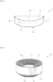
- FIG. 1 is a front view for generally illustrating a battery container according to this embodiment.
- FIG. 2 is a plan view of the battery container, and
- FIG. 3 is a sectional view taken along the line A-A of FIG. 2 .
- a battery container 1 illustrated in FIG. 1 to FIG. 3 includes a can body 2 and a can lid 3, each being made of a metal.
- a peripheral edge portion of the can lid 3 is joined to a peripheral edge of an opening portion of the can body 2 formed in a bottomed cylindrical shape. In this manner, the battery container 1 is configured to enclose a battery element 10.
- FIG. 3 an illustration of the battery element 10 to be enclosed in the battery container 1 is omitted.
- the can body 2 and the can lid 3 be each formed of a metal plate that has been subjected to a surface treatment such as a nickel plating treatment, a tin plating treatment, or a zinc plating treatment as needed in consideration of corrosion resistance to an electrolyte included in the battery element 10.
- a metal plate for example, a metal plate of steel, tin-free steel, stainless steel, aluminum, an aluminum alloy, or other alloys, or a clad plate formed by laminating different kinds of metals can be used.
- the can body 2 and the can lid 3 can be each formed of the metal plate as described above to have a desired shape by, for example, pressing or draw and ironing (DI).
- the can body 2 and the can lid 3 may be formed of the same kind of metal plates or may be formed of different kinds of metal plates.
- the can lid 3 (or the can body 2) serving as a positive electrode be made of aluminum or an aluminum alloy
- the can body 2 (or the can lid 3) serving as a negative electrode be made of steel having been subjected to a surface-treatment, in particular, steel having been subjected to a surface treatment that includes a nickel plating treatment.
- the can body 2 is formed in a bottomed cylindrical shape including a bottom portion 21 and a side wall portion 22.
- the side wall portion 22 stands upward from a peripheral edge of the bottom portion 21.
- the bottom portion 21 is formed so as to include a curved surface that is outwardly convex.
- the bottom portion 21 When the bottom portion 21 is formed so as to include the curved surface described above, the bottom portion 21 may be formed in a spherical shape with a constant curvature radius, a non-spherical shape with a curvature radius changing depending on an area, or a truncated conical shape including a curved surface formed in a spherical shape or a non-spherical shape.
- the curvature radius of the curved surface depends on the kind of or a plate thickness of a metal plate to be used, and is preferably from 35 mm to 300 mm, more preferably from 50 mm to 100 mm.
- the bottom portion 21 may be formed so as to include a curved surface that is inwardly convex.
- a recess portion that is set back inward can be formed in a part of the bottom portion 21 by, for example, forming a predetermined range of a central part of the bottom portion 21 into a flat shape or forming the bottom portion 21 with a recessed bottom shape 21a in consideration of stability at the time of placement of the battery container 1 with the bottom portion 21 facing down.
- the can lid 3 is formed so as to include a curved surface that is inwardly convex and is curved in the same manner as an area of the bottom portion 21 of the can body 2, which is formed as the curved surface.
- the phrase "curved in the same manner" is to be understood as follows.
- An area of the can lid 3 that is formed as the curved surface and the area of the bottom portion 21 of the can body 2 that is formed as the curved surface are not required to be curved in a completely identical manner.
- the area of the can lid 3 that is formed as the curved surface is only required to be curved so that a distance S between the can lid 3 and the area of the bottom portion 21 of the can body 2 that is formed as the curved surface is substantially the same within a range of machining accuracy under a state in which the can lid 3 is joined to the can body 2.
- a central part 3a of the can lid 3 may be formed in a flat shape.
- the can lid 3 may be formed so as to include a curved surface that is outwardly convex, although not particularly illustrated.
- the battery element 10 can be manufactured, for example, as follows.
- a positive electrode material 11, a negative electrode material 12, and separators 13 are each formed in an elongated band-like shape.
- the positive electrode material 11 includes a positive electrode current collector and a positive electrode active material layered thereon.
- the negative electrode material 12 includes a negative electrode current collector and a negative electrode active material layered thereon.
- the separator 13 is impregnated with an electrolyte. Then, the above-mentioned materials are placed in a winding machine.
- the separator 13, the negative electrode material 12, the separator 13, and the positive electrode material 11 are overlaid in the stated order and then are wound around a winding core.
- FIG. 4 a part of a terminal end of the battery element 10 that has been wound up is cut away.
- the separator 13, the positive electrode material 11, the separator 13, and the negative electrode material 12 may be overlaid in the stated order so as to form the battery element 10.
- the positive electrode material 11, the negative electrode material 12, and the separators 13 are generally formed with an equal width.
- the separators 13 are overlaid while both ends in a width direction are aligned with each other.
- the positive electrode material 11 is shifted to one end side in the width direction by several mm with respect to the separators 13, and the negative electrode material 12 is shifted to another end side in the width direction by several mm with respect to the separators 13.
- the positive electrode material 11, the negative electrode material 12, and the separators 13 are wound up.
- the negative electrode material 12 protrudes to one winding end surface (lower winding end surface in FIG. 4 ) side of the battery element 10 and the positive electrode material 11 protrudes to another winding end surface (upper winding end surface in FIG. 4 ) side of the battery element 10 while the positive electrode material 11 and the negative electrode material 12 are kept separated by the separators 13.
- the positive electrode material 11, the negative electrode material 12, and the separators 13 are being wound in the above-mentioned manner, the positive electrode material 11, the negative electrode material 12, and the separators 13 are gradually shifted to one side of the winding core in an axial direction (that is, a shift during winding is intentionally controlled).
- the positive electrode material 11, the negative electrode material 12, and the separators 13 are wound so that one winding end surface of the battery element 10 is curved correspondingly to the curved surface of the bottom portion 21 of the can body 2 and another winding end surface of the battery element 10 is curved correspondingly to the curved surface of the can lid 3.
- a central portion 10a which is formed after the winding core is removed, is hollow.
- the battery element 10 manufactured as described above is housed in the can body 2. After an appropriate amount of electrolyte is injected thereinto so that the separators 13 are impregnated with the electrolyte, the can lid 3 is joined to the can body 2 to thereby enclose the battery element 10 in the battery container 1.
- an end edge 12a of the negative electrode material 12 which protrudes to one winding end surface side of the battery element 10, is bent and is crimped to the bottom portion 21 of the can body 2 along its inclination.
- an end edge 11a of the positive electrode material 11, which protrudes to another winding end surface side of the battery element 10 is bent and is crimped to the can lid 3 along its inclination.
- the distance S between the can lid 3 and the bottom portion 21 of the can body 2 is appropriately adjusted in accordance with a thickness of the battery element 10 (distance between the winding end surfaces) (see FIG. 10(b) ).
- the negative electrode material 12 which protrudes to the one winding end surface side
- the positive electrode material 11 which protrudes to another winding end surface side
- a battery with the can body 2 side serving as a negative electrode and the can lid 3 side serving as a positive electrode is constructed.
- the positive electrode current collector, the negative electrode current collector, the positive electrode active material, the negative electrode active material, the electrolyte, and the separator, which form the battery element 10, can be appropriately selected from those used for this kind of battery. It is apparent that a winding method used at the time of manufacture of the battery element 10 can be changed as needed so that the can body 2 side serves as the positive electrode and the can lid 3 side serves as the negative electrode.
- the battery element 10 illustrated as one example in FIG. 4 is enclosed in the battery container 1 in the above-mentioned manner so that the battery having the can body 2 side serving as the negative electrode and the can lid 3 side serving as the positive electrode is constructed, it is required that the can body 2 and the can lid 3 be jointed together in a state of being electrically isolated from each other.
- insulating layers 20 and 30 be formed using an insulative resin material such as an epoxy resin, a silicone resin, an urethan resin, a phenol resin, polyethylene, or polypropylene on portions which are brought into contact with each other when the can body 2 and the can lid 3 are joined together (see FIG. 6 and FIG. 7 ).
- An insulating film made of, for example, the resin materials described above may be interposed at a joint portion between the can body 2 and the can lid 3 so that the can body 2 and the can lid 3 are joined together in an electrically isolated state.
- the can body 2 may be formed so that a flange portion 23 that extends outwards is formed at a peripheral edge portion of an opening of the can body 2.
- the can lid 3 may be formed so that a curled portion 31 is formed at the peripheral edge portion of the can lid 3.
- the curled portion 31 is shaped in such a manner as to cover the flange portion 23 formed at the can body 2 from above. It is preferred that the can body 2 and the can lid 3 be joined together so as to form a double seam.
- the double seam is formed by joining the flange portion 23 of the can body 2 and the curled portion 31 of the can lid 3 together by seaming as illustrated in FIG. 6 so as to cramp the flange portion 23 and the curled portion 31 each being in a double-folded state.
- FIG. 5 longitudinal cross sections of the can body 2 and the can lid 3 before being joined together are illustrated.
- FIG. 6 is an explanatory view for illustrating one example of a double seaming step.
- first seaming is first performed with use of a first seaming roll (not shown) under a state in which the curled portion 31 of the can lid 3 is placed on the flange portion 23 of the can body 2 in such a manner as to cover the flange portion 23 (see FIG. 6(a) ).
- first seaming roll not shown
- the flange portion 23 of the can body 2 is folded back toward a radially inner side of the can body 2, while the curled portion 31 of the can lid 3 is rolled up under the folded part (see Fig. 6(b) ).
- second seaming is performed with use of a second seaming roll (not shown).
- the flange portion 23 of the can body 2 and the curled portion 31 of the can lid 3 are cramped together under a state in which the curled portion 31 is rolled up under the flange portion 23 that is folded back. In this manner, the double seaming is completed (see FIG. 6(c) ).
- an end surface of the flange portion 23 of the can body 2 may bit into the insulating layer 30 formed over the curled portion 31 of the can lid 3 or an end surface of the curled portion 31 of the can lid 3 may bit into the insulating layer 20 formed over the flange portion 23 of the can body 2 as indicated by the arrows in FIG. 6(b) .
- the insulating layer 30 or the insulating layer 20 may be broken.
- a folded-back portion 23a be formed at an end portion of the flange portion 23, that is, at an end portion of the peripheral edge portion of the opening of the can body 2.
- a folded-back portion 31a be formed at an end portion of the curled portion 31, that is, at an end portion of the peripheral edge portion of the can lid 3.
- the folded-back portions 23a and 31a can be formed in such a manner as to have their end portions rounded by a processing method also called "hemming". Hemming is a method of folding back the end portion of the flange portion 23 and the end portion of the curled portion 31 at 180 degrees and then pressing and flattening the end portions.
- FIG. 7 there is illustrated one example of the double seaming step.
- the folded-back portions 23a and 31a are formed at both of the end portion of the flange portion 23 of the can body 2 and the end portion of the curled portion 31 of the can lid 3 and are then joined together by seaming.
- the end portion of the flange portion 23 of the can body 2 and the end portion of the curled portion 31 of the can lid 3 are rounded as the folded-back portions 23a and 31a.
- the insulating layers 20 and 30 formed thereover can be effectively prevented from being broken at the time of double seaming.
- a fold-back direction may be opposite to that in the example illustrated in FIG. 7 .
- the insulating layers 20 and 30 be formed after the formation of the folded-back portions 23a and 31a so that the folded-back portions 23a and 31a are entirely covered with the insulating layers 20 and 30 without leaving the folded-back end surface of the flange portion 23 and the folded-back end surface of the curled portion 31 exposed.
- a sealing compound, an anaerobic adhesive, or the like may be applied onto the joint portion between the can body 2 and the can lid 3 for the purpose of, for example, enhancing hermeticity or increasing joint strength.
- the bottom portion 21 of the can body 2 is formed so as to include the curved surface that is outwardly convex or inwardly convex.
- the can lid 3 is formed so as to include the curved surface that is inwardly convex or outwardly convex and is curved in the same manner as the area of the bottom portion 21 of the can body 2 that is formed as the curved surface.
- the battery container 1 can be used particularly suitably for the purpose of constructing a battery in which the battery element 10 illustrated as one example in FIG. 4 is enclosed.
- a battery is constructed as described above by electrically connecting the negative electrode material 12 protruding to one winding end surface side of the battery element 10 enclosed therein and the can body 2 to each other and electrically connecting the positive electrode material 11 protruding to another winding end surface side and the can lid 3 to each other.
- the battery described above when the bottom portion 21 of the can body 2 or the can lid 3 is deformed in a swelling manner due to a rise in internal pressure, electrical conduction efficiency between the negative electrode material 12 and the can body 2 may decrease or electrical conduction efficiency between the positive electrode material 11 and the can lid 3 may decrease. According to this embodiment, however, such a problem can be effectively prevented.
- the battery container 1 when used to construct, for example, a battery with the can body 2 side serving as a negative electrode and the can lid 3 side serving as a positive electrode, a plurality of battery containers 1 can be stacked on one another so that the can lid 3 of one of the battery containers 1 and the bottom portion 21 of the can body 2 of another one of the battery containers 1 are in contact with each other and be used in a serially connected state.
- the bottom portion 21 is formed so as to include a curved surface that is outwardly convex, and the central part of the bottom portion 21 is formed in the recessed bottom shape 21a.
- An area of the can lid 3 that is opposed to the central part of the bottom portion 21 except for the joint portion is formed as a curved surface that is inwardly convex.
- the air gap defined between the battery containers 1 that are stacked on one another provides the following advantage. That is, it is preferred that a safety valve for releasing a pressure when a pressure in the container excessively rises be provided to the battery container 1.
- a safety valve for releasing a pressure when a pressure in the container excessively rises be provided to the battery container 1.
- a safety valve for example, a groove-shaped score portion may be engraved into the recess portion corresponding to the inner area of the portion formed in the recessed bottom shape 21a at the central part of the bottom portion 21. The score portion may be configured to be broken to release the pressure when the pressure in the container excessively rises.
- the can body 2 and the can lid 3 were each formed using a steel plate having a surface that had been subjected to a nickel-plating treatment (nickel-plated steel plate).
- the bottom portion 21 of the can body 2 was formed so as to include a curved surface that is outwardly convex, and the curved surface was formed as a spherical surface with a radius of 60 mm.
- a thickness of the bottom portion 21 was 0.200 mm.
- the can lid 3 was formed so as to include a curved surface that is inwardly convex, and the curved surface was formed as a spherical surface with a radius of 60 mm, which was similar to the spherical surface of the curved surface of the bottom portion 21 of the can body 2.
- a thickness of the can lid 3 was 0.300 mm.
- the battery container 1 formed by joining the can lid 3 to the can body 2 had a diameter of about 66 mm and a height of about 20 mm.
- the battery container 1 formed by joining the can lid 3 to the can body 2 was installed horizontally, and a hose connected to an air compressor was hermetically connected to the central part of the bottom portion 21 of the can body 2. Displacement ⁇ [mm] of the central part of the can lid 3 in the vertical direction with respect to an internal pressure P [MPa] of the battery container 1 was measured. A result of the measurement is shown in FIG. 8 .
- the battery container 1 formed by joining the can lid 3 to the can body 2 was installed horizontally, and the hose connected to the air compressor was hermetically connected to the central part of the can lid 3. Displacement ⁇ [mm] of the central part of the bottom portion 21 in the vertical direction with respect to an internal pressure P [MPa] of the battery container 1 was measured. A result of the measurement is shown in FIG. 9 .
- the internal pressure P was increased until the can lid 3 started separating from the joint portion between the can body 2 and the can lid 3 and being folded over (until occurrence of buckling of the can lid 3). Then, the joint portion withstood up to 1.88 MPa.
- a can body and a can lid were formed in the same manner as that for those of Example 1 except that a bottom portion of the can body was formed in a flat shape and an area of the can lid except for a joint portion was formed in a flat shape.
- the can body and the can lid formed in such a manner were joined together by double seaming.
- Displacement ⁇ [mm] of a central part of the can lid in the vertical direction with respect to the internal pressure P [MPa] was measured in the same manner as that for Example 1. A result of the measurement is shown in FIG. 8 .
- Displacement ⁇ [mm] of a central part of the bottom portion in the vertical direction with respect to the internal pressure P [MPa] was measured in the same manner as that for Example 1. A result of the measurement is shown in FIG. 9 .
- the internal pressure P was increased in the same manner as that for Example 1 until buckling of the can lid occurred.
- the buckling of the can lid was observed at 0.59 MPa.
- the battery container 1 having a circular shape in plan view has been illustrated and described in the embodiment described above.
- the battery container 1 may have a polygonal shape such as a quadrangular shape in plan view as needed.
- a battery element to be enclosed in the battery container 1 is not limited to the example illustrated in FIG. 4 .
- a battery element to be enclosed may be formed as follows.
- the positive electrode material 11, the negative electrode material 12, and the separators 13, each being formed with an equal width, are wound in an overlaid state while two ends in the width direction of the positive electrode material 11, the negative electrode material 12, and the separators 13 are aligned with each other, respectively.
- a tab connected to the positive electrode material 11 and a tab connected to the negative electrode material 12 are drawn out to an outside of the battery container 1 so as to serve as a positive electrode terminal or a negative electrode terminal.
- a battery with the can lid 3 (or the can body 2) side serving as a positive electrode and the can body 2 (or the can lid 3) side serving as a negative electrode may be constructed by connecting the tab connected to the positive electrode material 11 and the tab connected to the negative electrode material 12 to the can lid 3 (or the can body 2) and the can body 2 (or the can lid 3), respectively.
- Such an aspect is applicable to the battery element 10 illustrated as one example in FIG. 4 .
- a conducting state between the battery container 1 and the battery element 10 can be improved.
Landscapes
- Chemical & Material Sciences (AREA)
- Chemical Kinetics & Catalysis (AREA)
- Electrochemistry (AREA)
- General Chemical & Material Sciences (AREA)
- Inorganic Chemistry (AREA)
- Engineering & Computer Science (AREA)
- Manufacturing & Machinery (AREA)
- Sealing Battery Cases Or Jackets (AREA)
- Secondary Cells (AREA)
Abstract
Description
- The present invention relates to a battery container in which a battery element is to be enclosed.
- A secondary battery as represented by a lithium-ion battery generally has a structure in which a battery element is enclosed in various containers. The battery element includes a positive electrode material, a negative electrode material, and a separator. The positive electrode material includes a positive electrode current collector and a positive electrode active material layered thereon. The negative electrode material includes a negative electrode current collector and a negative electrode active material layered thereon. The separator is impregnated with an electrolyte.
- For example, in
Patent Literature 1, there is disclosed a battery including two exterior materials that are bonded to each other at joint portions. Each of the exterior materials includes a stainless-steel plate and a resin layer formed thereon. The battery is formed by enclosing a battery element inside housing portions formed on the exterior materials. - [PTL 1]
JP 2012-94374 A - When this kind of battery is charged and discharged, a pressure in a container may increase due to, for example, a temperature rise or generation of gas from the battery element. In such a case, deformation of the container, which may be caused by an increase in internal pressure, is undesirable.
- The inventors of the present invention have conducted extensive studies in view of the circumstances described above so as to provide a battery container that is less deformable even when an internal pressure increases. As a result, the inventors achieved the present invention.
- According to the present invention, there is provided a battery container including a can body and a can lid, each being made of a metal, wherein a peripheral edge portion of the can lid is joined to a peripheral edge portion of an opening of the can body formed in a bottomed cylindrical shape, wherein a bottom portion of the can body is formed so as to include a curved surface that is outwardly convex or inwardly convex, and wherein the can lid is formed so as to include a curved surface that is inwardly convex or outwardly convex and is curved in the same manner as an area of the bottom portion that is formed as the curved surface.
- According to the present invention, the battery container that is less deformable even when the internal pressure increases can be provided.
-
-
FIG. 1 is a front view for generally illustrating a battery container according to an embodiment of the present invention. -
FIG. 2 is a plan view for generally illustrating the battery container according to the embodiment of the present invention. -
FIG. 3 is a sectional view taken along the line A-A ofFIG. 2 . -
FIG. 4 is an explanatory view for schematically illustrating one example of a battery element. -
FIG. 5 is an explanatory view for illustrating one example of a can body and a can lid before being joined together. -
FIG. 6 is an explanatory view for illustrating one example of a double seaming step. -
FIG. 7 is an explanatory view for illustrating another example of the double seaming step. -
FIG. 8 is a graph for showing displacement δ [mm] of a central part of the can lid in a vertical direction with respect to an internal pressure P [MPa] of the battery container. -
FIG. 9 is a graph for showing displacement δ [mm] of a central part of a bottom portion in the vertical direction with respect to the internal pressure P [MPa] of the battery container. -
FIG. 10 is an explanatory view for schematically illustrating a part of a cross section of the battery container and the battery element for one example of a contact state therebetween. - Now, a preferred embodiment of the present invention is described with reference to the drawings.
-
FIG. 1 is a front view for generally illustrating a battery container according to this embodiment.FIG. 2 is a plan view of the battery container, andFIG. 3 is a sectional view taken along the line A-A ofFIG. 2 . - A
battery container 1 illustrated inFIG. 1 to FIG. 3 includes acan body 2 and acan lid 3, each being made of a metal. A peripheral edge portion of thecan lid 3 is joined to a peripheral edge of an opening portion of thecan body 2 formed in a bottomed cylindrical shape. In this manner, thebattery container 1 is configured to enclose abattery element 10. - In
FIG. 3 , an illustration of thebattery element 10 to be enclosed in thebattery container 1 is omitted. - While details of the
battery element 10 are described later, it is preferred that thecan body 2 and the canlid 3 be each formed of a metal plate that has been subjected to a surface treatment such as a nickel plating treatment, a tin plating treatment, or a zinc plating treatment as needed in consideration of corrosion resistance to an electrolyte included in thebattery element 10. As the metal plate, for example, a metal plate of steel, tin-free steel, stainless steel, aluminum, an aluminum alloy, or other alloys, or a clad plate formed by laminating different kinds of metals can be used. Thecan body 2 and thecan lid 3 can be each formed of the metal plate as described above to have a desired shape by, for example, pressing or draw and ironing (DI). Thecan body 2 and thecan lid 3 may be formed of the same kind of metal plates or may be formed of different kinds of metal plates. When different kinds of metal plates are used, it is preferred that, in a lithium-ion battery, for example, the can lid 3 (or the can body 2) serving as a positive electrode be made of aluminum or an aluminum alloy and the can body 2 (or the can lid 3) serving as a negative electrode be made of steel having been subjected to a surface-treatment, in particular, steel having been subjected to a surface treatment that includes a nickel plating treatment. - In the illustrated example, the
can body 2 is formed in a bottomed cylindrical shape including abottom portion 21 and aside wall portion 22. Theside wall portion 22 stands upward from a peripheral edge of thebottom portion 21. Thebottom portion 21 is formed so as to include a curved surface that is outwardly convex. - When the
bottom portion 21 is formed so as to include the curved surface described above, thebottom portion 21 may be formed in a spherical shape with a constant curvature radius, a non-spherical shape with a curvature radius changing depending on an area, or a truncated conical shape including a curved surface formed in a spherical shape or a non-spherical shape. The curvature radius of the curved surface depends on the kind of or a plate thickness of a metal plate to be used, and is preferably from 35 mm to 300 mm, more preferably from 50 mm to 100 mm. Although not particularly illustrated, thebottom portion 21 may be formed so as to include a curved surface that is inwardly convex. - Further, when the
bottom portion 21 is formed so as to include a curved surface that is outwardly convex, a recess portion that is set back inward can be formed in a part of thebottom portion 21 by, for example, forming a predetermined range of a central part of thebottom portion 21 into a flat shape or forming thebottom portion 21 with a recessedbottom shape 21a in consideration of stability at the time of placement of thebattery container 1 with thebottom portion 21 facing down. - Meanwhile, the
can lid 3 is formed so as to include a curved surface that is inwardly convex and is curved in the same manner as an area of thebottom portion 21 of thecan body 2, which is formed as the curved surface. - In this case, the phrase "curved in the same manner" is to be understood as follows. An area of the
can lid 3 that is formed as the curved surface and the area of thebottom portion 21 of thecan body 2 that is formed as the curved surface are not required to be curved in a completely identical manner. The area of thecan lid 3 that is formed as the curved surface is only required to be curved so that a distance S between thecan lid 3 and the area of thebottom portion 21 of thecan body 2 that is formed as the curved surface is substantially the same within a range of machining accuracy under a state in which thecan lid 3 is joined to thecan body 2. - Further, as illustrated, a
central part 3a of thecan lid 3 may be formed in a flat shape. When thebottom portion 21 is formed so as to include a curved surface that is inwardly convex, thecan lid 3 may be formed so as to include a curved surface that is outwardly convex, although not particularly illustrated. - Next, one example of the
battery element 10 to be enclosed in thebattery container 1 is described. - In
FIG. 4 , one example of thebattery element 10 is schematically illustrated. Thebattery element 10 can be manufactured, for example, as follows. Apositive electrode material 11, anegative electrode material 12, andseparators 13 are each formed in an elongated band-like shape. Thepositive electrode material 11 includes a positive electrode current collector and a positive electrode active material layered thereon. Thenegative electrode material 12 includes a negative electrode current collector and a negative electrode active material layered thereon. Theseparator 13 is impregnated with an electrolyte. Then, the above-mentioned materials are placed in a winding machine. Theseparator 13, thenegative electrode material 12, theseparator 13, and thepositive electrode material 11 are overlaid in the stated order and then are wound around a winding core. - In
FIG. 4 , a part of a terminal end of thebattery element 10 that has been wound up is cut away. Theseparator 13, thepositive electrode material 11, theseparator 13, and thenegative electrode material 12 may be overlaid in the stated order so as to form thebattery element 10. - The
positive electrode material 11, thenegative electrode material 12, and theseparators 13 are generally formed with an equal width. In one example of thebattery element 10 illustrated inFIG. 4 , theseparators 13 are overlaid while both ends in a width direction are aligned with each other. Thepositive electrode material 11 is shifted to one end side in the width direction by several mm with respect to theseparators 13, and thenegative electrode material 12 is shifted to another end side in the width direction by several mm with respect to theseparators 13. Under the above-mentioned state, thepositive electrode material 11, thenegative electrode material 12, and theseparators 13 are wound up. In this manner, thenegative electrode material 12 protrudes to one winding end surface (lower winding end surface inFIG. 4 ) side of thebattery element 10 and thepositive electrode material 11 protrudes to another winding end surface (upper winding end surface inFIG. 4 ) side of thebattery element 10 while thepositive electrode material 11 and thenegative electrode material 12 are kept separated by theseparators 13. - Then, while the
positive electrode material 11, thenegative electrode material 12, and theseparators 13 are being wound in the above-mentioned manner, thepositive electrode material 11, thenegative electrode material 12, and theseparators 13 are gradually shifted to one side of the winding core in an axial direction (that is, a shift during winding is intentionally controlled). As a result, thepositive electrode material 11, thenegative electrode material 12, and theseparators 13 are wound so that one winding end surface of thebattery element 10 is curved correspondingly to the curved surface of thebottom portion 21 of thecan body 2 and another winding end surface of thebattery element 10 is curved correspondingly to the curved surface of thecan lid 3. - In one example of the
battery element 10 illustrated inFIG. 4 , acentral portion 10a, which is formed after the winding core is removed, is hollow. - The
battery element 10 manufactured as described above is housed in thecan body 2. After an appropriate amount of electrolyte is injected thereinto so that theseparators 13 are impregnated with the electrolyte, thecan lid 3 is joined to thecan body 2 to thereby enclose thebattery element 10 in thebattery container 1. At this time, as partially illustrated inFIG. 10 , anend edge 12a of thenegative electrode material 12, which protrudes to one winding end surface side of thebattery element 10, is bent and is crimped to thebottom portion 21 of thecan body 2 along its inclination. At the same time, anend edge 11a of thepositive electrode material 11, which protrudes to another winding end surface side of thebattery element 10, is bent and is crimped to thecan lid 3 along its inclination. Under the above-mentioned state, dimensions of the portions and the like are appropriately adjusted so that thebattery element 10 is fixed inside thebattery container 1. In particular, the distance S between thecan lid 3 and thebottom portion 21 of thecan body 2 is appropriately adjusted in accordance with a thickness of the battery element 10 (distance between the winding end surfaces) (seeFIG. 10(b) ). When thebattery element 10 illustrated inFIG. 4 as one example is enclosed in thebattery container 1 in the above-mentioned manner, thenegative electrode material 12, which protrudes to the one winding end surface side, is electrically connected to thecan body 2 over a sufficient conduction area and thepositive electrode material 11, which protrudes to another winding end surface side, is electrically connected to thecan lid 3 over a sufficient conduction area. As a result, a battery with thecan body 2 side serving as a negative electrode and thecan lid 3 side serving as a positive electrode is constructed. - The positive electrode current collector, the negative electrode current collector, the positive electrode active material, the negative electrode active material, the electrolyte, and the separator, which form the
battery element 10, can be appropriately selected from those used for this kind of battery. It is apparent that a winding method used at the time of manufacture of thebattery element 10 can be changed as needed so that thecan body 2 side serves as the positive electrode and thecan lid 3 side serves as the negative electrode. - Next, a joint structure for joining the
can lid 3 to thecan body 2 is described. - When the
battery element 10 illustrated as one example inFIG. 4 is enclosed in thebattery container 1 in the above-mentioned manner so that the battery having thecan body 2 side serving as the negative electrode and thecan lid 3 side serving as the positive electrode is constructed, it is required that thecan body 2 and thecan lid 3 be jointed together in a state of being electrically isolated from each other. - In such a case, it is preferred that insulating
layers can body 2 and thecan lid 3 are joined together (seeFIG. 6 andFIG. 7 ). An insulating film made of, for example, the resin materials described above may be interposed at a joint portion between thecan body 2 and thecan lid 3 so that thecan body 2 and thecan lid 3 are joined together in an electrically isolated state. - Further, as in
FIG. 5 in which one example of thecan body 2 and thecan lid 3 before being joined together is illustrated, thecan body 2 may be formed so that aflange portion 23 that extends outwards is formed at a peripheral edge portion of an opening of thecan body 2. Meanwhile, thecan lid 3 may be formed so that a curledportion 31 is formed at the peripheral edge portion of thecan lid 3. The curledportion 31 is shaped in such a manner as to cover theflange portion 23 formed at thecan body 2 from above. It is preferred that thecan body 2 and thecan lid 3 be joined together so as to form a double seam. The double seam is formed by joining theflange portion 23 of thecan body 2 and the curledportion 31 of thecan lid 3 together by seaming as illustrated inFIG. 6 so as to cramp theflange portion 23 and the curledportion 31 each being in a double-folded state. - In
FIG. 5 , longitudinal cross sections of thecan body 2 and thecan lid 3 before being joined together are illustrated. -
FIG. 6 is an explanatory view for illustrating one example of a double seaming step. In order to join theflange portion 23 of thecan body 2 and the curledportion 31 of thecan lid 3 together by seaming, first seaming is first performed with use of a first seaming roll (not shown) under a state in which the curledportion 31 of thecan lid 3 is placed on theflange portion 23 of thecan body 2 in such a manner as to cover the flange portion 23 (seeFIG. 6(a) ). At this time, theflange portion 23 of thecan body 2 is folded back toward a radially inner side of thecan body 2, while the curledportion 31 of thecan lid 3 is rolled up under the folded part (seeFig. 6(b) ). Subsequently, second seaming is performed with use of a second seaming roll (not shown). Theflange portion 23 of thecan body 2 and the curledportion 31 of thecan lid 3 are cramped together under a state in which the curledportion 31 is rolled up under theflange portion 23 that is folded back. In this manner, the double seaming is completed (seeFIG. 6(c) ). - Further, when the
flange portion 23 of thecan body 2 and the curledportion 31 of thecan lid 3 are joined together by seaming as in one example illustrated inFIG. 6 , an end surface of theflange portion 23 of thecan body 2 may bit into the insulatinglayer 30 formed over the curledportion 31 of thecan lid 3 or an end surface of the curledportion 31 of thecan lid 3 may bit into the insulatinglayer 20 formed over theflange portion 23 of thecan body 2 as indicated by the arrows inFIG. 6(b) . Thus, there is a concern that the insulatinglayer 30 or the insulatinglayer 20 may be broken. - When there is a concern about the problem described above, for example, when the insulating
layer 30 formed over the curledportion 31 of thecan lid 3 may be broken by the end surface of theflange portion 23 of thecan body 2, it is preferred that a folded-back portion 23a be formed at an end portion of theflange portion 23, that is, at an end portion of the peripheral edge portion of the opening of thecan body 2. When there is a concern that the insulatinglayer 20 formed over theflange portion 23 of thecan body 2 may be broken by the end surface of the curledportion 31 of thecan lid 3, it is preferred that a folded-back portion 31a be formed at an end portion of the curledportion 31, that is, at an end portion of the peripheral edge portion of thecan lid 3. The folded-back portions flange portion 23 and the end portion of the curledportion 31 at 180 degrees and then pressing and flattening the end portions. - In
FIG. 7 , there is illustrated one example of the double seaming step. In this example of the double seaming step, the folded-back portions flange portion 23 of thecan body 2 and the end portion of the curledportion 31 of thecan lid 3 and are then joined together by seaming. In the example described above, the end portion of theflange portion 23 of thecan body 2 and the end portion of the curledportion 31 of thecan lid 3 are rounded as the folded-back portions layers - As described above, when the folded-
back portion can body 2 or the end portion of the peripheral edge portion of thecan lid 3 as needed, the insulatinglayers back portion FIG. 7 . - When the folded-
back portions layers back portions back portions layers flange portion 23 and the folded-back end surface of the curledportion 31 exposed. - A sealing compound, an anaerobic adhesive, or the like may be applied onto the joint portion between the
can body 2 and thecan lid 3 for the purpose of, for example, enhancing hermeticity or increasing joint strength. - According to this embodiment described above, the
bottom portion 21 of thecan body 2 is formed so as to include the curved surface that is outwardly convex or inwardly convex. At the same time, thecan lid 3 is formed so as to include the curved surface that is inwardly convex or outwardly convex and is curved in the same manner as the area of thebottom portion 21 of thecan body 2 that is formed as the curved surface. As a result, thebattery container 1, which is less deformable even when an internal pressure rises, can be provided. - Further, the
battery container 1 according to this embodiment can be used particularly suitably for the purpose of constructing a battery in which thebattery element 10 illustrated as one example inFIG. 4 is enclosed. For example, a battery is constructed as described above by electrically connecting thenegative electrode material 12 protruding to one winding end surface side of thebattery element 10 enclosed therein and thecan body 2 to each other and electrically connecting thepositive electrode material 11 protruding to another winding end surface side and thecan lid 3 to each other. In the battery described above, when thebottom portion 21 of thecan body 2 or thecan lid 3 is deformed in a swelling manner due to a rise in internal pressure, electrical conduction efficiency between thenegative electrode material 12 and thecan body 2 may decrease or electrical conduction efficiency between thepositive electrode material 11 and thecan lid 3 may decrease. According to this embodiment, however, such a problem can be effectively prevented. - Further, when the
battery container 1 according to this embodiment is used to construct, for example, a battery with thecan body 2 side serving as a negative electrode and thecan lid 3 side serving as a positive electrode, a plurality ofbattery containers 1 can be stacked on one another so that thecan lid 3 of one of thebattery containers 1 and thebottom portion 21 of thecan body 2 of another one of thebattery containers 1 are in contact with each other and be used in a serially connected state. In such a case, thebottom portion 21 is formed so as to include a curved surface that is outwardly convex, and the central part of thebottom portion 21 is formed in the recessedbottom shape 21a. An area of thecan lid 3 that is opposed to the central part of thebottom portion 21 except for the joint portion is formed as a curved surface that is inwardly convex. As a result, an air gap can be defined between thecan lid 3 of one of thebattery containers 1 that are stacked on one another and the area of thebottom portion 21 of another one of thebattery containers 1 that is formed in the recessedbottom shape 21a. - The air gap defined between the
battery containers 1 that are stacked on one another provides the following advantage. That is, it is preferred that a safety valve for releasing a pressure when a pressure in the container excessively rises be provided to thebattery container 1. When such a safety valve is provided in a recess portion corresponding to an inner area of the portion formed in the recessedbottom shape 21a at the central part of thebottom portion 21, an excessively increased internal pressure can be effectively released via the air gap without hindering an operation of the safety valve. As the safety valve, for example, a groove-shaped score portion may be engraved into the recess portion corresponding to the inner area of the portion formed in the recessedbottom shape 21a at the central part of thebottom portion 21. The score portion may be configured to be broken to release the pressure when the pressure in the container excessively rises. - Hereinafter, the present invention is described in more detail by way of specific examples.
- The
can body 2 and thecan lid 3 were each formed using a steel plate having a surface that had been subjected to a nickel-plating treatment (nickel-plated steel plate). Thebottom portion 21 of thecan body 2 was formed so as to include a curved surface that is outwardly convex, and the curved surface was formed as a spherical surface with a radius of 60 mm. A thickness of thebottom portion 21 was 0.200 mm. Thecan lid 3 was formed so as to include a curved surface that is inwardly convex, and the curved surface was formed as a spherical surface with a radius of 60 mm, which was similar to the spherical surface of the curved surface of thebottom portion 21 of thecan body 2. A thickness of thecan lid 3 was 0.300 mm. - Subsequently, the peripheral edge portion of the
can lid 3 was joined to the peripheral edge portion of the opening of thecan body 2 by double seaming. Thebattery container 1 formed by joining thecan lid 3 to thecan body 2 had a diameter of about 66 mm and a height of about 20 mm. - The
battery container 1 formed by joining thecan lid 3 to thecan body 2 was installed horizontally, and a hose connected to an air compressor was hermetically connected to the central part of thebottom portion 21 of thecan body 2. Displacement δ [mm] of the central part of thecan lid 3 in the vertical direction with respect to an internal pressure P [MPa] of thebattery container 1 was measured. A result of the measurement is shown inFIG. 8 . - Similarly, the
battery container 1 formed by joining thecan lid 3 to thecan body 2 was installed horizontally, and the hose connected to the air compressor was hermetically connected to the central part of thecan lid 3. Displacement δ [mm] of the central part of thebottom portion 21 in the vertical direction with respect to an internal pressure P [MPa] of thebattery container 1 was measured. A result of the measurement is shown inFIG. 9 . - Further, the internal pressure P was increased until the
can lid 3 started separating from the joint portion between thecan body 2 and thecan lid 3 and being folded over (until occurrence of buckling of the can lid 3). Then, the joint portion withstood up to 1.88 MPa. - A can body and a can lid were formed in the same manner as that for those of Example 1 except that a bottom portion of the can body was formed in a flat shape and an area of the can lid except for a joint portion was formed in a flat shape. The can body and the can lid formed in such a manner were joined together by double seaming.
- Displacement δ [mm] of a central part of the can lid in the vertical direction with respect to the internal pressure P [MPa] was measured in the same manner as that for Example 1. A result of the measurement is shown in
FIG. 8 . - Displacement δ [mm] of a central part of the bottom portion in the vertical direction with respect to the internal pressure P [MPa] was measured in the same manner as that for Example 1. A result of the measurement is shown in
FIG. 9 . - The internal pressure P was increased in the same manner as that for Example 1 until buckling of the can lid occurred. The buckling of the can lid was observed at 0.59 MPa.
- The preferred embodiment of the present invention has been described above, but the present invention is not limited to the embodiment described above. Needless to say, various modifications may be made within the scope of the present invention.
- For example, an example of the
battery container 1 having a circular shape in plan view has been illustrated and described in the embodiment described above. However, thebattery container 1 may have a polygonal shape such as a quadrangular shape in plan view as needed. - Further, the
battery element 10 to be enclosed in thebattery container 1 is not limited to the example illustrated inFIG. 4 . For example, a battery element to be enclosed may be formed as follows. Thepositive electrode material 11, thenegative electrode material 12, and theseparators 13, each being formed with an equal width, are wound in an overlaid state while two ends in the width direction of thepositive electrode material 11, thenegative electrode material 12, and theseparators 13 are aligned with each other, respectively. A tab connected to thepositive electrode material 11 and a tab connected to thenegative electrode material 12 are drawn out to an outside of thebattery container 1 so as to serve as a positive electrode terminal or a negative electrode terminal. When the battery element described above is enclosed, it is not required that thecan body 2 and thecan lid 3 be joined together in an electrically isolated state. Further, a battery with the can lid 3 (or the can body 2) side serving as a positive electrode and the can body 2 (or the can lid 3) side serving as a negative electrode may be constructed by connecting the tab connected to thepositive electrode material 11 and the tab connected to thenegative electrode material 12 to the can lid 3 (or the can body 2) and the can body 2 (or the can lid 3), respectively. Such an aspect is applicable to thebattery element 10 illustrated as one example inFIG. 4 . When both of conduction through the winding end surface of thebattery element 10 as described above and conduction through the tabs are used, a conducting state between thebattery container 1 and thebattery element 10 can be improved. -
- 1 battery container
- 2 can body
- 20 insulating layer
- 21 bottom portion
- 23 flange portion (peripheral edge portion of opening of can body)
- 23a folded-back portion
- 3 can lid
- 30 insulating layer
- 31 curled portion (peripheral edge portion of can lid)
- 31a folded-back portion
- 10 battery element
- 11 positive electrode material
- 12 negative electrode material
- 13 separator
Claims (5)
- A battery container, comprising a can body and a can lid, each being made of a metal,wherein a peripheral edge portion of the can lid is joined to a peripheral edge portion of an opening of the can body formed in a bottomed cylindrical shape,wherein a bottom portion of the can body is formed so as to include a curved surface that is outwardly convex or inwardly convex, andwherein the can lid is formed so as to include a curved surface that is inwardly convex or outwardly convex and is curved in the same manner as an area of the bottom portion that is formed as the curved surface.
- The battery container according to claim 1, wherein the can body and the can lid are joined together by double seaming.
- The battery container according to claim 2, wherein a folded-back portion is formed at at least one of an end portion of the peripheral edge portion of the opening of the can body or an end portion of the peripheral edge portion of the can lid.
- The battery container according to any one of claims 1 to 3, wherein the can body and the can lid are joined together in an electrically isolated state.
- The battery container according to claim 4,wherein the battery container is configured to enclose a battery element,wherein the battery element includes a positive electrode material, a negative electrode material, and separators being formed with an equal width and are overlaid in the order of the separator, the negative electrode material, the separator, and the positive electrode material or in the order of the separator, the positive electrode material, the separator, and the negative electrode material,wherein the positive electrode material, the negative electrode material, and the separators are wound while the positive electrode material is shifted to one end side in a width direction of the battery element and the negative electrode material is shifted to another end side in the width direction with respect to the separators that are overlaid with two ends in the width direction being both aligned with each other, andwherein one winding end surface is curved correspondingly to the curved surface of the can body, and another winding end surface is curved correspondingly to the curved surface of the can lid.
Applications Claiming Priority (2)
| Application Number | Priority Date | Filing Date | Title |
|---|---|---|---|
| JP2022058953A JP7340060B1 (en) | 2022-03-31 | 2022-03-31 | battery container |
| PCT/JP2023/006661 WO2023189066A1 (en) | 2022-03-31 | 2023-02-24 | Battery container |
Publications (2)
| Publication Number | Publication Date |
|---|---|
| EP4503275A1 true EP4503275A1 (en) | 2025-02-05 |
| EP4503275A4 EP4503275A4 (en) | 2026-04-15 |
Family
ID=87882071
Family Applications (1)
| Application Number | Title | Priority Date | Filing Date |
|---|---|---|---|
| EP23779096.9A Pending EP4503275A4 (en) | 2022-03-31 | 2023-02-24 | BATTERY CONTAINER |
Country Status (6)
| Country | Link |
|---|---|
| US (1) | US20250007054A1 (en) |
| EP (1) | EP4503275A4 (en) |
| JP (1) | JP7340060B1 (en) |
| KR (1) | KR20240168918A (en) |
| CN (1) | CN118489181A (en) |
| WO (1) | WO2023189066A1 (en) |
Family Cites Families (7)
| Publication number | Priority date | Publication date | Assignee | Title |
|---|---|---|---|---|
| JP2993069B2 (en) * | 1990-07-31 | 1999-12-20 | 新神戸電機株式会社 | Sealed battery pack |
| JP4035710B2 (en) * | 2002-06-06 | 2008-01-23 | 東芝電池株式会社 | Flat battery |
| DE102005058132A1 (en) * | 2005-11-30 | 2007-06-06 | Varta Microbattery Gmbh | Galvanic element with new housing |
| JP5374742B2 (en) | 2010-10-27 | 2013-12-25 | 日新製鋼株式会社 | Laminate battery exterior material, laminate battery exterior material manufacturing method, and laminate battery manufacturing method |
| JP6406836B2 (en) | 2014-03-13 | 2018-10-17 | Fdk株式会社 | Cylindrical battery manufacturing method and cylindrical battery |
| KR102984068B1 (en) * | 2020-03-18 | 2026-06-29 | 주하이 코스엠엑스 배터리 컴퍼니 리미티드 | Battery cases, batteries, and electronic devices |
| JP7494528B2 (en) | 2020-03-31 | 2024-06-04 | 東洋製罐グループホールディングス株式会社 | Double seaming structure and batteries and cans having the same |
-
2022
- 2022-03-31 JP JP2022058953A patent/JP7340060B1/en active Active
-
2023
- 2023-02-24 KR KR1020247021342A patent/KR20240168918A/en active Pending
- 2023-02-24 CN CN202380015866.7A patent/CN118489181A/en active Pending
- 2023-02-24 WO PCT/JP2023/006661 patent/WO2023189066A1/en not_active Ceased
- 2023-02-24 EP EP23779096.9A patent/EP4503275A4/en active Pending
-
2024
- 2024-09-13 US US18/884,543 patent/US20250007054A1/en active Pending
Also Published As
| Publication number | Publication date |
|---|---|
| CN118489181A (en) | 2024-08-13 |
| JP7340060B1 (en) | 2023-09-06 |
| US20250007054A1 (en) | 2025-01-02 |
| WO2023189066A1 (en) | 2023-10-05 |
| JP2023150060A (en) | 2023-10-16 |
| EP4503275A4 (en) | 2026-04-15 |
| KR20240168918A (en) | 2024-12-02 |
Similar Documents
| Publication | Publication Date | Title |
|---|---|---|
| US20250174702A1 (en) | Button cells and method of producing same | |
| EP2429010B1 (en) | Battery cell design and method of its construction | |
| US5665483A (en) | Sealed storage battery | |
| JP6731831B2 (en) | Electrochemical cell | |
| JP5715155B2 (en) | Cylindrical secondary battery | |
| US11171384B2 (en) | Secondary battery | |
| JP7656535B2 (en) | Cylindrical battery | |
| US10873060B2 (en) | Battery can for a battery | |
| EP4597656A1 (en) | Cylindrical secondary battery | |
| EP4372857A2 (en) | Cylindrical secondary battery | |
| EP4210157A1 (en) | Cylindrical secondary battery | |
| CN114600303A (en) | Pouch-type secondary battery, battery pack, and method of manufacturing pouch-type secondary battery | |
| CN115176378A (en) | Button type secondary battery | |
| EP4250440B1 (en) | Cylindrical battery | |
| US20120180308A1 (en) | Battery fabrication method | |
| JP7213213B2 (en) | Battery cell and manufacturing method thereof | |
| JP2009230991A (en) | Cylindrical cell and manufacturing method of cylindrical cell | |
| US20250007054A1 (en) | Battery container | |
| US7687196B2 (en) | Prismatic battery and method for manufacturing the same | |
| JP2025527822A (en) | Welded structure of battery can and cap and battery cell to which this is applied | |
| EP4117107A1 (en) | Battery | |
| EP4645563A1 (en) | Battery cell having structure for preventing side wall member of can from rupturing | |
| KR102833974B1 (en) | Battery cell for preventing side wall of battery can from rupturing | |
| EP4708474A1 (en) | Battery cell and battery module including the same | |
| KR20260030653A (en) | Electrochemical energy storage element |
Legal Events
| Date | Code | Title | Description |
|---|---|---|---|
| STAA | Information on the status of an ep patent application or granted ep patent |
Free format text: STATUS: THE INTERNATIONAL PUBLICATION HAS BEEN MADE |
|
| PUAI | Public reference made under article 153(3) epc to a published international application that has entered the european phase |
Free format text: ORIGINAL CODE: 0009012 |
|
| STAA | Information on the status of an ep patent application or granted ep patent |
Free format text: STATUS: REQUEST FOR EXAMINATION WAS MADE |
|
| 17P | Request for examination filed |
Effective date: 20240930 |
|
| AK | Designated contracting states |
Kind code of ref document: A1 Designated state(s): AL AT BE BG CH CY CZ DE DK EE ES FI FR GB GR HR HU IE IS IT LI LT LU LV MC ME MK MT NL NO PL PT RO RS SE SI SK SM TR |
|
| DAV | Request for validation of the european patent (deleted) | ||
| DAX | Request for extension of the european patent (deleted) | ||
| A4 | Supplementary search report drawn up and despatched |
Effective date: 20260312 |
|
| RIC1 | Information provided on ipc code assigned before grant |
Ipc: H01M 50/107 20210101AFI20260306BHEP Ipc: H01M 10/04 20060101ALI20260306BHEP Ipc: H01M 50/119 20210101ALI20260306BHEP Ipc: H01M 50/152 20210101ALI20260306BHEP Ipc: H01M 50/159 20210101ALI20260306BHEP Ipc: H01M 50/167 20210101ALI20260306BHEP Ipc: H01M 50/184 20210101ALI20260306BHEP Ipc: H01M 50/593 20210101ALI20260306BHEP Ipc: H01M 50/586 20210101ALI20260306BHEP Ipc: H01M 50/153 20210101ALI20260306BHEP Ipc: H01M 10/0587 20100101ALI20260306BHEP Ipc: H01M 50/109 20210101ALI20260306BHEP |