EP4503211A1 - Fuel cell start-up architecture - Google Patents
Fuel cell start-up architecture Download PDFInfo
- Publication number
- EP4503211A1 EP4503211A1 EP23461634.0A EP23461634A EP4503211A1 EP 4503211 A1 EP4503211 A1 EP 4503211A1 EP 23461634 A EP23461634 A EP 23461634A EP 4503211 A1 EP4503211 A1 EP 4503211A1
- Authority
- EP
- European Patent Office
- Prior art keywords
- hydrogen
- oxygen source
- fuel cell
- source
- architecture
- Prior art date
- Legal status (The legal status is an assumption and is not a legal conclusion. Google has not performed a legal analysis and makes no representation as to the accuracy of the status listed.)
- Pending
Links
Images

Classifications
-
- H—ELECTRICITY
- H01—ELECTRIC ELEMENTS
- H01M—PROCESSES OR MEANS, e.g. BATTERIES, FOR THE DIRECT CONVERSION OF CHEMICAL ENERGY INTO ELECTRICAL ENERGY
- H01M8/00—Fuel cells; Manufacture thereof
- H01M8/04—Auxiliary arrangements, e.g. for control of pressure or for circulation of fluids
- H01M8/04223—Auxiliary arrangements, e.g. for control of pressure or for circulation of fluids during start-up or shut-down; Depolarisation or activation, e.g. purging; Means for short-circuiting defective fuel cells
- H01M8/04225—Auxiliary arrangements, e.g. for control of pressure or for circulation of fluids during start-up or shut-down; Depolarisation or activation, e.g. purging; Means for short-circuiting defective fuel cells during start-up
-
- H—ELECTRICITY
- H01—ELECTRIC ELEMENTS
- H01M—PROCESSES OR MEANS, e.g. BATTERIES, FOR THE DIRECT CONVERSION OF CHEMICAL ENERGY INTO ELECTRICAL ENERGY
- H01M8/00—Fuel cells; Manufacture thereof
- H01M8/04—Auxiliary arrangements, e.g. for control of pressure or for circulation of fluids
- H01M8/04298—Processes for controlling fuel cells or fuel cell systems
- H01M8/043—Processes for controlling fuel cells or fuel cell systems applied during specific periods
- H01M8/04302—Processes for controlling fuel cells or fuel cell systems applied during specific periods applied during start-up
-
- B—PERFORMING OPERATIONS; TRANSPORTING
- B60—VEHICLES IN GENERAL
- B60L—PROPULSION OF ELECTRICALLY-PROPELLED VEHICLES; SUPPLYING ELECTRIC POWER FOR AUXILIARY EQUIPMENT OF ELECTRICALLY-PROPELLED VEHICLES; ELECTRODYNAMIC BRAKE SYSTEMS FOR VEHICLES IN GENERAL; MAGNETIC SUSPENSION OR LEVITATION FOR VEHICLES; MONITORING OPERATING VARIABLES OF ELECTRICALLY-PROPELLED VEHICLES; ELECTRIC SAFETY DEVICES FOR ELECTRICALLY-PROPELLED VEHICLES
- B60L58/00—Methods or circuit arrangements for monitoring or controlling batteries or fuel cells, specially adapted for electric vehicles
- B60L58/30—Methods or circuit arrangements for monitoring or controlling batteries or fuel cells, specially adapted for electric vehicles for monitoring or controlling fuel cells
- B60L58/31—Methods or circuit arrangements for monitoring or controlling batteries or fuel cells, specially adapted for electric vehicles for monitoring or controlling fuel cells for starting of fuel cells
-
- H—ELECTRICITY
- H01—ELECTRIC ELEMENTS
- H01M—PROCESSES OR MEANS, e.g. BATTERIES, FOR THE DIRECT CONVERSION OF CHEMICAL ENERGY INTO ELECTRICAL ENERGY
- H01M8/00—Fuel cells; Manufacture thereof
- H01M8/04—Auxiliary arrangements, e.g. for control of pressure or for circulation of fluids
- H01M8/04007—Auxiliary arrangements, e.g. for control of pressure or for circulation of fluids related to heat exchange
- H01M8/04014—Heat exchange using gaseous fluids; Heat exchange by combustion of reactants
-
- H—ELECTRICITY
- H01—ELECTRIC ELEMENTS
- H01M—PROCESSES OR MEANS, e.g. BATTERIES, FOR THE DIRECT CONVERSION OF CHEMICAL ENERGY INTO ELECTRICAL ENERGY
- H01M8/00—Fuel cells; Manufacture thereof
- H01M8/04—Auxiliary arrangements, e.g. for control of pressure or for circulation of fluids
- H01M8/04082—Arrangements for control of reactant parameters, e.g. pressure or concentration
- H01M8/04089—Arrangements for control of reactant parameters, e.g. pressure or concentration of gaseous reactants
- H01M8/04097—Arrangements for control of reactant parameters, e.g. pressure or concentration of gaseous reactants with recycling of the reactants
-
- H—ELECTRICITY
- H01—ELECTRIC ELEMENTS
- H01M—PROCESSES OR MEANS, e.g. BATTERIES, FOR THE DIRECT CONVERSION OF CHEMICAL ENERGY INTO ELECTRICAL ENERGY
- H01M8/00—Fuel cells; Manufacture thereof
- H01M8/04—Auxiliary arrangements, e.g. for control of pressure or for circulation of fluids
- H01M8/04082—Arrangements for control of reactant parameters, e.g. pressure or concentration
- H01M8/04089—Arrangements for control of reactant parameters, e.g. pressure or concentration of gaseous reactants
- H01M8/04111—Arrangements for control of reactant parameters, e.g. pressure or concentration of gaseous reactants using a compressor turbine assembly
-
- H—ELECTRICITY
- H01—ELECTRIC ELEMENTS
- H01M—PROCESSES OR MEANS, e.g. BATTERIES, FOR THE DIRECT CONVERSION OF CHEMICAL ENERGY INTO ELECTRICAL ENERGY
- H01M8/00—Fuel cells; Manufacture thereof
- H01M8/04—Auxiliary arrangements, e.g. for control of pressure or for circulation of fluids
- H01M8/04082—Arrangements for control of reactant parameters, e.g. pressure or concentration
- H01M8/04201—Reactant storage and supply, e.g. means for feeding, pipes
-
- H—ELECTRICITY
- H01—ELECTRIC ELEMENTS
- H01M—PROCESSES OR MEANS, e.g. BATTERIES, FOR THE DIRECT CONVERSION OF CHEMICAL ENERGY INTO ELECTRICAL ENERGY
- H01M8/00—Fuel cells; Manufacture thereof
- H01M8/04—Auxiliary arrangements, e.g. for control of pressure or for circulation of fluids
- H01M8/04298—Processes for controlling fuel cells or fuel cell systems
- H01M8/04694—Processes for controlling fuel cells or fuel cell systems characterised by variables to be controlled
- H01M8/04746—Pressure; Flow
- H01M8/04753—Pressure; Flow of fuel cell reactants
-
- H—ELECTRICITY
- H01—ELECTRIC ELEMENTS
- H01M—PROCESSES OR MEANS, e.g. BATTERIES, FOR THE DIRECT CONVERSION OF CHEMICAL ENERGY INTO ELECTRICAL ENERGY
- H01M2250/00—Fuel cells for particular applications; Specific features of fuel cell system
- H01M2250/20—Fuel cells in motive systems, e.g. vehicle, ship, plane
-
- H—ELECTRICITY
- H01—ELECTRIC ELEMENTS
- H01M—PROCESSES OR MEANS, e.g. BATTERIES, FOR THE DIRECT CONVERSION OF CHEMICAL ENERGY INTO ELECTRICAL ENERGY
- H01M8/00—Fuel cells; Manufacture thereof
- H01M8/04—Auxiliary arrangements, e.g. for control of pressure or for circulation of fluids
- H01M8/04223—Auxiliary arrangements, e.g. for control of pressure or for circulation of fluids during start-up or shut-down; Depolarisation or activation, e.g. purging; Means for short-circuiting defective fuel cells
- H01M8/04268—Heating of fuel cells during the start-up of the fuel cells
-
- Y—GENERAL TAGGING OF NEW TECHNOLOGICAL DEVELOPMENTS; GENERAL TAGGING OF CROSS-SECTIONAL TECHNOLOGIES SPANNING OVER SEVERAL SECTIONS OF THE IPC; TECHNICAL SUBJECTS COVERED BY FORMER USPC CROSS-REFERENCE ART COLLECTIONS [XRACs] AND DIGESTS
- Y02—TECHNOLOGIES OR APPLICATIONS FOR MITIGATION OR ADAPTATION AGAINST CLIMATE CHANGE
- Y02E—REDUCTION OF GREENHOUSE GAS [GHG] EMISSIONS, RELATED TO ENERGY GENERATION, TRANSMISSION OR DISTRIBUTION
- Y02E60/00—Enabling technologies; Technologies with a potential or indirect contribution to GHG emissions mitigation
- Y02E60/30—Hydrogen technology
- Y02E60/50—Fuel cells
Definitions
- the present disclosure is concerned with providing a start-up architecture for a fuel cell, e.g. for an aircraft fuel cell.
- Hybrid fuel cell gas turbine systems include a gas turbine system and also use electric power generated by a fuel cell.
- Such systems comprise low-temperature fuel cells (e.g. proton exchange membrane fuel cells (PEMFCs)) that can increase fuel-to-electricity conversion efficiency and lower emissions of greenhouse gases.
- PEMFCs proton exchange membrane fuel cells
- Hybrid fuel cell gas turbine systems use compressed gas/air to drive a turbine to drive an aircraft propeller and also use electric power that is generated by a hydrogen fuel cell. Improvements have been made possible in relation to the use of compact and efficient fuel cells by the ability to store sufficient hydrogen in a compressed and/or liquid form.
- the hydrogen required to generate electricity from the fuel cell is typically stored in a tank. This is made feasible by technologies that enable hydrogen to be cryogenically compressed for storage or to be stored in liquid form.
- the compression of hydrogen for storage requires the hydrogen to be very highly compressed (e.g. between 300 - 850 bar and less than 78K) or to be cryogenically cooled to liquid state at temperatures below 20K. Such low temperatures, however, are typically only needed to allow efficient storage of the hydrogen.
- the hydrogen then needs to be heated, in the system, for use by the fuel cell.
- Fuel cells require an additional start-up procedure to provide air and hydrogen to the fuel cell to generate energy. Once the fuel cell is operating, it generates enough energy to start loads to be powered by the fuel cell e.g. the main engines of an aircraft.
- the fuel cell may also generate electricity for the aircraft and may also act as an auxiliary power unit (APU).
- APU auxiliary power unit
- a start-up architecture for a fuel cell that makes use of stored energy sources to start up the fuel cell operation.
- a start-up architecture for a fuel cell comprising: a fuel cell having a hydrogen input and an oxygen source input and a hydrogen output for outputting residual hydrogen not used in the fuel cell reaction, the hydrogen output connected to the hydrogen input via a mixer in a hydrogen loop; a bypass loop, bypassing the mixer, between the hydrogen output and the hydrogen input; a control valve in the bypass loop between the hydrogen output and the hydrogen input; a hydrogen start-up stored energy source connected to the hydrogen input via a hydrogen start-up line; and an oxygen source start-up stored energy source connected to the oxygen source input via an oxygen source start-up line, wherein, during a fuel cell start up process, the architecture is configured to provide hydrogen to the hydrogen input from the hydrogen start-up stored energy source, via the hydrogen start-up line, and to provide a source of oxygen to the oxygen source input from the oxygen source start-up stored energy source via the oxygen source start-up line, and wherein when start-up is completed, the oxygen source start-up line and the hydrogen start-up line are configured to close
- a recharge circuit may also be provided to recharge the start-up energy sources after start-up is completed.
- a hydrogen fuel cell arrangement is already known for use in aircraft and the like and will not be described in detail here.
- the fuel cell 10 receives hydrogen from a hydrogen storage tank.
- the hydrogen in the tank is compressed or stored at an extremely low temperature and so needs to be appropriately conditioned before it can be used in the fuel cell 10.
- the hydrogen is cooled in the storage tank, it is then warmed in a heat exchanger where it undergoes heat exchange with air from the air loop, before it is provided as a hydrogen input 12 to the fuel cell 10, as fuel cells require the hydrogen to be at greater than 0°C, preferably between 5°C and 95°C.
- Air or some other source of oxygen is provided in an air loop to an oxygen input 14 of the fuel cell, and the oxygen and hydrogen undergo a chemical reaction to generate electricity to power aircraft systems.
- the invention provides a start-up architecture to ensure the flow of both hydrogen and air to the fuel cell in a rapid and simple manner utilizing energy stored in high pressure tanks and/or batteries to initiate the flows.
- the start-up procedure utilises energy stored in high pressure air and hydrogen tanks.
- the arrangement includes a start-up hydrogen tank 20 storing pressurised hydrogen, and a high pressure start-up air tank 40 storing pressurised air.
- the air tank 40 is connected to the oxygen input 14 of the fuel cell via a start-up air line 101.
- the hydrogen tank 20 is connected to the hydrogen input 12 via a start-up hydrogen line 110 and hydrogen loop 102.
- Air (in an amount determined necessary for operation of the fuel cell) is first released from the air tank 40 via a first control valve CV4 in the air line 101 between the air tank and the fuel cell air inlet 14 and is fed to the fuel cell 10 via the air inlet 14.
- the amount of air required by the fuel cell may be controlled by a controller to ensure a smooth ramp up of power.
- the flow of hydrogen into the hydrogen loop 102 is started using the high pressure hydrogen tank 20. Hydrogen is released from the tank 20 via a control valve CV3 to the hydrogen inlet 12 of the fuel cell 10.
- the hydrogen loop 102 includes a bypass loop 103.
- hydrogen that exits the fuel cell at hydrogen output 15 (since the chemical reaction does not use all of the hydrogen provided to the fuel cell - usually a maximum of 95% is consumed in the energy generation) is recirculated to the fuel cell input 12 via the hydrogen loop 102.
- a control valve CV1 in the bypass loop is opened during start-up to provide a short cut for the hydrogen.
- the hydrogen is forced through this loop due only to the pressure from the start-up hydrogen tank..
- the blower 50 and mixer 60 are not, at this stage, operable as they are not receiving power from the fuel cell, and so this diversion of the hydrogen allows for lower pressure losses and smooth operation at the beginning of fuel cell operation.
- control valve CV1 in the bypass loop is closed, to close the bypass loop between the hydrogen output 15 and the hydrogen input 14.
- control valve CV3 between the hydrogen tank and the fuel cell 10 is also closed, thus closing the direct feeding of hydrogen from the tank to the fuel cell.
- the operation of these control valves CV1 and CV3 is based on measurements of mass flow, temperature and pressure in the recirculation loop.
- the temperature of the hydrogen provided to the fuel cell must exceed 0° (and preferably be in the range of 5°C to 95°C) and so the controller will control the opening of the control valves CV1 and CV3 to ensure stable temperature, pressure and mass flow in the recirculation loop while the blower and mixer, and other loads powered by the fuel cell, e.g. the main engines, are starting up.
- the hydrogen tank pressure can be restored via the hydrogen loop 102.
- hydrogen from the loop 102 is provided back to the hydrogen tank 20 via a return line 104 between the hydrogen loop 102 and the hydrogen tank 20.
- the return line 104 includes a control valve CV2, a compressor C1 and a heat exchanger HX1.
- the control valve CV2 in the return line is opened and the compressor C1 pressurises the recirculated hydrogen, which, by passage through the fuel cell in the start-up phase, has lost pressure, to the desired pressure for storage in the tank.
- the hydrogen from the recirculation loop, and after pressurisation by the compressor C1 is also at a higher temperature than required for storage in the tank 20. Therefore, the temperature is reduced, in the return line 104, by means of the heat exchanger HX1, in a heat exchange process with fresh hydrogen A from the main hydrogen tank (not shown here).
- the re-pressurisation of the air tank 40 is performed utilising air from the main air line 105 (which receives air for the normal fuel cell operation from e.g. bleed or RAM air, or from a compressor).
- This main air line 105 is connected to the fuel cell inlet 14, and is also connected to the start-up air tank 40 via an air return line 106 which includes a control valve CV5, a compressor C2 and a heat exchanger HX2.
- the control valve CV5 in the air tank return line 106 is opened to allow flow of air from the main air line 105.
- the air is compressed by the compressor C2 in the return line and, like for the hydrogen, is cooled by the heat exchanger HX2, to the appropriate temperature for storage in the air tank 40.
- the heat transfer fluid for cooling the air in heat exchange HX2 may be the fresh hydrogen that was used to cool the return hydrogen, after it has passed through the return hydrogen heat exchanger HX1.
- This fresh hydrogen from the main hydrogen tank is then used for normal fuel cell operation.
- the cold fresh hydrogen from the tank has been warmed by heat transfer with the return hydrogen at heat exchanger HX1 and the return air at heat exchanger HX2 and then then be fed, in the hydrogen loop 102, to the mixer 60 (which is now operating stably after start-up) where it is mixed with residual hydrogen from the fuel cell, this being provided to the mixer 60 via the blower 50.
- the flow of fresh hydrogen from the main tank should be controlled so that the temperature of pressurised hydrogen and air from the respective return line heat exchangers is close to ambient, the fresh (liquid) hydrogen fully evaporates and the temperature after the mixer is above 0° (preferably between 5°C and 95°C) for safe use in the fuel cell 10.
- the compressors C1 and C2 and the blower, in the re-pressurising and the normal fuel cell operations are powered by the fuel cell 10.
- the pressure in the start-up hydrogen tank 20 can be restored using excess hydrogen from the main tank. Due to extremely cold conditions inside the main hydrogen tank, part of the hydrogen in the tank will evaporate, raising the tank pressure, and may have to be released. Typically, a release valve is provided on the main tank.
- the present architecture may make use of the energy in this released pressure in the gaseous hydrogen B by connecting the relief valve to the start-up hydrogen tank to restore its high pressure after a start-up operation.
- the architecture may also be used in reverse, where the pressurised hydrogen is fed back to the main tank for pressure stabilisation purposes or for purging.
- Fig. 1 The example shown in Fig. 1 and described above is one way of implementing the start-up as provided herein, by using energy from high pressure air and hydrogen storage tanks for the start-up procedure. It is, however, feasible that the energy for the start-up may be provided from other stored energy sources.
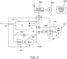
- Fig. 2 One example of an alternative implementation is shown in Fig. 2 .
- the start-up hydrogen supply and re-pressurisation of the start-up hydrogen tank is as for the example of Fig. 1 and the same parts are identified with the same reference numerals augmented with a '.
- the high pressure start-up air is provided to the fuel cell 10' using stored energy from batteries 200 to drive a motor 202 to operate a blower/compressor 204, instead of using a high pressure start-up air tank.
- Air is drawn from ambient C by the blower/compressor 204 when it is driven by the motor 202 operated by energy from a set of batteries 200.
- the start-up air is compressed and provided to the air inlet 14' via a heat exchanger HX2'. Start-up operation is otherwise as for the Fig. 1 example.
- the batteries 200 can be turned off and the motor 202 (and hence the blower/compressor 204) can be driven by the electricity from the fuel cell 10'.
- the air from the blower/compressor 204 will need to be cooled for proper operation of the fuel call 10'.
- the warm blower air is therefore cooled at a heat exchanger HX2' using the hydrogen passing through the hydrogen heat exchanger HX1' as transfer fluid.
- the pressure in the start-up hydrogen tank 20' can be restored in the same way as described for Fig. 1 .
- the batteries can be recharged using electricity from the fuel cell 10'.
- the batteries 200 can be replaced by some other source of electricity, e.g. a mains connection or an auxiliary motor e.g. a turbine powered by compressed air from e.g. an airport.
- the start-up architecture of this disclosure may have both the air flow and the hydrogen flow in the start-up phase provided by batteries/auxiliary motors. I.e. both the hydrogen start-up flow and the air start-up flow may be provided in a manner similar to the air flow of Fig. 2 .
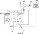
- An example is shown in Fig. 3 .
- a set of batteries 200" is used to drive a motor 202" to operate a blower/compressor 204" to drive ambient air C" to the fuel cell air input 14" via a heat exchanger HX2" as described for Fig. 2 .
- a set of batteries (which may be the same set 200" as shown in Fig. 3 or a separate battery set) drives a motor 302 which drives a blower 50" to drive hydrogen from the fuel cell output 15".
- the blower 50" is not being powered by the fuel cell.
- the unused hydrogen exiting the fuel cell 10" is drawn by the battery powered blower 50" via the mixer 60" (which is not operative as it is not yet powered by the fuel cell) and is provided to the hydrogen input 12".
- the batteries can be switched off and electricity from the fuel cell drives the blowers and the mixer.
- the fresh hydrogen is pumped, by a pump that may be powered by batteries or some auxiliary motor or power source, from the main hydrogen tank 400, and is evaporated using hot hydrogen exiting the fuel cell 10" at output 15" in the hydrogen heat exchanger HX1".
- the warmed fresh hydrogen leaving that heat exchanger HX1" is used as the transfer fluid for the air from the start-up air blower 204" heat exchanger HX2".
- additional heat exchangers may be needed to sufficiently warm the liquid hydrogen for use in the fuel cell 10" operation.
- the heat exchange fluid in such additional heat exchangers may come from oil in the blowers and motors as well as from the coolant used for the fuel cell.
- the heat exchangers used in any examples may be any known type of heat exchanger e.g. for liquid, gas or two-phase flow.
- the fluids flowing through the heat exchangers may be controlled according to the desired system operating point, depending on operating conditions, using control and/or bypass valves. Additional components for e.g. removing moisture, e.g. condensers, water separators, re-heaters etc. may also be used to protect against possible freezing issues.
- a coolant loop will typically also be provided, but this is well-known and has not been described or shown further here, since the present disclosure focuses on the novel start-up architecture aspects of the fuel cell arrangement.
- this disclosure provides an efficient, simple, and reliable architecture to ensure rapid and smooth start-up of a fuel cell assembly.
Landscapes
- Engineering & Computer Science (AREA)
- Life Sciences & Earth Sciences (AREA)
- Sustainable Development (AREA)
- Chemical & Material Sciences (AREA)
- Sustainable Energy (AREA)
- Chemical Kinetics & Catalysis (AREA)
- Manufacturing & Machinery (AREA)
- Electrochemistry (AREA)
- General Chemical & Material Sciences (AREA)
- Combustion & Propulsion (AREA)
- Power Engineering (AREA)
- Transportation (AREA)
- Mechanical Engineering (AREA)
- Fuel Cell (AREA)
Abstract
A start-up architecture for a fuel cell comprising: a fuel cell (10) having a hydrogen input (12) and an oxygen source input (14) and a hydrogen output (15) for outputting residual hydrogen not used in the fuel cell reaction, the hydrogen output connected to the hydrogen input via a mixer (60) in a hydrogen loop (102); a bypass loop (103), bypassing the mixer, between the hydrogen output and the hydrogen input; a control valve (CV1) in the bypass loop between the hydrogen output and the hydrogen input; a hydrogen start-up stored energy source (20, 20', 200") connected to the hydrogen input via a hydrogen start-up line; and an oxygen source start-up stored energy source (40, 200, 200") connected to the oxygen source input via an oxygen source start-up line, wherein, during a fuel cell start up process, the architecture is configured to provide hydrogen to the hydrogen input from the hydrogen start-up stored energy source, via the hydrogen start-up line, and to provide a source of oxygen to the oxygen source input from the oxygen source start-up stored energy source via the oxygen source start-up line, and wherein when start-up is completed, the oxygen source start-up line and the hydrogen start-up line are configured to close.
Description
- The present disclosure is concerned with providing a start-up architecture for a fuel cell, e.g. for an aircraft fuel cell.
- There is increasing pressure on the aerospace industry to switch the primary fuel for aircraft from hydrocarbons to more sustainable energy sources such as hydrogen. Hybrid fuel cell gas turbine systems, for example, include a gas turbine system and also use electric power generated by a fuel cell. Such systems comprise low-temperature fuel cells (e.g. proton exchange membrane fuel cells (PEMFCs)) that can increase fuel-to-electricity conversion efficiency and lower emissions of greenhouse gases. Hybrid fuel cell gas turbine systems use compressed gas/air to drive a turbine to drive an aircraft propeller and also use electric power that is generated by a hydrogen fuel cell. Improvements have been made possible in relation to the use of compact and efficient fuel cells by the ability to store sufficient hydrogen in a compressed and/or liquid form. The hydrogen required to generate electricity from the fuel cell is typically stored in a tank. This is made feasible by technologies that enable hydrogen to be cryogenically compressed for storage or to be stored in liquid form. The compression of hydrogen for storage requires the hydrogen to be very highly compressed (e.g. between 300 - 850 bar and less than 78K) or to be cryogenically cooled to liquid state at temperatures below 20K. Such low temperatures, however, are typically only needed to allow efficient storage of the hydrogen. The hydrogen then needs to be heated, in the system, for use by the fuel cell. Fuel cells require an additional start-up procedure to provide air and hydrogen to the fuel cell to generate energy. Once the fuel cell is operating, it generates enough energy to start loads to be powered by the fuel cell e.g. the main engines of an aircraft. The fuel cell may also generate electricity for the aircraft and may also act as an auxiliary power unit (APU). Typically, a fuel cell APU on an aircraft is started up on the ground and then operates throughout the whole flight.
- Known start-up procedures create a time delay in operating the fuel cell, are performed during ground operation and/or require external energy to start, combustion or complex, large and/or heavy components. There is a desire for an improved fuel cell start-up architecture.
- Accordingly, there is provided a start-up architecture for a fuel cell that makes use of stored energy sources to start up the fuel cell operation.
- Specifically, there is provided a start-up architecture for a fuel cell comprising: a fuel cell having a hydrogen input and an oxygen source input and a hydrogen output for outputting residual hydrogen not used in the fuel cell reaction, the hydrogen output connected to the hydrogen input via a mixer in a hydrogen loop; a bypass loop, bypassing the mixer, between the hydrogen output and the hydrogen input; a control valve in the bypass loop between the hydrogen output and the hydrogen input; a hydrogen start-up stored energy source connected to the hydrogen input via a hydrogen start-up line; and an oxygen source start-up stored energy source connected to the oxygen source input via an oxygen source start-up line, wherein, during a fuel cell start up process, the architecture is configured to provide hydrogen to the hydrogen input from the hydrogen start-up stored energy source, via the hydrogen start-up line, and to provide a source of oxygen to the oxygen source input from the oxygen source start-up stored energy source via the oxygen source start-up line, and wherein when start-up is completed, the oxygen source start-up line and the hydrogen start-up line are configured to close.
- A recharge circuit may also be provided to recharge the start-up energy sources after start-up is completed.
- Examples of a fuel cell start-up architecture will be described by way of example only, with reference to the drawings. It should be noted that these are examples only, and variations are possible within the scope of the claims.
-
Figure 1 is a schematic of an example fuel cell start-up architecture according to this disclosure. -
Figure 2 is a schematic of another example fuel cell start-up architecture according to this disclosure. -
Figure 3 is a schematic of another example fuel cell start-up architecture according to this disclosure. - A hydrogen fuel cell arrangement is already known for use in aircraft and the like and will not be described in detail here. In short, the
fuel cell 10 receives hydrogen from a hydrogen storage tank. The hydrogen in the tank is compressed or stored at an extremely low temperature and so needs to be appropriately conditioned before it can be used in thefuel cell 10. Where the hydrogen is cooled in the storage tank, it is then warmed in a heat exchanger where it undergoes heat exchange with air from the air loop, before it is provided as ahydrogen input 12 to thefuel cell 10, as fuel cells require the hydrogen to be at greater than 0°C, preferably between 5°C and 95°C. Air or some other source of oxygen is provided in an air loop to anoxygen input 14 of the fuel cell, and the oxygen and hydrogen undergo a chemical reaction to generate electricity to power aircraft systems. - For the
fuel cell 10 to operate, hydrogen and air must both be flowing through the fuel cell. As mentioned above, a procedure is required to manage the start-up phase of the system before there is a stable flow of hydrogen and air through the fuel cell. - The invention provides a start-up architecture to ensure the flow of both hydrogen and air to the fuel cell in a rapid and simple manner utilizing energy stored in high pressure tanks and/or batteries to initiate the flows.
- In a first example, as shown in
Fig. 1 , the start-up procedure utilises energy stored in high pressure air and hydrogen tanks. The arrangement includes a start-up hydrogen tank 20 storing pressurised hydrogen, and a high pressure start-up air tank 40 storing pressurised air. Theair tank 40 is connected to theoxygen input 14 of the fuel cell via a start-up air line 101. Thehydrogen tank 20 is connected to thehydrogen input 12 via a start-up hydrogen line 110 andhydrogen loop 102. Air (in an amount determined necessary for operation of the fuel cell) is first released from theair tank 40 via a first control valve CV4 in theair line 101 between the air tank and the fuelcell air inlet 14 and is fed to thefuel cell 10 via theair inlet 14. The amount of air required by the fuel cell may be controlled by a controller to ensure a smooth ramp up of power. - The flow of hydrogen into the
hydrogen loop 102 is started using the highpressure hydrogen tank 20. Hydrogen is released from thetank 20 via a control valve CV3 to thehydrogen inlet 12 of thefuel cell 10. - The
hydrogen loop 102 includes abypass loop 103. In normal operation of the fuel cell, hydrogen that exits the fuel cell at hydrogen output 15 (since the chemical reaction does not use all of the hydrogen provided to the fuel cell - usually a maximum of 95% is consumed in the energy generation) is recirculated to thefuel cell input 12 via thehydrogen loop 102. In the start-up phase, however, before the blower in thehydrogen loop 102 ramps up to the required operation point, a control valve CV1 in the bypass loop is opened during start-up to provide a short cut for the hydrogen. The hydrogen is forced through this loop due only to the pressure from the start-up hydrogen tank.. Theblower 50 andmixer 60 are not, at this stage, operable as they are not receiving power from the fuel cell, and so this diversion of the hydrogen allows for lower pressure losses and smooth operation at the beginning of fuel cell operation. - Once the hydrogen and air provided to the fuel cell in this start-up operation generate sufficient electrical energy to operate the
blower 50, the control valve CV1 in the bypass loop is closed, to close the bypass loop between thehydrogen output 15 and thehydrogen input 14. Also, at this time, the control valve CV3 between the hydrogen tank and thefuel cell 10 is also closed, thus closing the direct feeding of hydrogen from the tank to the fuel cell. The operation of these control valves CV1 and CV3 is based on measurements of mass flow, temperature and pressure in the recirculation loop. For safe operation, the temperature of the hydrogen provided to the fuel cell must exceed 0° (and preferably be in the range of 5°C to 95°C) and so the controller will control the opening of the control valves CV1 and CV3 to ensure stable temperature, pressure and mass flow in the recirculation loop while the blower and mixer, and other loads powered by the fuel cell, e.g. the main engines, are starting up. - Once start-up is completed, the normal fuel cell air and hydrogen loops operate to run the fuel cell.
- It is then possible to restore the pressure in the start-up air tank and the start-up hydrogen tank, so that they are available for the next start-up.
- The hydrogen tank pressure can be restored via the
hydrogen loop 102. In this phase, hydrogen from theloop 102 is provided back to thehydrogen tank 20 via areturn line 104 between thehydrogen loop 102 and thehydrogen tank 20. Thereturn line 104 includes a control valve CV2, a compressor C1 and a heat exchanger HX1. To recharge the pressure in the hydrogen tank, after start-up, the control valve CV2 in the return line is opened and the compressor C1 pressurises the recirculated hydrogen, which, by passage through the fuel cell in the start-up phase, has lost pressure, to the desired pressure for storage in the tank. The hydrogen from the recirculation loop, and after pressurisation by the compressor C1, is also at a higher temperature than required for storage in thetank 20. Therefore, the temperature is reduced, in thereturn line 104, by means of the heat exchanger HX1, in a heat exchange process with fresh hydrogen A from the main hydrogen tank (not shown here). - The re-pressurisation of the
air tank 40 is performed utilising air from the main air line 105 (which receives air for the normal fuel cell operation from e.g. bleed or RAM air, or from a compressor). Thismain air line 105 is connected to thefuel cell inlet 14, and is also connected to the start-up air tank 40 via anair return line 106 which includes a control valve CV5, a compressor C2 and a heat exchanger HX2. To re-pressurise the start-up air tank 40, the control valve CV5 in the airtank return line 106 is opened to allow flow of air from themain air line 105. The air is compressed by the compressor C2 in the return line and, like for the hydrogen, is cooled by the heat exchanger HX2, to the appropriate temperature for storage in theair tank 40. The heat transfer fluid for cooling the air in heat exchange HX2 may be the fresh hydrogen that was used to cool the return hydrogen, after it has passed through the return hydrogen heat exchanger HX1. - This fresh hydrogen from the main hydrogen tank is then used for normal fuel cell operation. The cold fresh hydrogen from the tank has been warmed by heat transfer with the return hydrogen at heat exchanger HX1 and the return air at heat exchanger HX2 and then then be fed, in the
hydrogen loop 102, to the mixer 60 (which is now operating stably after start-up) where it is mixed with residual hydrogen from the fuel cell, this being provided to themixer 60 via theblower 50. - The flow of fresh hydrogen from the main tank should be controlled so that the temperature of pressurised hydrogen and air from the respective return line heat exchangers is close to ambient, the fresh (liquid) hydrogen fully evaporates and the temperature after the mixer is above 0° (preferably between 5°C and 95°C) for safe use in the
fuel cell 10. - The compressors C1 and C2 and the blower, in the re-pressurising and the normal fuel cell operations are powered by the
fuel cell 10. - In addition, the pressure in the start-up
hydrogen tank 20 can be restored using excess hydrogen from the main tank. Due to extremely cold conditions inside the main hydrogen tank, part of the hydrogen in the tank will evaporate, raising the tank pressure, and may have to be released. Typically, a release valve is provided on the main tank. The present architecture may make use of the energy in this released pressure in the gaseous hydrogen B by connecting the relief valve to the start-up hydrogen tank to restore its high pressure after a start-up operation. The architecture may also be used in reverse, where the pressurised hydrogen is fed back to the main tank for pressure stabilisation purposes or for purging. - Although in the example in
Fig. 1 the lines to the start-up tanks are shown as separate lines, it is also feasible that these could use a single line using bypasses around the heat exchangers and compressors. - The example shown in
Fig. 1 and described above is one way of implementing the start-up as provided herein, by using energy from high pressure air and hydrogen storage tanks for the start-up procedure. It is, however, feasible that the energy for the start-up may be provided from other stored energy sources. One example of an alternative implementation is shown inFig. 2 . Here, the start-up hydrogen supply and re-pressurisation of the start-up hydrogen tank is as for the example ofFig. 1 and the same parts are identified with the same reference numerals augmented with a '. The high pressure start-up air, however, is provided to the fuel cell 10' using stored energy frombatteries 200 to drive amotor 202 to operate a blower/compressor 204, instead of using a high pressure start-up air tank. Air is drawn from ambient C by the blower/compressor 204 when it is driven by themotor 202 operated by energy from a set ofbatteries 200. The start-up air is compressed and provided to the air inlet 14' via a heat exchanger HX2'. Start-up operation is otherwise as for theFig. 1 example. - Once the fuel cell 10' is operating stably and generating electricity for the blower 50' and
mixer 60 and other loads e.g. engines, thebatteries 200 can be turned off and the motor 202 (and hence the blower/compressor 204) can be driven by the electricity from the fuel cell 10'. The air from the blower/compressor 204 will need to be cooled for proper operation of the fuel call 10'. The warm blower air is therefore cooled at a heat exchanger HX2' using the hydrogen passing through the hydrogen heat exchanger HX1' as transfer fluid. - The pressure in the start-up hydrogen tank 20' can be restored in the same way as described for
Fig. 1 . For the start-up air flow, the batteries can be recharged using electricity from the fuel cell 10'. In an alternative example, thebatteries 200 can be replaced by some other source of electricity, e.g. a mains connection or an auxiliary motor e.g. a turbine powered by compressed air from e.g. an airport. - Instead of the air and hydrogen tank example of
Fig. 1 or the hybrid example ofFig. 2 , the start-up architecture of this disclosure may have both the air flow and the hydrogen flow in the start-up phase provided by batteries/auxiliary motors. I.e. both the hydrogen start-up flow and the air start-up flow may be provided in a manner similar to the air flow ofFig. 2 . An example is shown inFig. 3 . - Again, parts of
Fig. 3 that correspond to those ofFig. 1 orFig. 2 will use the same reference number followed by a ". - In this example, a set of
batteries 200" is used to drive amotor 202" to operate a blower/compressor 204" to drive ambient air C" to the fuelcell air input 14" via a heat exchanger HX2" as described forFig. 2 . For the hydrogen flow, a set of batteries (which may be thesame set 200" as shown inFig. 3 or a separate battery set) drives amotor 302 which drives ablower 50" to drive hydrogen from thefuel cell output 15". When powered by the battery during start up, theblower 50" is not being powered by the fuel cell. The unused hydrogen exiting thefuel cell 10" is drawn by the battery poweredblower 50" via themixer 60" (which is not operative as it is not yet powered by the fuel cell) and is provided to thehydrogen input 12". Once thefuel cell 10" is operative and generates electricity, the batteries can be switched off and electricity from the fuel cell drives the blowers and the mixer. In this example, the fresh hydrogen is pumped, by a pump that may be powered by batteries or some auxiliary motor or power source, from themain hydrogen tank 400, and is evaporated using hot hydrogen exiting thefuel cell 10" atoutput 15" in the hydrogen heat exchanger HX1". The warmed fresh hydrogen leaving that heat exchanger HX1" is used as the transfer fluid for the air from the start-upair blower 204" heat exchanger HX2". Depending on the hydrogen temperature and operating conditions, additional heat exchangers may be needed to sufficiently warm the liquid hydrogen for use in thefuel cell 10" operation. The heat exchange fluid in such additional heat exchangers may come from oil in the blowers and motors as well as from the coolant used for the fuel cell. - The heat exchangers used in any examples may be any known type of heat exchanger e.g. for liquid, gas or two-phase flow. The fluids flowing through the heat exchangers may be controlled according to the desired system operating point, depending on operating conditions, using control and/or bypass valves. Additional components for e.g. removing moisture, e.g. condensers, water separators, re-heaters etc. may also be used to protect against possible freezing issues.
- As is known with fuel cells, a coolant loop will typically also be provided, but this is well-known and has not been described or shown further here, since the present disclosure focuses on the novel start-up architecture aspects of the fuel cell arrangement.
- By using stored energy sources to drive air and hydrogen to the fuel cell in the start-up phase and then enabling those sources to be restored during normal operation of the fuel cell, this disclosure provides an efficient, simple, and reliable architecture to ensure rapid and smooth start-up of a fuel cell assembly.
Claims (15)
- A start-up architecture for a fuel cell comprising:a fuel cell (10) having a hydrogen input (12) and an oxygen source input (14) and a hydrogen output (15) for outputting residual hydrogen not used in the fuel cell reaction, the hydrogen output connected to the hydrogen input via a mixer (60) in a hydrogen loop (102);a bypass loop (103), bypassing the mixer, between the hydrogen output and the hydrogen input;a control valve (CV1) in the bypass loop between the hydrogen output and the hydrogen input;a hydrogen start-up stored energy source (20, 20', 200") connected to the hydrogen input via a hydrogen start-up line; andan oxygen source start-up stored energy source (40, 200, 200") connected to the oxygen source input via an oxygen source start-up line, wherein, during a fuel cell start up process, the architecture is configured to provide hydrogen to the hydrogen input from the hydrogen start-up stored energy source, via the hydrogen start-up line, and to provide a source of oxygen to the oxygen source input from the oxygen source start-up stored energy source via the oxygen source start-up line, and wherein when start-up is completed, the oxygen source start-up line and the hydrogen start-up line are configured to close.
- The architecture of claim 1, further comprising a re-charge circuit for recharging the oxygen source start-up stored energy source and the hydrogen start-up stored energy source when start-up is completed.
- The architecture of claim 1 or 2, wherein the hydrogen start-up stored energy source is a tank of pressurised hydrogen.
- The architecture of any preceding claim, wherein the oxygen source start-up stored energy source is a tank of pressurised oxygen source.
- The architecture of any of claims 1 to 3, wherein the oxygen source start-up stored energy source is one or more batteries.
- The architecture of claim 1 or 2, wherein the oxygen source start-up stored energy source and the hydrogen start-up stored energy source are one or more batteries.
- The architecture of any of claims 1 to 4, further comprising an oxygen source start-up control valve in the oxygen source start-up control line and a hydrogen start-up control valve in the hydrogen start-up control line.
- The architecture of claim 5, wherein the oxygen source start-up line further comprises a motor and a blower and compressor between the one or more batteries and the oxygen source input and a heat exchanger to exchange heat between the oxygen source and hydrogen from a fresh hydrogen source.
- The architecture of claim 6, wherein the hydrogen start-up line further comprises a motor and a blower and compressor between the one or more batteries and the hydrogen input, and a heat exchanger to exchange heat between residual hydrogen from the fuel cell hydrogen output and hydrogen from a fresh hydrogen source.
- The architecture of claim 3 or 4 when dependent on claim 2, wherein the re-charge circuit comprises a hydrogen recharge line (104) between the hydrogen loop (102) and the tank of pressurised hydrogen.
- The architecture of claim 10, wherein the hydrogen recharge line includes a hydrogen recharge line control valve (CV2), a compressor and a heat exchanger (30).
- The architecture of claim 3 or 4 when dependent on claim 2, or claim 10 or 11, wherein the re-charge circuit comprises an oxygen source recharge line (106) between the air input and the tank of pressurised oxygen source.
- The architecture of claim 12, wherein the oxygen source recharge line (106) includes an oxygen source recharge line control valve (CV5), a compressor and a heat exchanger (HX2).
- The architecture of claim 6, wherein the one or more batteries are common to the oxygen source start-up stored energy source and the hydrogen start-up stored energy source.
- A fuel cell system including a start-up architecture as claimed in any preceding claim, a main hydrogen source to provide hydrogen to the hydrogen input when the hydrogen start-up line is closed and a main oxygen source to provide oxygen to the oxygen source input when the oxygen source input is closed.
Priority Applications (2)
| Application Number | Priority Date | Filing Date | Title |
|---|---|---|---|
| EP23461634.0A EP4503211A1 (en) | 2023-07-31 | 2023-07-31 | Fuel cell start-up architecture |
| US18/775,248 US20250046837A1 (en) | 2023-07-31 | 2024-07-17 | Fuel cell start-up architecture |
Applications Claiming Priority (1)
| Application Number | Priority Date | Filing Date | Title |
|---|---|---|---|
| EP23461634.0A EP4503211A1 (en) | 2023-07-31 | 2023-07-31 | Fuel cell start-up architecture |
Publications (1)
| Publication Number | Publication Date |
|---|---|
| EP4503211A1 true EP4503211A1 (en) | 2025-02-05 |
Family
ID=87550894
Family Applications (1)
| Application Number | Title | Priority Date | Filing Date |
|---|---|---|---|
| EP23461634.0A Pending EP4503211A1 (en) | 2023-07-31 | 2023-07-31 | Fuel cell start-up architecture |
Country Status (2)
| Country | Link |
|---|---|
| US (1) | US20250046837A1 (en) |
| EP (1) | EP4503211A1 (en) |
Citations (4)
| Publication number | Priority date | Publication date | Assignee | Title |
|---|---|---|---|---|
| US20030077489A1 (en) * | 2000-01-28 | 2003-04-24 | Katsumi Sahoda | Fuel cell power generation system |
| US20230035153A1 (en) * | 2019-02-21 | 2023-02-02 | ZeroAvia, Inc. | On-board oxygen booster for peak power in fuel cell systems |
| DE102021110378B4 (en) * | 2021-04-23 | 2023-03-16 | Dr. Ing. H.C. F. Porsche Aktiengesellschaft | Aircraft propulsion system, aircraft and method of operating an aircraft |
| CN219286469U (en) * | 2022-12-26 | 2023-06-30 | 江西洪都航空工业股份有限公司 | On-board hydrogen fuel cell structure for small and medium-sized aircraft |
-
2023
- 2023-07-31 EP EP23461634.0A patent/EP4503211A1/en active Pending
-
2024
- 2024-07-17 US US18/775,248 patent/US20250046837A1/en active Pending
Patent Citations (4)
| Publication number | Priority date | Publication date | Assignee | Title |
|---|---|---|---|---|
| US20030077489A1 (en) * | 2000-01-28 | 2003-04-24 | Katsumi Sahoda | Fuel cell power generation system |
| US20230035153A1 (en) * | 2019-02-21 | 2023-02-02 | ZeroAvia, Inc. | On-board oxygen booster for peak power in fuel cell systems |
| DE102021110378B4 (en) * | 2021-04-23 | 2023-03-16 | Dr. Ing. H.C. F. Porsche Aktiengesellschaft | Aircraft propulsion system, aircraft and method of operating an aircraft |
| CN219286469U (en) * | 2022-12-26 | 2023-06-30 | 江西洪都航空工业股份有限公司 | On-board hydrogen fuel cell structure for small and medium-sized aircraft |
Also Published As
| Publication number | Publication date |
|---|---|
| US20250046837A1 (en) | 2025-02-06 |
Similar Documents
| Publication | Publication Date | Title |
|---|---|---|
| US11268439B2 (en) | Cold-heat power generation device | |
| JP5436539B2 (en) | Alternative path cooling for high temperature fuel cells | |
| US7245034B2 (en) | Power system for a telecommunications facility | |
| US12479591B2 (en) | System for conditioning fuel for supplying an aircraft turbomachine, aircraft and method of use | |
| CN108123163B (en) | A high specific energy aviation fuel cell power generation device and control method | |
| JP2014104847A (en) | Cold use device for low-temperature liquefied fuel | |
| DK180671B1 (en) | Fuel cell system, use of it, and method of its operation | |
| JP2016506328A (en) | Air conditioning method and system for aircraft | |
| CN118254956A (en) | Fuel conditioning system | |
| US20250389230A1 (en) | Compressor bypass for low altitude operations | |
| EP4471262A1 (en) | Aircraft propulsion system with cooling architecture for liquid hydrogen superconducting system | |
| JP2005090636A (en) | Transportation system for liquefied hydrogen | |
| WO2010089883A1 (en) | Hybrid power generation system | |
| US20250046837A1 (en) | Fuel cell start-up architecture | |
| US20240421329A1 (en) | Hydrogen fuel system architecture | |
| US20210348840A1 (en) | Method for operating a reliquefaction system | |
| WO2017191676A1 (en) | Heat supply system | |
| US12221924B2 (en) | Combined gas turbine engine and fuel cell | |
| CN119408719B (en) | A superconducting hydrogen-electric propulsion aircraft thermal management system and working method | |
| CN114776474B (en) | Power system, aircraft and control method thereof | |
| US20260117681A1 (en) | Method and apparatus for pre-heating a process gas | |
| US20240178420A1 (en) | System for regulating pressure in liquid hydrogen fuel tank for a fuel cell electric vehicle | |
| EP4467788A1 (en) | Hydrogen fuel system architecture with oxygen separation | |
| WO2025119500A1 (en) | Fast ramping-up system for power generation, and method | |
| WO2017036431A1 (en) | Equipment for gas turbine output increasing and efficiency improvement |
Legal Events
| Date | Code | Title | Description |
|---|---|---|---|
| PUAI | Public reference made under article 153(3) epc to a published international application that has entered the european phase |
Free format text: ORIGINAL CODE: 0009012 |
|
| STAA | Information on the status of an ep patent application or granted ep patent |
Free format text: STATUS: THE APPLICATION HAS BEEN PUBLISHED |
|
| AK | Designated contracting states |
Kind code of ref document: A1 Designated state(s): AL AT BE BG CH CY CZ DE DK EE ES FI FR GB GR HR HU IE IS IT LI LT LU LV MC ME MK MT NL NO PL PT RO RS SE SI SK SM TR |
|
| STAA | Information on the status of an ep patent application or granted ep patent |
Free format text: STATUS: REQUEST FOR EXAMINATION WAS MADE |
|
| 17P | Request for examination filed |
Effective date: 20250805 |