EP4503078A1 - Opening and closing device - Google Patents
Opening and closing device Download PDFInfo
- Publication number
- EP4503078A1 EP4503078A1 EP22935430.3A EP22935430A EP4503078A1 EP 4503078 A1 EP4503078 A1 EP 4503078A1 EP 22935430 A EP22935430 A EP 22935430A EP 4503078 A1 EP4503078 A1 EP 4503078A1
- Authority
- EP
- European Patent Office
- Prior art keywords
- electrode
- opening
- terminal
- closing device
- magnets
- Prior art date
- Legal status (The legal status is an assumption and is not a legal conclusion. Google has not performed a legal analysis and makes no representation as to the accuracy of the status listed.)
- Pending
Links
Images




Classifications
-
- H—ELECTRICITY
- H01—ELECTRIC ELEMENTS
- H01H—ELECTRIC SWITCHES; RELAYS; SELECTORS; EMERGENCY PROTECTIVE DEVICES
- H01H31/00—Air-break switches for high tension without arc-extinguishing or arc-preventing means
- H01H31/26—Air-break switches for high tension without arc-extinguishing or arc-preventing means with movable contact that remains electrically connected to one line in open position of switch
- H01H31/32—Air-break switches for high tension without arc-extinguishing or arc-preventing means with movable contact that remains electrically connected to one line in open position of switch with rectilinearly-movable contact
-
- H—ELECTRICITY
- H01—ELECTRIC ELEMENTS
- H01H—ELECTRIC SWITCHES; RELAYS; SELECTORS; EMERGENCY PROTECTIVE DEVICES
- H01H33/00—High-tension or heavy-current switches with arc-extinguishing or arc-preventing means
- H01H33/02—Details
- H01H33/04—Means for extinguishing or preventing arc between current-carrying parts
- H01H33/18—Means for extinguishing or preventing arc between current-carrying parts using blow-out magnet
- H01H33/182—Means for extinguishing or preventing arc between current-carrying parts using blow-out magnet using permanent magnets
-
- H—ELECTRICITY
- H01—ELECTRIC ELEMENTS
- H01H—ELECTRIC SWITCHES; RELAYS; SELECTORS; EMERGENCY PROTECTIVE DEVICES
- H01H1/00—Contacts
- H01H1/50—Means for increasing contact pressure, preventing vibration of contacts, holding contacts together after engagement, or biasing contacts to the open position
- H01H1/54—Means for increasing contact pressure, preventing vibration of contacts, holding contacts together after engagement, or biasing contacts to the open position by magnetic force
- H01H2001/545—Means for increasing contact pressure, preventing vibration of contacts, holding contacts together after engagement, or biasing contacts to the open position by magnetic force having permanent magnets directly associated with the contacts
-
- H—ELECTRICITY
- H01—ELECTRIC ELEMENTS
- H01H—ELECTRIC SWITCHES; RELAYS; SELECTORS; EMERGENCY PROTECTIVE DEVICES
- H01H33/00—High-tension or heavy-current switches with arc-extinguishing or arc-preventing means
- H01H33/02—Details
- H01H33/04—Means for extinguishing or preventing arc between current-carrying parts
- H01H33/18—Means for extinguishing or preventing arc between current-carrying parts using blow-out magnet
- H01H33/185—Means for extinguishing or preventing arc between current-carrying parts using blow-out magnet using magnetisable elements associated with the contacts
Definitions
- the present disclosure relates to an opening and closing device which is opened/closed for current.
- a gas-insulated switchgear includes switches such as a circuit breaker, a disconnector, and a grounding switch in a container filled with an insulation gas (SF6 gas, dry air, or the like).
- SF6 gas insulation gas
- Each device is required to have a structure with electrodes facing each other and have performance to interrupt an arc that occurs when the electrodes are separated.
- SF6 gas insulation gas
- interruption can be performed by plain break which provides no quick-acting function, but, when the insulation gas is dry air having about 1/100 the interruption performance of SF6 gas, interruption is difficult to be performed.
- the plain break an arc generated when electrodes are separated is elongated by a driving device, to interrupt current.
- the quick break is such a feature that, with a quick-acting mechanism provided at one of electrodes, an opening speed is increased and an arc is elongated to a length needed for arc extinction within a time not causing contact damage, thus obtaining interruption performance.
- a male-side engaging unit and a female-side engaging unit are mechanically connected/disconnected by using a spring such that a quick-acting mechanism can be provided regardless of the tolerance of an installation space, whereby a structure that allows the quick-acting mechanism to be provided on a fixed-side electrode side is achieved.
- a magnet is provided in an opening and closing device, and an arc generated when current is interrupted is magnetically driven and interrupted.
- Patent Document 1 Japanese Laid-Open Patent Publication No. 2010-027479
- Patent Document 1 since a mechanical engagement mechanism using engaging units is employed, the structure is complicated and the processing cost and the number of assembly steps are increased, and, furthermore, sliding abrasion due to an increased number of operations causes an engaging failure.
- the male-side engaging unit and the female-side engaging unit are mechanically connected around the end of a fixed-side terminal, and the fixed-side electrode starts to be moved following a movable-side electrode toward a movable-side terminal disposed so as to face the fixed-side terminal.
- connection is released.
- the magnet is inserted inside the fixed-side terminal disposed outside the fixed-side electrode, and a position where the electrodes are separated (initial arc ignition position) is away from the fixed-side terminal and the magnet.
- An object of the present disclosure is to obtain an opening and closing device having high interruption performance and having a magnetic field intensity sufficient for arc extinction by a magnet when an arc has been generated, with a simple structure.
- the present disclosure is directed to an opening and closing device for opening/closing between a first terminal and a second terminal arranged so as to face each other, the opening and closing device including a first electrode which is provided at the first terminal and a second electrode which is provided at the second terminal and driven so as to be separable from the first electrode, wherein the first electrode and the second electrode are brought into contact with each other and kept in a conduction state therebetween, by an attraction force between magnets provided inside the electrodes.
- conduction between the first electrode and the second electrode is retained by the attraction force between the magnets inside the first electrode and the second electrode, and a magnetic field is formed around each electrode.
- the magnetic field necessary for arc extinction can be stably provided at the same time as when the arc is formed (the moment the electrodes are separated), so that interruption performance can be improved.
- a complicated engagement mechanism is not used, and thus the structure can be simplified, and the processing cost and the number of assembly steps can be reduced.
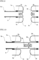
- FIG. 1 is a sectional view showing an opened state of an opening and closing device according to embodiment 1.
- Basic performance for opening a current path is configured by a first electrode 2a and a second electrode 3b facing each other.
- the first electrode 2a and the second electrode 3b are retained by guide members (not shown) or the like so as to move coaxially with a first terminal 1a and a second terminal 1b, respectively.
- the second electrode 3b is connected to a driving device (not shown), and can be driven and moved in the right-left direction of the sheet.
- the first electrode 2a and the second electrode 3b are coaxially-provided cylindrical columns, the outer circumferential edges of which are angled so as to be lowered backward.
- the first terminal 1a and the second terminal 1b are provided outside the first electrode 2a and the second electrode 3b, and are electrically connected through contacts 6a, 6b thereto, respectively.
- the first terminal 1a and the second terminal 1b are connected to other devices (not shown), and, when the first electrode 2a and the second electrode 3b come into contact with each other, a current conduction path is formed and power is transmitted. Further, an effect of relaxing an electric field and protecting the electrodes from damage due to an arc is also provided.
- magnets 5a, 5b are provided in hollows at center portions of the first electrode 2a and the second electrode 3b, and are retained by covers 4a, 4b mounted to magnet surfaces facing each other, respectively.
- a combination of magnetic-pole directions of the magnets 5a, 5b causes an attraction force to act between the electrodes when the first electrode 2a and the second electrode 3b come into contact with each other.
- the material of the covers 4a, 4b is a non-magnetic metal material such as tungsten copper, or a resin material such as PTFE (polytetrafluoroethylene).
- a fixed stopper 7a is mounted to the first terminal 1a
- a moving stopper 8a and a spring 9 are mounted to the first electrode 2a.
- the spring 9 is provided between the fixed stopper 7a and the moving stopper 8a, and, when the first electrode 2a is moved in the right-left direction of the sheet, the moving stopper 8a is also moved in the right-left direction of the sheet, whereby the spring 9 is expanded and contracted.
- the fixed stopper 7a is not moved, that is, the position thereof is not changed.
- the first electrode 2a is fastened to the first terminal 1a by the spring 9.
- FIG. 1 shows an opened state of the opening and closing device according to embodiment 1.
- the second electrode 3b is connected to the driving device (not shown), and is driven in the right-left direction of the sheet of FIG. 1 to open/close the path between the electrodes.
- FIG. 2 shows a closed state of the opening and closing device according to embodiment 1, and is a sectional view when the second electrode 3b is closed.
- a current path is formed.
- power flowing into the first terminal 1a connected to another device is transmitted to the first electrode 2a through the contact 6a, and, through the second electrode 3b in contact with the first electrode 2a, flows into the contact 6b and the second terminal 1b, so that the power can be transmitted to another device.
- first electrode 2a and the second electrode 3b are engaged and connected by the magnetic attraction force between the magnets 5a, 5b provided in the hollows at the center portions thereof, and contact between the electrodes is maintained and conduction therebetween is retained even if the second electrode 3b is moved in the right direction of the sheet by the driving device (not shown) .
- FIG. 3 shows an opening operation of the opening and closing device according to embodiment 1, and is a sectional view in which, after being engaged and connected by the magnetic attraction force, the second electrode 3b is moved to an opened position thereof.
- the driving device not shown
- the first electrode 2a is moved in the right direction of the sheet together with the second electrode 3b.
- the moving stopper 8a mounted to the first electrode 2a is also moved in the right direction of the sheet, whereby the spring 9 stores force.
- the fixed stopper 7a is mounted to the first terminal 1a and thus is not moved, that is, the position thereof is not changed.
- the restoring force of the spring 9 and the attraction force between the magnets 5a, 5b are balanced, engagement by magnetism is released, and the first electrode 2a and the second electrode 3b are separated by the restoring force of the spring 9.
- the attraction force between the magnet 5a of the first electrode 2a and the magnet 5b of the second electrode 3b driven to an opening-path direction while conduction therebetween is retained, and the restoring force of the spring 9 fastened to the first electrode 2a are used.
- FIG. 4 is a sectional view in which an arc generated between the electrodes after release of engagement by magnetism is being interrupted, when the opening and closing device according to embodiment 1 is opened.
- the restoring force of the spring 9 and the attraction force between the magnets 5a, 5b are balanced, engagement by magnetism is released and the first electrode 2a and the second electrode 3b are separated by the restoring force of the spring 9.
- an arc 10 is generated between the first electrode 2a and the second electrode 3b if current is being applied.
- the generated arc 10 is rotated in the circumferential direction of the electrodes by the magnetic field generated by the magnets 5a, 5b.
- an arcing point (end portion of arc 10) at the surface of each electrode gradually moves toward an outer circumference of the electrode.
- the second electrode 3b is returned to the opened position thereof by the driving device (not shown), and the first electrode 2a is returned to an opened position thereof by the restoring force of the spring 9 after repeating minute vibration in the right-left direction of the sheet.
- the first electrode 2a and the second electrode 3b are magnetically engaged and connected by the attraction force between the magnets 5a, 5b provided in the hollows at the center portions thereof.
- the structure is simple and an engaging unit having a complicated structure is unnecessary, so that processing cost and the number of assembly steps are reduced, sliding abrasion due to an increased number of operations does not occur, and an engagement mechanism can stably operate.
- the magnets 5a, 5b as the engagement mechanism, the magnetic field necessary for extinction of the arc 10 can be stably provided at the same time as when the arc is formed (the moment the electrodes are separated), so that interruption performance is improved and electrode wear can be reduced.
- the magnetic field generated by the magnets 5a, 5b causes the arc 10 to rotate in the circumferential direction of the electrodes to cool the arc 10, so that current interruption performance can be improved.
- current mainly has a component in a direction perpendicular to the surface of each electrode (axis direction).
- Arc current in the axis direction and the magnetic field in the radial direction generated by the magnets 5a, 5b cause Lorentz force to act in the circumferential direction, and thus the arc 10 rotates on the outer circumferences of the first electrode 2a and the second electrode 3b.
- the magnets 5a, 5b are provided in the hollows at the center portions of the first electrode 2a and the second electrode 3b, and thus the magnets 5a, 5b are always located near an arcing point of the arc 10 (end portion of arc 10).
- the magnetic field necessary for extinction of the arc 10 can be stably provided at the same time as when the electrodes are separated.
- a magnetic member such as iron may be combined, whereby a force for retaining engagement by the magnetism of magnets can be adjusted.
- the quick break is such a feature that, with a quick-acting mechanism provided at one of electrodes, an opening speed is increased to elongate an arc to a length needed for arc extinction within a time not causing contact damage, thus improving interruption performance.
- the magnetic field between the magnets 5a, 5b causes the arc 10 to rotate at the same time as when the electrodes are separated, and current interruption performance is improved, so that opening at high speed is unnecessary and the necessary opening speed can be reduced. Therefore, a special quick-acting mechanism is unnecessary, and the load of the spring 9 can also be reduced, leading to reduction in size and weight as the entire device.
- a magnetic material such as iron is used as a material for the covers 4a, 4b for retaining the magnets 5a, 5b
- a magnetic field is strong at surfaces of the covers 4a, 4b, so that a foreign material which is a magnetic material generated by the arc 10 is easily attached, and engagement might become unstable. Therefore, if a non-magnetic metal material such as tungsten copper, or a resin material such as PTFE is used, a foreign material is inhibited from being attached and stable engagement can be provided.
- the resin material such as PTFE
- the resin material comes into direct contact with the arc 10 and comes into contact with radiation light of the arc 10, whereby ablation gas generated from the resin material cools the arc 10 (ablation cooling), thereby improving current interruption performance.
- the resin material such as PTFE has a low thermal conductivity, and thus an effect of transmitting heat of the arc 10 to the magnets 5a, 5b and inhibiting thermal demagnetization is also provided.
- the covers 4a, 4b may have a shape so as to cover not only end surfaces as shown in the drawing, but also the periphery thereof.
- the arc 10 is formed at the surfaces of the first electrode 2a and the second electrode 3b. If a mark (burn mark) of the arc 10 is left, or a foreign metal or the like is thereby attached, a force for retaining engagement by magnetism may vary. It has been known that an arcing point (end portion of arc 10) at the surface of each of the first electrode 2a and the second electrode 3b gradually moves toward an outer circumference of each electrode as the arc 10 is continuously rotated by the magnetic field of the magnets 5a, 5b.
- the outer circumferential edge of the first electrode 2a and the outer circumferential edge of the second electrode 3b are angled so as to be separated from each other toward the outer circumference of each electrode, and, even if a mark (burn mark) of the arc 10, a foreign metal, or the like is attached, the force for retaining engagement by magnetism does not vary.
- FIG. 5 is a sectional view showing an opened state of an opening and closing device according to embodiment 2.
- Basic performance for opening a current path is configured by a first electrode 2c and a second electrode 3d facing each other.
- the first electrode 2c and the second electrode 3d are retained by guide members (not shown) or the like so as to move coaxially with the first terminal 1a and the second terminal 1b, respectively.
- the second electrode 3d is connected to a driving device (not shown), and can be moved in the right-left direction of the sheet.
- the second electrode 3d is a coaxially-provided cylindrical column, the outer circumferential edge of which may be angled so as to be lowered backward.
- the first electrode 2c is also a coaxially-provided cylindrical column, and has a recessed hollow portion at a center of an end portion such that a protruding end portion of the second electrode 3d is fitted into the hollow portion.
- the hollow portion has a taper structure with an inner diameter decreasing toward the bottom on the deep side.
- the first terminal 1a and the second terminal 1b are provided outside the first electrode 2c and the second electrode 3d, and are electrically connected through the contacts 6c, 6d thereto, respectively.
- the first terminal 1a and the second terminal 1b are connected to other devices (not shown), and, when the first electrode 2e and the second electrode 3d come into contact with each other, a current conduction path is formed and power is transmitted. Further, an effect of relaxing an electric field and protecting the electrodes from damage due to the arc 10 is also provided.
- a magnet 5d is provided in a hollow at a center portion of the second electrode 3d, and is retained by mounting a cover 4d thereto.
- a magnet 5c is provided inside a thickness part of the first electrode 2e where the hollow portion is present, and is retained by mounting a cover 4c thereto.
- the material of the covers 4c, 4d is a non-magnetic metal material such as tungsten copper, or a resin material such as PTFE.
- a fixed stopper 7c is mounted to the first terminal 1a, and a moving stopper 8a and a spring 9 are mounted to the first electrode 2c.
- the spring 9 is provided between the fixed stopper 7c and the moving stopper 8a, and, when the first electrode 2c is moved in the right-left direction of the sheet, the moving stopper 8a is also moved in the right-left direction of the sheet, whereby the spring 9 is expanded and contracted.
- the fixed stopper 7c is not moved, that is, the position thereof is not changed.
- the first electrode 2c is fastened to the first terminal 1a by the spring 9.
- FIG. 6 shows an opening operation of the opening and closing device according to embodiment 2, and is a sectional view in which, after being engaged and connected by the magnetic attraction force, the second electrode is moved to an opened position thereof.
- the second electrode 3d is connected to the driving device (not shown), and is driven in the right-left direction of the sheet of FIG. 6 to open/close the path between the electrodes. When the second electrode 3d comes into contact with the first electrode 2c, a current path is formed.
- the end of the second electrode 3d is in contact with a deepest portion of the hollow portion of the first electrode 2c.
- engagement by magnetism is maintained by the attraction force between the magnets 5c, 5d, and contact between the electrodes is retained even if the second electrode 3d is moved by the driving device (not shown).
- a combination of directions of the magnets 5c, 5d causes an attraction force to act between the electrodes when the first electrode 2c and the second electrode 3d come into contact with each other, but, when the electrodes are slightly separated from each other after engagement is released, a force in a repulsion direction occurs.
- the first electrode 2c is accelerated in the left direction of the sheet immediately after the electrodes are separated, and the opening speed can be increased.
- the outer diameter of the second electrode 3d may be smaller and thus the mass thereof decreases, and the structure of the driving device for driving the second electrode 3d can be downsized.
- FIG. 7 is a sectional view showing an opened state of an opening and closing device according to embodiment 3.
- Basic performance for opening a current path is configured by a first electrode 2e and a second electrode 3f facing each other.
- the first electrode 2e and the second electrode 3f are retained by guide members (not shown) or the like so as to move coaxially with the first terminal 1a and the second terminal 1b, respectively.
- the second electrode 3f is connected to a driving device (not shown), and can be moved in the right-left direction of the sheet.
- the first electrode 2e is a coaxially-provided cylindrical column, the outer circumferential edge of which may be angled so as to be lowered backward.
- the second electrode 3f is also a coaxially-provided cylindrical column, and has a recessed hollow portion at a center of an end portion such that a protruding end portion of the first electrode 2e is fitted into the hollow portion.
- the hollow portion has a taper structure with an inner diameter decreasing toward the bottom on the deep side.
- the first terminal 1a and the second terminal 1b are provided outside the first electrode 2e and the second electrode 3f, and are electrically connected through contacts 6e, 6f thereto.
- the first terminal 1a and the second terminal 1b are connected to other devices (not shown), and, when the first electrode 2e and the second electrode 3f come into contact with each other, a current conduction path is formed and power is transmitted. Further, an effect of relaxing an electric field and protecting the electrodes from damage due to the arc 10 is also provided.
- a magnet 5e is provided in a hollow at a center portion of the first electrode 2e, and is retained by mounting a cover 4e thereto.
- a magnet 5f is provided inside a thickness part of the second electrode 3f where the hollow portion is present, and is retained by mounting a cover 4f thereto.
- a combination of magnetic-pole directions of the magnet 5e, 5f causes an attraction force to act between the electrodes when the first electrode 2e and the second electrode 3f come into contact with each other.
- the material of the covers 4e, 4f is a non-magnetic metal material such as tungsten copper, or a resin material such as PTFE.
- a fixed stopper 7e is mounted to the first terminal 1a
- a moving stopper 8a and a spring 9 are mounted to the first electrode 2e.
- the spring 9 is provided between the fixed stopper 7a and the moving stopper 8a, and, when the first electrode 2e is moved in the right-left direction of the sheet, the moving stopper 8a is also moved in the right-left direction of the sheet, whereby the spring 9 is expanded and contracted.
- the fixed stopper 7e is not moved, that is, the position thereof is not changed.
- the first electrode 2e is fastened to the first terminal 1a by the spring 9.
- FIG. 8 shows an opening operation of the opening and closing device according to embodiment 3, and is a sectional view in which, after being engaged and connected by the magnetic attraction force, the second electrode is moved to an opened position thereof.
- the second electrode 3f is connected to the driving device (not shown), and is driven in the right-left direction of the sheet of FIG. 8 to open/close the path between the electrodes. When the second electrode 3f comes into contact with the first electrode 2e, a current path is formed.
- the end of the first electrode 2e is in contact with a deepest portion of the hollow portion of the second electrode 3f.
- engagement by magnetism is maintained by the attraction force between the magnet 5e, 5f, and contact between the electrodes is retained even if the second electrode 3f is moved by the driving device (not shown).
- the outer diameter of the first electrode 2e may be smaller and thus the mass thereof decreases, and the spring 9 for fastening the first electrode 2e can be downsized.
- FIG. 9 is a sectional view showing an opened state of an opening and closing device according to embodiment 4.
- Basic performance for opening a current path is configured by a first electrode 2g and a second electrode 3h facing each other.
- the first electrode 2g and the second electrode 3h are retained by guide members (not shown) or the like so as to move coaxially with the first terminal 1a and the second terminal 1b, respectively.
- the second electrode 3h is connected to a driving device (not shown), and can be moved in the right-left direction of the sheet.
- the second electrode 3h is a coaxially-provided cylindrical column, the end portion of which is formed in a hemispherical shape.
- the first electrode 2g is also a coaxially-provided cylindrical column, and has a recessed hemispherical concave at a center of an end portion such that the second electrode 3h having a protruding shape is fitted into the concave.
- An outer circumferential edge of the first electrode 2g is rounded such that an electric field is not concentrated.
- the recessed shape of the first electrode 2g and the protruding shape of the second electrode 3h may be reversed.
- the first terminal 1a and the second terminal 1b are provided outside the first electrode 2g and the second electrode 3h, and are electrically connected through the contacts 6a, 6b thereto, respectively.
- the first terminal 1a and the second terminal 1b are connected to other devices (not shown), and, when the first electrode 2g and the second electrode 3h come into contact with each other, a current conduction path is formed and power is transmitted. Further, an effect of relaxing an electric field and protecting the electrodes from damage due to the arc 10 is also provided.
- the magnets 5a, 5b are provided in hollows at center portions of the first electrode 2g and the second electrode 3h, respectively.
- a combination of magnetic-pole directions of the magnets 5a, 5b causes an attraction force to act between the electrodes when the first electrode 2g and the second electrode 3h come into contact with each other.
- a fixed stopper 7a is mounted to the first terminal 1a
- a moving stopper 8a and a spring 9 are mounted to the first electrode 2a.
- the spring 9 is provided between the fixed stopper 7a and the moving stopper 8a, and, when the first electrode 2a is moved in the right-left direction of the sheet, the moving stopper 8a is also moved in the right-left direction of the sheet, whereby the spring 9 is expanded and contracted.
- the fixed stopper 7a is not moved, that is, the position thereof is not changed.
- the first electrode 2a is fastened to the first terminal 1a by the spring 9.
- FIG. 10 shows an opening operation of the opening and closing device according to embodiment 4, and is a sectional view in which, after being engaged and connected by the magnetic attraction force, the second electrode is moved to an opened position thereof.
- the second electrode 3h is connected to the driving device (not shown), and is driven in the right-left direction of the sheet of FIG. 10 to open/close the path between the electrodes.
- the driving device not shown
- a hemispherical convex surface of the second electrode 3h is in contact with a hemispherical concave surface of the first electrode 2g.
- engagement by magnetism is maintained by the attraction force between the magnets 5a, 5b, and contact between the electrodes is retained even if the second electrode 3h is moved by the driving device (not shown).
- An engagement mechanism using magnetism can provide strong engagement force as long as contact surfaces of the electrodes are properly fitted with each other. However, it is considered that, in a case where the electrode is deviated from the axis or is inclined, the distance between the magnets becomes larger and the attraction force (engagement force) decreases.
- the concave end of the first electrode 2g and the convex end of the second electrode 3h are each formed in a hemispherical shape and are engaged with each other, and thus, even if the first electrode 2g or the second electrode 3h is deviated from the axis or is inclined at the time of closing, the distance between the magnets 5a, 5b does not become larger and engagement can be stably retained.
- FIG. 11 is a sectional view showing an opened state of an opening and closing device according to embodiment 5.
- Basic performance to open a current path is configured by a first electrode 2a and a second electrode 3b facing each other.
- the first electrode 2a and the second electrode 3b are retained by guide members (not shown) or the like so as to move coaxially with the first terminal 1a and the second terminal 1b, respectively.
- the second electrode 3b is connected to the driving device (not shown), and can be moved in the right-left direction of the sheet.
- the first electrode 2a and the second electrode 3b are coaxially-provided cylindrical columns, the outer circumferential edges of which may be angled so as to be lowered backward.
- the first terminal 1a and the second terminal 1b are provided outside the first electrode 2a and the second electrode 3b, and are electrically connected through the contacts 6a, 6b thereto.
- the first terminal 1a and the second terminal 1b are connected to other devices (not shown), and, when the first electrode 2a and the second electrode 3b come into contact with each other, a current conduction path is formed and power is transmitted. Further, an effect of relaxing an electric field and protecting the electrodes from damage due to the arc 10 is also provided.
- the magnets 5a, 5b are provided in hollows at center portions of the first electrode 2a and the second electrode 3b, and are retained by mounting the covers 4a, 4b thereto, respectively.
- a combination of magnetic-pole directions of the magnets 5a, 5b causes an attraction force to act between the electrodes when the first electrode 2a and the second electrode 3b come into contact with each other.
- the material of the covers 4a, 4b is a non-magnetic metal material such as tungsten copper, or a resin material such as PTFE.
- magnets 11a, 11b are respectively provided inside the first terminal 1a and the second terminal 1b, and increase the intensity of the magnetic field in the radial direction between the electrodes.
- the magnets 11a, 11b may be combined with magnetic members.
- a fixed stopper 7a is mounted to the first terminal 1a, and a moving stopper 8a and a spring 9 are mounted to the first electrode 2a.
- the spring 9 is provided between the fixed stopper 7a and the moving stopper 8a, and, when the first electrode 2a is moved in the right-left direction of the sheet, the moving stopper 8a is also moved in the right-left direction of the sheet, whereby the spring 9 is expanded and contracted.
- the fixed stopper 7a is not moved, that is, the position thereof is not changed.
- the first electrode 2a is fastened to the first terminal 1a by the spring 9.
- the magnets 11a, 11b may be provided inside the first terminal 1a and the second terminal 1b in each structure in embodiments 2 to 4.
- FIG. 12 shows an arc-generated state when the opening and closing device according to embodiment 5 is opened, and is a sectional view in which an arc generated between the electrodes after release of engagement by the magnetic attraction force is being interrupted.
- the arc 10 is rotated in the circumferential direction of the electrodes by the magnetic field generated by the magnets 5a, 5b and the magnetic field generated by the magnets 11a, 11b, to cool the arc 10, whereby current interruption performance can be further improved.
- current mainly has a component in a direction perpendicular to each electrode surface (axis direction). Due to the arc current in the axis direction and the magnetic fields in the radial direction generated by the magnets 5a, 5b and the magnets 11a, 11b, Lorentz force acts in the circumferential direction, and thus the arc 10 is rotated on the first electrode 2a and the second electrode 3b.
- the inserted magnets 11a, 11b increase the magnetic field in the radial direction generated between the electrodes, thereby further improving interruption performance.
- the magnets 11a, 11b may be combined with magnetic members.
- a middle-side part of the arc 10 becomes farther from the magnets 5a, 5b, and thus, at the middle-side part, the intensity of the magnetic field is weak and the middle-side part is less subjected to rotational driving by magnetism.
- the inserted magnets 11a, 11b increase the intensity of the magnetic field, and thus, even if the distance between the electrodes becomes larger, the arc 10 can be rotated not only at the end portions of the arc 10 but also the middle-side part, thereby further improving current interruption performance.
- FIG. 13 is a sectional view showing an opened state of an opening and closing device according to embodiment 6.
- Basic performance for opening a current path is configured by a first electrode 2a and a second electrode 3b facing each other.
- the first electrode 2a and the second electrode 3b are retained by guide members (not shown) or the like so as to move coaxially with the first terminal 1a and the second terminal 1b, respectively.
- the second electrode 3b is connected to a driving device (not shown), and can be moved in the right-left direction of the sheet.
- the first electrode 2a and the second electrode 3b are coaxially-provided cylindrical columns, the outer circumferential edges of which are angled so as to be lowered backward.
- the first terminal 1a and the second terminal 1b are provided outside the first electrode 2a and the second electrode 3b, and are electrically connected through the contacts 6a, 6b thereto, respectively.
- the first terminal 1a and the second terminal 1b are connected to other devices (not shown), and, when the first electrode 2a and the second electrode 3b come into contact with each other, a current conduction path is formed and power is transmitted. Further, an effect of relaxing an electric field and protecting the electrodes from damage due to the arc 10 is also provided.
- the magnets 5a, 5b are provided in hollows at center portions of the first electrode 2a and the second electrode 3b, and are retained by mounting the covers 4a, 4b thereto, respectively.
- a combination of magnetic-pole directions of the magnets 5a, 5b causes an attraction force to act between the electrodes when the first electrode 2a and the second electrode 3b come into contact with each other.
- the material of the covers 4a, 4b is a non-magnetic metal material such as tungsten copper, or a resin material such as PTFE.
- a fixed stopper 7a and a limiting stopper 12 are mounted to the first terminal 1a, and a moving stopper 8c and a spring 9 are mounted to the first electrode 2a.
- the spring 9 is provided between the fixed stopper 7a and the moving stopper 8c, and, when the first electrode 2a is moved in the right-left direction of the sheet, the moving stopper 8c is also moved in the right-left direction of the sheet, whereby the spring 9 is expanded and contracted.
- the fixed stopper 7a and the limiting stopper 12 are fixed to the first terminal 1a, that is, the positions thereof are not changed.
- the first electrode 2a is fastened to the first terminal 1a by the spring 9.
- the limiting stopper 12 may be provided at the first terminal 1a in each structure in embodiments 2 to 5.
- FIG. 14 shows an opening operation of the opening and closing device according to embodiment 6, and is a sectional view in which, after being engaged and connected by the magnetic attraction force, the moving stopper 8c is in contact with the limiting stopper 12. Engagement by magnetism is maintained by the attraction force between the magnets 5a, 5b provided in the hollows at the center portions of the first electrode 2a and the second electrode 3b, and contact between the electrodes is retained even if the second electrode 3b is moved by the driving device (not shown).
- the spring is inserted between the moving stopper 8c mounted to the first electrode 2a and the fixed stopper 7a mounted to the first terminal 1a, and, when the moving stopper 8c is moved in the right direction of the sheet together with the first electrode 2a, the spring 9 stores a force.
- the moving stopper 8c comes into contact with the limiting stopper 12 which is a stop portion, and the force storing by the spring 9 is forcibly limited at a position in the left direction of the sheet with respect to a position where the restoring force of the spring 9 and the attraction force between the magnets 5a, 5b are balanced in embodiment 1.
- a displacement amount of the spring 9 for storing a force is constant, and the restoring force is smaller than the attraction force between the magnets 5a, 5b.
- the moving stopper 8c provided at the first electrode 2a comes into contact with the limiting stopper 12 which is the stop portion provided at the first terminal 1a, whereby movement of the first electrode 2a is stopped.
- the second electrode 3b is continuously moved in the right direction of the sheet by the driving device (not shown).
- the driving device (not shown) causes a force to act in a repulsion direction, in addition to the restoring force of the spring 9, between the first electrode 2a and the second electrode 3b, and engagement by magnetism is released when such forces and the attraction force between the magnets 5a, 5b are balanced.
- the first electrode 2a After engagement is released, the first electrode 2a starts to be moved in the left direction of the sheet by the restoring force of the spring 9. In addition, after the first electrode 2a and the second electrode 3b are separated, the arc 10 is generated between the first electrode 2a and the second electrode 3b if current is being applied.
Landscapes
- Arc-Extinguishing Devices That Are Switches (AREA)
Abstract
Description
- The present disclosure relates to an opening and closing device which is opened/closed for current.
- In general, a gas-insulated switchgear includes switches such as a circuit breaker, a disconnector, and a grounding switch in a container filled with an insulation gas (SF6 gas, dry air, or the like). Each device is required to have a structure with electrodes facing each other and have performance to interrupt an arc that occurs when the electrodes are separated. In addition, it has been known that, when the insulation gas inside the gas-insulated switchgear is SF6 gas having high interruption performance, interruption can be performed by plain break which provides no quick-acting function, but, when the insulation gas is dry air having about 1/100 the interruption performance of SF6 gas, interruption is difficult to be performed. Here, in the plain break, an arc generated when electrodes are separated is elongated by a driving device, to interrupt current.
- As technology for improving current interruption performance, quick break and magnetic driving have been known. The quick break is such a feature that, with a quick-acting mechanism provided at one of electrodes, an opening speed is increased and an arc is elongated to a length needed for arc extinction within a time not causing contact damage, thus obtaining interruption performance. Specifically, in Patent Document 1, a male-side engaging unit and a female-side engaging unit are mechanically connected/disconnected by using a spring such that a quick-acting mechanism can be provided regardless of the tolerance of an installation space, whereby a structure that allows the quick-acting mechanism to be provided on a fixed-side electrode side is achieved. In the magnetic driving, as described in Patent Document 1, a magnet is provided in an opening and closing device, and an arc generated when current is interrupted is magnetically driven and interrupted.
- Patent Document 1:
Japanese Laid-Open Patent Publication No. 2010-027479 - However, in Patent Document 1, since a mechanical engagement mechanism using engaging units is employed, the structure is complicated and the processing cost and the number of assembly steps are increased, and, furthermore, sliding abrasion due to an increased number of operations causes an engaging failure.
- In addition, in Patent Document 1, the male-side engaging unit and the female-side engaging unit are mechanically connected around the end of a fixed-side terminal, and the fixed-side electrode starts to be moved following a movable-side electrode toward a movable-side terminal disposed so as to face the fixed-side terminal. When the restoring force of the spring and the frictional force between the engaging units are balanced during movement of the electrodes, connection is released. The magnet is inserted inside the fixed-side terminal disposed outside the fixed-side electrode, and a position where the electrodes are separated (initial arc ignition position) is away from the fixed-side terminal and the magnet. The larger a distance from the magnet is, the smaller the intensity of the magnetic field generated by the magnet is, and thus the intensity of the magnetic field sufficient to magnetically drive an arc cannot be obtained during a period from when electrodes have just been separated to when the fixed-side electrode reaches a certain distance.
- The present disclosure has been made to solve the above-described problem. An object of the present disclosure is to obtain an opening and closing device having high interruption performance and having a magnetic field intensity sufficient for arc extinction by a magnet when an arc has been generated, with a simple structure.
- The present disclosure is directed to an opening and closing device for opening/closing between a first terminal and a second terminal arranged so as to face each other, the opening and closing device including a first electrode which is provided at the first terminal and a second electrode which is provided at the second terminal and driven so as to be separable from the first electrode, wherein the first electrode and the second electrode are brought into contact with each other and kept in a conduction state therebetween, by an attraction force between magnets provided inside the electrodes.
- According to the present disclosure, conduction between the first electrode and the second electrode is retained by the attraction force between the magnets inside the first electrode and the second electrode, and a magnetic field is formed around each electrode. Thus, the magnetic field necessary for arc extinction can be stably provided at the same time as when the arc is formed (the moment the electrodes are separated), so that interruption performance can be improved. In addition, a complicated engagement mechanism is not used, and thus the structure can be simplified, and the processing cost and the number of assembly steps can be reduced.
-
- [
FIG. 1] FIG. 1 is a sectional view showing an opened state of an opening and closing device according to embodiment 1. - [
FIG. 2] FIG. 2 is a sectional view showing a closed state of the opening and closing device according to embodiment 1. - [
FIG. 3] FIG. 3 is a sectional view showing an opening operation of the opening and closing device according to embodiment 1. - [
FIG. 4] FIG. 4 is a sectional view showing an arc-generated state when the opening and closing device according to embodiment 1 is opened. - [
FIG. 5] FIG. 5 is a sectional view showing an opened state of an opening and closing device according to embodiment 2. - [
FIG. 6] FIG. 6 is a sectional view showing an opening operation of the opening and closing device according to embodiment 2. - [
FIG. 7] FIG. 7 is a sectional view showing an opened state of an opening and closing device according to embodiment 3. - [
FIG. 8] FIG. 8 is a sectional view showing an opening operation of the opening and closing device according to embodiment 3. - [
FIG. 9] FIG. 9 is a sectional view showing an opened state of an opening and closing device according to embodiment 4. - [
FIG. 10] FIG. 10 is a sectional view showing an opening operation of the opening and closing device according to embodiment 4. - [
FIG. 11] FIG. 11 is a sectional view showing an opened state of an opening and closing device according to embodiment 5. - [
FIG. 12] FIG. 12 is a sectional view showing an arc-generated state when the opening and closing device according to embodiment 5 is opened. - [
FIG. 13] FIG. 13 is a sectional view showing an opened state of an opening and closing device according to embodiment 6. - [
FIG. 14] FIG. 14 is a sectional view showing an opening operation of the opening and closing device according to embodiment 6. - The configuration of embodiment 1 according to the present disclosure will be described with reference to
FIG. 1. FIG. 1 is a sectional view showing an opened state of an opening and closing device according to embodiment 1. Basic performance for opening a current path is configured by afirst electrode 2a and asecond electrode 3b facing each other. Thefirst electrode 2a and thesecond electrode 3b are retained by guide members (not shown) or the like so as to move coaxially with afirst terminal 1a and asecond terminal 1b, respectively. In addition, thesecond electrode 3b is connected to a driving device (not shown), and can be driven and moved in the right-left direction of the sheet. Thefirst electrode 2a and thesecond electrode 3b are coaxially-provided cylindrical columns, the outer circumferential edges of which are angled so as to be lowered backward. Thefirst terminal 1a and thesecond terminal 1b are provided outside thefirst electrode 2a and thesecond electrode 3b, and are electrically connected throughcontacts first terminal 1a and thesecond terminal 1b are connected to other devices (not shown), and, when thefirst electrode 2a and thesecond electrode 3b come into contact with each other, a current conduction path is formed and power is transmitted. Further, an effect of relaxing an electric field and protecting the electrodes from damage due to an arc is also provided. - In addition,
magnets first electrode 2a and thesecond electrode 3b, and are retained bycovers magnets first electrode 2a and thesecond electrode 3b come into contact with each other. The material of thecovers - Further, a
fixed stopper 7a is mounted to thefirst terminal 1a, and a movingstopper 8a and aspring 9 are mounted to thefirst electrode 2a. Thespring 9 is provided between thefixed stopper 7a and themoving stopper 8a, and, when thefirst electrode 2a is moved in the right-left direction of the sheet, themoving stopper 8a is also moved in the right-left direction of the sheet, whereby thespring 9 is expanded and contracted. At this time, thefixed stopper 7a is not moved, that is, the position thereof is not changed. As described above, thefirst electrode 2a is fastened to thefirst terminal 1a by thespring 9. - Next, operation in embodiment 1 will be described with reference to
FIG. 1 to FIG. 4 .FIG. 1 shows an opened state of the opening and closing device according to embodiment 1. Thesecond electrode 3b is connected to the driving device (not shown), and is driven in the right-left direction of the sheet ofFIG. 1 to open/close the path between the electrodes. -
FIG. 2 shows a closed state of the opening and closing device according to embodiment 1, and is a sectional view when thesecond electrode 3b is closed. When thesecond electrode 3b comes into contact with thefirst electrode 2a, a current path is formed. At this time, power flowing into thefirst terminal 1a connected to another device (not shown) is transmitted to thefirst electrode 2a through thecontact 6a, and, through thesecond electrode 3b in contact with thefirst electrode 2a, flows into thecontact 6b and thesecond terminal 1b, so that the power can be transmitted to another device. - In addition, the
first electrode 2a and thesecond electrode 3b are engaged and connected by the magnetic attraction force between themagnets second electrode 3b is moved in the right direction of the sheet by the driving device (not shown) . -
FIG. 3 shows an opening operation of the opening and closing device according to embodiment 1, and is a sectional view in which, after being engaged and connected by the magnetic attraction force, thesecond electrode 3b is moved to an opened position thereof. When thesecond electrode 3b is driven in the right direction of the sheet by the driving device (not shown) in a state in which engagement by the magnetic attraction force is maintained and the contact between thefirst electrode 2a and thesecond electrode 3b is retained, thefirst electrode 2a is moved in the right direction of the sheet together with thesecond electrode 3b. At this time, the movingstopper 8a mounted to thefirst electrode 2a is also moved in the right direction of the sheet, whereby thespring 9 stores force. The fixedstopper 7a is mounted to thefirst terminal 1a and thus is not moved, that is, the position thereof is not changed. The more thesecond electrode 3b is driven in the right direction of the sheet, the more the restoring force of thespring 9 is increased. When the restoring force of thespring 9 and the attraction force between themagnets first electrode 2a and thesecond electrode 3b are separated by the restoring force of thespring 9. - As described above, in order to open the opening and closing device, the attraction force between the
magnet 5a of thefirst electrode 2a and themagnet 5b of thesecond electrode 3b driven to an opening-path direction while conduction therebetween is retained, and the restoring force of thespring 9 fastened to thefirst electrode 2a are used. -
FIG. 4 is a sectional view in which an arc generated between the electrodes after release of engagement by magnetism is being interrupted, when the opening and closing device according to embodiment 1 is opened. When the restoring force of thespring 9 and the attraction force between themagnets first electrode 2a and thesecond electrode 3b are separated by the restoring force of thespring 9. Thereafter, anarc 10 is generated between thefirst electrode 2a and thesecond electrode 3b if current is being applied. The generatedarc 10 is rotated in the circumferential direction of the electrodes by the magnetic field generated by themagnets second electrode 3b is returned to the opened position thereof by the driving device (not shown), and thefirst electrode 2a is returned to an opened position thereof by the restoring force of thespring 9 after repeating minute vibration in the right-left direction of the sheet. - In the present disclosure, the
first electrode 2a and thesecond electrode 3b are magnetically engaged and connected by the attraction force between themagnets magnets arc 10 can be stably provided at the same time as when the arc is formed (the moment the electrodes are separated), so that interruption performance is improved and electrode wear can be reduced. - In addition, the magnetic field generated by the
magnets arc 10 to rotate in the circumferential direction of the electrodes to cool thearc 10, so that current interruption performance can be improved. When thearc 10 has been generated, current mainly has a component in a direction perpendicular to the surface of each electrode (axis direction). Arc current in the axis direction and the magnetic field in the radial direction generated by themagnets arc 10 rotates on the outer circumferences of thefirst electrode 2a and thesecond electrode 3b. - In the present disclosure, the
magnets first electrode 2a and thesecond electrode 3b, and thus themagnets arc 10 can be stably provided at the same time as when the electrodes are separated. In addition, a magnetic member such as iron may be combined, whereby a force for retaining engagement by the magnetism of magnets can be adjusted. - As technology for improving current interruption performance, quick break is provided. The quick break is such a feature that, with a quick-acting mechanism provided at one of electrodes, an opening speed is increased to elongate an arc to a length needed for arc extinction within a time not causing contact damage, thus improving interruption performance. In the present disclosure, the magnetic field between the
magnets arc 10 to rotate at the same time as when the electrodes are separated, and current interruption performance is improved, so that opening at high speed is unnecessary and the necessary opening speed can be reduced. Therefore, a special quick-acting mechanism is unnecessary, and the load of thespring 9 can also be reduced, leading to reduction in size and weight as the entire device. - In addition, in a case where a magnetic material such as iron is used as a material for the
covers magnets covers arc 10 is easily attached, and engagement might become unstable. Therefore, if a non-magnetic metal material such as tungsten copper, or a resin material such as PTFE is used, a foreign material is inhibited from being attached and stable engagement can be provided. Further, when the resin material such as PTFE is used, the resin material comes into direct contact with thearc 10 and comes into contact with radiation light of thearc 10, whereby ablation gas generated from the resin material cools the arc 10 (ablation cooling), thereby improving current interruption performance. Further, the resin material such as PTFE has a low thermal conductivity, and thus an effect of transmitting heat of thearc 10 to themagnets covers - Further, the
arc 10 is formed at the surfaces of thefirst electrode 2a and thesecond electrode 3b. If a mark (burn mark) of thearc 10 is left, or a foreign metal or the like is thereby attached, a force for retaining engagement by magnetism may vary. It has been known that an arcing point (end portion of arc 10) at the surface of each of thefirst electrode 2a and thesecond electrode 3b gradually moves toward an outer circumference of each electrode as thearc 10 is continuously rotated by the magnetic field of themagnets first electrode 2a and the outer circumferential edge of thesecond electrode 3b are angled so as to be separated from each other toward the outer circumference of each electrode, and, even if a mark (burn mark) of thearc 10, a foreign metal, or the like is attached, the force for retaining engagement by magnetism does not vary. -
FIG. 5 is a sectional view showing an opened state of an opening and closing device according to embodiment 2. Basic performance for opening a current path is configured by afirst electrode 2c and asecond electrode 3d facing each other. Thefirst electrode 2c and thesecond electrode 3d are retained by guide members (not shown) or the like so as to move coaxially with thefirst terminal 1a and thesecond terminal 1b, respectively. In addition, thesecond electrode 3d is connected to a driving device (not shown), and can be moved in the right-left direction of the sheet. Thesecond electrode 3d is a coaxially-provided cylindrical column, the outer circumferential edge of which may be angled so as to be lowered backward. Thefirst electrode 2c is also a coaxially-provided cylindrical column, and has a recessed hollow portion at a center of an end portion such that a protruding end portion of thesecond electrode 3d is fitted into the hollow portion. The hollow portion has a taper structure with an inner diameter decreasing toward the bottom on the deep side. Thefirst terminal 1a and thesecond terminal 1b are provided outside thefirst electrode 2c and thesecond electrode 3d, and are electrically connected through thecontacts first terminal 1a and thesecond terminal 1b are connected to other devices (not shown), and, when thefirst electrode 2e and thesecond electrode 3d come into contact with each other, a current conduction path is formed and power is transmitted. Further, an effect of relaxing an electric field and protecting the electrodes from damage due to thearc 10 is also provided. - In addition, a
magnet 5d is provided in a hollow at a center portion of thesecond electrode 3d, and is retained by mounting acover 4d thereto. In addition, amagnet 5c is provided inside a thickness part of thefirst electrode 2e where the hollow portion is present, and is retained by mounting acover 4c thereto. Here, a combination of magnetic-pole directions of themagnets first electrode 2c and thesecond electrode 3d come into contact with each other. The material of thecovers - Further, a fixed
stopper 7c is mounted to thefirst terminal 1a, and a movingstopper 8a and aspring 9 are mounted to thefirst electrode 2c. Thespring 9 is provided between the fixedstopper 7c and the movingstopper 8a, and, when thefirst electrode 2c is moved in the right-left direction of the sheet, the movingstopper 8a is also moved in the right-left direction of the sheet, whereby thespring 9 is expanded and contracted. At this time, the fixedstopper 7c is not moved, that is, the position thereof is not changed. As described above, thefirst electrode 2c is fastened to thefirst terminal 1a by thespring 9. - Although operation in embodiment 2 is basically the same as that in embodiment 1, a contact part between the
first electrode 2c and thesecond electrode 3d, and operation of engagement by magnetism will be described in detail with reference toFIG. 6. FIG. 6 shows an opening operation of the opening and closing device according to embodiment 2, and is a sectional view in which, after being engaged and connected by the magnetic attraction force, the second electrode is moved to an opened position thereof. Thesecond electrode 3d is connected to the driving device (not shown), and is driven in the right-left direction of the sheet ofFIG. 6 to open/close the path between the electrodes. When thesecond electrode 3d comes into contact with thefirst electrode 2c, a current path is formed. At this time, the end of thesecond electrode 3d is in contact with a deepest portion of the hollow portion of thefirst electrode 2c. In addition, engagement by magnetism is maintained by the attraction force between themagnets second electrode 3d is moved by the driving device (not shown). - In addition to the effects of embodiment 1, the following effects are provided. A combination of directions of the
magnets first electrode 2c and thesecond electrode 3d come into contact with each other, but, when the electrodes are slightly separated from each other after engagement is released, a force in a repulsion direction occurs. Thus, thefirst electrode 2c is accelerated in the left direction of the sheet immediately after the electrodes are separated, and the opening speed can be increased. In addition, the outer diameter of thesecond electrode 3d may be smaller and thus the mass thereof decreases, and the structure of the driving device for driving thesecond electrode 3d can be downsized. -
FIG. 7 is a sectional view showing an opened state of an opening and closing device according to embodiment 3. Basic performance for opening a current path is configured by afirst electrode 2e and asecond electrode 3f facing each other. Thefirst electrode 2e and thesecond electrode 3f are retained by guide members (not shown) or the like so as to move coaxially with thefirst terminal 1a and thesecond terminal 1b, respectively. In addition, thesecond electrode 3f is connected to a driving device (not shown), and can be moved in the right-left direction of the sheet. Thefirst electrode 2e is a coaxially-provided cylindrical column, the outer circumferential edge of which may be angled so as to be lowered backward. Thesecond electrode 3f is also a coaxially-provided cylindrical column, and has a recessed hollow portion at a center of an end portion such that a protruding end portion of thefirst electrode 2e is fitted into the hollow portion. The hollow portion has a taper structure with an inner diameter decreasing toward the bottom on the deep side. Thefirst terminal 1a and thesecond terminal 1b are provided outside thefirst electrode 2e and thesecond electrode 3f, and are electrically connected throughcontacts first terminal 1a and thesecond terminal 1b are connected to other devices (not shown), and, when thefirst electrode 2e and thesecond electrode 3f come into contact with each other, a current conduction path is formed and power is transmitted. Further, an effect of relaxing an electric field and protecting the electrodes from damage due to thearc 10 is also provided. - In addition, a
magnet 5e is provided in a hollow at a center portion of thefirst electrode 2e, and is retained by mounting acover 4e thereto. In addition, amagnet 5f is provided inside a thickness part of thesecond electrode 3f where the hollow portion is present, and is retained by mounting acover 4f thereto. Here, a combination of magnetic-pole directions of themagnet first electrode 2e and thesecond electrode 3f come into contact with each other. The material of thecovers - Further, a fixed
stopper 7e is mounted to thefirst terminal 1a, and a movingstopper 8a and aspring 9 are mounted to thefirst electrode 2e. Thespring 9 is provided between thefixed stopper 7a and the movingstopper 8a, and, when thefirst electrode 2e is moved in the right-left direction of the sheet, the movingstopper 8a is also moved in the right-left direction of the sheet, whereby thespring 9 is expanded and contracted. At this time, the fixedstopper 7e is not moved, that is, the position thereof is not changed. As described above, thefirst electrode 2e is fastened to thefirst terminal 1a by thespring 9. - Although operation in embodiment 3 is basically the same as that in embodiment 1, a contact part between the
first electrode 2e and thesecond electrode 3f, and operation of engagement by magnetism will be described in detail with reference toFIG. 8. FIG. 8 shows an opening operation of the opening and closing device according to embodiment 3, and is a sectional view in which, after being engaged and connected by the magnetic attraction force, the second electrode is moved to an opened position thereof. Thesecond electrode 3f is connected to the driving device (not shown), and is driven in the right-left direction of the sheet ofFIG. 8 to open/close the path between the electrodes. When thesecond electrode 3f comes into contact with thefirst electrode 2e, a current path is formed. At this time, the end of thefirst electrode 2e is in contact with a deepest portion of the hollow portion of thesecond electrode 3f. In addition, engagement by magnetism is maintained by the attraction force between themagnet second electrode 3f is moved by the driving device (not shown). - In addition to effects of embodiments 1 and 2, the outer diameter of the
first electrode 2e may be smaller and thus the mass thereof decreases, and thespring 9 for fastening thefirst electrode 2e can be downsized. -
FIG. 9 is a sectional view showing an opened state of an opening and closing device according to embodiment 4. Basic performance for opening a current path is configured by afirst electrode 2g and asecond electrode 3h facing each other. Thefirst electrode 2g and thesecond electrode 3h are retained by guide members (not shown) or the like so as to move coaxially with thefirst terminal 1a and thesecond terminal 1b, respectively. In addition, thesecond electrode 3h is connected to a driving device (not shown), and can be moved in the right-left direction of the sheet. Thesecond electrode 3h is a coaxially-provided cylindrical column, the end portion of which is formed in a hemispherical shape. Thefirst electrode 2g is also a coaxially-provided cylindrical column, and has a recessed hemispherical concave at a center of an end portion such that thesecond electrode 3h having a protruding shape is fitted into the concave. An outer circumferential edge of thefirst electrode 2g is rounded such that an electric field is not concentrated. The recessed shape of thefirst electrode 2g and the protruding shape of thesecond electrode 3h may be reversed. Thefirst terminal 1a and thesecond terminal 1b are provided outside thefirst electrode 2g and thesecond electrode 3h, and are electrically connected through thecontacts first terminal 1a and thesecond terminal 1b are connected to other devices (not shown), and, when thefirst electrode 2g and thesecond electrode 3h come into contact with each other, a current conduction path is formed and power is transmitted. Further, an effect of relaxing an electric field and protecting the electrodes from damage due to thearc 10 is also provided. - In addition, the
magnets first electrode 2g and thesecond electrode 3h, respectively. Here, a combination of magnetic-pole directions of themagnets first electrode 2g and thesecond electrode 3h come into contact with each other. - Further, a
fixed stopper 7a is mounted to thefirst terminal 1a, and a movingstopper 8a and aspring 9 are mounted to thefirst electrode 2a. Thespring 9 is provided between thefixed stopper 7a and the movingstopper 8a, and, when thefirst electrode 2a is moved in the right-left direction of the sheet, the movingstopper 8a is also moved in the right-left direction of the sheet, whereby thespring 9 is expanded and contracted. At this time, the fixedstopper 7a is not moved, that is, the position thereof is not changed. As described above, thefirst electrode 2a is fastened to thefirst terminal 1a by thespring 9. - Although operation in embodiment 4 is basically the same as that in embodiment 1, a contact part between the
first electrode 2g and thesecond electrode 3h, and engagement by magnetism will be described in detail with reference toFIG. 10. FIG. 10 shows an opening operation of the opening and closing device according to embodiment 4, and is a sectional view in which, after being engaged and connected by the magnetic attraction force, the second electrode is moved to an opened position thereof. Thesecond electrode 3h is connected to the driving device (not shown), and is driven in the right-left direction of the sheet ofFIG. 10 to open/close the path between the electrodes. When thesecond electrode 3h comes into contact with thefirst electrode 2g, a current path is formed. At this time, a hemispherical convex surface of thesecond electrode 3h is in contact with a hemispherical concave surface of thefirst electrode 2g. In addition, engagement by magnetism is maintained by the attraction force between themagnets second electrode 3h is moved by the driving device (not shown). - An engagement mechanism using magnetism can provide strong engagement force as long as contact surfaces of the electrodes are properly fitted with each other. However, it is considered that, in a case where the electrode is deviated from the axis or is inclined, the distance between the magnets becomes larger and the attraction force (engagement force) decreases. In embodiment 4, in addition to effects of embodiment 1, the concave end of the
first electrode 2g and the convex end of thesecond electrode 3h are each formed in a hemispherical shape and are engaged with each other, and thus, even if thefirst electrode 2g or thesecond electrode 3h is deviated from the axis or is inclined at the time of closing, the distance between themagnets -
FIG. 11 is a sectional view showing an opened state of an opening and closing device according to embodiment 5. Basic performance to open a current path is configured by afirst electrode 2a and asecond electrode 3b facing each other. Thefirst electrode 2a and thesecond electrode 3b are retained by guide members (not shown) or the like so as to move coaxially with thefirst terminal 1a and thesecond terminal 1b, respectively. In addition, thesecond electrode 3b is connected to the driving device (not shown), and can be moved in the right-left direction of the sheet. Thefirst electrode 2a and thesecond electrode 3b are coaxially-provided cylindrical columns, the outer circumferential edges of which may be angled so as to be lowered backward. Thefirst terminal 1a and thesecond terminal 1b are provided outside thefirst electrode 2a and thesecond electrode 3b, and are electrically connected through thecontacts first terminal 1a and thesecond terminal 1b are connected to other devices (not shown), and, when thefirst electrode 2a and thesecond electrode 3b come into contact with each other, a current conduction path is formed and power is transmitted. Further, an effect of relaxing an electric field and protecting the electrodes from damage due to thearc 10 is also provided. - In addition, the
magnets first electrode 2a and thesecond electrode 3b, and are retained by mounting thecovers magnets first electrode 2a and thesecond electrode 3b come into contact with each other. The material of thecovers - Further,
magnets first terminal 1a and thesecond terminal 1b, and increase the intensity of the magnetic field in the radial direction between the electrodes. Here, themagnets - A fixed
stopper 7a is mounted to thefirst terminal 1a, and a movingstopper 8a and aspring 9 are mounted to thefirst electrode 2a. Thespring 9 is provided between thefixed stopper 7a and the movingstopper 8a, and, when thefirst electrode 2a is moved in the right-left direction of the sheet, the movingstopper 8a is also moved in the right-left direction of the sheet, whereby thespring 9 is expanded and contracted. At this time, the fixedstopper 7a is not moved, that is, the position thereof is not changed. As described above, thefirst electrode 2a is fastened to thefirst terminal 1a by thespring 9. Although the same structure as that in embodiment 1 is described inFIG. 11 , themagnets first terminal 1a and thesecond terminal 1b in each structure in embodiments 2 to 4. - Although operation in embodiment 5 is basically the same as that in embodiment 1, operation of engagement by magnetism, and operation when an arc is extinguished will be described in detail with reference to
FIG. 12. FIG. 12 shows an arc-generated state when the opening and closing device according to embodiment 5 is opened, and is a sectional view in which an arc generated between the electrodes after release of engagement by the magnetic attraction force is being interrupted. - As a stage prior to a state in
FIG. 12 , in an opening operation, engagement by magnetism is maintained by the attraction force between themagnets first electrode 2a and thesecond electrode 3b, and contact between the electrodes is retained even if thesecond electrode 3b is moved by the driving device (not shown). Themagnets second electrode 3b is driven in the right direction of the sheet by the driving device (not shown) in a state in which the contact between thefirst electrode 2a and thesecond electrode 3b is retained, thefirst electrode 2a is moved in the right direction of the sheet together with thesecond electrode 3b. - Thereafter, when the restoring force of the
spring 9 and the attraction force between themagnets first electrode 2a and thesecond electrode 3b are separated by the restoring force of thespring 9. Then, thearc 10 is generated between thefirst electrode 2a and thesecond electrode 3b if current is being applied. The generatedarc 10 is rotated in the circumferential direction of the electrodes by the magnetic fields generated by themagnets magnets - In the present embodiment 5, in addition to effects of embodiment 1, the
arc 10 is rotated in the circumferential direction of the electrodes by the magnetic field generated by themagnets magnets arc 10, whereby current interruption performance can be further improved. When an arc has been generated, current mainly has a component in a direction perpendicular to each electrode surface (axis direction). Due to the arc current in the axis direction and the magnetic fields in the radial direction generated by themagnets magnets arc 10 is rotated on thefirst electrode 2a and thesecond electrode 3b. In particular, the insertedmagnets magnets - In particular, as the distance between the electrodes becomes larger, a middle-side part of the
arc 10 becomes farther from themagnets magnets arc 10 can be rotated not only at the end portions of thearc 10 but also the middle-side part, thereby further improving current interruption performance. -
FIG. 13 is a sectional view showing an opened state of an opening and closing device according to embodiment 6. Basic performance for opening a current path is configured by afirst electrode 2a and asecond electrode 3b facing each other. Thefirst electrode 2a and thesecond electrode 3b are retained by guide members (not shown) or the like so as to move coaxially with thefirst terminal 1a and thesecond terminal 1b, respectively. In addition, thesecond electrode 3b is connected to a driving device (not shown), and can be moved in the right-left direction of the sheet. Thefirst electrode 2a and thesecond electrode 3b are coaxially-provided cylindrical columns, the outer circumferential edges of which are angled so as to be lowered backward. Thefirst terminal 1a and thesecond terminal 1b are provided outside thefirst electrode 2a and thesecond electrode 3b, and are electrically connected through thecontacts first terminal 1a and thesecond terminal 1b are connected to other devices (not shown), and, when thefirst electrode 2a and thesecond electrode 3b come into contact with each other, a current conduction path is formed and power is transmitted. Further, an effect of relaxing an electric field and protecting the electrodes from damage due to thearc 10 is also provided. - In addition, the
magnets first electrode 2a and thesecond electrode 3b, and are retained by mounting thecovers magnets first electrode 2a and thesecond electrode 3b come into contact with each other. The material of thecovers - Further, a
fixed stopper 7a and a limitingstopper 12 are mounted to thefirst terminal 1a, and a movingstopper 8c and aspring 9 are mounted to thefirst electrode 2a. Thespring 9 is provided between thefixed stopper 7a and the movingstopper 8c, and, when thefirst electrode 2a is moved in the right-left direction of the sheet, the movingstopper 8c is also moved in the right-left direction of the sheet, whereby thespring 9 is expanded and contracted. At this time, the fixedstopper 7a and the limitingstopper 12 are fixed to thefirst terminal 1a, that is, the positions thereof are not changed. As described above, thefirst electrode 2a is fastened to thefirst terminal 1a by thespring 9. Although the same structure as that in embodiment 1 is described inFIG. 13 , the limitingstopper 12 may be provided at thefirst terminal 1a in each structure in embodiments 2 to 5. - Although operation in embodiment 6 is basically the same as that in embodiment 1, operation of engagement by magnetism between the
first electrode 2a and thesecond electrode 3b will be described in detail with reference toFIG. 14. FIG. 14 shows an opening operation of the opening and closing device according to embodiment 6, and is a sectional view in which, after being engaged and connected by the magnetic attraction force, the movingstopper 8c is in contact with the limitingstopper 12. Engagement by magnetism is maintained by the attraction force between themagnets first electrode 2a and thesecond electrode 3b, and contact between the electrodes is retained even if thesecond electrode 3b is moved by the driving device (not shown). The spring is inserted between the movingstopper 8c mounted to thefirst electrode 2a and the fixedstopper 7a mounted to thefirst terminal 1a, and, when the movingstopper 8c is moved in the right direction of the sheet together with thefirst electrode 2a, thespring 9 stores a force. - In due course, the moving
stopper 8c comes into contact with the limitingstopper 12 which is a stop portion, and the force storing by thespring 9 is forcibly limited at a position in the left direction of the sheet with respect to a position where the restoring force of thespring 9 and the attraction force between themagnets spring 9 for storing a force is constant, and the restoring force is smaller than the attraction force between themagnets stopper 8c provided at thefirst electrode 2a comes into contact with the limitingstopper 12 which is the stop portion provided at thefirst terminal 1a, whereby movement of thefirst electrode 2a is stopped. On the other hand, thesecond electrode 3b is continuously moved in the right direction of the sheet by the driving device (not shown). The driving device (not shown) causes a force to act in a repulsion direction, in addition to the restoring force of thespring 9, between thefirst electrode 2a and thesecond electrode 3b, and engagement by magnetism is released when such forces and the attraction force between themagnets - After engagement is released, the
first electrode 2a starts to be moved in the left direction of the sheet by the restoring force of thespring 9. In addition, after thefirst electrode 2a and thesecond electrode 3b are separated, thearc 10 is generated between thefirst electrode 2a and thesecond electrode 3b if current is being applied. - In addition to effects of embodiment 1, the following effects are provided. In embodiment 1, when the restoring force of the spring and the attraction force between the
magnets stopper 8c comes into contact with the limitingstopper 12 which is the stop portion, whereby the driving device (not shown) causes a force to act in a repulsion direction, in addition to the restoring force of thespring 9, and engagement by magnetism is released when such forces and the attraction force between themagnets stopper 12, so that the deterioration of thespring 9 is reduced and the life of thespring 9 can be extended. In addition, even if the restoring force is slightly changed due to an increased number of operations, deterioration of thespring 9, and the like, variations in the opening speed can be suppressed. Further, even in such a case where there are individual differences in themagnets spring 9, or where thefirst electrode 2a or thesecond electrode 3b is deviated from the axis or is inclined at the time of closing, variations in a position where engagement between thefirst electrode 2a and thesecond electrode 3b is released can be suppressed. - Although the disclosure is described above in terms of various exemplary embodiments and implementations, it should be understood that the various features, aspects, and functionality described in one or more of the individual embodiments are not limited in their applicability to the particular embodiment with which they are described, but instead can be applied, alone or in various combinations to one or more of the embodiments of the disclosure. It is therefore understood that numerous modifications which have not been exemplified can be devised without departing from the scope of the present disclosure. For example, at least one of the constituent components may be modified, added, or eliminated. At least one of the constituent components mentioned in at least one of the preferred embodiments may be selected and combined with the constituent components mentioned in another preferred embodiment.
-
- 1a first terminal
- 1b second terminal
- 2a, 2c, 2e, 2g first electrode
- 3b, 3d, 3f, 3h second electrode
- 4a, 4b, 4c, 4d, 4e, 4f cover
- 5a, 5b, 5c, 5d, 5e, 5f magnet
- 6a, 6b, 6c, 6d, 6e, 6f contact
- 7a, 7c, 7e fixed stopper
- 8a, 8c moving stopper
- 9 spring
- 10 arc
- 11a, 11b magnet
- 12 limiting stopper
Claims (14)
- An opening and closing device for opening/closing between a first terminal and a second terminal arranged so as to face each other, the opening and closing device comprising:a first electrode which is provided at the first terminal; anda second electrode which is provided at the second terminal and driven so as to be separable from the first electrode, whereinthe first electrode and the second electrode are brought into contact with each other and kept in a conduction state therebetween, by an attraction force between magnets provided inside the electrodes.
- The opening and closing device according to claim 1, whereinclosing between the first terminal and the second terminal is performed by bringing the first electrode and the second electrode into contact with each other, andopening between the first terminal and the second terminal is performed by separating the first electrode and the second electrode from each other.
- The opening and closing device according to claim 2, wherein
the first electrode is fastened to the first terminal by a spring. - The opening and closing device according to claim 3, wherein
the opening is performed by using an attraction force of the magnets between the first electrode and the second electrode which is driven in an opening-path direction while the conduction state is retained, and a restoring force of the spring by which the first electrode is fastened. - The opening and closing device according to claim 4, wherein
the opening is performed when the restoring force of the spring becomes larger than the attraction force of the magnets through the driving. - The opening and closing device according to claim 4, wherein
the opening is performed when the first electrode is brought into contact with a stop portion provided between the first terminal and the first electrode through the driving. - The opening and closing device according to any one of claims 1 to 6, wherein
the magnets have magnetic poles arranged so as to rotate an arc generated between the first electrode and the second electrode. - The opening and closing device according to any one of claims 1 to 7, wherein
end portions of the first electrode and the second electrode are formed so as to be separated toward an outer circumference of each electrode. - The opening and closing device according to any one of claims 1 to 8, wherein
the end portions of the first electrode and the second electrode are formed in a recessed shape and a protruding shape so as to be engaged with each other. - The opening and closing device according to claim 9, wherein
of the electrodes having the recessed shape and the protruding shape, one electrode having the recessed shape is formed so as to have an inner diameter decreasing toward a bottom thereof, and comes into contact, at the bottom, with another electrode having the protruding shape, to establish conduction therewith. - The opening and closing device according to any one of claims 1 to 10, wherein
a magnet is provided to at least one of the first terminal and the second terminal. - The opening and closing device according to any one of claims 1 to 11, wherein
at least one of the magnets is provided in combination with a magnetic member. - The opening and closing device according to any one of claims 1 to 12, whereincovers are provided at surfaces, of the magnets, facing each other, anda material of the covers is a non-magnetic metal material or a resin material.
- The opening and closing device according to claim 13, whereinthe material of the covers is the resin material, andablation gas is generated by an arc generated between the first electrode and the second electrode.
Applications Claiming Priority (1)
| Application Number | Priority Date | Filing Date | Title |
|---|---|---|---|
| PCT/JP2022/016571 WO2023188287A1 (en) | 2022-03-31 | 2022-03-31 | Opening and closing device |
Publications (2)
| Publication Number | Publication Date |
|---|---|
| EP4503078A1 true EP4503078A1 (en) | 2025-02-05 |
| EP4503078A4 EP4503078A4 (en) | 2025-04-16 |
Family
ID=83806050
Family Applications (1)
| Application Number | Title | Priority Date | Filing Date |
|---|---|---|---|
| EP22935430.3A Pending EP4503078A4 (en) | 2022-03-31 | 2022-03-31 | OPENING AND CLOSING DEVICE |
Country Status (4)
| Country | Link |
|---|---|
| EP (1) | EP4503078A4 (en) |
| JP (1) | JP7162782B1 (en) |
| CN (1) | CN118872019A (en) |
| WO (1) | WO2023188287A1 (en) |
Families Citing this family (1)
| Publication number | Priority date | Publication date | Assignee | Title |
|---|---|---|---|---|
| JPWO2024252578A1 (en) | 2023-06-07 | 2024-12-12 |
Family Cites Families (10)
| Publication number | Priority date | Publication date | Assignee | Title |
|---|---|---|---|---|
| JPS57197144U (en) * | 1981-06-11 | 1982-12-14 | ||
| WO1994014177A1 (en) * | 1992-12-16 | 1994-06-23 | Nu-Lec Pty. Ltd. | Arc extinguishing switch apparatus and method |
| JP4197406B2 (en) * | 2002-05-23 | 2008-12-17 | 三菱電機株式会社 | Gas insulated switch |
| JP2004236459A (en) * | 2003-01-31 | 2004-08-19 | Hitachi Ltd | Gas insulated switchgear |
| JP5179278B2 (en) | 2008-07-23 | 2013-04-10 | 三菱電機株式会社 | Switch |
| JP5368150B2 (en) * | 2009-04-14 | 2013-12-18 | 三菱電機株式会社 | Switch |
| JP6029524B2 (en) * | 2013-04-22 | 2016-11-24 | 株式会社日立製作所 | Switchgear |
| JP2020042985A (en) * | 2018-09-11 | 2020-03-19 | 日新電機株式会社 | Gas circuit breaker |
| JP2020161459A (en) * | 2019-03-28 | 2020-10-01 | 株式会社日立製作所 | Ground switchgear and gas insulation switchgear with the same |
| CN115004494A (en) * | 2020-01-27 | 2022-09-02 | 三菱电机株式会社 | Gas insulated switchgear |
-
2022
- 2022-03-31 WO PCT/JP2022/016571 patent/WO2023188287A1/en not_active Ceased
- 2022-03-31 EP EP22935430.3A patent/EP4503078A4/en active Pending
- 2022-03-31 CN CN202280093713.XA patent/CN118872019A/en active Pending
- 2022-03-31 JP JP2022546615A patent/JP7162782B1/en active Active
Also Published As
| Publication number | Publication date |
|---|---|
| EP4503078A4 (en) | 2025-04-16 |
| JPWO2023188287A1 (en) | 2023-10-05 |
| CN118872019A (en) | 2024-10-29 |
| JP7162782B1 (en) | 2022-10-28 |
| WO2023188287A1 (en) | 2023-10-05 |
Similar Documents
| Publication | Publication Date | Title |
|---|---|---|
| US8902026B2 (en) | Electric current switching apparatus | |
| US7145419B2 (en) | Contactor assembly for a circuit breaker | |
| CN107230570B (en) | Electrical switching apparatus and arc chute assembly and related circuit protection method | |
| US9484169B2 (en) | Vacuum interrupter arrangement for a medium voltage circuit breaker with cup-shaped TMF-contacts | |
| JP5368150B2 (en) | Switch | |
| KR20130004884A (en) | Electrical high-voltage on-load disconnector and method for opening the same | |
| KR20180043316A (en) | Connecting devices and switches for electric switches | |
| US6064024A (en) | Magnetic enhanced arc extinguisher for switching assemblies having rotatable permanent magnets in housings mounted to fixed contacts | |
| EP4503078A1 (en) | Opening and closing device | |
| JP6029524B2 (en) | Switchgear | |
| JP5179278B2 (en) | Switch | |
| EP3144950A1 (en) | Method and device for cutting off an electric current with dynamic magnetic blow-out | |
| KR20210007390A (en) | Arc Extinguishing Unit of Molded Case Circuit Breaker | |
| JP4753360B2 (en) | Electrical contact opening / closing part | |
| EP4099522B1 (en) | Gas-insulated switchgear | |
| KR20210047623A (en) | Vacuum interrupter and vacuum circuit breaker having the same | |
| HK40113855A (en) | Opening and closing device | |
| JP2012069300A (en) | Switchgear | |
| WO2019073671A1 (en) | Gas circuit breaker | |
| CN121285870A (en) | Switching device | |
| KR101121913B1 (en) | packing assembly for GIS | |
| CN222462800U (en) | A fuse capable of low-multiple operation | |
| KR100324761B1 (en) | Hybrid arc extinguishing apparatus for circuit breaker | |
| JP2025185277A (en) | Switchgear and method for manufacturing electrodes for switchgear | |
| JP2025185741A (en) | Switchgear |
Legal Events
| Date | Code | Title | Description |
|---|---|---|---|
| STAA | Information on the status of an ep patent application or granted ep patent |
Free format text: STATUS: THE INTERNATIONAL PUBLICATION HAS BEEN MADE |
|
| PUAI | Public reference made under article 153(3) epc to a published international application that has entered the european phase |
Free format text: ORIGINAL CODE: 0009012 |
|
| STAA | Information on the status of an ep patent application or granted ep patent |
Free format text: STATUS: REQUEST FOR EXAMINATION WAS MADE |
|
| 17P | Request for examination filed |
Effective date: 20240725 |
|
| AK | Designated contracting states |
Kind code of ref document: A1 Designated state(s): AL AT BE BG CH CY CZ DE DK EE ES FI FR GB GR HR HU IE IS IT LI LT LU LV MC MK MT NL NO PL PT RO RS SE SI SK SM TR |
|
| A4 | Supplementary search report drawn up and despatched |
Effective date: 20250318 |
|
| RIC1 | Information provided on ipc code assigned before grant |
Ipc: H01H 33/18 20060101ALI20250312BHEP Ipc: H01H 9/44 20060101AFI20250312BHEP |
|
| DAV | Request for validation of the european patent (deleted) | ||
| DAX | Request for extension of the european patent (deleted) |