EP4503075A1 - Travel switch, trailer hitch, and vehicle - Google Patents
Travel switch, trailer hitch, and vehicle Download PDFInfo
- Publication number
- EP4503075A1 EP4503075A1 EP22934933.7A EP22934933A EP4503075A1 EP 4503075 A1 EP4503075 A1 EP 4503075A1 EP 22934933 A EP22934933 A EP 22934933A EP 4503075 A1 EP4503075 A1 EP 4503075A1
- Authority
- EP
- European Patent Office
- Prior art keywords
- travel switch
- trigger structure
- locking
- housing
- trailer hitch
- Prior art date
- Legal status (The legal status is an assumption and is not a legal conclusion. Google has not performed a legal analysis and makes no representation as to the accuracy of the status listed.)
- Pending
Links
Images

Classifications
-
- B—PERFORMING OPERATIONS; TRANSPORTING
- B60—VEHICLES IN GENERAL
- B60D—VEHICLE CONNECTIONS
- B60D1/00—Traction couplings; Hitches; Draw-gear; Towing devices
- B60D1/48—Traction couplings; Hitches; Draw-gear; Towing devices characterised by the mounting
- B60D1/54—Traction couplings; Hitches; Draw-gear; Towing devices characterised by the mounting collapsible or retractable when not in use, e.g. hide-away hitches
-
- B—PERFORMING OPERATIONS; TRANSPORTING
- B60—VEHICLES IN GENERAL
- B60D—VEHICLE CONNECTIONS
- B60D1/00—Traction couplings; Hitches; Draw-gear; Towing devices
- B60D1/01—Traction couplings or hitches characterised by their type
- B60D1/06—Ball-and-socket hitches
-
- B—PERFORMING OPERATIONS; TRANSPORTING
- B60—VEHICLES IN GENERAL
- B60D—VEHICLE CONNECTIONS
- B60D1/00—Traction couplings; Hitches; Draw-gear; Towing devices
- B60D1/24—Traction couplings; Hitches; Draw-gear; Towing devices characterised by arrangements for particular functions
- B60D1/246—Traction couplings; Hitches; Draw-gear; Towing devices characterised by arrangements for particular functions for actuating the hitch by powered means
-
- H—ELECTRICITY
- H01—ELECTRIC ELEMENTS
- H01H—ELECTRIC SWITCHES; RELAYS; SELECTORS; EMERGENCY PROTECTIVE DEVICES
- H01H3/00—Mechanisms for operating contacts
- H01H3/02—Operating parts, i.e. for operating driving mechanism by a mechanical force external to the switch
- H01H3/16—Operating parts, i.e. for operating driving mechanism by a mechanical force external to the switch adapted for actuation at a limit or other predetermined position in the path of a body, the relative movement of switch and body being primarily for a purpose other than the actuation of the switch, e.g. for a door switch, a limit switch, a floor-levelling switch of a lift
-
- H—ELECTRICITY
- H01—ELECTRIC ELEMENTS
- H01H—ELECTRIC SWITCHES; RELAYS; SELECTORS; EMERGENCY PROTECTIVE DEVICES
- H01H13/00—Switches having rectilinearly-movable operating part or parts adapted for pushing or pulling in one direction only, e.g. push-button switch
- H01H13/02—Details
- H01H13/12—Movable parts; Contacts mounted thereon
- H01H13/14—Operating parts, e.g. push-button
- H01H13/18—Operating parts, e.g. push-button adapted for actuation at a limit or other predetermined position in the path of a body, the relative movement of switch and body being primarily for a purpose other than the actuation of the switch, e.g. door switch, limit switch, floor-levelling switch of a lift
-
- H—ELECTRICITY
- H01—ELECTRIC ELEMENTS
- H01H—ELECTRIC SWITCHES; RELAYS; SELECTORS; EMERGENCY PROTECTIVE DEVICES
- H01H2237/00—Mechanism between key and laykey
- H01H2237/006—Guided plunger or ball
-
- H—ELECTRICITY
- H01—ELECTRIC ELEMENTS
- H01H—ELECTRIC SWITCHES; RELAYS; SELECTORS; EMERGENCY PROTECTIVE DEVICES
- H01H3/00—Mechanisms for operating contacts
- H01H3/32—Driving mechanisms, i.e. for transmitting driving force to the contacts
- H01H3/42—Driving mechanisms, i.e. for transmitting driving force to the contacts using cam or eccentric
Definitions
- a trailer hitch for a vehicle typically includes a tow hook and a corresponding driving mechanism.
- the driving mechanism can be fixed to a vehicle body, for example to an impact beam of the vehicle.
- the trailer hitch can be rotated by the driving mechanism to below the vehicle body and in a retracted position, or outside the vehicle body (e.g., behind the vehicle) for mounting, where the vehicle can be said to be in a deployed position.
- the trailer hitch can also be equipped with a locking device for the tow hook, and a corresponding travel switch for detecting whether the locking device has reached a locking state.
- a travel switch for such a trailer hitch is known from the prior art, in which when moving into position, the locking device of the trailer hitch directly acts on a trigger structure of the travel switch and pushes a shaft body, which may result in damage to the trigger structure of the travel switch.
- an objective of the disclosure is to provide an improved travel switch, and a trailer hitch and a vehicle having such a travel switch.
- the disclosure further aims to solve or alleviate other technical problems existing in the prior art.
- the disclosure solves the above problems by providing a travel switch, which specifically includes:
- the second trigger structure is assigned to a bracket, the bracket being fixed to an exterior of the housing and having a groove on a side facing the second trigger structure, and the second trigger structure is arranged in the groove and protrudes partially toward the exterior of the housing.
- an open receiving cavity is provided at an end of the housing, and the second trigger structure protrudes partially toward the exterior of the housing in the receiving cavity.
- the second trigger structure is configured as a spherical member.
- the second trigger structure is configured as a steel ball or a synthetic fiber ball.
- a trailer hitch which specifically includes:
- the actuating device includes a driven shaft connected to the tow hook and a fixedly arranged connecting plate, wherein the locking counterpart is configured as a locking groove at an outer circumference of the driven shaft, and the locking member is rotatable into or away from the locking groove about a pivot fixed to the connecting plate.
- the locking member is configured as a sector plate, and the locking groove is configured as an arc-shaped groove matching the sector plate.
- the travel switch has its housing fixed to the connecting plate, or the travel switch is fixed to the connecting plate by means of a bracket for the second trigger structure.
- a vehicle having such a trailer hitch, which will not be described in detail.
- the travel switch according to the disclosure can provide protection for the trigger structure of the shaft body, thereby reducing the maintenance frequency of the travel switch.
- Orientation terms such as up, down, left, right, front, rear, front side, back side, top, and bottom, which are or may be mentioned in this description, are defined with respect to the structures shown in the accompanying drawing, and are relative concepts, and therefore may correspondingly vary depending on different positions and different usage states. Therefore, these or other orientation terms should not be construed as restrictive terms as well. Moreover, the terms such as “first” “second”, “third” or similar expressions are only used for description and distinction purposes, and should not be construed as indicating or implying the relative importance of corresponding members.
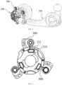
- FIG. 1 shows a perspective illustration of a trailer hitch according to the disclosure.
- the trailer hitch is provided with a tow hook 100, an actuating device 200 connected to the tow hook in a torque-transmitting manner, and a locking member 300 for locking the tow hook 100.
- the tow hook 100 can be switched between a deployed position and a retracted position by means of the actuating device 200.
- the actuating device 200 is provided with a driver, a driving shaft, a transmission disk, and a driven shaft. Only the driven shaft is provided with a reference sign 210 for the sake of clarity.
- the driver can be configured as an electric motor, in particular a reversible electric motor, and its output shaft is connected to the driving shaft.
- the transmission disk is connected to the driving shaft in an assembled state and can rotate freely relative to the driven shaft 210, and the driven shaft 210 is connected to, and rotates in synchronism with, the tow hook 100.
- the transmission disk When the driving shaft drives the transmission disk to rotate freely to unlock or lock the movement of the driven shaft 210 and therefore the tow hook 100, the transmission disk is in a rotating state and the driven shaft 210 remains unrotated.
- the transmission disk When the trailer hitch is in use, the transmission disk is first driven to rotate freely by the driving shaft, the transmission disk drives the locking member 300 and the locking counterpart out of the locking state and thus releases the tow hook 100.
- the locking counterpart can be arranged at the driven shaft 210 or can be configured as part of the driven shaft 210 itself.
- the driving shaft then continues to rotate and the driven shaft 210 is driven to rotate by means of the transmission disk, and the rotation of the driven shaft drives the tow hook 100 to switch between the retracted position and the deployed position.
- the locking member 300 moves back into the locking state with the locking counterpart.
- This process can likewise be carried out by means of the actuating device 200 mentioned above.
- the driving shaft drives the transmission disk to reversely rotate freely and thus moves the locking member 300 into the locking state.
- the return of the locking member to the locking state can also be achieved by means of a restoring spring to which the locking member itself is assigned.
- the locking member completes an unlocking process and a locking process by means of the driver and the restoring spring, respectively.
- FIG. 2 for the unlocking state in which the locking member 300 is disengaged from the locking counterpart.
- FIG. 3 for the locking state in which the locking member 300 is in engagement with the locking counterpart.
- the locking counterpart can optionally be configured as a locking groove 211 at an outer circumference of the driven shaft 210.
- the locking groove is open in a direction away from the center of the driven shaft in order to receive the locking member 300.
- the actuating device 200 is also provided with a fixedly arranged connecting plate (not shown), and the locking member 300 can rotate about a pivot 310 fixed to the connecting plate so as to be engaged into the locking groove 211 or disengaged from the locking groove 211.
- free rotation of the transmission disk relates only to its action on the driven shaft, and during the free rotation the transmission disk can act as a driving mechanism for the locking member.
- the transmission disk can drive the locking member 300 received in a groove thereof (which for clarity can also be referred to as a driving groove) to move away from the locking groove 211 of the driven shaft.
- the locking member 300 may be configured as a sector plate, and correspondingly, the locking groove 211 of the driven shaft as the locking counterpart can be likewise configured as an arc-shaped groove, into which the locking member 300 can be rotated more smoothly and without impact.
- the locking member 300 and the locking counterpart can also be configured in the form of a jaw.
- the driven shaft 210 is configured to have a jaw on a sub-region of the outer circumference to engage with the locking member.
- the number of locking members can be equal to the number of locking counterparts, or the number of locking counterparts can be larger than, in particular a multiple of, the number of locking members.
- the driven shaft is provided with a plurality of locking counterparts, they can be arranged uniformly in a circumferential direction of the driven shaft.
- the configuration of the actuating device is not limited to the form explained above, and it can also be configured in any other possible forms.
- that locking member can be assigned to a special motor-type or mechanical-type driving structure, which can enable the movement of the locking member, for example by driving the pivot of the locking member. This will not be described in detail.
- the actuating device for driving the movement of the tow hook and a kinematic device between the actuating device and the tow hook are not limited to the forms mentioned above, but can be configured in any other possible forms. In other words, the free rotation between the components mentioned above is not mandatory.
- the actuating device can also have a driver and a corresponding transmission member in a conventional manner, which will not be described in detail.
- the trailer hitch according to the disclosure is also provided with a travel switch 400 which is not visible in FIG. 1 and which is assigned to the locking member or the locking counterpart described above. That is, each locking member or locking counterpart can be assigned to one travel switch, or a plurality of locking members or locking counterparts can be assigned to one travel switch, which is advantageous in particular in the case where a plurality of locking counterparts are arranged uniformly.
- the travel switch 400 includes a housing 410 and a shaft body 420.
- the shaft body is movably received in the housing 410 in an axial direction, which can be understood as a length direction of the shaft body 420.
- the travel switch is triggered by touching or pushing the shaft body 420 to give an electrical signal characterizing the movement of the locking member into position.
- the travel switch in addition to a first trigger mechanism 421 provided at the outward-facing end of the shaft body, the travel switch is provided with a second trigger structure 430 which is arranged movably (e.g., rollably).
- triggering of the travel switch 400 is implemented in such a way that the locking member 300 first touches the rollable second trigger structure 430 and immediately the first trigger structure 421 is pushed upward by the second trigger structure 430.
- the locking member is configured as a sector plate, a tangential impact generated by the locking member during triggering can be converted into rolling and upward movement of the second trigger structure. Thus, only an impact force in the axial direction is exerted on the first trigger structure.
- the intervention of the rolling friction pair can reduce the impact of the second trigger structure in direct contact and also better protect the first trigger structure of the shaft body. Furthermore, since the second trigger structure is easier to replace and less expensive than the first trigger structure of the shaft body, the travel switch according to the disclosure can reduce the maintenance frequency and maintenance costs to some extent.
- the second trigger structure 430 can be received in the housing 410 of the travel switch.
- an open receiving cavity is provided at an end of the housing, and the second trigger structure 430 is received in the receiving cavity and partially protrudes outward (to be precise, toward the exterior of the housing).
- partially protrudes means that the second trigger structure is not completely enclosed in the receiving cavity, but has a part protruding from the receiving cavity, so as to be touched by the locking member.
- a support structure having a circular hole segment can be provided at the end of the housing 410 to prevent the ball received in the housing from rolling out thereof.
- the second trigger structure 430 can rotate by 360° and translate in the axial direction in the housing 410.
- the travel switch 400 of this type can have its housing 410 directly fixed to the fixed connecting plate described above.
- the second trigger structure 430 can be assigned to a bracket 431.
- the bracket is fixed to the exterior of the travel switch 400, in particular surrounds the exterior of the housing 410.
- a groove is provided on a side of the bracket 431 facing the second trigger structure 430 for supporting the second trigger structure and preventing it from falling off.
- the groove can be configured to be circular and its diameter can be smaller than the diameter of the ball.
- the travel switch 400 of this type can be fixed to the fixed connecting plate described above by means of the bracket 430.
- the second trigger structure is not limited only to the spherical member mentioned above, it can also be configured as a specially-shaped member. A cam-like configuration, for example, is also possible.
- the application scenario of the travel switch according to the disclosure is not limited to the trailer hitch. The travel switch can also be used in other necessary devices or scenarios.
- the disclosure also relates to a vehicle having a trailer hitch according to the disclosure.
- the actuating device of the trailer hitch can be fixed to an impact beam of the vehicle.
Landscapes
- Engineering & Computer Science (AREA)
- Transportation (AREA)
- Mechanical Engineering (AREA)
- Vehicle Cleaning, Maintenance, Repair, Refitting, And Outriggers (AREA)
- Lock And Its Accessories (AREA)
- Switch Cases, Indication, And Locking (AREA)
Abstract
Description
- The disclosure relates to a travel switch, and a trailer hitch and a vehicle having such a travel switch.
- A trailer hitch for a vehicle typically includes a tow hook and a corresponding driving mechanism. The driving mechanism can be fixed to a vehicle body, for example to an impact beam of the vehicle. Depending on the requirements, the trailer hitch can be rotated by the driving mechanism to below the vehicle body and in a retracted position, or outside the vehicle body (e.g., behind the vehicle) for mounting, where the vehicle can be said to be in a deployed position. In order to prevent the trailer hitch from shaking during towing, the trailer hitch can also be equipped with a locking device for the tow hook, and a corresponding travel switch for detecting whether the locking device has reached a locking state.
- A travel switch for such a trailer hitch is known from the prior art, in which when moving into position, the locking device of the trailer hitch directly acts on a trigger structure of the travel switch and pushes a shaft body, which may result in damage to the trigger structure of the travel switch.
- According to various aspects, an objective of the disclosure is to provide an improved travel switch, and a trailer hitch and a vehicle having such a travel switch.
- In addition, the disclosure further aims to solve or alleviate other technical problems existing in the prior art.
- The disclosure solves the above problems by providing a travel switch, which specifically includes:
- a housing;
- a shaft body movably received in the housing in an axial direction and provided with a first trigger structure at an outward-facing end of the shaft body; and
- a second trigger structure movably arranged such that the first trigger structure is pushed via the second trigger structure to trigger the travel switch.
- In the travel switch provided according to an aspect of the disclosure, the second trigger structure is assigned to a bracket, the bracket being fixed to an exterior of the housing and having a groove on a side facing the second trigger structure, and the second trigger structure is arranged in the groove and protrudes partially toward the exterior of the housing.
- In the travel switch provided according to the aspect of the disclosure, an open receiving cavity is provided at an end of the housing, and the second trigger structure protrudes partially toward the exterior of the housing in the receiving cavity.
- In the travel switch provided according to the aspect of the disclosure, the second trigger structure is configured as a spherical member.
- In the travel switch provided according to the aspect of the disclosure, the second trigger structure is configured as a steel ball or a synthetic fiber ball.
- According to a further aspect of the disclosure, provided is a trailer hitch, which specifically includes:
- a tow hook;
- an actuating device connected to the tow hook and driving the tow hook to switch between a deployed position and a retracted position;
- a locking member movable relative to a locking counterpart of the actuating device for locking the tow hook and the actuating device in the deployed or retracted position; and
- a travel switch according to the disclosure as explained above for detecting whether the locking member and the locking counterpart have reached a locking state.
- In the trailer hitch provided according to the further aspect of the disclosure, the actuating device includes a driven shaft connected to the tow hook and a fixedly arranged connecting plate, wherein the locking counterpart is configured as a locking groove at an outer circumference of the driven shaft, and the locking member is rotatable into or away from the locking groove about a pivot fixed to the connecting plate.
- In the trailer hitch provided according to the further aspect of the disclosure, the locking member is configured as a sector plate, and the locking groove is configured as an arc-shaped groove matching the sector plate.
- In the trailer hitch provided according to the further aspect of the disclosure, the travel switch has its housing fixed to the connecting plate, or the travel switch is fixed to the connecting plate by means of a bracket for the second trigger structure.
- According to a still further aspect of the disclosure, provided is a vehicle having such a trailer hitch, which will not be described in detail.
- By providing the second trigger structure, the travel switch according to the disclosure can provide protection for the trigger structure of the shaft body, thereby reducing the maintenance frequency of the travel switch.
- The above and other features of the disclosure will become apparent with reference to accompanying drawings, in which:
-
FIG. 1 shows a perspective view of a trailer hitch according to the disclosure; -
FIG. 2 shows a partial view of the trailer hitch in an unlocking state; -
FIG. 3 shows a partial view of the trailer hitch in a locking state; and -
FIG. 4 shows a partial cross-sectional view of the trailer hitch in the locking state. - It is easy to understand that, according to the technical solutions of the disclosure, without changing the essential spirit of the disclosure, those of ordinary skill in the art can put forward various structures and implementations that can be replaced with each other. Therefore, the following detailed description and accompanying drawings are merely an exemplary illustration of the technical solutions of the disclosure, and should not be regarded as all of the disclosure or the restriction or limitation on the technical solutions of the disclosure.
- Orientation terms, such as up, down, left, right, front, rear, front side, back side, top, and bottom, which are or may be mentioned in this description, are defined with respect to the structures shown in the accompanying drawing, and are relative concepts, and therefore may correspondingly vary depending on different positions and different usage states. Therefore, these or other orientation terms should not be construed as restrictive terms as well. Moreover, the terms such as "first" "second", "third" or similar expressions are only used for description and distinction purposes, and should not be construed as indicating or implying the relative importance of corresponding members.
- With reference to
FIG. 1 , which shows a perspective illustration of a trailer hitch according to the disclosure. The trailer hitch is provided with atow hook 100, an actuatingdevice 200 connected to the tow hook in a torque-transmitting manner, and alocking member 300 for locking thetow hook 100. Thetow hook 100 can be switched between a deployed position and a retracted position by means of the actuatingdevice 200. - In one embodiment, the actuating
device 200 is provided with a driver, a driving shaft, a transmission disk, and a driven shaft. Only the driven shaft is provided with areference sign 210 for the sake of clarity. The driver can be configured as an electric motor, in particular a reversible electric motor, and its output shaft is connected to the driving shaft. The transmission disk is connected to the driving shaft in an assembled state and can rotate freely relative to the drivenshaft 210, and the drivenshaft 210 is connected to, and rotates in synchronism with, thetow hook 100. - When the driving shaft drives the transmission disk to rotate freely to unlock or lock the movement of the driven
shaft 210 and therefore thetow hook 100, the transmission disk is in a rotating state and the drivenshaft 210 remains unrotated. When the trailer hitch is in use, the transmission disk is first driven to rotate freely by the driving shaft, the transmission disk drives thelocking member 300 and the locking counterpart out of the locking state and thus releases thetow hook 100. The locking counterpart can be arranged at the drivenshaft 210 or can be configured as part of the drivenshaft 210 itself. The driving shaft then continues to rotate and the drivenshaft 210 is driven to rotate by means of the transmission disk, and the rotation of the driven shaft drives thetow hook 100 to switch between the retracted position and the deployed position. Finally, upon reaching the retracted or deployed position (that is, when the tow hook or the driven shaft is rotated into position), thelocking member 300 moves back into the locking state with the locking counterpart. This process can likewise be carried out by means of the actuatingdevice 200 mentioned above. Specifically, the driving shaft drives the transmission disk to reversely rotate freely and thus moves thelocking member 300 into the locking state. Furthermore, the return of the locking member to the locking state can also be achieved by means of a restoring spring to which the locking member itself is assigned. In this case, the locking member completes an unlocking process and a locking process by means of the driver and the restoring spring, respectively. Reference can be made toFIG. 2 for the unlocking state in which thelocking member 300 is disengaged from the locking counterpart. Reference can be made toFIG. 3 for the locking state in which thelocking member 300 is in engagement with the locking counterpart. - Here, the locking counterpart can optionally be configured as a
locking groove 211 at an outer circumference of the drivenshaft 210. The locking groove is open in a direction away from the center of the driven shaft in order to receive thelocking member 300. In addition, the actuatingdevice 200 is also provided with a fixedly arranged connecting plate (not shown), and thelocking member 300 can rotate about apivot 310 fixed to the connecting plate so as to be engaged into thelocking groove 211 or disengaged from thelocking groove 211. - It should be noted here that "free rotation" of the transmission disk relates only to its action on the driven shaft, and during the free rotation the transmission disk can act as a driving mechanism for the locking member. For example, during the free rotation, the transmission disk can drive the
locking member 300 received in a groove thereof (which for clarity can also be referred to as a driving groove) to move away from thelocking groove 211 of the driven shaft. - Optionally, the
locking member 300 may be configured as a sector plate, and correspondingly, thelocking groove 211 of the driven shaft as the locking counterpart can be likewise configured as an arc-shaped groove, into which thelocking member 300 can be rotated more smoothly and without impact. - Optionally, the locking
member 300 and the locking counterpart can also be configured in the form of a jaw. Specifically, the drivenshaft 210 is configured to have a jaw on a sub-region of the outer circumference to engage with the locking member. - Here, the number of locking members can be equal to the number of locking counterparts, or the number of locking counterparts can be larger than, in particular a multiple of, the number of locking members. Where the driven shaft is provided with a plurality of locking counterparts, they can be arranged uniformly in a circumferential direction of the driven shaft.
- It should be noted that the configuration of the actuating device is not limited to the form explained above, and it can also be configured in any other possible forms. For example, that locking member can be assigned to a special motor-type or mechanical-type driving structure, which can enable the movement of the locking member, for example by driving the pivot of the locking member. This will not be described in detail.
- Furthermore, it should be noted that the actuating device for driving the movement of the tow hook and a kinematic device between the actuating device and the tow hook are not limited to the forms mentioned above, but can be configured in any other possible forms. In other words, the free rotation between the components mentioned above is not mandatory. The actuating device can also have a driver and a corresponding transmission member in a conventional manner, which will not be described in detail.
- Furthermore, in order to detect whether the locking
member 300 and the locking counterpart (for example, the lockinggroove 211 in the figures) have reached the locking state, the trailer hitch according to the disclosure is also provided with atravel switch 400 which is not visible inFIG. 1 and which is assigned to the locking member or the locking counterpart described above. That is, each locking member or locking counterpart can be assigned to one travel switch, or a plurality of locking members or locking counterparts can be assigned to one travel switch, which is advantageous in particular in the case where a plurality of locking counterparts are arranged uniformly. - Referring to
FIG. 4 , which shows thetravel switch 400 and the lockingmember 300 in the locking state in a partially cross-sectional view, thetravel switch 400 according to the disclosure includes ahousing 410 and ashaft body 420. The shaft body is movably received in thehousing 410 in an axial direction, which can be understood as a length direction of theshaft body 420. For thetravel switch 400, the travel switch is triggered by touching or pushing theshaft body 420 to give an electrical signal characterizing the movement of the locking member into position. - According to the disclosure, in addition to a
first trigger mechanism 421 provided at the outward-facing end of the shaft body, the travel switch is provided with asecond trigger structure 430 which is arranged movably (e.g., rollably). Here, triggering of thetravel switch 400 is implemented in such a way that the lockingmember 300 first touches the rollablesecond trigger structure 430 and immediately thefirst trigger structure 421 is pushed upward by thesecond trigger structure 430. In particular, as shown in the figures, where the locking member is configured as a sector plate, a tangential impact generated by the locking member during triggering can be converted into rolling and upward movement of the second trigger structure. Thus, only an impact force in the axial direction is exerted on the first trigger structure. Instead of a lateral impact of the locking member on the first trigger structure, the intervention of the rolling friction pair can reduce the impact of the second trigger structure in direct contact and also better protect the first trigger structure of the shaft body. Furthermore, since the second trigger structure is easier to replace and less expensive than the first trigger structure of the shaft body, the travel switch according to the disclosure can reduce the maintenance frequency and maintenance costs to some extent. - Optionally, the
second trigger structure 430 is configured as a spherical member or a ball, which can be made of a high-strength material that is resistant to wear. For example, thesecond trigger structure 430 can be configured as a steel ball, a synthetic fiber ball, or a nylon ball. - Optionally, the
second trigger structure 430 can be received in thehousing 410 of the travel switch. In particular, an open receiving cavity is provided at an end of the housing, and thesecond trigger structure 430 is received in the receiving cavity and partially protrudes outward (to be precise, toward the exterior of the housing). Herein, by "partially protrudes" means that the second trigger structure is not completely enclosed in the receiving cavity, but has a part protruding from the receiving cavity, so as to be touched by the locking member. - In a configuration of the second trigger structure as a ball, a support structure having a circular hole segment can be provided at the end of the
housing 410 to prevent the ball received in the housing from rolling out thereof. Thesecond trigger structure 430 can rotate by 360° and translate in the axial direction in thehousing 410. In addition, thetravel switch 400 of this type can have itshousing 410 directly fixed to the fixed connecting plate described above. - Optionally, as shown in the figures, the
second trigger structure 430 can be assigned to abracket 431. The bracket is fixed to the exterior of thetravel switch 400, in particular surrounds the exterior of thehousing 410. A groove is provided on a side of thebracket 431 facing thesecond trigger structure 430 for supporting the second trigger structure and preventing it from falling off. In an embodiment in which the second trigger structure is configured as a ball, the groove can be configured to be circular and its diameter can be smaller than the diameter of the ball. In addition, thetravel switch 400 of this type can be fixed to the fixed connecting plate described above by means of thebracket 430. - Furthermore, it should be noted that the second trigger structure is not limited only to the spherical member mentioned above, it can also be configured as a specially-shaped member. A cam-like configuration, for example, is also possible. In addition, the application scenario of the travel switch according to the disclosure is not limited to the trailer hitch. The travel switch can also be used in other necessary devices or scenarios.
- Finally, the disclosure also relates to a vehicle having a trailer hitch according to the disclosure. The actuating device of the trailer hitch can be fixed to an impact beam of the vehicle.
- It should be understood that all of the above preferred embodiments are exemplary rather than limiting, and any modification or variation made by those skilled in the art to the specific embodiments described above without departing from the concept of the disclosure shall fall within the scope of legal protection of the disclosure.
Claims (10)
- A travel switch, comprisinga housing;a shaft body movably received in the housing in an axial direction and provided with a first trigger structure at an outward-facing end of the shaft body; anda second trigger structure movably arranged such that the first trigger structure is pushed via the second trigger structure to trigger the travel switch.
- The travel switch according to claim 1, wherein the second trigger structure is assigned to a bracket, the bracket being fixed to an exterior of the housing and having a groove on a side facing the second trigger structure, and the second trigger structure is arranged in the groove and protrudes partially toward the exterior of the housing.
- The travel switch according to claim 1, wherein an open receiving cavity is provided at an end of the housing, and the second trigger structure protrudes partially toward the exterior of the housing in the receiving cavity.
- The travel switch according to any one of claims 1 to 3, wherein the second trigger structure is configured as a spherical member.
- The travel switch according to claim 4, wherein the second trigger structure is configured as a steel ball or a synthetic fiber ball.
- A trailer hitch, comprising:a tow hook;an actuating device connected to the tow hook and driving the tow hook to switch between a deployed position and a retracted position;a locking member movable relative to a locking counterpart of the actuating device for locking the tow hook and the actuating device in the deployed or retracted position; anda travel switch according to any one of claims 1 to 5 for detecting whether the locking member and the locking counterpart have reached a locking state.
- The trailer hitch according to claim 6, wherein the actuating device comprises a driven shaft connected to the tow hook and a fixedly arranged connecting plate, wherein the locking counterpart is configured as a locking groove at an outer circumference of the driven shaft, and the locking member is rotatable into or away from the locking groove about a pivot fixed to the connecting plate.
- The trailer hitch according to claim 7, wherein the locking member is configured as a sector plate, and the locking groove is configured as an arc-shaped groove matching the sector plate.
- The trailer hitch according to claim 7, wherein the travel switch has its housing fixed to the connecting plate, or the travel switch is fixed to the connecting plate by means of a bracket for the second trigger structure.
- A vehicle, comprising a trailer hitch according to any one of claims 6 to 9.
Applications Claiming Priority (2)
| Application Number | Priority Date | Filing Date | Title |
|---|---|---|---|
| CN202220731803.4U CN217588723U (en) | 2022-03-31 | 2022-03-31 | Travel switch, trailer coupler and vehicle |
| PCT/CN2022/140257 WO2023185117A1 (en) | 2022-03-31 | 2022-12-20 | Travel switch, trailer hitch, and vehicle |
Publications (2)
| Publication Number | Publication Date |
|---|---|
| EP4503075A1 true EP4503075A1 (en) | 2025-02-05 |
| EP4503075A4 EP4503075A4 (en) | 2026-03-04 |
Family
ID=83540992
Family Applications (1)
| Application Number | Title | Priority Date | Filing Date |
|---|---|---|---|
| EP22934933.7A Pending EP4503075A4 (en) | 2022-03-31 | 2022-12-20 | TRAVEL SWITCH, TRAILER HITCH AND VEHICLE |
Country Status (3)
| Country | Link |
|---|---|
| EP (1) | EP4503075A4 (en) |
| CN (1) | CN217588723U (en) |
| WO (1) | WO2023185117A1 (en) |
Cited By (1)
| Publication number | Priority date | Publication date | Assignee | Title |
|---|---|---|---|---|
| EP4509334A4 (en) * | 2022-04-12 | 2026-03-04 | Nio Technology Anhui Co Ltd | Fixing plate assembly, tow hook, and vehicle |
Families Citing this family (1)
| Publication number | Priority date | Publication date | Assignee | Title |
|---|---|---|---|---|
| CN217588723U (en) * | 2022-03-31 | 2022-10-14 | 蔚来汽车科技(安徽)有限公司 | Travel switch, trailer coupler and vehicle |
Family Cites Families (12)
| Publication number | Priority date | Publication date | Assignee | Title |
|---|---|---|---|---|
| DE19711535C2 (en) * | 1997-03-20 | 2003-07-17 | Jaeger Cartronix Gmbh | Motorized trailer hitch for motor vehicles |
| DE102006008837A1 (en) * | 2006-02-27 | 2007-09-06 | Westfalia-Automotive Gmbh | Towbar for motor vehicles |
| CN204270921U (en) * | 2015-01-09 | 2015-04-15 | 南通昌荣机电有限公司 | a travel switch |
| DE102015204902A1 (en) * | 2015-03-18 | 2016-09-22 | Zf Friedrichshafen Ag | Ball pivot module and method for operating a ball pivot module |
| CZ308583B6 (en) * | 2017-01-20 | 2020-12-16 | Vapos, Spol. S R.O. | Automatic tilting towing device, especially for passenger cars |
| CN207474313U (en) * | 2017-11-10 | 2018-06-08 | 温州市黎东眼镜有限公司 | A kind of travel switch |
| CN209535063U (en) * | 2019-03-07 | 2019-10-25 | 中车青岛四方车辆研究所有限公司 | Position feedback component, switching mechanism and rail vehicle |
| CN113156533B (en) * | 2021-04-07 | 2024-12-24 | 安徽合力股份有限公司 | End induction device |
| CN215731366U (en) * | 2021-06-23 | 2022-02-01 | 天津盈科卓控科技有限公司 | Cylindrical travel switch |
| CN113580856A (en) * | 2021-07-26 | 2021-11-02 | 浙江致优汽车科技有限公司 | Trailer coupler with good mounting performance |
| CN215904262U (en) * | 2021-09-15 | 2022-02-25 | 精诚工科汽车系统有限公司 | Traction device for vehicle and vehicle |
| CN217588723U (en) * | 2022-03-31 | 2022-10-14 | 蔚来汽车科技(安徽)有限公司 | Travel switch, trailer coupler and vehicle |
-
2022
- 2022-03-31 CN CN202220731803.4U patent/CN217588723U/en active Active
- 2022-12-20 EP EP22934933.7A patent/EP4503075A4/en active Pending
- 2022-12-20 WO PCT/CN2022/140257 patent/WO2023185117A1/en not_active Ceased
Cited By (1)
| Publication number | Priority date | Publication date | Assignee | Title |
|---|---|---|---|---|
| EP4509334A4 (en) * | 2022-04-12 | 2026-03-04 | Nio Technology Anhui Co Ltd | Fixing plate assembly, tow hook, and vehicle |
Also Published As
| Publication number | Publication date |
|---|---|
| CN217588723U (en) | 2022-10-14 |
| EP4503075A4 (en) | 2026-03-04 |
| WO2023185117A1 (en) | 2023-10-05 |
Similar Documents
| Publication | Publication Date | Title |
|---|---|---|
| CN108468801B (en) | Parking mechanism | |
| JP4249818B2 (en) | External rearview mirror | |
| EP0519115B1 (en) | Foldable outside rearview mirror | |
| JP4072111B2 (en) | Power equipment | |
| CN217588723U (en) | Travel switch, trailer coupler and vehicle | |
| EP3630548B1 (en) | Drive mechanism and rear view device | |
| EP4707001A2 (en) | Self-lockable electric trailer hitching apparatus | |
| KR20120068957A (en) | Arrangement for attaching a modular clutch device on a driven shaft | |
| CN215752068U (en) | Armrest locking device | |
| CZ201330A3 (en) | Apparatus for lifting and lowering a lid pivotally connected to a frame, especially a car boot lid | |
| KR20250170535A (en) | Rotation stop device | |
| WO2000041914A1 (en) | A mirror rotation mechanism | |
| JPS6328579A (en) | Motor drive type hammer | |
| JP3536041B2 (en) | Shift lever device for vehicles | |
| KR102636548B1 (en) | Parking apparatus for vehicle | |
| CN219312663U (en) | Vehicle blind area video recorder | |
| CN204055601U (en) | Non-blind zone automobile--Radar Control System | |
| CN220122723U (en) | Outer rotor motor and robot joint | |
| CN222905516U (en) | Electric connection self-locking mechanism | |
| US3881325A (en) | Override clutch | |
| JP4087735B2 (en) | Vehicle lock device | |
| US7963560B2 (en) | Pivoting device for a centrifugal traction assembly of a vehicle | |
| JP2017523078A (en) | Anti-theft device for automobile | |
| JPH0986277A (en) | Motor-driven containing type door mirror | |
| JP3004709U (en) | Car door mirror |
Legal Events
| Date | Code | Title | Description |
|---|---|---|---|
| STAA | Information on the status of an ep patent application or granted ep patent |
Free format text: STATUS: THE INTERNATIONAL PUBLICATION HAS BEEN MADE |
|
| PUAI | Public reference made under article 153(3) epc to a published international application that has entered the european phase |
Free format text: ORIGINAL CODE: 0009012 |
|
| STAA | Information on the status of an ep patent application or granted ep patent |
Free format text: STATUS: REQUEST FOR EXAMINATION WAS MADE |
|
| 17P | Request for examination filed |
Effective date: 20241030 |
|
| AK | Designated contracting states |
Kind code of ref document: A1 Designated state(s): AL AT BE BG CH CY CZ DE DK EE ES FI FR GB GR HR HU IE IS IT LI LT LU LV MC ME MK MT NL NO PL PT RO RS SE SI SK SM TR |
|
| DAV | Request for validation of the european patent (deleted) | ||
| DAX | Request for extension of the european patent (deleted) | ||
| A4 | Supplementary search report drawn up and despatched |
Effective date: 20260130 |
|
| RIC1 | Information provided on ipc code assigned before grant |
Ipc: H01H 3/16 20060101AFI20260126BHEP Ipc: B60D 1/04 20060101ALI20260126BHEP |