EP4503056A1 - Water level control system of pressure regulator of pressurized water reactor - Google Patents
Water level control system of pressure regulator of pressurized water reactor Download PDFInfo
- Publication number
- EP4503056A1 EP4503056A1 EP22938283.3A EP22938283A EP4503056A1 EP 4503056 A1 EP4503056 A1 EP 4503056A1 EP 22938283 A EP22938283 A EP 22938283A EP 4503056 A1 EP4503056 A1 EP 4503056A1
- Authority
- EP
- European Patent Office
- Prior art keywords
- water level
- pressurizer
- setting value
- module
- control system
- Prior art date
- Legal status (The legal status is an assumption and is not a legal conclusion. Google has not performed a legal analysis and makes no representation as to the accuracy of the status listed.)
- Granted
Links
Images


Classifications
-
- G—PHYSICS
- G21—NUCLEAR PHYSICS; NUCLEAR ENGINEERING
- G21D—NUCLEAR POWER PLANT
- G21D3/00—Control of nuclear power plant
- G21D3/08—Regulation of any parameters in the plant
- G21D3/12—Regulation of any parameters in the plant by adjustment of the reactor in response only to changes in engine demand
- G21D3/14—Varying flow of coolant
-
- G—PHYSICS
- G21—NUCLEAR PHYSICS; NUCLEAR ENGINEERING
- G21C—NUCLEAR REACTORS
- G21C1/00—Reactor types
- G21C1/04—Thermal reactors ; Epithermal reactors
- G21C1/06—Heterogeneous reactors, i.e. in which fuel and moderator are separated
- G21C1/08—Heterogeneous reactors, i.e. in which fuel and moderator are separated moderator being highly pressurised, e.g. boiling water reactor, integral super-heat reactor, pressurised water reactor
- G21C1/086—Pressurised water reactors
-
- G—PHYSICS
- G21—NUCLEAR PHYSICS; NUCLEAR ENGINEERING
- G21C—NUCLEAR REACTORS
- G21C1/00—Reactor types
- G21C1/04—Thermal reactors ; Epithermal reactors
- G21C1/06—Heterogeneous reactors, i.e. in which fuel and moderator are separated
- G21C1/08—Heterogeneous reactors, i.e. in which fuel and moderator are separated moderator being highly pressurised, e.g. boiling water reactor, integral super-heat reactor, pressurised water reactor
- G21C1/09—Pressure regulating arrangements, i.e. pressurisers
-
- G—PHYSICS
- G21—NUCLEAR PHYSICS; NUCLEAR ENGINEERING
- G21C—NUCLEAR REACTORS
- G21C17/00—Monitoring; Testing ; Maintaining
- G21C17/02—Devices or arrangements for monitoring coolant or moderator
- G21C17/035—Moderator- or coolant-level detecting devices
-
- Y—GENERAL TAGGING OF NEW TECHNOLOGICAL DEVELOPMENTS; GENERAL TAGGING OF CROSS-SECTIONAL TECHNOLOGIES SPANNING OVER SEVERAL SECTIONS OF THE IPC; TECHNICAL SUBJECTS COVERED BY FORMER USPC CROSS-REFERENCE ART COLLECTIONS [XRACs] AND DIGESTS
- Y02—TECHNOLOGIES OR APPLICATIONS FOR MITIGATION OR ADAPTATION AGAINST CLIMATE CHANGE
- Y02E—REDUCTION OF GREENHOUSE GAS [GHG] EMISSIONS, RELATED TO ENERGY GENERATION, TRANSMISSION OR DISTRIBUTION
- Y02E30/00—Energy generation of nuclear origin
- Y02E30/30—Nuclear fission reactors
Definitions
- the invention relates to the field of nuclear power, and more particularly to a pressurizer water level control system of a pressurized water reactor.
- the pressurizer is an important device for controlling and protecting the pressure of the primary loop in a pressurized water reactor.
- the pressurizer is connected with the primary loop system through surge line piping, and a sprayer and an electric heater are arranged in the .pressurizer, When the reactor is running, the volume of coolant in the primary loop expands and contracts with the increase or decrease of power, thus causing the water level in the pressurizer to rise and fall.
- the steam can be condensed by spraying water to depressurize;
- the water can be heated by an electric heater to evaporate it, causing the steam density in the steam space to increase to boost the pressure, thereby adjusting the pressure of the entire system and enabling the pressurizer to effectively stabilize the system pressure.
- the pressurizer acts as a buffer tank for the primary loop coolant, compensating for changes in the water volume of the primary loop system.
- the pressurizer water level control system maintains the pressurizer water level at a setting value to ensure the pressure regulation characteristics of the pressurizer.
- the pressurizer water level control in a pressurized water reactor nuclear power plant is realized by adjusting the charging flow rate or the discharge flow rate, and there are three modes:
- the discharge flow rate is unchanged, and the charging flow rate is adjusted by adjusting the opening of the charge valve, so as to achieve the purpose of controlling the water level of the pressurizer;
- the charging flow level is unchanged, and the discharge flow rate is adjusted by adjusting the opening of the discharge valve, so as to achieve the purpose of controlling the water level of the pressurizer;
- a technical problem to be solved by the present invention is to provide a pressurizer water level control system of a pressurized water reactor in view of the above-described drawbacks of the prior art.
- a pressurizer water level control system of a pressurized water reactor is constructed, which comprises a heat exchanger, a primary loop system, a temperature measuring module, a water level setting value generating module, a pressurizer, a water level measuring device, a rotational speed control module and a charging pump;
- the heat exchanger is communicated with the primary loop system through a charging channel and a discharge channel, respectively;
- the temperature measuring module respectively measures the temperatures of the cold leg and the hot leg of the primary loop system, and obtains an average temperature of the primary loop system,
- the temperature measuring module is communicatively connected with the water level setting value generating module, and the water level setting value generating module generates a water level setting value Lref of the pressurizer according to the average temperature;
- the water level measuring device detects a real-time water level value of the pressurizer
- the rotational speed control module generates a control command for controlling the rotational speed of the charging pump according to the water level setting value and the real-time water level value.
- the charging pump is provided in the charging channel to supply water to the primary loop system, and the charging pump controls the water supply speed according to the control command.
- the cold leg temperature measuring unit, the hot leg temperature measuring unit are contact thermometers or infrared thermometers.
- the water level deviation range module comprises a water level detector.
- the charging pump is set to three rotational speeds R0, R1, R2, and R0 ⁇ R1 ⁇ R2;
- the charging pump keeps the rotational speed of R1 unchanged;
- a discharge control mechanism is provided on the discharge channel, and when the water level setting value is within the range of -L1 to L1, the discharge control mechanism balances the flow balance of the charging channel and the discharge channel by adjusting the discharge control valve.
- the discharge control mechanism comprises a discharge control valve.
- ⁇ is a constant and less than 1.
- the rotational speed of the charging pump is switched back to the medium rotational speed R1, and ⁇ is a constant and less than 1.
- a pressurizer water level control system of a pressurized water reactor comprises a heat exchanger, a primary loop system, a temperature measuring module, a water level setting value generating module, a pressurizer, a water level measuring device, and a charging pump 5.
- the primary loop system comprises a pressure vessel, a main pump, a primary side of the steam generator and corresponding piping, and further, the primary loop system comprises a cold leg 3 and a hot leg 4, respectively supplying the flow of cold water and hot water.
- the temperature measuring module measures the temperatures of the cold leg 3 and the hot leg 4 of the primary loop system respectively, and obtains the average temperature of the primary loop system.
- the temperature measuring module is communicatively connected to a water level setting value generating module, and the water level setting value generating module generates a water level setting value Lref of the pressurizer according to the average temperature.
- the water level measuring device detects the real-time water level value of the pressurizer, and the rotational speed control module generates a control command for controlling the rotational speed of the charging pump 5 according to the water level setting value and the real-time water level value.
- the charging pump 5 is provided in the charging channel 1 to supply water to the primary loop system, and the charging pump 5 controls the water supply speed according to the control command.
- the charging pump 5 as the actuating mechanism of the pressurizer water level control, the switching of different rotational speeds can be realized, and the water level deviation of the pressurizer allowed by operation is set, which can avoid frequent action of the actuating mechanism and ensure the adjustment accuracy.
- the pressurizer water level control system further comprises a water level deviation range module disposed between the water level setting value generating module and the rotational speed control module, and the water level deviation range module performs subtraction based on the real-time water level value and the water level setting value to generate a water level deviation signal.
- the charging pump 5 is set to three rotational speeds R0, R1, and R2, and R0 ⁇ R1 ⁇ R2, and the relationship between the rotational speed demand of the charging pump 5 and the deviation of the water level of the pressurizer is shown in FIG. 3 .
- the charging pump 5 keeps the rotational speed of R1 unchanged.
- the rotational speed of the charging pump 5 is switched to the rotational speed R0, and if the water level deviation gradually decreases until it is less than L1- ⁇ , the rotational speed of the charging pump 5 is switched back to the medium rotational speed R1, and ⁇ is a constant and less than 1, such as 0.1, 0.5, 0.9, etc.
- the rotational speed of the charging pump 5 is switched to the rotational speed R2, and further, if the water level deviation gradually increases until it is in the range greater than -L1 + ⁇ , the rotational speed of the charging pump 5 is switched back to the medium rotational speed R1, as above, ⁇ is a constant and less than 1, such as 0.1, 0.5, 0.9, etc.
- the discharge control mechanism 6 is provided on the discharge channel 2, and when the water level setting value is within the range of -L1 to L1, the discharge control mechanism 6 balances the flow of the charging channel 1 and the discharge channel 2, so that the water level of the pressurizer can be maintained near the setting value.
- the discharge control mechanism 6 comprises a discharge control valve, and the flow of the charging channel 1 and the discharge channel 2 is balanced by manually adjusting the discharge control valve.
- the discharge control mechanism 6 may also be an electrical control switch.
- a charging flow meter (not shown) is provided on the charging channel 1, and a discharge flow meter (not shown) is provided on the discharge channel 2.
- the charging flow rate and the discharge flow rate are not used in the water level control of the pressurizer according to the present invention, but are only used for monitoring.
- the water level signal of the pressurizer and the water level setting value of the pressurizer generated by the average temperature of the primary loop are sent to the rotational speed control module; After the rotational speed control module performs real-time calculation and processing, a rotational speed switching command of the charging pump 5 is generated and sent to the charging pump 5, and the charging flow rate is adjusted by the charging pump 5 to realize water level control of the pressurizer.
- the rotational speed control module of the charging pump 5 allows a certain deviation between the water level of the pressurizer and the setting value during normal operation of the reactor, and effectively avoids frequent operation of the charging pump 5.
- the rotational speed switching of the charging pump 5 can realize the rapid adjustment of the charging flow rate, so that the water level of the pressurizer can be quickly restored to the vicinity of the setting value.
- the actuating mechanism required by the present invention is the charging pump 5, and the charging pump 5 only needs to have three operating conditions, and each operating condition point has a corresponding main pump rotational speed and flow rate.
- the charging pump 5 is operated only at three working conditions, which greatly reduces the frequency conversion equipment of the charging pump 5 and is beneficial to saving the equipment space of the pressurized water reactor.
- the water level of the pressurizer is controlled by adjusting the charging flow rate and keeping the discharge flow rate unchanged.
- the water level setting value of the pressurizer is determined by the average temperature of the primary loop, the water level setting value of the pressurizer are input to the water level deviation range module, and the deviation between the measured water level value of the pressurizer and the setting value are input to the rotational speed control module of the charging pump 5 to generate the rotational speed signal of the charging pump 5, which is transmitted to the charging pump 5.
- the charging flow rate is changed by switching the rotational speed of the charging pump 5.
- An appropriate pressurizer water level control actuating mechanism and control system are adopted to meet the requirements of the pressurizer water level control of the pressurized water reactor.
Landscapes
- Physics & Mathematics (AREA)
- Engineering & Computer Science (AREA)
- Plasma & Fusion (AREA)
- General Engineering & Computer Science (AREA)
- High Energy & Nuclear Physics (AREA)
- Control Of Non-Electrical Variables (AREA)
- Control Of Positive-Displacement Pumps (AREA)
Abstract
Description
- The invention relates to the field of nuclear power, and more particularly to a pressurizer water level control system of a pressurized water reactor.
- The pressurizer is an important device for controlling and protecting the pressure of the primary loop in a pressurized water reactor. The pressurizer is connected with the primary loop system through surge line piping, and a sprayer and an electric heater are arranged in the .pressurizer, When the reactor is running, the volume of coolant in the primary loop expands and contracts with the increase or decrease of power, thus causing the water level in the pressurizer to rise and fall.
- When the pressure in the pressurizer increases as the liquid level increases, the steam can be condensed by spraying water to depressurize; When the pressure drops, the water can be heated by an electric heater to evaporate it, causing the steam density in the steam space to increase to boost the pressure, thereby adjusting the pressure of the entire system and enabling the pressurizer to effectively stabilize the system pressure.
- At the same time, the pressurizer acts as a buffer tank for the primary loop coolant, compensating for changes in the water volume of the primary loop system. The pressurizer water level control system maintains the pressurizer water level at a setting value to ensure the pressure regulation characteristics of the pressurizer.
- At present, the pressurizer water level control in a pressurized water reactor nuclear power plant is realized by adjusting the charging flow rate or the discharge flow rate, and there are three modes:
- 1, the discharge flow rate is unchanged, and the charging flow rate is adjusted by adjusting the opening of the charge valve, so as to achieve the purpose of controlling the water level of the pressurizer;
- 2, the charging flow level is unchanged, and the discharge flow rate is adjusted by adjusting the opening of the discharge valve, so as to achieve the purpose of controlling the water level of the pressurizer;
- 3. by stating-stopping the charging pump and opening-closing the discharge valve, the charging flow rate and the discharge flow rate are simultaneously adjusted to control the water level of the pressurizer.
- Disadvantages: The water level control logic of the pressurizer is complicated, the number of actuating mechanisms in the control system is large, and the equipment occupies a large space.
- A technical problem to be solved by the present invention is to provide a pressurizer water level control system of a pressurized water reactor in view of the above-described drawbacks of the prior art.
- The technical scheme adopted by the invention to solve the technical problem is that: a pressurizer water level control system of a pressurized water reactor is constructed, which comprises a heat exchanger, a primary loop system, a temperature measuring module, a water level setting value generating module, a pressurizer, a water level measuring device, a rotational speed control module and a charging pump;
- The heat exchanger is communicated with the primary loop system through a charging channel and a discharge channel, respectively;
- The temperature measuring module respectively measures the temperatures of the cold leg and the hot leg of the primary loop system, and obtains an average temperature of the primary loop system,
- The temperature measuring module is communicatively connected with the water level setting value generating module, and the water level setting value generating module generates a water level setting value Lref of the pressurizer according to the average temperature;
- The water level measuring device detects a real-time water level value of the pressurizer;
- The rotational speed control module generates a control command for controlling the rotational speed of the charging pump according to the water level setting value and the real-time water level value.
- The charging pump is provided in the charging channel to supply water to the primary loop system, and the charging pump controls the water supply speed according to the control command.
- In some embodiments, the temperature measuring module comprises a cold leg temperature measuring unit disposed on the cold leg, and a hot leg temperature measuring unit disposed on the hot leg.
- In some embodiments, the cold leg temperature measuring unit, the hot leg temperature measuring unit are contact thermometers or infrared thermometers.
- In some embodiments, the temperature measuring module further comprises an average temperature generating module, the average temperature generating module averages the measured temperature of the cold leg and measured temperature of the hot leg to generate an average temperature Tavg of the primary loop, wherein

- In some embodiments, the water level setting value generating module generates a water level setting value from a fitting relationship according to the average temperature of the primary loop:

- In some embodiments, the pressurizer water level control system further comprises a water level deviation range module disposed between the water level setting value generating module and the rotational speed control module, and the water level deviation range module generates a water level deviation signal by performing subtraction according to the real-time water level value and the water level setting value.
- In some embodiments, the relationship between a water level deviation range and a water level setting value of the pressurizer is as follows:

wherein: - L1 is the water level deviation range, and the unit is % range;
- Lref is the water level setting value of the pressurizer, and the unit is % range;
- C is a constant, and its value ranges from 0 to 1.
- In some embodiments, the water level deviation range module comprises a water level detector.
- In some embodiments, the charging pump is set to three rotational speeds R0, R1, R2, and R0 < R1 < R2;
- When the water level setting value is in the range of -L1 to L1, the charging pump keeps the rotational speed of R1 unchanged;
- When the water level deviation of the pressurizer is greater than L1, the rotational speed of the charging pump is switched to the rotational speed R0,
- When the water level deviation of the pressurizer is less than-L1, the rotational speed of the charging pump is switched to the rotational speed R2.
- In some embodiments, a discharge control mechanism is provided on the discharge channel, and when the water level setting value is within the range of -L1 to L1, the discharge control mechanism balances the flow balance of the charging channel and the discharge channel by adjusting the discharge control valve.
- In some embodiments, the discharge control mechanism comprises a discharge control valve.
- In some embodiments, if the water level deviation gradually decreases until it is less than the range L1-ε, the rotational speed of the charging pump is switched back to the medium rotational speed R1, ε is a constant and less than 1.
- In some embodiments, if the water level deviation gradually increases until it is greater than-L1 + ε, the rotational speed of the charging pump is switched back to the medium rotational speed R1, and ε is a constant and less than 1.
- The pressurizer water level control system of the pressurized water reactor according to the present invention has the following beneficial effects: the charging pump is adopted as the actuating mechanism of the pressurizer water level control, the switching of different rotational speeds can be realized, and the water level deviation of the pressurizer allowed by operation is set, and the regulation accuracy can be guaranteed while avoiding the frequent action of the actuating mechanism.
- The present invention will be further described below with reference to the accompanying drawings and examples, in which:
-
FIG. 1 is a schematic diagram of a pressurizer water level control system of a pressurized water reactor according to an embodiment of the present invention; -
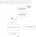
FIG. 2 is a schematic diagram of the process of pressurizer water level control; -
FIG. 3 is a functional graph of the rotational speed control of a charging pump. - In order to have a clearer understanding of the technical features, objects and effects of the present invention, specific embodiments of the present invention will now be described in detail with reference to the accompanying drawings.
- As shown in
FIG. 1 , a pressurizer water level control system of a pressurized water reactor according to a preferred embodiment of the present invention comprises a heat exchanger, a primary loop system, a temperature measuring module, a water level setting value generating module, a pressurizer, a water level measuring device, and a charging pump 5. - As shown in
FIG. 1 andFIG. 2 , the heat exchanger is communicated with the RCV(Chemical and Volume Control System), and the heat exchanger is communicated with the primary loop system through a charging channel 1 and a discharge channel 2, respectively, and the charging channel 1 supplies water to the primary loop system and replenishes water into the pressurizer. The water in the primary loop system flows out through the discharge channel 2, lowering the water level of the pressurizer. - The primary loop system comprises a pressure vessel, a main pump, a primary side of the steam generator and corresponding piping, and further, the primary loop system comprises a cold leg 3 and a hot leg 4, respectively supplying the flow of cold water and hot water. The temperature measuring module measures the temperatures of the cold leg 3 and the hot leg 4 of the primary loop system respectively, and obtains the average temperature of the primary loop system.
- The temperature measuring module is communicatively connected to a water level setting value generating module, and the water level setting value generating module generates a water level setting value Lref of the pressurizer according to the average temperature.
- The water level measuring device detects the real-time water level value of the pressurizer, and the rotational speed control module generates a control command for controlling the rotational speed of the charging pump 5 according to the water level setting value and the real-time water level value.
- The charging pump 5 is provided in the charging channel 1 to supply water to the primary loop system, and the charging pump 5 controls the water supply speed according to the control command.
- By adopting the charging pump 5 as the actuating mechanism of the pressurizer water level control, the switching of different rotational speeds can be realized, and the water level deviation of the pressurizer allowed by operation is set, which can avoid frequent action of the actuating mechanism and ensure the adjustment accuracy.
- In some embodiments, the temperature measuring module comprises a cold leg temperature measuring unit disposed on the cold leg 3, and a hot leg temperature measuring unit disposed on the hot leg 4. Generally, the cold leg temperature measuring unit and the hot leg temperature measuring unit are contact thermometers or infrared thermometers, and thermometers are respectively arranged in the cold leg 3 and the hot leg 4 of the primary loop for measuring the temperatures of the cold leg 3 and the hot leg 4 of the primary loop, thereby obtaining an average temperature.
- Further, the temperature measuring module further comprises an average temperature generating module, and the average temperature generating module averages the measured temperature of the cold leg 3 and the measured temperature of the hot leg 4 to generate an average temperature Tavg of the primary loop, wherein

- In other embodiments, the average temperature generating module may also multiply one of the temperature of the cold leg 3 and the temperature of the hot leg 4 by a coefficient, and then add to the other and average it.
- Preferably, the water level setting value generating module generates the water level setting value of the pressurizer according to the average temperature of the primary loop from the fitting relationship equation Lref=f (Tavg).
- In some embodiments, the pressurizer water level control system further comprises a water level deviation range module disposed between the water level setting value generating module and the rotational speed control module, and the water level deviation range module performs subtraction based on the real-time water level value and the water level setting value to generate a water level deviation signal.
- Further, the relationship between the water level deviation range and the water level setting value of the pressurizer is as follows:

wherein: - L1 is the water level deviation range, and the unit is% range;
- Lref is the water level setting value of the pressurizer, and the unit is% range;
- C is a constant, and the value ranges from 0 to 1. C can be set according to the actual situation, such as 0.1, 0.5, 0.9, 1, etc.
- In some embodiments, the water level deviation range module comprises a water level detector for detecting a real-time water level value of the water level, performing subtraction according to the real-time water level value and the water level setting value to generate a water level deviation signal, and the present invention realizes the following functions by setting the water level deviation range signal:
- When the water level of the pressurizer is high, a larger deviation amount is set to allow a larger deviation, which is beneficial to avoid frequent action of the actuating mechanism when the water level is high;
- When the water level of the pressurizer is low, a reduced deviation amount is set to allow a small deviation, which is beneficial to improving the water level adjustment accuracy of the pressurizer and avoiding triggering of the protection signal due to the obvious deviation of the water level from the setting value.
- With reference to
FIG. 2 andFIG. 3 , further, in order to allow the charging pump 5 to adapt to the requirements of different charging amounts, the charging pump 5 is set to three rotational speeds R0, R1, and R2, and R0 < R1 < R2, and the relationship between the rotational speed demand of the charging pump 5 and the deviation of the water level of the pressurizer is shown inFIG. 3 . - During stable operation, that is, when the water level setting value is in the range of-L1 to L1, the charging pump 5 keeps the rotational speed of R1 unchanged.
- When the water level deviation of the pressurizer is greater than L1, the rotational speed of the charging pump 5 is switched to the rotational speed R0, and if the water level deviation gradually decreases until it is less than L1-ε, the rotational speed of the charging pump 5 is switched back to the medium rotational speed R1, and ε is a constant and less than 1, such as 0.1, 0.5, 0.9, etc.
- When the water level deviation of the pressurizer is less than -L1, the rotational speed of the charging pump 5 is switched to the rotational speed R2, and further, if the water level deviation gradually increases until it is in the range greater than -L1 + ε, the rotational speed of the charging pump 5 is switched back to the medium rotational speed R1, as above, ε is a constant and less than 1, such as 0.1, 0.5, 0.9, etc.
- Preferably, the discharge control mechanism 6 is provided on the discharge channel 2, and when the water level setting value is within the range of -L1 to L1, the discharge control mechanism 6 balances the flow of the charging channel 1 and the discharge channel 2, so that the water level of the pressurizer can be maintained near the setting value. In this embodiment, the discharge control mechanism 6 comprises a discharge control valve, and the flow of the charging channel 1 and the discharge channel 2 is balanced by manually adjusting the discharge control valve. In other embodiments, the discharge control mechanism 6 may also be an electrical control switch.
- Generally, a charging flow meter (not shown) is provided on the charging channel 1, and a discharge flow meter (not shown) is provided on the discharge channel 2. The charging flow rate and the discharge flow rate are not used in the water level control of the pressurizer according to the present invention, but are only used for monitoring.
- The water level signal of the pressurizer and the water level setting value of the pressurizer generated by the average temperature of the primary loop are sent to the rotational speed control module; After the rotational speed control module performs real-time calculation and processing, a rotational speed switching command of the charging pump 5 is generated and sent to the charging pump 5, and the charging flow rate is adjusted by the charging pump 5 to realize water level control of the pressurizer.
- According to the above description, the rotational speed control module of the charging pump 5 allows a certain deviation between the water level of the pressurizer and the setting value during normal operation of the reactor, and effectively avoids frequent operation of the charging pump 5.
- At the same time, when the water level deviation is large, the rotational speed switching of the charging pump 5 can realize the rapid adjustment of the charging flow rate, so that the water level of the pressurizer can be quickly restored to the vicinity of the setting value.
- The hysteresis ε is required to switch the speed of the charging pump 5 to avoid frequent switching of the speed of the charging pump 5 when the water level deviation Δ L of the pressurizer is near -L1 and L1. The charging pump 5 has three operating conditions, and can realize the adjustment of different charging flow rates.
- The actuating mechanism required by the present invention is the charging pump 5, and the charging pump 5 only needs to have three operating conditions, and each operating condition point has a corresponding main pump rotational speed and flow rate.
- The charging pump 5 is operated only at three working conditions, which greatly reduces the frequency conversion equipment of the charging pump 5 and is beneficial to saving the equipment space of the pressurized water reactor.
- The water level of the pressurizer is controlled by adjusting the charging flow rate and keeping the discharge flow rate unchanged. The water level setting value of the pressurizer is determined by the average temperature of the primary loop, the water level setting value of the pressurizer are input to the water level deviation range module, and the deviation between the measured water level value of the pressurizer and the setting value are input to the rotational speed control module of the charging pump 5 to generate the rotational speed signal of the charging pump 5, which is transmitted to the charging pump 5. The charging flow rate is changed by switching the rotational speed of the charging pump 5.
- An appropriate pressurizer water level control actuating mechanism and control system are adopted to meet the requirements of the pressurizer water level control of the pressurized water reactor.
- Advantages of the present invention:
- 1, The control system does not need to control the discharge regulating valve, and at the same time, the charging regulating valve is omitted, only the charging pump 5 serves as the actuating mechanism of the pressurizer water level control system, and the number of actuating mechanisms is reduced, such as reducing the configuration of the charging valve and the discharge valve, etc., the charging pump 5 has three operating conditions, reducing the frequency conversion equipment of the charging pump (5), which is beneficial to simplifying the equipment configuration;
- 2. Setting the water level deviation of the pressurizer allowed for operation is beneficial to avoid frequent action of the actuating mechanism and ensure the adjustment accuracy;
- 3. The invention does not need to set a PI controller, the control channel is more simplified, the water level control scheme of the pressurizer is simplified, the control setting value is reduced, and it is beneficial to simplify the debugging process.
- 4. The pressurizer water level control system allows a certain deviation between the water level and the setting value of the pressurizer during normal operation of the reactor (within the range of -L1 to L1). The control logic is relatively simple and requires few actuating mechanisms. It can be applied to the pressurizer water level control of the pressurized water reactor.
- It is understood that the above-described technical features can be used in any combination without limitation.
- The above description is merely an embodiment of the present invention, and does not limit the patent scope of the present invention accordingly. Any equivalent structure or equivalent flow transformation made by using the contents of the specification and drawings of the present invention, or directly or indirectly applied to other related technical fields, is also included within the patent protection scope of the present invention.
Claims (13)
- A pressurizer water level control system of a pressurized water reactor, which comprises a heat exchanger, a primary loop system, a temperature measuring module, a water level setting value generating module, a pressurizer, a water level measuring device, a rotational speed control module, and a charging pump (5);the heat exchanger is communicated with the primary loop system through a charging channel (1) and a discharge channel (2) respectively;the temperature measuring module respectively measures the temperatures of the cold leg (3) and the hot leg (4) of the primary loop system, and obtains the average temperature of the primary loop system;the temperature measuring module is communicatively connected with the water level setting value generating module, and the water level setting value generating module generates a water level setting value Lref of the pressurizer according to the average temperature;the water level measuring device detects a real-time water level value of the pressurizer;the rotational speed control module generates a control command for controlling the rotational speed of the charging pump (5) according to the water level setting value and the real-time water level value;the charging pump (5) is arranged in the charging channel (1) to supply water to the primary loop system, and the charging pump (5) controls the water supply speed according to the control command.
- The pressurizer water level control system of the pressurized water reactor according to claim 1, wherein the temperature measuring module comprises a cold leg temperature measuring unit arranged on the cold leg (3) and a hot leg temperature measuring unit arranged on the hot leg (4).
- The pressurizer water level control system of the pressurized water reactor according to claim 2, wherein the cold leg temperature measuring unit and the hot leg temperature measuring unit are contact thermometers or infrared thermometers.
- The pressurizer water level control system of the pressurized water reactor according to claim 2, wherein the temperature measuring module further comprises an average temperature generating module, and the average temperature generating module averages the measured temperature of the cold leg (3) and the measured temperature of the hot leg (4) to generate an average temperature Tavg of the primary loop, wherein

- The pressurizer water level control system of the pressurized water reactor according to claim 3, wherein the water level setting value generating module generates a pressurizer water level setting value by a fitting relationship according to the average temperature of the primary loop:

- The pressurizer water level control system of the pressurized water reactor according to any one of claims 1 to 5, wherein the pressurizer water level control system further comprises a water level deviation range module arranged between the water level setting value generating module and the rotational speed control module, and the water level deviation range module performs subtraction according to the real-time water level value and the water level setting value and generates a water level deviation signal.
- The pressurizer water level control system of the pressurized water reactor according to claim 6, wherein the relationship between a water level deviation range and a water level setting value of the pressurizer is as follows:
 L1 is the water level deviation range, and the unit is % range;Lref is the water level setting value of the pressurizer, and the unit is % range;C is a constant, and its value range is between 0 and 1.
 - The pressurizer water level control system of the pressurized water reactor according to claim 6, wherein the water level deviation range module comprises a water level detector.
- The pressurizer water level control system of the pressurized water reactor according to claim 7, wherein the charging pump (5) is set to three rotational speeds R0, R1, and R2, and R0 < R1 < R2;when the water level setting value is in the range of -L1 to L1, the charging pump (5) keeps the rotating speed of R1 unchanged;when the water level deviation of the pressurizer is greater than L1, the rotating speed of the charging pump (5) is switched to the rotating speed R0,when the water level deviation of the pressurizer is less than -L1, the rotating speed of the charging pump (5) is switched to the rotating speed R2.
- The pressurizer water level control system of the pressurized water reactor according to claim 9, wherein a discharge control mechanism (6) is provided on the discharge channel (2), and when the water level setting value is within the range of -L1 to L1, the discharge control mechanism (6) balances the flow balance of the charging channel (1) and the discharge channel (2).
- The pressurizer water level control system of the pressurized water reactor according to claim 10, wherein the discharge control mechanism (6) comprises a discharge control valve.
- The pressurizer water level control system of the pressurized water reactor according to claim 9, wherein if the water level deviation gradually decreases until it is less than L1-ε, the rotational speed of the charging pump (5) is switched back to the medium rotational speed R1, and ε is a constant and less than 1.
- The pressurizer water level control system of the pressurized water reactor according to claim 9, wherein if the water level deviation gradually increases until it is in a range greater than -L1 + ε, the rotational speed of the charging pump (5) is switched back to the medium rotational speed R1, and ε is a constant and less than 1.
Applications Claiming Priority (2)
| Application Number | Priority Date | Filing Date | Title |
|---|---|---|---|
| CN202210417514.1A CN114999698A (en) | 2022-04-20 | 2022-04-20 | Water level control system of pressure stabilizer of pressurized water reactor |
| PCT/CN2022/132994 WO2023202064A1 (en) | 2022-04-20 | 2022-11-18 | Water level control system of pressure regulator of pressurized water reactor |
Publications (3)
| Publication Number | Publication Date |
|---|---|
| EP4503056A1 true EP4503056A1 (en) | 2025-02-05 |
| EP4503056A4 EP4503056A4 (en) | 2025-07-09 |
| EP4503056B1 EP4503056B1 (en) | 2025-11-05 |
Family
ID=83024692
Family Applications (1)
| Application Number | Title | Priority Date | Filing Date |
|---|---|---|---|
| EP22938283.3A Active EP4503056B1 (en) | 2022-04-20 | 2022-11-18 | Pressurizer water level control system of pressurized water reactor |
Country Status (3)
| Country | Link |
|---|---|
| EP (1) | EP4503056B1 (en) |
| CN (1) | CN114999698A (en) |
| WO (1) | WO2023202064A1 (en) |
Families Citing this family (4)
| Publication number | Priority date | Publication date | Assignee | Title |
|---|---|---|---|---|
| CN114999698A (en) * | 2022-04-20 | 2022-09-02 | 中广核研究院有限公司 | Water level control system of pressure stabilizer of pressurized water reactor |
| CN116430912B (en) * | 2022-09-08 | 2025-12-19 | 中广核惠州核电有限公司 | Nuclear power unit reactor coolant system voltage stabilizer liquid level control method and system |
| CN115562372B (en) * | 2022-09-13 | 2025-03-28 | 中广核惠州核电有限公司 | Flange surface liquid level control method, system and primary circuit control system |
| CN115597010B (en) * | 2022-10-12 | 2024-12-13 | 中广核工程有限公司 | Method, system, device and storage medium for diagnosing breach position of chemical containment system |
Family Cites Families (13)
| Publication number | Priority date | Publication date | Assignee | Title |
|---|---|---|---|---|
| JP3535087B2 (en) * | 2000-10-04 | 2004-06-07 | 株式会社日立製作所 | Reactor water supply control device |
| JP5091727B2 (en) * | 2008-03-11 | 2012-12-05 | 日立Geニュークリア・エナジー株式会社 | Chemical decontamination method |
| CN101483078B (en) * | 2009-01-05 | 2012-01-04 | 中国广东核电集团有限公司 | Water level control method and system for a nuclear power plant and its steam generator |
| CN102543232B (en) * | 2011-10-24 | 2014-08-27 | 上海电力学院 | Combined method for controlling water level and pressure of voltage stabilizer for nuclear power plant of pressurized water reactor |
| US20140140466A1 (en) * | 2012-07-02 | 2014-05-22 | David W. Richardson | Semi Submersible Nuclear Power Plant and Multipurpose Platform |
| CN104282350B (en) * | 2014-08-05 | 2017-01-25 | 中国核电工程有限公司 | Control method for reducing false alarm of nuclear power station charging pump |
| JP6479406B2 (en) * | 2014-10-20 | 2019-03-06 | 三菱重工業株式会社 | Cooling equipment and nuclear equipment |
| CN104637557A (en) * | 2015-02-04 | 2015-05-20 | 广东电网有限责任公司电力科学研究院 | Feedforward-feedback composite control method and system for pressure and liquid level of nuclear power station voltage stabilizer |
| CN110118171B (en) * | 2019-04-15 | 2021-02-05 | 中广核研究院有限公司 | Device and method for adjusting rotating speed of steam-driven main feed pump of nuclear power station |
| CN112382427B (en) * | 2020-11-05 | 2024-03-29 | 中广核工程有限公司 | Liquid level control method and system for nuclear power plant evaporator |
| CN113552906A (en) * | 2021-06-30 | 2021-10-26 | 浙江浙大中控信息技术有限公司 | Method for intelligently controlling quick constant water level operation of drainage pump station |
| CN114251645B (en) * | 2021-11-15 | 2023-12-26 | 中广核研究院有限公司 | Steam generator water level control system and control method |
| CN114999698A (en) * | 2022-04-20 | 2022-09-02 | 中广核研究院有限公司 | Water level control system of pressure stabilizer of pressurized water reactor |
-
2022
- 2022-04-20 CN CN202210417514.1A patent/CN114999698A/en active Pending
- 2022-11-18 EP EP22938283.3A patent/EP4503056B1/en active Active
- 2022-11-18 WO PCT/CN2022/132994 patent/WO2023202064A1/en not_active Ceased
Also Published As
| Publication number | Publication date |
|---|---|
| CN114999698A (en) | 2022-09-02 |
| WO2023202064A1 (en) | 2023-10-26 |
| EP4503056B1 (en) | 2025-11-05 |
| EP4503056A4 (en) | 2025-07-09 |
Similar Documents
| Publication | Publication Date | Title |
|---|---|---|
| EP4503056B1 (en) | Pressurizer water level control system of pressurized water reactor | |
| TW300172B (en) | ||
| CN111525155B (en) | Bubbling humidification device and humidification method for fuel cell test system | |
| US8781057B2 (en) | Control system and method for pressurized water reactor (PWR) and PWR systems including same | |
| KR100584836B1 (en) | Water supply control system considering the differential pressure of water supply control valve in nuclear power plant and its control method | |
| JPH0549076B2 (en) | ||
| CN114934896A (en) | Water pump frequency conversion control method and system and ship | |
| JPH0566601B2 (en) | ||
| CN112162482A (en) | Intelligent combined optimization rectifying device and method suitable for complex flow field and application | |
| CN102983342B (en) | Automatic water supplementing method of fuel cell humidifier and device thereof | |
| US20060057446A1 (en) | Control of conductivity reduction within a fuel cell system | |
| CN211238399U (en) | Fuel cell coolant temperature monitoring device | |
| CN117026299A (en) | Temperature control method of electrolytic tank and electrolytic device | |
| WO2009005230A1 (en) | Multi-functional fluid automatic shipping system | |
| CN111584899B (en) | Control system of air-cooled fuel cell stack | |
| CN114939831A (en) | Temperature control system and temperature control method for cooling water and cutting fluid | |
| JP4038142B2 (en) | Reactor power controller | |
| CN115562372A (en) | Flange surface liquid level control method, system and primary loop control system | |
| CN207507472U (en) | A kind of polymer emulsion synthesis reaction system | |
| JP2814706B2 (en) | Fuel cell generator | |
| JP7596256B2 (en) | Hydrogen gas supply system and hydrogen gas supply method | |
| EP4560221A1 (en) | Improved stratification water heater | |
| CN116412951B (en) | Pressure testing method and apparatus for expansion tanks in closed-loop systems. | |
| CN220437752U (en) | Pure water test system and test device | |
| JP2710125B2 (en) | Control device for excess steam in steam separator of fuel cell |
Legal Events
| Date | Code | Title | Description |
|---|---|---|---|
| STAA | Information on the status of an ep patent application or granted ep patent |
Free format text: STATUS: THE INTERNATIONAL PUBLICATION HAS BEEN MADE |
|
| PUAI | Public reference made under article 153(3) epc to a published international application that has entered the european phase |
Free format text: ORIGINAL CODE: 0009012 |
|
| STAA | Information on the status of an ep patent application or granted ep patent |
Free format text: STATUS: REQUEST FOR EXAMINATION WAS MADE |
|
| 17P | Request for examination filed |
Effective date: 20241024 |
|
| AK | Designated contracting states |
Kind code of ref document: A1 Designated state(s): AL AT BE BG CH CY CZ DE DK EE ES FI FR GB GR HR HU IE IS IT LI LT LU LV MC ME MK MT NL NO PL PT RO RS SE SI SK SM TR |
|
| A4 | Supplementary search report drawn up and despatched |
Effective date: 20250610 |
|
| RIC1 | Information provided on ipc code assigned before grant |
Ipc: G21C 17/035 20060101ALI20250603BHEP Ipc: G21C 1/09 20060101ALI20250603BHEP Ipc: G21C 1/08 20060101ALI20250603BHEP Ipc: G21D 3/14 20060101ALI20250603BHEP Ipc: G21D 3/04 20060101AFI20250603BHEP |
|
| DAV | Request for validation of the european patent (deleted) | ||
| DAX | Request for extension of the european patent (deleted) | ||
| RIC1 | Information provided on ipc code assigned before grant |
Ipc: G21D 3/04 20060101AFI20250808BHEP Ipc: G21D 3/14 20060101ALI20250808BHEP Ipc: G21C 1/08 20060101ALI20250808BHEP Ipc: G21C 1/09 20060101ALI20250808BHEP Ipc: G21C 17/035 20060101ALI20250808BHEP |
|
| GRAP | Despatch of communication of intention to grant a patent |
Free format text: ORIGINAL CODE: EPIDOSNIGR1 |
|
| STAA | Information on the status of an ep patent application or granted ep patent |
Free format text: STATUS: GRANT OF PATENT IS INTENDED |
|
| GRAS | Grant fee paid |
Free format text: ORIGINAL CODE: EPIDOSNIGR3 |
|
| GRAA | (expected) grant |
Free format text: ORIGINAL CODE: 0009210 |
|
| STAA | Information on the status of an ep patent application or granted ep patent |
Free format text: STATUS: THE PATENT HAS BEEN GRANTED |
|
| INTG | Intention to grant announced |
Effective date: 20250919 |
|
| AK | Designated contracting states |
Kind code of ref document: B1 Designated state(s): AL AT BE BG CH CY CZ DE DK EE ES FI FR GB GR HR HU IE IS IT LI LT LU LV MC ME MK MT NL NO PL PT RO RS SE SI SK SM TR |
|
| REG | Reference to a national code |
Ref country code: CH Ref legal event code: F10 Free format text: ST27 STATUS EVENT CODE: U-0-0-F10-F00 (AS PROVIDED BY THE NATIONAL OFFICE) Effective date: 20251105 Ref country code: GB Ref legal event code: FG4D |
|
| REG | Reference to a national code |
Ref country code: DE Ref legal event code: R096 Ref document number: 602022024700 Country of ref document: DE |
|
| REG | Reference to a national code |
Ref country code: IE Ref legal event code: FG4D |
|
| PGFP | Annual fee paid to national office [announced via postgrant information from national office to epo] |
Ref country code: AT Payment date: 20260113 Year of fee payment: 4 |
|
| PGFP | Annual fee paid to national office [announced via postgrant information from national office to epo] |
Ref country code: FR Payment date: 20251230 Year of fee payment: 4 |
|
| REG | Reference to a national code |
Ref country code: NL Ref legal event code: MP Effective date: 20251105 |
|
| PG25 | Lapsed in a contracting state [announced via postgrant information from national office to epo] |
Ref country code: ES Free format text: LAPSE BECAUSE OF FAILURE TO SUBMIT A TRANSLATION OF THE DESCRIPTION OR TO PAY THE FEE WITHIN THE PRESCRIBED TIME-LIMIT Effective date: 20251105 |
|
| REG | Reference to a national code |
Ref country code: LT Ref legal event code: MG9D |
|
| PG25 | Lapsed in a contracting state [announced via postgrant information from national office to epo] |
Ref country code: NO Free format text: LAPSE BECAUSE OF FAILURE TO SUBMIT A TRANSLATION OF THE DESCRIPTION OR TO PAY THE FEE WITHIN THE PRESCRIBED TIME-LIMIT Effective date: 20260205 |
|
| PG25 | Lapsed in a contracting state [announced via postgrant information from national office to epo] |
Ref country code: AT Free format text: LAPSE BECAUSE OF FAILURE TO SUBMIT A TRANSLATION OF THE DESCRIPTION OR TO PAY THE FEE WITHIN THE PRESCRIBED TIME-LIMIT Effective date: 20251105 Ref country code: FI Free format text: LAPSE BECAUSE OF FAILURE TO SUBMIT A TRANSLATION OF THE DESCRIPTION OR TO PAY THE FEE WITHIN THE PRESCRIBED TIME-LIMIT Effective date: 20251105 Ref country code: HR Free format text: LAPSE BECAUSE OF FAILURE TO SUBMIT A TRANSLATION OF THE DESCRIPTION OR TO PAY THE FEE WITHIN THE PRESCRIBED TIME-LIMIT Effective date: 20251105 |
|
| REG | Reference to a national code |
Ref country code: AT Ref legal event code: MK05 Ref document number: 1855316 Country of ref document: AT Kind code of ref document: T Effective date: 20251105 |
|
| PG25 | Lapsed in a contracting state [announced via postgrant information from national office to epo] |
Ref country code: NL Free format text: LAPSE BECAUSE OF FAILURE TO SUBMIT A TRANSLATION OF THE DESCRIPTION OR TO PAY THE FEE WITHIN THE PRESCRIBED TIME-LIMIT Effective date: 20251105 |
|
| PG25 | Lapsed in a contracting state [announced via postgrant information from national office to epo] |
Ref country code: RS Free format text: LAPSE BECAUSE OF FAILURE TO SUBMIT A TRANSLATION OF THE DESCRIPTION OR TO PAY THE FEE WITHIN THE PRESCRIBED TIME-LIMIT Effective date: 20260205 |
|
| PG25 | Lapsed in a contracting state [announced via postgrant information from national office to epo] |
Ref country code: IS Free format text: LAPSE BECAUSE OF FAILURE TO SUBMIT A TRANSLATION OF THE DESCRIPTION OR TO PAY THE FEE WITHIN THE PRESCRIBED TIME-LIMIT Effective date: 20260305 |
|
| PG25 | Lapsed in a contracting state [announced via postgrant information from national office to epo] |
Ref country code: PT Free format text: LAPSE BECAUSE OF FAILURE TO SUBMIT A TRANSLATION OF THE DESCRIPTION OR TO PAY THE FEE WITHIN THE PRESCRIBED TIME-LIMIT Effective date: 20260305 |
|
| PGFP | Annual fee paid to national office [announced via postgrant information from national office to epo] |
Ref country code: CZ Payment date: 20251105 Year of fee payment: 4 |
|
| PG25 | Lapsed in a contracting state [announced via postgrant information from national office to epo] |
Ref country code: PL Free format text: LAPSE BECAUSE OF FAILURE TO SUBMIT A TRANSLATION OF THE DESCRIPTION OR TO PAY THE FEE WITHIN THE PRESCRIBED TIME-LIMIT Effective date: 20251105 |
|
| PG25 | Lapsed in a contracting state [announced via postgrant information from national office to epo] |
Ref country code: LV Free format text: LAPSE BECAUSE OF FAILURE TO SUBMIT A TRANSLATION OF THE DESCRIPTION OR TO PAY THE FEE WITHIN THE PRESCRIBED TIME-LIMIT Effective date: 20251105 |
|
| PG25 | Lapsed in a contracting state [announced via postgrant information from national office to epo] |
Ref country code: BG Free format text: LAPSE BECAUSE OF FAILURE TO SUBMIT A TRANSLATION OF THE DESCRIPTION OR TO PAY THE FEE WITHIN THE PRESCRIBED TIME-LIMIT Effective date: 20251105 |