EP4502993A1 - Optical display, seat, and vehicle - Google Patents
Optical display, seat, and vehicle Download PDFInfo
- Publication number
- EP4502993A1 EP4502993A1 EP23794992.0A EP23794992A EP4502993A1 EP 4502993 A1 EP4502993 A1 EP 4502993A1 EP 23794992 A EP23794992 A EP 23794992A EP 4502993 A1 EP4502993 A1 EP 4502993A1
- Authority
- EP
- European Patent Office
- Prior art keywords
- housing
- optical display
- positioning
- edge
- curved mirror
- Prior art date
- Legal status (The legal status is an assumption and is not a legal conclusion. Google has not performed a legal analysis and makes no representation as to the accuracy of the status listed.)
- Pending
Links
Images




Classifications
-
- G—PHYSICS
- G09—EDUCATION; CRYPTOGRAPHY; DISPLAY; ADVERTISING; SEALS
- G09F—DISPLAYING; ADVERTISING; SIGNS; LABELS OR NAME-PLATES; SEALS
- G09F9/00—Indicating arrangements for variable information in which the information is built-up on a support by selection or combination of individual elements
- G09F9/30—Indicating arrangements for variable information in which the information is built-up on a support by selection or combination of individual elements in which the desired character or characters are formed by combining individual elements
-
- B—PERFORMING OPERATIONS; TRANSPORTING
- B60—VEHICLES IN GENERAL
- B60K—ARRANGEMENT OR MOUNTING OF PROPULSION UNITS OR OF TRANSMISSIONS IN VEHICLES; ARRANGEMENT OR MOUNTING OF PLURAL DIVERSE PRIME-MOVERS IN VEHICLES; AUXILIARY DRIVES FOR VEHICLES; INSTRUMENTATION OR DASHBOARDS FOR VEHICLES; ARRANGEMENTS IN CONNECTION WITH COOLING, AIR INTAKE, GAS EXHAUST OR FUEL SUPPLY OF PROPULSION UNITS IN VEHICLES
- B60K35/00—Instruments specially adapted for vehicles; Arrangement of instruments in or on vehicles
- B60K35/20—Output arrangements, i.e. from vehicle to user, associated with vehicle functions or specially adapted therefor
- B60K35/21—Output arrangements, i.e. from vehicle to user, associated with vehicle functions or specially adapted therefor using visual output, e.g. blinking lights or matrix displays
- B60K35/22—Display screens
-
- B—PERFORMING OPERATIONS; TRANSPORTING
- B60—VEHICLES IN GENERAL
- B60K—ARRANGEMENT OR MOUNTING OF PROPULSION UNITS OR OF TRANSMISSIONS IN VEHICLES; ARRANGEMENT OR MOUNTING OF PLURAL DIVERSE PRIME-MOVERS IN VEHICLES; AUXILIARY DRIVES FOR VEHICLES; INSTRUMENTATION OR DASHBOARDS FOR VEHICLES; ARRANGEMENTS IN CONNECTION WITH COOLING, AIR INTAKE, GAS EXHAUST OR FUEL SUPPLY OF PROPULSION UNITS IN VEHICLES
- B60K35/00—Instruments specially adapted for vehicles; Arrangement of instruments in or on vehicles
- B60K35/20—Output arrangements, i.e. from vehicle to user, associated with vehicle functions or specially adapted therefor
- B60K35/21—Output arrangements, i.e. from vehicle to user, associated with vehicle functions or specially adapted therefor using visual output, e.g. blinking lights or matrix displays
- B60K35/23—Head-up displays [HUD]
-
- B—PERFORMING OPERATIONS; TRANSPORTING
- B60—VEHICLES IN GENERAL
- B60N—SEATS SPECIALLY ADAPTED FOR VEHICLES; VEHICLE PASSENGER ACCOMMODATION NOT OTHERWISE PROVIDED FOR
- B60N2/00—Seats specially adapted for vehicles; Arrangement or mounting of seats in vehicles
-
- B—PERFORMING OPERATIONS; TRANSPORTING
- B60—VEHICLES IN GENERAL
- B60Q—ARRANGEMENT OF SIGNALLING OR LIGHTING DEVICES, THE MOUNTING OR SUPPORTING THEREOF OR CIRCUITS THEREFOR, FOR VEHICLES IN GENERAL
- B60Q1/00—Arrangement of optical signalling or lighting devices, the mounting or supporting thereof or circuits therefor
-
- B—PERFORMING OPERATIONS; TRANSPORTING
- B60—VEHICLES IN GENERAL
- B60R—VEHICLES, VEHICLE FITTINGS, OR VEHICLE PARTS, NOT OTHERWISE PROVIDED FOR
- B60R11/00—Arrangements for holding or mounting articles, not otherwise provided for
- B60R11/02—Arrangements for holding or mounting articles, not otherwise provided for for radio sets, television sets, telephones, or the like; Arrangement of controls thereof
- B60R11/0229—Arrangements for holding or mounting articles, not otherwise provided for for radio sets, television sets, telephones, or the like; Arrangement of controls thereof for displays, e.g. cathodic tubes
-
- B—PERFORMING OPERATIONS; TRANSPORTING
- B63—SHIPS OR OTHER WATERBORNE VESSELS; RELATED EQUIPMENT
- B63B—SHIPS OR OTHER WATERBORNE VESSELS; EQUIPMENT FOR SHIPPING
- B63B29/00—Accommodation for crew or passengers not otherwise provided for
- B63B29/02—Cabins or other living spaces; Construction or arrangement thereof
- B63B29/04—Furniture peculiar to vessels
-
- B—PERFORMING OPERATIONS; TRANSPORTING
- B64—AIRCRAFT; AVIATION; COSMONAUTICS
- B64D—EQUIPMENT FOR FITTING IN OR TO AIRCRAFT; FLIGHT SUITS; PARACHUTES; ARRANGEMENT OR MOUNTING OF POWER PLANTS OR PROPULSION TRANSMISSIONS IN AIRCRAFT
- B64D11/00—Passenger or crew accommodation; Flight-deck installations not otherwise provided for
- B64D11/0015—Arrangements for entertainment or communications, e.g. radio, television
-
- B—PERFORMING OPERATIONS; TRANSPORTING
- B64—AIRCRAFT; AVIATION; COSMONAUTICS
- B64D—EQUIPMENT FOR FITTING IN OR TO AIRCRAFT; FLIGHT SUITS; PARACHUTES; ARRANGEMENT OR MOUNTING OF POWER PLANTS OR PROPULSION TRANSMISSIONS IN AIRCRAFT
- B64D11/00—Passenger or crew accommodation; Flight-deck installations not otherwise provided for
- B64D11/06—Arrangements of seats, or adaptations or details specially adapted for aircraft seats
-
- B—PERFORMING OPERATIONS; TRANSPORTING
- B64—AIRCRAFT; AVIATION; COSMONAUTICS
- B64D—EQUIPMENT FOR FITTING IN OR TO AIRCRAFT; FLIGHT SUITS; PARACHUTES; ARRANGEMENT OR MOUNTING OF POWER PLANTS OR PROPULSION TRANSMISSIONS IN AIRCRAFT
- B64D43/00—Arrangements or adaptations of instruments
-
- G—PHYSICS
- G02—OPTICS
- G02B—OPTICAL ELEMENTS, SYSTEMS OR APPARATUS
- G02B17/00—Systems with reflecting surfaces, with or without refracting elements
- G02B17/02—Catoptric systems, e.g. image erecting and reversing system
- G02B17/06—Catoptric systems, e.g. image erecting and reversing system using mirrors only, i.e. having only one curved mirror
-
- G—PHYSICS
- G02—OPTICS
- G02B—OPTICAL ELEMENTS, SYSTEMS OR APPARATUS
- G02B27/00—Optical systems or apparatus not provided for by any of the groups G02B1/00 - G02B26/00, G02B30/00
- G02B27/01—Head-up displays
- G02B27/0101—Head-up displays characterised by optical features
-
- G—PHYSICS
- G02—OPTICS
- G02B—OPTICAL ELEMENTS, SYSTEMS OR APPARATUS
- G02B27/00—Optical systems or apparatus not provided for by any of the groups G02B1/00 - G02B26/00, G02B30/00
- G02B27/01—Head-up displays
- G02B27/0149—Head-up displays characterised by mechanical features
-
- G—PHYSICS
- G02—OPTICS
- G02B—OPTICAL ELEMENTS, SYSTEMS OR APPARATUS
- G02B30/00—Optical systems or apparatus for producing three-dimensional [3D] effects, e.g. stereoscopic images
- G02B30/50—Optical systems or apparatus for producing three-dimensional [3D] effects, e.g. stereoscopic images the image being built up from image elements distributed over a three-dimensional [3D] volume, e.g. voxels
- G02B30/56—Optical systems or apparatus for producing three-dimensional [3D] effects, e.g. stereoscopic images the image being built up from image elements distributed over a three-dimensional [3D] volume, e.g. voxels by projecting aerial or floating images
-
- G—PHYSICS
- G02—OPTICS
- G02B—OPTICAL ELEMENTS, SYSTEMS OR APPARATUS
- G02B7/00—Mountings, adjusting means, or light-tight connections, for optical elements
- G02B7/18—Mountings, adjusting means, or light-tight connections, for optical elements for prisms; for mirrors
- G02B7/182—Mountings, adjusting means, or light-tight connections, for optical elements for prisms; for mirrors for mirrors
-
- B—PERFORMING OPERATIONS; TRANSPORTING
- B60—VEHICLES IN GENERAL
- B60K—ARRANGEMENT OR MOUNTING OF PROPULSION UNITS OR OF TRANSMISSIONS IN VEHICLES; ARRANGEMENT OR MOUNTING OF PLURAL DIVERSE PRIME-MOVERS IN VEHICLES; AUXILIARY DRIVES FOR VEHICLES; INSTRUMENTATION OR DASHBOARDS FOR VEHICLES; ARRANGEMENTS IN CONNECTION WITH COOLING, AIR INTAKE, GAS EXHAUST OR FUEL SUPPLY OF PROPULSION UNITS IN VEHICLES
- B60K2360/00—Indexing scheme associated with groups B60K35/00 or B60K37/00 relating to details of instruments or dashboards
- B60K2360/20—Optical features of instruments
- B60K2360/33—Illumination features
- B60K2360/334—Projection means
-
- B—PERFORMING OPERATIONS; TRANSPORTING
- B60—VEHICLES IN GENERAL
- B60K—ARRANGEMENT OR MOUNTING OF PROPULSION UNITS OR OF TRANSMISSIONS IN VEHICLES; ARRANGEMENT OR MOUNTING OF PLURAL DIVERSE PRIME-MOVERS IN VEHICLES; AUXILIARY DRIVES FOR VEHICLES; INSTRUMENTATION OR DASHBOARDS FOR VEHICLES; ARRANGEMENTS IN CONNECTION WITH COOLING, AIR INTAKE, GAS EXHAUST OR FUEL SUPPLY OF PROPULSION UNITS IN VEHICLES
- B60K2360/00—Indexing scheme associated with groups B60K35/00 or B60K37/00 relating to details of instruments or dashboards
- B60K2360/60—Structural details of dashboards or instruments
- B60K2360/66—Projection screens or combiners
-
- B—PERFORMING OPERATIONS; TRANSPORTING
- B60—VEHICLES IN GENERAL
- B60K—ARRANGEMENT OR MOUNTING OF PROPULSION UNITS OR OF TRANSMISSIONS IN VEHICLES; ARRANGEMENT OR MOUNTING OF PLURAL DIVERSE PRIME-MOVERS IN VEHICLES; AUXILIARY DRIVES FOR VEHICLES; INSTRUMENTATION OR DASHBOARDS FOR VEHICLES; ARRANGEMENTS IN CONNECTION WITH COOLING, AIR INTAKE, GAS EXHAUST OR FUEL SUPPLY OF PROPULSION UNITS IN VEHICLES
- B60K2360/00—Indexing scheme associated with groups B60K35/00 or B60K37/00 relating to details of instruments or dashboards
- B60K2360/60—Structural details of dashboards or instruments
- B60K2360/68—Features of instruments
- B60K2360/691—Housings
-
- B—PERFORMING OPERATIONS; TRANSPORTING
- B60—VEHICLES IN GENERAL
- B60K—ARRANGEMENT OR MOUNTING OF PROPULSION UNITS OR OF TRANSMISSIONS IN VEHICLES; ARRANGEMENT OR MOUNTING OF PLURAL DIVERSE PRIME-MOVERS IN VEHICLES; AUXILIARY DRIVES FOR VEHICLES; INSTRUMENTATION OR DASHBOARDS FOR VEHICLES; ARRANGEMENTS IN CONNECTION WITH COOLING, AIR INTAKE, GAS EXHAUST OR FUEL SUPPLY OF PROPULSION UNITS IN VEHICLES
- B60K2360/00—Indexing scheme associated with groups B60K35/00 or B60K37/00 relating to details of instruments or dashboards
- B60K2360/60—Structural details of dashboards or instruments
- B60K2360/68—Features of instruments
- B60K2360/693—Cover plate features
-
- B—PERFORMING OPERATIONS; TRANSPORTING
- B60—VEHICLES IN GENERAL
- B60Q—ARRANGEMENT OF SIGNALLING OR LIGHTING DEVICES, THE MOUNTING OR SUPPORTING THEREOF OR CIRCUITS THEREFOR, FOR VEHICLES IN GENERAL
- B60Q2400/00—Special features or arrangements of exterior signal lamps for vehicles
- B60Q2400/50—Projected symbol or information, e.g. onto the road or car body
-
- B—PERFORMING OPERATIONS; TRANSPORTING
- B60—VEHICLES IN GENERAL
- B60R—VEHICLES, VEHICLE FITTINGS, OR VEHICLE PARTS, NOT OTHERWISE PROVIDED FOR
- B60R11/00—Arrangements for holding or mounting articles, not otherwise provided for
- B60R11/02—Arrangements for holding or mounting articles, not otherwise provided for for radio sets, television sets, telephones, or the like; Arrangement of controls thereof
- B60R2011/0276—Arrangements for holding or mounting articles, not otherwise provided for for radio sets, television sets, telephones, or the like; Arrangement of controls thereof for rear passenger use
-
- B—PERFORMING OPERATIONS; TRANSPORTING
- B60—VEHICLES IN GENERAL
- B60R—VEHICLES, VEHICLE FITTINGS, OR VEHICLE PARTS, NOT OTHERWISE PROVIDED FOR
- B60R11/00—Arrangements for holding or mounting articles, not otherwise provided for
- B60R11/02—Arrangements for holding or mounting articles, not otherwise provided for for radio sets, television sets, telephones, or the like; Arrangement of controls thereof
- B60R2011/0282—Arrangements for holding or mounting articles, not otherwise provided for for radio sets, television sets, telephones, or the like; Arrangement of controls thereof for the use of several passengers, e.g. simultaneously
-
- B—PERFORMING OPERATIONS; TRANSPORTING
- B63—SHIPS OR OTHER WATERBORNE VESSELS; RELATED EQUIPMENT
- B63B—SHIPS OR OTHER WATERBORNE VESSELS; EQUIPMENT FOR SHIPPING
- B63B29/00—Accommodation for crew or passengers not otherwise provided for
- B63B29/02—Cabins or other living spaces; Construction or arrangement thereof
- B63B29/04—Furniture peculiar to vessels
- B63B2029/043—Seats; Arrangements thereof on vessels
-
- B—PERFORMING OPERATIONS; TRANSPORTING
- B63—SHIPS OR OTHER WATERBORNE VESSELS; RELATED EQUIPMENT
- B63B—SHIPS OR OTHER WATERBORNE VESSELS; EQUIPMENT FOR SHIPPING
- B63B49/00—Arrangements of nautical instruments or navigational aids
-
- G—PHYSICS
- G02—OPTICS
- G02B—OPTICAL ELEMENTS, SYSTEMS OR APPARATUS
- G02B27/00—Optical systems or apparatus not provided for by any of the groups G02B1/00 - G02B26/00, G02B30/00
- G02B27/01—Head-up displays
- G02B27/0149—Head-up displays characterised by mechanical features
- G02B2027/015—Head-up displays characterised by mechanical features involving arrangement aiming to get less bulky devices
-
- G—PHYSICS
- G02—OPTICS
- G02B—OPTICAL ELEMENTS, SYSTEMS OR APPARATUS
- G02B27/00—Optical systems or apparatus not provided for by any of the groups G02B1/00 - G02B26/00, G02B30/00
- G02B27/01—Head-up displays
- G02B27/0149—Head-up displays characterised by mechanical features
- G02B2027/0165—Head-up displays characterised by mechanical features associated with a head-down display
Definitions
- the transport means 1000 in the implementation of this application may be a known transport means like a vehicle, an aircraft, a boat, or a rocket, or may be a transport means newly emerging in the future.
- the vehicle may be an electric vehicle, a fuel vehicle, or a hybrid power vehicle, for example, a pure electric vehicle, an extended-range electric vehicle, a hybrid electric vehicle, a fuel cell vehicle, or a new energy vehicle. This is not specifically limited in this application.
- each of the light source unit 3, the transmissive-reflective optical element 5, and the curved mirror 7 is directly fastened to a same housing 1 without using another adapter (for example, a respective fastening frame body), a quantity of elements of the optical display 10 is reduced, assembly difficulty of the optical display 10 is reduced, assembly accuracy of the optical display 10 is improved, and a structure of the optical display 10 is simplified. This further helps improve accuracy of an optical path system of the optical display 10, and improve output quality of imaging light of the optical display 10.
- the main housing 11 includes a first part 1101 (which may be considered as an upper part of the housing 1) and a second part 1103 (which may be considered as a lower part of the housing 1) that are connected.
- a cavity enclosed by the first part 1101 and the second part 1103 includes a mounting opening 103 (as shown in FIG. 5 ) and an assembly opening 105 (both of which may be referred to as two openings, front and rear).
- the mounting opening 103 communicates with an inner cavity of the main housing 11, and the assembly opening 105 communicates with the inner cavity of the main housing 11.
- the mounting opening 103 is configured to pass through the imaging light.
- the assembly opening 105 is configured to assemble the curved mirror 7.
- the light source unit 3 is fixedly accommodated in the first part 1101.
- the transmissive-reflective optical element 5 and the curved mirror 7 are located on the second part 1103.
- the fourth side wall 114 and the fifth side wall 115 are arranged oppositely.
- the first side wall 111 is located between the fourth side wall 114 and the fifth side wall 115.
- the second side wall 112 is located between the fourth side wall 114 and the fifth side wall 115.
- the third side wall 113 is located between the fourth side wall 114 and the fifth side wall 115.
- the first side wall 111, the second side wall 112, the third side wall 113, the fourth side wall 114, and the fifth side wall 115 jointly form the inner cavity of the main housing 11.
- the second side wall 112, the third side wall 113, the fourth side wall 114, and the fifth side wall 115 jointly form the mounting opening 103.
- the first side wall 111, the third side wall 113, the fourth side wall 114, and the fifth side wall 115 jointly form the assembly opening 105.
- the mounting part 13 includes a mounting bottom wall 132 and a protective flange 134.
- the mounting bottom wall 132 protrudes from an outer side of the main housing 11, and a mounting surface 1320 is disposed on the mounting bottom wall 132, and is configured to be fixedly connected to the transmissive-reflective optical element 5.
- the mounting bottom wall 132 protrudes from the second side wall 112, the third side wall 113, the fourth side wall 114, and the fifth side wall 115, and the mounting bottom wall 132 is disposed along a peripheral contour of the mounting opening 103.
- the mounting surface 1320 is disposed obliquely relative to the installation surface 1113 (as shown in FIG. 5 ).
- the transmissive-reflective optical element 5 and the mounting surface 1320 may alternatively be disposed in a non-parallel manner.
- the protective flange 134 protrudes from the mounting bottom wall 132, and is disposed along a peripheral edge of the mounting bottom wall 132, to protect an edge of the transmissive-reflective optical element 5.
- the protective flange 134 is disposed around the transmissive-reflective optical element 5, to enclose the transmissive-reflective optical element 5.
- the protective flange 134 protrudes from a part of the peripheral edge of the mounting bottom wall 132, to protect the edge of the transmissive-reflective optical element 5 in segments or areas, that is, the protective flange 134 protects at least a part of the edge of the transmissive-reflective optical element 5.
- the mounting part 13 may be omitted, and the transmissive-reflective optical element 5 is directly fastened to the main housing 11, or the transmissive-reflective optical element 5 may alternatively be accommodated inside the main housing 11.
- the housing 1 further includes a fastening post 14 and a light source positioning post 15 that protrude from the installation surface 1113.
- the fastening post 14 is fixedly connected to the light source unit 3.
- the light source unit 3 may be disposed in parallel with the installation surface 1113.
- a position of the installation surface 1113 corresponds to a position of the light source unit 3 in an optical path of the optical display 10.
- the installation surface 1113 may position the light source unit 3 in a normal direction of the installation surface 1113, so that positioning accuracy of the light source unit 3 by using the housing 1 is improved, and output quality of the imaging light of the optical display 10 is improved.
- the light source unit 3 and the installation surface 1113 may alternatively be disposed in a non-parallel manner.
- the light source positioning post 15 is configured to position the light source unit 3.
- the housing 1 further includes a positioning part 16 that is disposed on an inner wall of the main housing 11 for positioning the curved mirror 7.
- each of the first side wall 111, the fourth side wall 114, and the fifth side wall 115 is provided with the positioning part 16 facing an inner wall of an inner cavity of the main housing 11.
- the positioning part 16 is approximately in a groove-shaped structure.
- the positioning part 16 on the first side wall 111 is a groove-shaped structure that is disposed on the first side wall 111 and that is located in the main housing 11
- the positioning part 16 on the fifth side wall 115 is a groove-shaped structure that is recessed in the fifth side wall 115 and that is located in the main housing 11.
- Each positioning part 16 includes a first positioning surface 162 and a side surface 164.
- the first positioning surface 162 is disposed facing the assembly opening 105, and is configured to attach to the curved mirror 7, to improve assembly accuracy between the curved mirror 7 and the housing 1.
- a structure of the positioning part 16 is not limited in this application, provided that the positioning part 16 can position the curved mirror 7.
- the positioning part 16 can position the curved mirror 7.
- several protruding posts may protrude from the inner wall of the main housing 11.
- the several protruding posts enclose one positioning part 16, and the positioning part 16 can limit a position of the curved mirror 7 on the housing 1.
- a normal direction of the first positioning surface 162 is the same as a normal direction of the assembly opening 105, and first positioning surfaces 162 of the plurality of positioning parts 16 may be located on a same plane. In another implementation of this application, the first positioning surfaces 162 of the plurality of positioning parts 16 may be parallel to each other or may not be parallel to each other. In another implementation of this application, the normal direction of the first positioning surface 162 may be different from the normal direction of the assembly opening 105.
- the housing 1 further includes a positioning post 18 that protrudes from the first positioning surface 162, and that is configured to position the curved mirror 7.
- the housing 1 further includes a connection post 19 that protrudes from the first positioning surface 162, and that is configured to be fixedly connected to the curved mirror 7.
- the housing 1 may not be an integrally formed housing.
- a structure of the housing 1 is not limited.
- the mounting opening 103 and the assembly opening 105 are located on the second part 1103, and the housing 1 can fasten the light source unit 3, the transmissive-reflective optical element 5, and the curved mirror 7, so that the optical display 10 can output imaging light.
- the assembly opening 105 may be omitted, and the curved mirror 7 is fixedly accommodated in the housing 1.
- the optical display 10 because the light source unit 3, the transmissive-reflective optical element 5, and the curved mirror 7 are integrated on the housing 1 as a whole, relative positions of the light source unit 3, the transmissive-reflective optical element 5, and the curved mirror 7 are determined based on an optical principle. This ensures display effect of the optical display 10.
- the light source unit 3 uses a liquid crystal display (liquid crystal display, LCD) imaging technology.
- LCD imaging uses a principle of photoelectric effect of liquid crystals. An arrangement state of liquid crystal molecules changes due to impact of an external electric field. Liquid crystal molecules in different arrangement states can control a light transmittance. For example, there are liquid crystal molecules between two polarizers whose polarization directions are perpendicular to each other. When no electric field is applied, the liquid crystal molecules can rotate a polarization direction of linearly polarized light passing through a first polarizer by 90°. In this case, the light passes through a second polarizer at a maximum transmittance.
- Each pixel of an LCD includes three primary colors.
- a color picture is displayed by controlling strength of the three primary colors.
- a type of a light source of the light source unit 3 is not limited in this application.
- the light source unit 3 may further use a digital light processing (digital light processing, DLP) technology, laser scanning projection, or the like.
- the light source unit 3 includes a light-emitting area 301 and a non-light emitting area 302.
- the light-emitting area 301 is configured to emit imaging light.
- the non-light emitting area 302 may be a frame of the light source unit 3. In some implementations of this application, the non-light emitting area 302 is fixedly connected to the fastening post 14.
- the non-light emitting area 302 is disposed around the light-emitting area 301, and is provided with a fastening hole 31.
- a quantity of fastening holes 31 corresponds to a quantity of fastening posts 14.
- the fastening post 14 is a stud, and is provided with a threaded hole fitting a screw. After penetrating through the fastening hole 31, the screw is fastened in and penetrates through the threaded hole of the fastening post 14, so that the light source unit 3 is fastened to the fastening post 14.
- a shape of the light source unit 3 is not limited in this application.
- the light source unit 3 may be in a circular shape or an irregular shape, and the light source unit 3 may emit imaging light.
- the fastening post 14 may be fastened in and penetrate through the fastening hole 31.
- a positioning hole 33 is provided on the non-light emitting area 302, and is configured to dispose the light source positioning post 15 in a penetrating manner, so as to position the light source unit 3 on the housing 1.
- the positioning hole 33 includes a first positioning hole 332 and a second positioning hole 334.
- the light source positioning post 15 includes a first light source positioning post 152 and a second light source positioning post 154.
- the first light source positioning post 152 penetrates through the first positioning hole 332, and the second light source positioning post 154 penetrates through the second positioning hole 334.
- a length of the first positioning hole 332 is greater than a length of the second positioning hole 334.
- the second positioning hole 334 is a circular hole
- the first positioning hole 332 is a long-strip-shaped hole whose length in the first direction is greater than a diameter of the second positioning hole 334.
- a shape of the positioning hole 33 adapts to a shape of the light source positioning post 15, and a preset spacing (a designed spacing) between two positioning holes 33 is the same as a preset spacing between two light source positioning posts 15.
- the positioning hole 33 is circular, and the light source positioning post 15 is cylindrical.
- a manufacturing error inevitably exists, so that an error exists between an actual spacing between two light source positioning posts 15 and the preset spacing.
- the light source positioning post 15 of the light source unit 3 may fail to be installed into the corresponding positioning hole 33.
- the length of the first positioning hole 332 is greater than the length of the second positioning hole 334, and an assembly margin is reserved when the light source unit 3 is assembled on the housing 1 through the first positioning hole 332.
- the light source unit 3 may also be assembled on the housing 1.
- the first light source positioning post 152 can still be installed into the first positioning hole 332, and the second light source positioning post 154 can still be installed into the second positioning hole 334. In this way, requirements on manufacturing accuracy of the housing 1 and the optical display 10 and manufacturing costs are reduced.
- the fastening post 14, the first light source positioning post 152, and the second light source positioning post 154 may be all omitted.
- the light source unit 3 may be directly fastened to the installation surface 1113 of the first side wall 111. How to fasten the light source unit 3 and the housing 1 is not limited in this application.
- the light source unit 3 may omit the non-light emitting area 302, the light-emitting area 301 of the light source unit 3 is pasted on the first side wall 111 by using an adhesive, and the light source unit 3 covers the first side wall 111.
- the light source unit 3 may alternatively be fastened outside the housing 1, that is, the installation surface 1113 may be disposed on an outer side surface of the housing 1.
- a light transmission area may be disposed on a side wall of the housing 1, and imaging light emitted by the light source unit 3 enters an inner cavity of the housing 1 through the light transmission area.
- the light transmission area may be a through hole, or may be a transparent area.
- the light-emitting area 301 includes a first light-emitting area edge 3011 and a second light-emitting area edge 3013 that are arranged oppositely.
- the first light-emitting area edge 3011 is disposed at an end that is of the light-emitting area 301 and that is close to the mounting opening 103.
- the second light-emitting area edge 3013 is disposed at an end that is of the light-emitting area 301 and that is away from the mounting opening 103.
- Imaging light L includes imaging light L1 and imaging light L2. The two channels of imaging light limit a divergence angle of light emitted by the light source unit 3.
- the imaging light L1 is emitted from the first light-emitting area edge 3011, and the imaging light L2 is emitted from the second light-emitting area edge 3013.
- the light-emitting area 301 of the light source unit 3 has a light-emitting surface, and the transmissive-reflective optical element 5 has a reflective surface.
- the light-emitting surface of the light source unit 3 is disposed obliquely relative to the reflective surface of the transmissive-reflective optical element 5, and no other optical element is required. Imaging light emitted from the light-emitting surface may be directly incident to the transmissive-reflective optical element 5, so that an internal optical path of the optical display 10 and a structure of the optical display 10 are simplified.
- the mounting opening 103 includes a first mounting edge 1031 and a second mounting edge 1033 that are arranged oppositely.
- the first mounting edge 1031 is located at an edge of an end that is of the second side wall 112 and that is away from the assembly opening 105.
- the second mounting edge 1033 is located at an edge of an end that is of the third side wall 113 and that is away from the assembly opening 105.
- a first point on the first mounting edge 1031 and a second point on the edge 3013 of the second light-emitting area are located on a connection line M.
- the first light-emitting area edge 3011 is located on a first side of the connection line M
- the second mounting edge 1033 is located on a second side of the connection line M.
- the eye 80 When a user uses the optical display 10, the eye 80 is located on a first side on which the first mounting edge 1031 is located, and the eye 80 is located above the connection line M, so that the eye 80 does not directly see the light-emitting area 301 (namely, a bright spot) of the light source unit 3 during normal viewing.
- the first mounting edge 1031 included in the mounting opening 103 may be referred to as an upper edge of the mounting opening 103, and the second mounting edge 1033 may be referred to as a lower edge of the mounting opening 103.
- the first light-emitting area edge 3011 of the light-emitting area 301 may be referred to as an upper edge of the light-emitting area 301
- the second light-emitting area edge 3013 may be referred to as a lower edge of the light-emitting area 301.
- the first direction is perpendicular to the second direction
- the first direction is perpendicular to the third direction
- the second direction is perpendicular to the third direction.
- the first edge 722 is disposed on a side on which the mirror body 72 is adjacent to the fourth side wall 114.
- the second edge 724 is disposed on a side on which the mirror body 72 is adjacent to the fifth side wall 115.
- the third edge 726 is disposed on a side on which the mirror body 72 is adjacent to the first side wall 111.
- the fourth edge 728 is disposed on a side on which the mirror body 72 is adjacent to the third side wall 113.
- a second positioning surface 740 (as shown in FIG. 12 ) that presses against or is attached to the first positioning surface 162 is disposed on a side that is of each connection part 74 and that faces the first positioning surface 162.
- a reflection layer (for example, a reflection coating) is disposed on the curved mirror 7 to form a reflection surface for reflecting imaging light.
- the reflection surface may be located on a side that is of the curved mirror 7 and that faces the assembly opening 105, or the reflection surface may be located on a side that is of the curved mirror 7 and that is away from the assembly opening 105, namely, a side that faces the mounting opening 103.
- the second positioning surface 740 may be provided with a reflection layer, or may not be provided with a reflection layer.
- the first positioning surface 162 and the second positioning surface 740 are parallel to and press against each other, to implement positioning of the curved mirror 7 in the third direction and limit the curved mirror 7 to rotate around the first direction and the second direction.
- second positioning surfaces 740 of the plurality of connection parts 74 are located on a same plane.
- the first positioning surface 162 and the second positioning surface 740 may be disposed in a non-parallel manner, and the second positioning surfaces 740 of the plurality of connection parts 74 may be disposed in parallel or in a non-parallel manner.
- the curved mirror 7 is positioned in three directions, and rotation of the curved mirror 7 around the three directions is also limited. This helps further improve position stability of the curved mirror 7 relative to the housing 1, and further improves display quality of the optical display 10.
- a thermal expansion coefficient of the curved mirror 7 is different from a thermal expansion coefficient of the housing 1. Due to a thermal expansion factor of the housing 1 and the curved mirror 7, a reserved gap 700 (as shown in FIG. 14 ) exists between edges (including the first edge 722, the second edge 724, the third edge 726, the fourth edge 728, and the edges of the connection parts 74) of the curved mirror 7, to reserve thermal expansion space for the curved mirror 7 and the housing 1. This reduces a possibility that the curved mirror 7 is deformed due to squeezing, and improves optical path stability of the optical display 10.
- the reserved gap 700 includes a first reserved gap 701 and a second reserved gap 702.
- the first reserved gap 701 is provided between the side surface 164 and an edge of the connection part 74, to reserve thermal expansion space for the connection part 74 and the housing 1.
- the second reserved gap 702 is provided between an inner wall of the groove 742 of each connection part 74 and the corresponding positioning post 18, to reserve thermal expansion space between the positioning post 18 and the connection part 74.
- a length of the mirror body 72 in the first direction is greater than a length of the mirror body 72 in the second direction
- a thermal expansion degree of the curved mirror 7 in the first direction may be greater than a thermal expansion degree of the curved mirror 7 in the second direction.
- the positioning part 16 on the fourth side wall 114 and the corresponding connection part 74 are used as an example.
- the second reserved gap 702 exists between a part of the inner wall of the groove 742 and the corresponding positioning post 18.
- the length of the mirror body 72 in the first direction is greater than or equal to the length of the mirror body 72 in the second direction.
- the positioning protrusion 76 protrudes from the fourth edge 728 of the mirror body 72, and the positioning protrusion 76 is accommodated in the positioning groove 106 and is fastened to an inner wall of the positioning groove 106 for positioning the curved mirror 7 in the first direction. This can improve assembly efficiency and assembly accuracy when the curved mirror 7 is assembled on the housing 1.
- a shape of the positioning protrusion 76 may be a square, a cone, or the like.
- a shape of the positioning protrusion 76 is not limited in this application. In another implementation of this application, the positioning protrusion 76 may be accommodated in the positioning groove 106.
- connection parts 74 on the curved mirror 7 are not limited in this application, and a quantity and positions of positioning protrusions 76 on the edge of the mirror body 72 are not limited in this application.
- the connection part 74 on the third edge 726 may be omitted, the connection part 74 on the first edge 722 is disposed close to the third edge 726, the connection part 74 on the second edge 724 is disposed close to the third edge 726, and two connection parts 74 may protrude from the fourth edge 728.
- FIG. 15a in a possible implementation, the connection part 74 on the third edge 726 may be omitted, the connection part 74 on the first edge 722 is disposed close to the third edge 726, the connection part 74 on the second edge 724 is disposed close to the third edge 726, and two connection parts 74 may protrude from the fourth edge 728.
- the positioning protrusion 76 on the fourth edge 728 may be omitted, and no connection part 74 is disposed on the fourth edge 728.
- the connection part 74 on the first edge 722 may be omitted, and the connection part 74 on the second edge 724 may be omitted.
- the positioning protrusion 76 is disposed on each of the third edge 726 and the fourth edge 728.
- the curved mirror 7 is fastened to the housing by fastening the positioning protrusion 76 to the positioning groove 106.
- the positioning protrusion 76 is disposed on each of the first edge 722, the second edge 724, the third edge 726, and the fourth edge 728.
- the positioning post 18, the positioning part 16, and the connection post 19 may be omitted, and the connection part 74 is directly fastened to the housing 1 by using an adhesive or in another manner.
- a shape of the mirror body 72 is not limited in this application, a quantity of edges of the mirror body 72 is not limited, and a quantity of connection parts 74 is not limited.
- the mirror body 72 may be circular, there may be one edge of the mirror body 72, there may be one connection part 74, and the connection part 74 protrudes from the mirror body 72.
- the positioning protrusion 76 is not limited to being disposed on the fourth edge 728, and the positioning protrusion 76 is disposed on an edge of the mirror body 72. In another implementation of this application, the positioning groove 106 and the positioning protrusion 76 may be omitted.
- the curved mirror 7 may not be accommodated in the inner cavity of the main housing 11, the curved mirror 7 fixedly covers the assembly opening 105, the positioning part 16 may be disposed on an outer side of the housing 1, the first positioning surface 162 may be located on an outer side of the housing 1, and the positioning groove 106 may also be provided on an outer side of the housing 1.
- connection component 8 includes a flexible buffer 82, a pressing sheet 84, a first fastening member 86, and a second fastening member 88.
- the flexible buffer 82 is fastened between the connection part 74 and the pressing sheet 84, and the connection part 74, the flexible buffer 82, and the pressing sheet 84 are sequentially stacked.
- the first fastening member 86 penetrates through the pressing sheet 84 and the groove 742 (as shown in FIG. 14 ) of the connection part 74 and is fixedly connected to one positioning post 18.
- the second fastening member 88 penetrates through the pressing sheet 84 and is fixedly connected to one connection post 19.
- Both the first fastening member 86 and the second fastening member 88 apply a force to the pressing sheet 84, and the pressing sheet 84 presses the connection part 74 on the first positioning surface 162, to implement a fixed connection between the housing 1 and the curved mirror 7.
- the flexible buffer 82 may alternatively be located between the first fastening member 86 and the second fastening member 88.
- the first fastening member 86 and the second fastening member 88 may penetrate through the flexible buffer 82, and a length of the flexible buffer 82 and a length of the pressing sheet 84 may be less than or equal to a length of the pressing sheet 84.
- the flexible buffer 82 has an elastic deformation capability.
- the flexible buffer 82 can reduce a possibility that the connection part 74 is damaged because the pressing sheet 84 is pressed tightly.
- the flexible buffer 82 can absorb vibration, improve an anti-seismic capability of the optical display 10, and further improve quality of the imaging light output by the optical display 10.
- the flexible buffer 82 may be made of a rubber strip, foam, silicon rubber, or another elastomer material. In some implementations of this application, hardness of the pressing sheet 84 is greater than hardness of the flexible buffer 82.
- the pressing sheet 84 may be selected but is not limited to one of a sheet metal part, a die casting part, or a plastic part.
- the curved mirror 7 is pressed onto the housing 1 by using the pressing sheet 84, and a position of the curved mirror 7 is limited between the housing 1 and the pressing sheet 84. This improves position stability of the curved mirror 7 on the housing 1, reduces a possibility that the curved mirror 7 is damaged due to a large local force, and prolongs a service life of the curved mirror 7, thereby helping improve use reliability of the optical display 10.
- the first fastening member 86 and the second fastening member 88 are screws. Both the positioning post 18 and the connection post 19 are provided with threaded holes. The first fastening member 86 is in a threaded connection to the positioning post 18, and the second fastening member 88 is in a threaded connection to the connection post 19.
- the connection post 19 may be, but is not limited to, one of a self-tapping stud, a hot-melt nut, or an in-mold decorative nut. Both the first fastening member 86 and the second fastening member 88 penetrate through the pressing sheet 84 and are fixedly connected to the housing 1, to press and fasten the curved mirror 7 to the housing 1. This improves connection strength and connection stability between the curved mirror 7 and the housing 1.
- connection part 74 and the positioning protrusion 76 may be omitted, and the curved mirror 7 is directly fastened to the housing 1 by using the connection component 8.
- the positioning part 16, the first positioning surface 162, the positioning post 18, and the connection post 19 may be omitted from the housing 1.
- the second fastening member 88 and the pressing sheet 84 may be omitted from the connection component 8, and the flexible buffer 82 and the curved mirror 7 are directly fastened to the housing 1 by using the first fastening member 86.
- the first fastening member 86 may be fixedly connected to the housing 1 through the flexible buffer 82.
- the transport means may be a truck, a motorcycle, a bus, a boat, a helicopter, a lawn mower, a recreational vehicle, a playground vehicle, construction equipment, a tram, a golf cart, a train, a trolley, or the like. This is not specifically limited in this application.
- the optical display 10 in this application is integrated into an in-vehicle display.
- the in-vehicle display may be installed on the back of a seat of the transport means 1000, or the in-vehicle display may be installed at another position like a front-passenger seat.
- a position at which the in-vehicle display is installed is not limited in this application.
- the optical display 10 is integrated into a head-up display (Head-up display, HUD) in FIG. 18b .
- the HUD can project navigation information, instrument information, and the like to a front field of view angle of a driver to prevent the driver from looking down to view the information, which affects driving safety.
- the transport means further include a reflective part 201, configured to project imaging light emitted by the HUD to the outside of the transport means.
- the reflective part 201 may be windshield. After the imaging light emitted by the HUD is reflected by the reflective part 201, a virtual image is formed outside the transport means.
- a type of the HUD includes but is not limited to a windshield (Windshield, W)-HUD, an augmented reality head-up display (AR-HUD), and the like.
- the optical display 10 partially protrudes from the back of the seat.
- the optical display may alternatively be completely embedded into the back of the seat, that is, the optical display does not protrude from the back of the seat.
- the optical display 10 in this application may alternatively be integrated into a vehicle light.
- the vehicle light can also implement an adaptive driving beam (Adaptive Driving Beam, ADB), which can project complex images such as a text or a traffic sign, and project a picture like a video to add a driving assistance or entertainment function.
- ADB Adaptive Driving Beam
- the transport means may include various subsystems such as a sensor system 21, a control system 22, one or more peripheral devices 23 (one peripheral device is used as an example in the figure), a power supply 24, a computer system 25, and a display system 26.
- the foregoing subsystems may communicate with each other.
- the display system 26 may include the display apparatus provided in embodiments of this application.
- the transport means may further include another functional system, for example, an engine system or a cockpit that provides power for the transport means. This is not limited herein in this application.
- the sensor system 21 may include several detection apparatuses.
- the detection apparatuses can sense measured information, and convert the sensed information into an electrical signal or other information in a required form based on a specific rule for output.
- the detection apparatuses may include a global positioning system (global positioning system, GPS), a vehicle speed sensor, an inertial measurement unit (inertial measurement unit, IMU), a radar unit, a laser rangefinder, a camera apparatus, a wheel speed sensor, a steering sensor, a gear sensor, another element used for automatic detection, or the like. This is not limited in this application.
- control system 22 may further include elements such as a throttle controller and an engine controller that are configured to control a driving speed of a vehicle, and the like, and this is not limited in this application.
- the power supply 24 represents a system for providing power or energy for the vehicle, and may include but is not limited to a rechargeable lithium battery and lead-acid battery. In actual application, one or more battery modules in the power supply are configured to provide electrical energy or energy for starting the vehicle. A type and a material of the power supply are not limited in this application.
- the computer system 25 may include one or more processors 2501 (one processor is shown as an example in the figure) and a memory 2502 (that may also be referred to as a storage apparatus).
- processors 2501 one processor is shown as an example in the figure
- memory 2502 that may also be referred to as a storage apparatus.
- the memory 2502 is inside the computer system 25, or may be outside the computer system 25, for example, may be used as a cache in the transport means. This is not limited in this application.
- the processor 2501 may include one or more general-purpose processors such as a graphics processing unit (graphics processing unit, GPU).
- the processor 2501 may be configured to run a related program stored in the memory 2502 or instructions corresponding to a program, to implement a corresponding function of the vehicle.
- the memory 2502 may include a volatile memory (volatile memory), for example, a RAM.
- the memory may alternatively include a non-volatile memory (non-volatile memory), for example, a ROM, a flash memory (flash memory), an HDD, or a solid-state drive SSD.
- the memory 2502 may alternatively include a combination of the foregoing types of memories.
- the memory 2502 may be configured to store a set of program code or instructions corresponding to program code, so that the processor 2501 invokes the program code or the instructions stored in the memory 2502 to implement a corresponding function of the vehicle.
- the memory 2502 may store a set of program code for controlling the vehicle.
- the processor 2501 may control safe driving of the vehicle by invoking the program code. How to implement safe driving of the vehicle is specifically described in detail below in this application.
- the memory 2502 may further store information such as a road map, a driving route, sensor data, and the like.
- the computer system 25 may implement a vehicle-related function in combination with other elements in the diagram of the functional framework of the vehicle, for example, a sensor and a GPS in the sensor system.
- the computer system 25 may control a driving direction, a driving speed, or the like of the transport means based on data input of the sensor system 21, and this is not limited in this application.
- the display system 26 may interact with another system in the transport means.
- the display system 26 may display navigation information sent by the control system 22, or play a video sent by the computer system 25 and the peripheral device 23.
- the display system 26 may display navigation information sent by the control system 22, or play a video sent by the computer system 25 and the peripheral device 23.
- the four subsystems shown in this embodiment namely, the sensor system 21, the control system 22, the computer system 25, and the display system 26, are merely examples, and do not constitute a limitation.
- the transport means may combine several elements in the vehicle based on different functions, to obtain subsystems with corresponding different functions.
- the transport means may include more or fewer systems or elements. This is not limited in this application.
- the optical display 10 is not limited to being used for the transport means 1000 in this application, and the optical display 10 may also be used for another device.
- the optical display in this application is integrated into a near eye display (Near Eye Display, NED) device, and a NED device, for example, may be an AR device or a VR device.
- the AR device may include but is not limited to AR glasses or an AR helmet
- the VR device may include but is not limited to VR glasses or a VR helmet.
- AR glasses are used as an example. A user may wear an AR glasses device to play a game, watch a video, participate in a virtual conference, perform video shopping, or the like.
- the optical display 10 in this application is integrated into a projector.
- the projector may project an image onto a wall or a projection screen.
- the foregoing application scenario is merely an example.
- the optical display provided in this application may be further applied to another possible scenario, for example, a medical device. This is not limited in this application.
- connection in this application includes a direct connection and an indirect connection.
Landscapes
- Engineering & Computer Science (AREA)
- Physics & Mathematics (AREA)
- Mechanical Engineering (AREA)
- General Physics & Mathematics (AREA)
- Optics & Photonics (AREA)
- Aviation & Aerospace Engineering (AREA)
- Combustion & Propulsion (AREA)
- Chemical & Material Sciences (AREA)
- Transportation (AREA)
- Ocean & Marine Engineering (AREA)
- Theoretical Computer Science (AREA)
- Radar, Positioning & Navigation (AREA)
- Remote Sensing (AREA)
- Devices For Indicating Variable Information By Combining Individual Elements (AREA)
- Instrument Panels (AREA)
Abstract
Description
- This application claims priority to
Chinese Patent Application No. 202210469112.6, filed with the China National Intellectual Property Administration on April 29, 2022 - This application relates to the field of optical display technologies, and in particular, to an optical display, a seat, and a transport means.
- An optical display is a device for obtaining a large-screen visual experience in small space by using an optical imaging principle, and may be widely used for a projector, a head-up display (head-up display, HUD), an in-vehicle display, a vehicle light, and the like. A curved mirror in the optical display is configured to project imaging light emitted by a light source unit to the outside of the optical display.
- In a commonly used optical display, a curved mirror is first pasted on a frame body, and then fastened to a housing by using the frame body. In this case, the optical display has a complex structure that requires more assembly steps.
- Embodiments of this application provide an optical display, a seat, and a transport means that can simplify a structure.
- According to a first aspect, this application provides an optical display, including a housing, a light source unit, and a curved mirror. The housing is provided with a first positioning surface. The light source unit is fastened to the housing and is configured to emit imaging light. The curved mirror includes a mirror body and a connection part protruding from the mirror body. The mirror body is configured to reflect the imaging light to the outside of the housing, and the connection part is fixedly connected to the first positioning surface.
- A conventional manner of fastening a curved mirror of an optical display is as follows: The curved mirror is first fastened to a frame body, and then the frame body is fastened to a housing by using a fastening member. In this case, the optical display has a complex structure that requires more assembly steps and more space for occupation. This is not conducive to development toward a high screen-to-body ratio. There is an assembly tolerance between elements. If a quantity of elements of the optical display is larger, assembly accuracy may be lower. The assembly accuracy affects accuracy of an optical path system of the optical display.
- In this application, the curved mirror is directly fastened to the first positioning surface of the housing by using the connection part without using an adapter like a frame body. This reduces a quantity of elements of the optical display, simplifies a structure of the optical display, reduces occupied space of the optical display, and reduces assembly steps of the optical display, thereby improving assembly accuracy of the optical display, improving accuracy of an optical path system of the optical display, and improving output quality of imaging light of the optical display.
- The first positioning surface may position the curved mirror in a normal direction of the first positioning surface, to facilitate assembly between the housing and the curved mirror.
- The connection part may also be referred to as a "mounting ear". The connection part and the first positioning surface may be attached to each other, or press against each other, or be in contact with each other. The connection part and the first positioning surface may be fastened by adhesive bonding, a fastener, or the like.
- According to the first aspect, in a possible implementation, the connection part is provided with a groove. The housing further includes a positioning post protruding from the first positioning surface, and the positioning post penetrates through the groove.
- In a process of assembling the curved mirror and the housing, the positioning post may position the connection part, thereby facilitating assembly between the curved mirror and the housing, and improving assembly accuracy and assembly efficiency of the optical display.
- According to the first aspect, in a possible implementation, a reserved gap exists between an inner wall of the groove and the positioning post.
- Due to a difference in manufacturing materials, a thermal expansion coefficient of the curved mirror and a thermal expansion coefficient of another fitting component of the optical display are usually different. Therefore, when an ambient temperature changes greatly, the curved mirror is easily deformed due to squeezing of the another fitting component. For example, an optical display is used for a transport means. When an internal temperature (namely, an ambient temperature at which the optical display is located) of the transport means is greater than a preset temperature (for example, 70 degrees Celsius), the curved mirror and the housing are deformed due to thermal expansion, and the housing may squeeze the curved mirror. Once the curved mirror is deformed, an optical path of imaging light reflected by a deformed part is distorted, and consequently, output quality of the imaging light of the optical display is affected.
- In this application, due to a thermal expansion factor of a material caused by an ambient temperature change, a reserved gap exists between an inner wall of the groove and the positioning post, to reserve space for thermal expansion of the curved mirror and the housing. This reduces a possibility that the curved mirror is deformed due to squeezing, and improves optical path stability of the optical display.
- According to the first aspect, in a possible implementation, the housing further includes a positioning part disposed on the housing. The first positioning surface is disposed on an inner wall of the positioning part, and the connection part is accommodated in the positioning part.
- The connection part is accommodated in the positioning part, so that rotation of the curved mirror relative to the housing can be limited when the positioning part positions the connection part. This improves position stability of the curved mirror relative to the housing, and further improves display quality of the optical display.
- According to the first aspect, in a possible implementation, the inner wall of the positioning part further includes a side surface connected to the first positioning surface, and a reserved gap exists between the side surface and an edge of the connection part.
- In this application, due to a thermal expansion factor of a material caused by an ambient temperature change, a reserved gap exists between the side surface and an edge of the connection part, to reserve space for thermal expansion of the curved mirror and the housing. This reduces a possibility that the curved mirror is deformed due to squeezing, and improves optical path stability of the optical display.
- According to the first aspect, in a possible implementation, there are a plurality of connection parts, the mirror body includes a first edge, a second edge, a third edge, and a fourth edge, the first edge and the second edge are arranged oppositely in a first direction, the third edge and the fourth edge are arranged oppositely in a second direction, the first direction is different from the second direction, each of the first edge, the second edge, and the third edge are is provided with the connection part, the groove provided for the connection part penetrates through the connection part in a third direction, the third direction is different from the first direction, and the third direction is different from the second direction.
- By disposing the connection parts on the three edges of the mirror body, the curved mirror is positioned in the three directions, and rotation of the curved mirror around the three directions is also limited. This helps further improve position stability of the curved mirror relative to the housing.
- According to the first aspect, in a possible implementation, the housing is provided with a positioning slot, the curved mirror includes a mirror body and a positioning protrusion protruding from an edge of the mirror body, and the positioning protrusion is accommodated in the positioning slot. The positioning slot positions the positioning protrusion, to further improve assembly accuracy between the curved mirror and the housing.
- According to the first aspect, in a possible implementation, the optical display further includes a connection component. The connection component includes a pressing sheet and a first fastening member. The curved mirror is located between the pressing sheet and the housing. The first fastening member penetrates through the pressing sheet and the positioning post, and the pressing sheet presses the curved mirror onto the housing.
- The curved mirror is pressed onto the housing by using the pressing sheet, that is, a position of the curved mirror is limited between the housing and the pressing sheet. This improves position stability of the curved mirror on the housing, reduces a possibility that the curved mirror is damaged due to a large local force, and prolongs a service life of the curved mirror, thereby helping improve use reliability of the optical display.
- According to the first aspect, in a possible implementation, the housing further includes a connection post protruding from the first positioning surface. The connection component further includes a second fastening member, and the second fastening member is fixedly connected to the connection post.
- Both the first fastening member and the second fastening member penetrate through the pressing sheet and are fixedly connected to the housing, to press and fasten the curved mirror to the housing. This improves connection strength and connection stability between the curved mirror and the housing.
- According to the first aspect, in a possible implementation, the connection component further includes a flexible buffer, and the flexible buffer is located between the pressing sheet and the connection part.
- The flexible buffer is located between the pressing sheet and the connection part, so that the flexible buffer can reduce a possibility that the connection part is damaged due to pressing of the pressing sheet. In addition, the flexible buffer can absorb vibration, thereby improving quality of imaging light output by the optical display.
- According to the first aspect, in a possible implementation, the housing is provided with an assembly opening that communicates with an inner cavity of the housing. The curved mirror is disposed in the assembly opening. The optical display further includes a cover, and the cover is fixedly connected to the housing and covers the assembly opening.
- The assembly opening is provided to facilitate mounting of the curved mirror into the housing or removal of the curved mirror from the housing, that is, to facilitate assembly and disassembly of the curved mirror and the housing. Disposing of the cover helps seal the assembly opening and reduce dust entering the housing.
- According to the first aspect, in a possible implementation, the housing is provided with a mounting opening that communicates with an inner cavity of the housing. The optical display further includes a transmissive-reflective optical element. The transmissive-reflective optical element is fastened to the housing and covers the mounting opening. The transmissive-reflective optical element is configured to reflect imaging light output by the light source unit to the curved mirror. The transmissive-reflective optical element changes a transmission path of the imaging light emitted by the light source unit, thereby facilitating flexible disposing of an optical path in the housing based on a requirement, and improving layout flexibility of the optical display.
- According to a second aspect, a seat is provided, including the optical display described above, where the optical display is installed on the seat.
- According to a third aspect, a transport means is provided, including the optical display described above, where the optical display is installed on the transport means.
- According to the third aspect, in a possible application scenario, the optical display may be integrated into a head-up display, and the head-up display may project navigation information, instrument information, and the like into a front field of view of a driver. In this way, the driver does not need to switch sight between an image and a road surface when looking down to view the information. This reduces crisis response time and improves driving safety.
- In a possible application scenario, the optical display may be integrated into an in-vehicle display, and the in-vehicle display may be installed at a rear of a seat, a front-passenger seat, or the like. The user may watch a video or the like by using the optical display, so that an entertainment function of the transport means is improved.
- In a possible application scenario, the optical display may be integrated into a vehicle light.
-
-
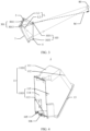
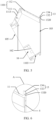
FIG. 1 is a diagram of an application scenario of a transport means according to an implementation of this application; -
FIG. 2a is a sectional view of an optical display according to an implementation of this application; -
FIG. 2b is a three-dimensional exploded view of the optical display shown inFIG. 2a ; -
FIG. 3 is a diagram of a virtual image forming principle of an optical display according to an implementation of this application; -
FIG. 4 is a three-dimensional diagram of a housing of an optical display according to an implementation of this application; -
FIG. 5 is a sectional view of a housing of an optical display according to an implementation of this application; -
FIG. 6 is a locally enlarged diagram of an area A inFIG. 2a ; -
FIG. 7 is a locally enlarged diagram of an area B inFIG. 2a ; -
FIG. 8a is a diagram of a housing of an optical display according to an implementation of this application; -
FIG. 8b is a three-dimensional diagram of a housing of an optical display according to an implementation of this application from another angle of view; -
FIG. 9 is a planar diagram of assembling a housing and a light source unit together according to an implementation of this application; -
FIG. 10a is a diagram of distribution of a fastening post and a positioning post on an installation surface according to an implementation of this application; -
FIG. 10b is a three-dimensional diagram of a housing according to an implementation of this application from still another angle of view; -
FIG. 11 is a three-dimensional exploded view of a housing and a curved mirror according to an implementation of this application; -
FIG. 12 is a planar diagram of a curved mirror according to an implementation of this application; -
FIG. 13 is a diagram of assembling a housing and a curved mirror together according to an implementation of this application; -
FIG. 14 is a locally enlarged diagram of an area C inFIG. 13 ; -
FIG. 15a is a planar diagram of a possible structure of a curved mirror according to an implementation of this application; -
FIG. 15b is a planar diagram of a possible structure of a curved mirror according to an implementation of this application; -
FIG. 15c is a planar diagram of a possible structure of a curved mirror according to an implementation of this application; -
FIG. 15d is a planar diagram of a possible structure of a curved mirror according to an implementation of this application; -
FIG. 16 is a diagram of three-dimensional assembly of a housing and a curved mirror according to an implementation of this application from another angle of view; -
FIG. 17 is another sectional view of an optical display according to an implementation of this application; -
FIG. 18a is a diagram of a partial structure of a transport means according to an implementation of this application; -
FIG. 18b is a diagram of a possible implementation of integrating an optical display into a head-up display; -
FIG. 19 is a diagram of a function of a transport means according to this application; -
FIG. 20 is a diagram of a possible application scenario of an optical display according to an implementation of this application; and -
FIG. 21 is a diagram of another possible application scenario of an optical display according to an implementation of this application. - Refer to
FIG. 1 . An implementation of this application provides a transport means 1000. The transport means 1000 in the implementation of this application may be a known transport means like a vehicle, an aircraft, a boat, or a rocket, or may be a transport means newly emerging in the future. The vehicle may be an electric vehicle, a fuel vehicle, or a hybrid power vehicle, for example, a pure electric vehicle, an extended-range electric vehicle, a hybrid electric vehicle, a fuel cell vehicle, or a new energy vehicle. This is not specifically limited in this application. - The transport means 1000 includes a
cockpit 200 and seats installed in thecockpit 200. The seats include afirst seat 300 and asecond seat 500, and are used for passengers to take. In this implementation, thefirst seat 300 is a front seat disposed in thecockpit 200. Thesecond seat 500 is a rear seat arranged behind thefirst seat 300, and is used for a passenger to take. In another implementation of this application, thefirst seat 300 may not be a front seat. - The
first seat 300 includes aseat body 301 and anoptical display 10 installed on theseat body 301. In this application, a passenger who watches theoptical display 10 on thesecond seat 500 is referred to as a viewer. It may be understood that theoptical display 10 may alternatively be installed at a front-passenger seat (as shown inFIG. 1 ) of the transport means 1000, that is, installed on an instrument panel (Instrument Panel, IP) console of the transport means. - Refer to
FIG. 2a . An implementation of this application provides anoptical display 10, configured to output imaging light that carries image information. - Refer to
FIG. 2a andFIG. 2b . Theoptical display 10 includes ahousing 1, alight source unit 3, a transmissive-reflectiveoptical element 5, acurved mirror 7, aconnection component 8, and acover 9. - The
light source unit 3 is fastened to thehousing 1 and is configured to emit imaging light. The transmissive-reflectiveoptical element 5 is fastened to thehousing 1, and is configured to: transmit and reflect the imaging light. Thecurved mirror 7 is fastened to thehousing 1 by using theconnection component 8, and is configured to reflect the imaging light. Thecover 9 is fastened to thehousing 1, covers thecurved mirror 7, and is configured to: protect thecurved mirror 7 and reduce dust entering thehousing 1. - The imaging light emitted by the
light source unit 3 is reflected to thecurved mirror 7 through the transmissive-reflectiveoptical element 5, and imaging light reflected by thecurved mirror 7 is transmitted to the outside of thehousing 1 through the transmissive-reflectiveoptical element 5. Thelight source unit 3 may be referred to as an image source. The transmissive-reflectiveoptical element 5 may reflect the imaging light emitted by thelight source unit 3 to thecurved mirror 7, and transmit the imaging light reflected by thecurved mirror 7. - In a conventional optical display, optical elements such as a light source and a curved mirror are first fastened to respective fastening frame bodies and then assembled to the housing. In this case, there are a large quantity of elements in the optical display. Since there is an assembly tolerance between elements, a larger quantity of elements may lead to more system/device assembly difficulty and lower assembly accuracy.
- However, in this application, because each of the
light source unit 3, the transmissive-reflectiveoptical element 5, and thecurved mirror 7 is directly fastened to asame housing 1 without using another adapter (for example, a respective fastening frame body), a quantity of elements of theoptical display 10 is reduced, assembly difficulty of theoptical display 10 is reduced, assembly accuracy of theoptical display 10 is improved, and a structure of theoptical display 10 is simplified. This further helps improve accuracy of an optical path system of theoptical display 10, and improve output quality of imaging light of theoptical display 10. - Refer to
FIG. 3 . In some implementations of this application, thecurved mirror 7 may transmit imaging light to the outside of thehousing 1 through the transmissive-reflectiveoptical element 5, and then the imaging light enters aneye 80, so that theeye 80 sees an enlarged virtual image. The virtual image can be viewed by the eye without being received by a light screen. As shown inFIG. 3 , thelight source unit 3 emits imaging light L with a specific divergence angle. The imaging light L enters theeye 80 after being reflected by the transmissive-reflectiveoptical element 5 and thecurved mirror 7. In this case, a brain traces the light backward based on experience of "rectilinear propagation of light", and considers a point at which the imaging light L extended backward intersects as an object point, namely, a virtual image point. A position of theeye 80 may be referred to as an eyebox (Eyebox) position. - In another implementation of this application, the
curved mirror 7 may project the imaging light to a light screen (not shown in the figure) located outside thehousing 1 after the imaging light passes through the transmissive-reflectiveoptical element 5. The light screen may be a wall, a projection screen, a wooden board, or the like. A specific form of the light screen is not limited in this application. - In some implementations of this application, the
housing 1 is an integrally formed housing. In another implementation of this application, thehousing 1 may be formed by assembling two or more parts. - Refer to
FIG. 4 andFIG. 5 . Thehousing 1 includes amain housing 11 and a mountingpart 13. - The
main housing 11 includes a first part 1101 (which may be considered as an upper part of the housing 1) and a second part 1103 (which may be considered as a lower part of the housing 1) that are connected. A cavity enclosed by thefirst part 1101 and thesecond part 1103 includes a mounting opening 103 (as shown inFIG. 5 ) and an assembly opening 105 (both of which may be referred to as two openings, front and rear). The mountingopening 103 communicates with an inner cavity of themain housing 11, and theassembly opening 105 communicates with the inner cavity of themain housing 11. The mountingopening 103 is configured to pass through the imaging light. Theassembly opening 105 is configured to assemble thecurved mirror 7. Thelight source unit 3 is fixedly accommodated in thefirst part 1101. The transmissive-reflectiveoptical element 5 and thecurved mirror 7 are located on thesecond part 1103. - Because the
light source unit 3 is installed and accommodated in thefirst part 1101, and the transmissive-reflectiveoptical element 5 and thecurved mirror 7 are located on thesecond part 1103, it is difficult for a user to see, by using the transmissive-reflectiveoptical element 5, thelight source unit 3 located in thefirst part 1101 when watching theoptical display 10. That is, thelight source unit 3 is hidden in thefirst part 1101. Stray light of thelight source unit 3 does not directly reach a human eye through the transmissive-reflectiveoptical element 5, so that user experience is improved, and imaging quality of theoptical display 10 is also improved. - In some implementations of this application, the
first part 1101 includes afirst side wall 111 and asecond side wall 112 that are in a bent connection. Aninstallation surface 1113 disposed facing the inner cavity of themain housing 11 is disposed on thefirst side wall 111, and is configured to connect to the light source unit 3 (install the light source unit 3). - In some implementations of this application, the
second part 1103 includes athird side wall 113, afourth side wall 114, and afifth side wall 115. Thethird side wall 113 is fixedly connected between thefourth side wall 114 and thefifth side wall 115. - A
positioning groove 106 is formed on an inner wall that is of thethird side wall 113 and that faces the inner cavity of themain housing 11, and is configured to position thecurved mirror 7. - The
fourth side wall 114 and thefifth side wall 115 are arranged oppositely. Thefirst side wall 111 is located between thefourth side wall 114 and thefifth side wall 115. Thesecond side wall 112 is located between thefourth side wall 114 and thefifth side wall 115. Thethird side wall 113 is located between thefourth side wall 114 and thefifth side wall 115. Thefirst side wall 111, thesecond side wall 112, thethird side wall 113, thefourth side wall 114, and thefifth side wall 115 jointly form the inner cavity of themain housing 11. Thesecond side wall 112, thethird side wall 113, thefourth side wall 114, and thefifth side wall 115 jointly form the mountingopening 103. Thefirst side wall 111, thethird side wall 113, thefourth side wall 114, and thefifth side wall 115 jointly form theassembly opening 105. - Refer to
FIG. 6 . The mountingpart 13 protrudes from an outer side surface of themain housing 11, and is configured to fasten the transmissive-reflectiveoptical element 5. An internal optical path of theoptical display 10 is located inside themain housing 11, and the mountingpart 13 for fastening the transmissive-reflectiveoptical element 5 is disposed outside themain housing 11, so that the mountingpart 13 does not affect the internal optical path of theoptical display 10. In other words, the mountingpart 13 does not affect transmission of imaging light inside themain housing 11, thereby reducing generation of reflected stray light of theoptical display 10 and improving output quality of the imaging light of theoptical display 10. - The mounting
part 13 includes a mountingbottom wall 132 and aprotective flange 134. The mountingbottom wall 132 protrudes from an outer side of themain housing 11, and a mountingsurface 1320 is disposed on the mountingbottom wall 132, and is configured to be fixedly connected to the transmissive-reflectiveoptical element 5. In this implementation, the mountingbottom wall 132 protrudes from thesecond side wall 112, thethird side wall 113, thefourth side wall 114, and thefifth side wall 115, and the mountingbottom wall 132 is disposed along a peripheral contour of the mountingopening 103. The mountingsurface 1320 is disposed obliquely relative to the installation surface 1113 (as shown inFIG. 5 ). - The transmissive-reflective
optical element 5 is fixedly connected to the mountingsurface 1320 of the mountingbottom wall 132. The transmissive-reflectiveoptical element 5 is disposed in parallel with the mountingsurface 1320. The mountingsurface 1320 is disposed in parallel with the transmissive-reflectiveoptical element 5, and a position of the mountingsurface 1320 corresponds to a position of the transmissive-reflectiveoptical element 5 in an optical path of theoptical display 10. In a process of assembling the transmissive-reflectiveoptical element 5 and thehousing 1, the mountingsurface 1320 may position the transmissive-reflectiveoptical element 5 in a normal direction of the mountingsurface 1320, so that positioning accuracy of the transmissive-reflectiveoptical element 5 by using thehousing 1 is improved, and output quality of the imaging light in theoptical display 10 is improved. - In some implementations of this application, the transmissive-reflective
optical element 5 is bonded to the mountingbottom wall 132 by using an adhesive. The adhesive may be a double-sided adhesive, or a gluing manner may be adopted. - In another implementation of this application, the transmissive-reflective
optical element 5 and the mountingsurface 1320 may alternatively be disposed in a non-parallel manner. - In another implementation of this application, the mounting
surface 1320 is disposed on an inner wall of thehousing 1, and the transmissive-reflectiveoptical element 5 may alternatively be located inside thehousing 1. - The
protective flange 134 protrudes from the mountingbottom wall 132, and is disposed along a peripheral edge of the mountingbottom wall 132, to protect an edge of the transmissive-reflectiveoptical element 5. In some implementations of this application, theprotective flange 134 is disposed around the transmissive-reflectiveoptical element 5, to enclose the transmissive-reflectiveoptical element 5. In another implementation of this application, theprotective flange 134 protrudes from a part of the peripheral edge of the mountingbottom wall 132, to protect the edge of the transmissive-reflectiveoptical element 5 in segments or areas, that is, theprotective flange 134 protects at least a part of the edge of the transmissive-reflectiveoptical element 5. - The
protective flange 134 encloses at least a part of the edge of the transmissive-reflectiveoptical element 5 to protect the transmissive-reflectiveoptical element 5, reduce a possibility that the transmissive-reflectiveoptical element 5 is scratched and damaged, and further prolong a service life of the transmissive-reflectiveoptical element 5. In addition, theprotective flange 134 encloses at least a part of the edge of the transmissive-reflectiveoptical element 5, so that a possibility that the user is scratched or cut by the edge of the transmissive-reflectiveoptical element 5 can be reduced, and security and reliability of theoptical display 10 can be improved. - In another implementation of this application, the mounting
part 13 may be omitted, and the transmissive-reflectiveoptical element 5 is directly fastened to themain housing 11, or the transmissive-reflectiveoptical element 5 may alternatively be accommodated inside themain housing 11. - Refer to
FIG. 7 . Thehousing 1 further includes afastening post 14 and a lightsource positioning post 15 that protrude from theinstallation surface 1113. Thefastening post 14 is fixedly connected to thelight source unit 3. - The
light source unit 3 may be disposed in parallel with theinstallation surface 1113. A position of theinstallation surface 1113 corresponds to a position of thelight source unit 3 in an optical path of theoptical display 10. In a process of assembling thelight source unit 3 and thehousing 1, theinstallation surface 1113 may position thelight source unit 3 in a normal direction of theinstallation surface 1113, so that positioning accuracy of thelight source unit 3 by using thehousing 1 is improved, and output quality of the imaging light of theoptical display 10 is improved. In another implementation of this application, thelight source unit 3 and theinstallation surface 1113 may alternatively be disposed in a non-parallel manner. - The light
source positioning post 15 is configured to position thelight source unit 3. - Refer to
FIG. 8a andFIG. 8b . Thehousing 1 further includes apositioning part 16 that is disposed on an inner wall of themain housing 11 for positioning thecurved mirror 7. - In some implementations of this application, there are a plurality of
positioning parts 16, and the plurality ofpositioning parts 16 are disposed on the inner wall of themain housing 11. Each of thefirst side wall 111, thefourth side wall 114, and thefifth side wall 115 is provided with thepositioning part 16 facing an inner wall of an inner cavity of themain housing 11. Thepositioning part 16 is approximately in a groove-shaped structure. For example, as shown inFIG. 8b , thepositioning part 16 on thefirst side wall 111 is a groove-shaped structure that is disposed on thefirst side wall 111 and that is located in themain housing 11, and thepositioning part 16 on thefifth side wall 115 is a groove-shaped structure that is recessed in thefifth side wall 115 and that is located in themain housing 11. Eachpositioning part 16 includes afirst positioning surface 162 and aside surface 164. Thefirst positioning surface 162 is disposed facing theassembly opening 105, and is configured to attach to thecurved mirror 7, to improve assembly accuracy between thecurved mirror 7 and thehousing 1. - A structure of the
positioning part 16 is not limited in this application, provided that thepositioning part 16 can position thecurved mirror 7. For example, several protruding posts may protrude from the inner wall of themain housing 11. The several protruding posts enclose onepositioning part 16, and thepositioning part 16 can limit a position of thecurved mirror 7 on thehousing 1. - In some implementations of this application, a normal direction of the
first positioning surface 162 is the same as a normal direction of theassembly opening 105, and first positioning surfaces 162 of the plurality ofpositioning parts 16 may be located on a same plane. In another implementation of this application, the first positioning surfaces 162 of the plurality ofpositioning parts 16 may be parallel to each other or may not be parallel to each other. In another implementation of this application, the normal direction of thefirst positioning surface 162 may be different from the normal direction of theassembly opening 105. - The
housing 1 further includes apositioning post 18 that protrudes from thefirst positioning surface 162, and that is configured to position thecurved mirror 7. - The
housing 1 further includes aconnection post 19 that protrudes from thefirst positioning surface 162, and that is configured to be fixedly connected to thecurved mirror 7. - In another implementation of this application, the
housing 1 may not be an integrally formed housing. - In another implementation of this application, a structure of the
housing 1 is not limited. For example, the mountingopening 103 and theassembly opening 105 are located on thesecond part 1103, and thehousing 1 can fasten thelight source unit 3, the transmissive-reflectiveoptical element 5, and thecurved mirror 7, so that theoptical display 10 can output imaging light. - In another implementation of this application, the
assembly opening 105 may be omitted, and thecurved mirror 7 is fixedly accommodated in thehousing 1. - According to the
optical display 10 provided in this application, because thelight source unit 3, the transmissive-reflectiveoptical element 5, and thecurved mirror 7 are integrated on thehousing 1 as a whole, relative positions of thelight source unit 3, the transmissive-reflectiveoptical element 5, and thecurved mirror 7 are determined based on an optical principle. This ensures display effect of theoptical display 10. - In some implementations of this application, the
light source unit 3 uses a liquid crystal display (liquid crystal display, LCD) imaging technology. LCD imaging uses a principle of photoelectric effect of liquid crystals. An arrangement state of liquid crystal molecules changes due to impact of an external electric field. Liquid crystal molecules in different arrangement states can control a light transmittance. For example, there are liquid crystal molecules between two polarizers whose polarization directions are perpendicular to each other. When no electric field is applied, the liquid crystal molecules can rotate a polarization direction of linearly polarized light passing through a first polarizer by 90°. In this case, the light passes through a second polarizer at a maximum transmittance. When an electric field is applied, an arrangement state of the liquid crystal molecules changes, a rotation angle of polarized light also changes, and intensity of the light passing through the second polarizer decreases. Each pixel of an LCD includes three primary colors. A color picture is displayed by controlling strength of the three primary colors. A type of a light source of thelight source unit 3 is not limited in this application. For example, thelight source unit 3 may further use a digital light processing (digital light processing, DLP) technology, laser scanning projection, or the like. - In some implementations of this application, refer to
FIG. 9 . Thelight source unit 3 includes a light-emittingarea 301 and anon-light emitting area 302. The light-emittingarea 301 is configured to emit imaging light. Thenon-light emitting area 302 may be a frame of thelight source unit 3. In some implementations of this application, thenon-light emitting area 302 is fixedly connected to thefastening post 14. - The
non-light emitting area 302 is disposed around the light-emittingarea 301, and is provided with afastening hole 31. A quantity of fastening holes 31 corresponds to a quantity of fastening posts 14. There are fourfastening holes 31, and the fourfastening holes 31 are distributed at four corners of thelight source unit 3. Refer toFIG. 10a . There are four fastening posts 14. Thefastening post 14 is a stud, and is provided with a threaded hole fitting a screw. After penetrating through thefastening hole 31, the screw is fastened in and penetrates through the threaded hole of thefastening post 14, so that thelight source unit 3 is fastened to thefastening post 14. A shape of thelight source unit 3 is not limited in this application. For example, thelight source unit 3 may be in a circular shape or an irregular shape, and thelight source unit 3 may emit imaging light. In another implementation of this application, thefastening post 14 may be fastened in and penetrate through thefastening hole 31. - A
positioning hole 33 is provided on thenon-light emitting area 302, and is configured to dispose the lightsource positioning post 15 in a penetrating manner, so as to position thelight source unit 3 on thehousing 1. - In some implementations of this application, the
positioning hole 33 includes afirst positioning hole 332 and asecond positioning hole 334. The lightsource positioning post 15 includes a first lightsource positioning post 152 and a second lightsource positioning post 154. The first lightsource positioning post 152 penetrates through thefirst positioning hole 332, and the second lightsource positioning post 154 penetrates through thesecond positioning hole 334. In an arrangement direction of thefirst positioning hole 332 and thesecond positioning hole 334, a length of thefirst positioning hole 332 is greater than a length of thesecond positioning hole 334. For example, thesecond positioning hole 334 is a circular hole, and thefirst positioning hole 332 is a long-strip-shaped hole whose length in the first direction is greater than a diameter of thesecond positioning hole 334. - In an ideal state, a shape of the
positioning hole 33 adapts to a shape of the lightsource positioning post 15, and a preset spacing (a designed spacing) between twopositioning holes 33 is the same as a preset spacing between two light source positioning posts 15. For example, thepositioning hole 33 is circular, and the lightsource positioning post 15 is cylindrical. However, in practice, a manufacturing error inevitably exists, so that an error exists between an actual spacing between two light source positioning posts 15 and the preset spacing. In this case, the lightsource positioning post 15 of thelight source unit 3 may fail to be installed into thecorresponding positioning hole 33. - In this application, in the arrangement direction of the
first positioning hole 332 and thesecond positioning hole 334, the length of thefirst positioning hole 332 is greater than the length of thesecond positioning hole 334, and an assembly margin is reserved when thelight source unit 3 is assembled on thehousing 1 through thefirst positioning hole 332. In other words, when a difference exists between an actual spacing between the first lightsource positioning post 152 and the second lightsource positioning post 154 and the preset spacing, thelight source unit 3 may also be assembled on thehousing 1. For example, when the actual spacing between the first lightsource positioning post 152 and the second lightsource positioning post 154 is greater than the preset spacing, the first lightsource positioning post 152 can still be installed into thefirst positioning hole 332, and the second lightsource positioning post 154 can still be installed into thesecond positioning hole 334. In this way, requirements on manufacturing accuracy of thehousing 1 and theoptical display 10 and manufacturing costs are reduced. - In another implementation of this application, the
fastening post 14, the first lightsource positioning post 152, and the second lightsource positioning post 154 may be all omitted. Thelight source unit 3 may be directly fastened to theinstallation surface 1113 of thefirst side wall 111. How to fasten thelight source unit 3 and thehousing 1 is not limited in this application. For example, thelight source unit 3 may omit thenon-light emitting area 302, the light-emittingarea 301 of thelight source unit 3 is pasted on thefirst side wall 111 by using an adhesive, and thelight source unit 3 covers thefirst side wall 111. - In another implementation of this application, the
light source unit 3 may alternatively be fastened outside thehousing 1, that is, theinstallation surface 1113 may be disposed on an outer side surface of thehousing 1. For example, a light transmission area may be disposed on a side wall of thehousing 1, and imaging light emitted by thelight source unit 3 enters an inner cavity of thehousing 1 through the light transmission area. The light transmission area may be a through hole, or may be a transparent area. - Refer to
FIG. 9 andFIG. 3 . The light-emittingarea 301 includes a first light-emittingarea edge 3011 and a second light-emittingarea edge 3013 that are arranged oppositely. In some implementations of this application, the first light-emittingarea edge 3011 is disposed at an end that is of the light-emittingarea 301 and that is close to the mountingopening 103. The second light-emittingarea edge 3013 is disposed at an end that is of the light-emittingarea 301 and that is away from the mountingopening 103. Imaging light L includes imaging light L1 and imaging light L2. The two channels of imaging light limit a divergence angle of light emitted by thelight source unit 3. The imaging light L1 is emitted from the first light-emittingarea edge 3011, and the imaging light L2 is emitted from the second light-emittingarea edge 3013. - The light-emitting
area 301 of thelight source unit 3 has a light-emitting surface, and the transmissive-reflectiveoptical element 5 has a reflective surface. The light-emitting surface of thelight source unit 3 is disposed obliquely relative to the reflective surface of the transmissive-reflectiveoptical element 5, and no other optical element is required. Imaging light emitted from the light-emitting surface may be directly incident to the transmissive-reflectiveoptical element 5, so that an internal optical path of theoptical display 10 and a structure of theoptical display 10 are simplified. - Refer to
FIG. 3 andFIG. 10b . The mountingopening 103 includes afirst mounting edge 1031 and asecond mounting edge 1033 that are arranged oppositely. Thefirst mounting edge 1031 is located at an edge of an end that is of thesecond side wall 112 and that is away from theassembly opening 105. Thesecond mounting edge 1033 is located at an edge of an end that is of thethird side wall 113 and that is away from theassembly opening 105. A first point on thefirst mounting edge 1031 and a second point on theedge 3013 of the second light-emitting area are located on a connection line M. The first light-emittingarea edge 3011 is located on a first side of the connection line M, and thesecond mounting edge 1033 is located on a second side of the connection line M. When a user uses theoptical display 10, theeye 80 is located on a first side on which thefirst mounting edge 1031 is located, and theeye 80 is located above the connection line M, so that theeye 80 does not directly see the light-emitting area 301 (namely, a bright spot) of thelight source unit 3 during normal viewing. This prevents stray light of thelight source unit 3 from being directly transmitted to human eyes through the transmissive-reflective optical element 5 (in a normal case, the stray light is first reflected by the transmissive-reflectiveoptical element 5 to thecurved mirror 7, then is reflected by thecurved mirror 7, and then is incident to the human eyes through the transmissive-reflective optical element 5), so that display effect of theoptical display 10 is improved and user experience is also improved. - It can be learned from
FIG. 3 that thefirst mounting edge 1031 included in the mountingopening 103 may be referred to as an upper edge of the mountingopening 103, and thesecond mounting edge 1033 may be referred to as a lower edge of the mountingopening 103. Correspondingly, the first light-emittingarea edge 3011 of the light-emittingarea 301 may be referred to as an upper edge of the light-emittingarea 301, and the second light-emittingarea edge 3013 may be referred to as a lower edge of the light-emittingarea 301. - The transmissive-reflective
optical element 5 is an optical element that can transmit a part of incident light that is incident to the transmissive-reflectiveoptical element 5 and reflect a part of the incident light. For example, the transmissive-reflective optical element can transmit 50% of incident light, and the transmissive-reflective optical element can reflect 50% of the incident light. Alternatively, the transmissive-reflective optical element can transmit 30% of incident light, and the transmissive-reflective optical element can reflect 70% of the incident light. A proportion of the incident light transmitted by the transmissive-reflectiveoptical element 5 to the total incident light may be selected based on a requirement. The transmissive-reflectiveoptical element 5 may be made of glass, or the like. - In this implementation, the
curved mirror 7 is a reflector that matches a free-form surface required for optical imaging. - A surface of an optical element used in conventional optical design is a standard spherical surface. Usually, a plurality of spherical mirrors need to cooperate to correct an aberration. Consequently, an optical structure of the optical element is complex, and large space is occupied.
- As the optical industry develops, design and manufacturing technologies of complex aspheric surfaces are greatly improved. Aspheric surfaces are usually quadratic surfaces such as a parabolic surface, an ellipsoidal surface, an involute surface, and a hyperbolic surface with a rotating axis, high-order surfaces, and non-rotating aspheric surfaces such as an off-axis aspheric surface. In different use scenarios, one aspheric surface may usually replace two or more spherical surfaces to correct an aberration, to simplify the optical structure and implement miniaturization and lightweight of an optical path.
- Compared with the aspheric surface, a free-form surface is a more complex optical structure. A curvature radius of each point on the surface is different, and a degree of freedom of the surface is very high. The free-form surface can not only replace a plurality of aspheric surfaces to correct an aberration, but also maximally improve optical quality and simplify the optical structure. An optical free-form surface has a complex structure, a high degree of freedom, and no clear expression definition. Generally, an optical surface that does not have global rotational symmetry, does not have a unified optical axis, and has a plurality of curvature radii on the entire surface is considered as an optical free-form surface.
- In another implementation of this application, the
curved mirror 7 may alternatively be a spherical reflector or an aspheric reflector. This is not limited in this application. - Refer to
FIG. 11 andFIG. 12 . Thecurved mirror 7 includes amirror body 72, aconnection part 74, and apositioning protrusion 76. Theconnection part 74 protrudes from themirror body 72, and theconnection part 74 is accommodated in thepositioning part 16, and is configured to be combined and fixedly connected with thepositioning part 16. Thepositioning protrusion 76 protrudes from themirror body 72, and thepositioning protrusion 76 is accommodated in thepositioning groove 106. - The
mirror body 72 includes afirst edge 722, asecond edge 724, athird edge 726, and afourth edge 728. Thefirst edge 722 and thesecond edge 724 are arranged oppositely in a first direction (for example, an X direction shown inFIG. 11 andFIG. 12 ). Thethird edge 726 and thefourth edge 728 are arranged oppositely in a second direction (for example, a Y direction shown inFIG. 11 andFIG. 12 ), and the first direction is different from the second direction. A normal direction of thefirst positioning surface 162 is a third direction (a Z direction shown inFIG. 11 andFIG. 12 ), the third direction is different from the first direction, and the third direction is different from the second direction. In this implementation, the first direction is perpendicular to the second direction, the first direction is perpendicular to the third direction, and the second direction is perpendicular to the third direction. Thefirst edge 722 is disposed on a side on which themirror body 72 is adjacent to thefourth side wall 114. Thesecond edge 724 is disposed on a side on which themirror body 72 is adjacent to thefifth side wall 115. Thethird edge 726 is disposed on a side on which themirror body 72 is adjacent to thefirst side wall 111. Thefourth edge 728 is disposed on a side on which themirror body 72 is adjacent to thethird side wall 113. In some implementations of this application, in the second direction, in a direction from thefourth edge 728 of thecurved mirror 7 to thethird edge 726, a position of the light-emittingarea 301 of thelight source unit 3 is higher than a position of thecurved mirror 7 and a position of the transmissive-reflective optical element 5 (as shown inFIG. 1 andFIG. 3 ). - In some implementations of this application, there are a plurality of
connection parts 74. Eachconnection part 74 is correspondingly accommodated in onepositioning part 16, and is fixedly connected to thefirst positioning surface 162 in thepositioning part 16. -
Connection parts 74 protrude from thefirst edge 722, thesecond edge 724, and thethird edge 726. Eachconnection part 74 is correspondingly accommodated in onepositioning part 16. Eachconnection part 74 is fixedly connected to thefirst positioning surface 162 in thepositioning part 16 by using theconnection component 8. In this implementation, oneconnection part 74 protrudes from each of thefirst edge 722 and thesecond edge 724, and twoconnection parts 74 protrude from thethird edge 726. The fourconnection parts 74 are approximately located at four corners of themirror body 72. - The
connection part 74 on thefirst edge 722, theconnection part 74 on thesecond edge 724, and theconnection part 74 on thethird edge 726 cooperate with thecorresponding positioning parts 16, so that thecurved mirror 7 can be positioned on themain housing 11. - Each
connection part 74 is further provided with agroove 742 that penetrates through theconnection part 74 in the third direction, and the groove is configured to dispose thepositioning post 18 in a penetrating manner. Refer toFIG. 13 andFIG. 14 . Each positioning post 18 on thehousing 1 penetrates through thegroove 742 of oneconnection part 74, and is configured to position theconnection part 74. This facilitates assembly between thecurved mirror 7 and thehousing 1, and improves assembly accuracy and assembly efficiency of theoptical display 10. - A second positioning surface 740 (as shown in
FIG. 12 ) that presses against or is attached to thefirst positioning surface 162 is disposed on a side that is of eachconnection part 74 and that faces thefirst positioning surface 162. A reflection layer (for example, a reflection coating) is disposed on thecurved mirror 7 to form a reflection surface for reflecting imaging light. The reflection surface may be located on a side that is of thecurved mirror 7 and that faces theassembly opening 105, or the reflection surface may be located on a side that is of thecurved mirror 7 and that is away from theassembly opening 105, namely, a side that faces the mountingopening 103. The second positioning surface 740 may be provided with a reflection layer, or may not be provided with a reflection layer. Thefirst positioning surface 162 and the second positioning surface 740 are parallel to and press against each other, to implement positioning of thecurved mirror 7 in the third direction and limit thecurved mirror 7 to rotate around the first direction and the second direction. In some implementations of this application, second positioning surfaces 740 of the plurality ofconnection parts 74 are located on a same plane. In another implementation of this application, thefirst positioning surface 162 and the second positioning surface 740 may be disposed in a non-parallel manner, and the second positioning surfaces 740 of the plurality ofconnection parts 74 may be disposed in parallel or in a non-parallel manner. - Through cooperation between the
connection part 74 disposed on the edge of themirror body 72 and thecorresponding positioning part 16, thecurved mirror 7 is positioned in three directions, and rotation of thecurved mirror 7 around the three directions is also limited. This helps further improve position stability of thecurved mirror 7 relative to thehousing 1, and further improves display quality of theoptical display 10. - Due to a difference in manufacturing materials, a thermal expansion coefficient of the curved mirror and a thermal expansion coefficient of another fitting component (for example, a housing) of the optical display are usually different. Therefore, when an ambient temperature changes greatly, the curved mirror is easily deformed due to squeezing of the another fitting component. The curved mirror and the housing are used as an example. When the ambient temperature of the optical display is greater than a preset temperature (for example, 70 degrees Celsius), the curved mirror and the housing are deformed due to thermal expansion, and the housing may squeeze the curved mirror. Once the curved mirror is deformed, an optical path of imaging light reflected by a deformed part is distorted, and consequently, output quality of the imaging light of the optical display is affected.
- In some implementations of this application, a thermal expansion coefficient of the
curved mirror 7 is different from a thermal expansion coefficient of thehousing 1. Due to a thermal expansion factor of thehousing 1 and thecurved mirror 7, a reserved gap 700 (as shown inFIG. 14 ) exists between edges (including thefirst edge 722, thesecond edge 724, thethird edge 726, thefourth edge 728, and the edges of the connection parts 74) of thecurved mirror 7, to reserve thermal expansion space for thecurved mirror 7 and thehousing 1. This reduces a possibility that thecurved mirror 7 is deformed due to squeezing, and improves optical path stability of theoptical display 10. - The
reserved gap 700 includes a firstreserved gap 701 and a secondreserved gap 702. The firstreserved gap 701 is provided between theside surface 164 and an edge of theconnection part 74, to reserve thermal expansion space for theconnection part 74 and thehousing 1. - The second
reserved gap 702 is provided between an inner wall of thegroove 742 of eachconnection part 74 and thecorresponding positioning post 18, to reserve thermal expansion space between the positioningpost 18 and theconnection part 74. In some implementations of this application, a length of themirror body 72 in the first direction is greater than a length of themirror body 72 in the second direction, and a thermal expansion degree of thecurved mirror 7 in the first direction may be greater than a thermal expansion degree of thecurved mirror 7 in the second direction. Thepositioning part 16 on thefourth side wall 114 and thecorresponding connection part 74 are used as an example. In the first direction, the secondreserved gap 702 exists between a part of the inner wall of thegroove 742 and thecorresponding positioning post 18. In the second direction, a part of the inner wall of thegroove 742 is closely attached to thecorresponding positioning post 18, to reduce a possibility of deformation of thecurved mirror 7 caused by thermal expansion and improve positioning accuracy of thepositioning part 16 on theconnection part 74. In another implementation of this application, the length of themirror body 72 in the first direction is greater than or equal to the length of themirror body 72 in the second direction. - With reference to
FIG. 12 , thepositioning protrusion 76 protrudes from thefourth edge 728 of themirror body 72, and thepositioning protrusion 76 is accommodated in thepositioning groove 106 and is fastened to an inner wall of thepositioning groove 106 for positioning thecurved mirror 7 in the first direction. This can improve assembly efficiency and assembly accuracy when thecurved mirror 7 is assembled on thehousing 1. A shape of thepositioning protrusion 76 may be a square, a cone, or the like. A shape of thepositioning protrusion 76 is not limited in this application. In another implementation of this application, thepositioning protrusion 76 may be accommodated in thepositioning groove 106. - A quantity and positions of
connection parts 74 on thecurved mirror 7 are not limited in this application, and a quantity and positions of positioningprotrusions 76 on the edge of themirror body 72 are not limited in this application. For example, as shown inFIG. 15a , in a possible implementation, theconnection part 74 on thethird edge 726 may be omitted, theconnection part 74 on thefirst edge 722 is disposed close to thethird edge 726, theconnection part 74 on thesecond edge 724 is disposed close to thethird edge 726, and twoconnection parts 74 may protrude from thefourth edge 728. As shown inFIG. 15b , in a possible implementation, thepositioning protrusion 76 on thefourth edge 728 may be omitted, and noconnection part 74 is disposed on thefourth edge 728. As shown inFIG. 15c , in a possible implementation, theconnection part 74 on thefirst edge 722 may be omitted, and theconnection part 74 on thesecond edge 724 may be omitted. Thepositioning protrusion 76 is disposed on each of thethird edge 726 and thefourth edge 728. Thecurved mirror 7 is fastened to the housing by fastening thepositioning protrusion 76 to thepositioning groove 106. As shown inFIG. 15d , in a possible implementation, thepositioning protrusion 76 is disposed on each of thefirst edge 722, thesecond edge 724, thethird edge 726, and thefourth edge 728. - In another implementation of this application, the
positioning post 18, thepositioning part 16, and theconnection post 19 may be omitted, and theconnection part 74 is directly fastened to thehousing 1 by using an adhesive or in another manner. - A shape of the
mirror body 72 is not limited in this application, a quantity of edges of themirror body 72 is not limited, and a quantity ofconnection parts 74 is not limited. For example, in another implementation of this application, themirror body 72 may be circular, there may be one edge of themirror body 72, there may be oneconnection part 74, and theconnection part 74 protrudes from themirror body 72. - In this application, the
positioning protrusion 76 is not limited to being disposed on thefourth edge 728, and thepositioning protrusion 76 is disposed on an edge of themirror body 72. In another implementation of this application, thepositioning groove 106 and thepositioning protrusion 76 may be omitted. - In another implementation of this application, the
curved mirror 7 may not be accommodated in the inner cavity of themain housing 11, thecurved mirror 7 fixedly covers theassembly opening 105, thepositioning part 16 may be disposed on an outer side of thehousing 1, thefirst positioning surface 162 may be located on an outer side of thehousing 1, and thepositioning groove 106 may also be provided on an outer side of thehousing 1. - Refer to
FIG. 2b ,FIG. 11 ,FIG. 16, and FIG. 17 . There are a plurality ofconnection components 8. Eachconnection component 8 includes aflexible buffer 82, apressing sheet 84, afirst fastening member 86, and asecond fastening member 88. Theflexible buffer 82 is fastened between theconnection part 74 and thepressing sheet 84, and theconnection part 74, theflexible buffer 82, and thepressing sheet 84 are sequentially stacked. Thefirst fastening member 86 penetrates through thepressing sheet 84 and the groove 742 (as shown inFIG. 14 ) of theconnection part 74 and is fixedly connected to onepositioning post 18. Thesecond fastening member 88 penetrates through thepressing sheet 84 and is fixedly connected to oneconnection post 19. Both thefirst fastening member 86 and thesecond fastening member 88 apply a force to thepressing sheet 84, and thepressing sheet 84 presses theconnection part 74 on thefirst positioning surface 162, to implement a fixed connection between thehousing 1 and thecurved mirror 7. Theflexible buffer 82 may alternatively be located between thefirst fastening member 86 and thesecond fastening member 88. In another implementation of this application, thefirst fastening member 86 and thesecond fastening member 88 may penetrate through theflexible buffer 82, and a length of theflexible buffer 82 and a length of thepressing sheet 84 may be less than or equal to a length of thepressing sheet 84. - The
flexible buffer 82 has an elastic deformation capability. Theflexible buffer 82 can reduce a possibility that theconnection part 74 is damaged because thepressing sheet 84 is pressed tightly. In addition, theflexible buffer 82 can absorb vibration, improve an anti-seismic capability of theoptical display 10, and further improve quality of the imaging light output by theoptical display 10. Theflexible buffer 82 may be made of a rubber strip, foam, silicon rubber, or another elastomer material. In some implementations of this application, hardness of thepressing sheet 84 is greater than hardness of theflexible buffer 82. Thepressing sheet 84 may be selected but is not limited to one of a sheet metal part, a die casting part, or a plastic part. - The
curved mirror 7 is pressed onto thehousing 1 by using thepressing sheet 84, and a position of thecurved mirror 7 is limited between thehousing 1 and thepressing sheet 84. This improves position stability of thecurved mirror 7 on thehousing 1, reduces a possibility that thecurved mirror 7 is damaged due to a large local force, and prolongs a service life of thecurved mirror 7, thereby helping improve use reliability of theoptical display 10. - In some implementations of this application, the
first fastening member 86 and thesecond fastening member 88 are screws. Both thepositioning post 18 and theconnection post 19 are provided with threaded holes. Thefirst fastening member 86 is in a threaded connection to thepositioning post 18, and thesecond fastening member 88 is in a threaded connection to theconnection post 19. Theconnection post 19 may be, but is not limited to, one of a self-tapping stud, a hot-melt nut, or an in-mold decorative nut. Both thefirst fastening member 86 and thesecond fastening member 88 penetrate through thepressing sheet 84 and are fixedly connected to thehousing 1, to press and fasten thecurved mirror 7 to thehousing 1. This improves connection strength and connection stability between thecurved mirror 7 and thehousing 1. - In some implementations of this application, the
connection part 74 and thepositioning protrusion 76 may be omitted, and thecurved mirror 7 is directly fastened to thehousing 1 by using theconnection component 8. - In some implementations of this application, the
positioning part 16, thefirst positioning surface 162, thepositioning post 18, and theconnection post 19 may be omitted from thehousing 1. Thesecond fastening member 88 and thepressing sheet 84 may be omitted from theconnection component 8, and theflexible buffer 82 and thecurved mirror 7 are directly fastened to thehousing 1 by using thefirst fastening member 86. For example, thefirst fastening member 86 may be fixedly connected to thehousing 1 through theflexible buffer 82. - In some other implementations of this application, the transport means may be a truck, a motorcycle, a bus, a boat, a helicopter, a lawn mower, a recreational vehicle, a playground vehicle, construction equipment, a tram, a golf cart, a train, a trolley, or the like. This is not specifically limited in this application.
- As shown in
FIG. 18a , in a possible implementation, theoptical display 10 in this application is integrated into an in-vehicle display. The in-vehicle display may be installed on the back of a seat of the transport means 1000, or the in-vehicle display may be installed at another position like a front-passenger seat. A position at which the in-vehicle display is installed is not limited in this application. - As shown in
FIG. 18b , theoptical display 10 is integrated into a head-up display (Head-up display, HUD) inFIG. 18b . The HUD can project navigation information, instrument information, and the like to a front field of view angle of a driver to prevent the driver from looking down to view the information, which affects driving safety. The transport means further include areflective part 201, configured to project imaging light emitted by the HUD to the outside of the transport means. Thereflective part 201 may be windshield. After the imaging light emitted by the HUD is reflected by thereflective part 201, a virtual image is formed outside the transport means. A type of the HUD includes but is not limited to a windshield (Windshield, W)-HUD, an augmented reality head-up display (AR-HUD), and the like. InFIG. 18a , theoptical display 10 partially protrudes from the back of the seat. The optical display may alternatively be completely embedded into the back of the seat, that is, the optical display does not protrude from the back of the seat. - In still another possible implementation, the
optical display 10 in this application may alternatively be integrated into a vehicle light. In addition to a lighting function, the vehicle light can also implement an adaptive driving beam (Adaptive Driving Beam, ADB), which can project complex images such as a text or a traffic sign, and project a picture like a video to add a driving assistance or entertainment function. -
FIG. 19 is a functional diagram of a transport means according to an embodiment of this application. - The transport means may include various subsystems such as a
sensor system 21, acontrol system 22, one or more peripheral devices 23 (one peripheral device is used as an example in the figure), apower supply 24, acomputer system 25, and adisplay system 26. The foregoing subsystems may communicate with each other. Thedisplay system 26 may include the display apparatus provided in embodiments of this application. The transport means may further include another functional system, for example, an engine system or a cockpit that provides power for the transport means. This is not limited herein in this application. - The
sensor system 21 may include several detection apparatuses. The detection apparatuses can sense measured information, and convert the sensed information into an electrical signal or other information in a required form based on a specific rule for output. As shown inFIG. 19 , the detection apparatuses may include a global positioning system (global positioning system, GPS), a vehicle speed sensor, an inertial measurement unit (inertial measurement unit, IMU), a radar unit, a laser rangefinder, a camera apparatus, a wheel speed sensor, a steering sensor, a gear sensor, another element used for automatic detection, or the like. This is not limited in this application. - The
control system 22 may include several elements, for example, a steering unit, a brake unit, a lighting system, an autonomous driving system, a map navigation system, a network time system, and an obstacle avoidance system shown in the figure. Thecontrol system 22 may receive information (such as a vehicle speed and a vehicle distance) sent by thesensor system 21, to implement functions such as autonomous driving and map navigation. - Optionally, the
control system 22 may further include elements such as a throttle controller and an engine controller that are configured to control a driving speed of a vehicle, and the like, and this is not limited in this application. - The
peripheral device 23 may include several elements such as a communication system, a touchscreen, a user interface, a microphone, and a speaker. The communication system is configured to implement network communication between the transport means and another device other than the transport means. In actual application, the communication system may use a wireless communication technology or a wired communication technology to implement network communication between the transport means and the another device. The wired communication technology may mean that a vehicle communicates with the another device through a network cable, an optical fiber, or the like. - The
power supply 24 represents a system for providing power or energy for the vehicle, and may include but is not limited to a rechargeable lithium battery and lead-acid battery. In actual application, one or more battery modules in the power supply are configured to provide electrical energy or energy for starting the vehicle. A type and a material of the power supply are not limited in this application. - Several functions of the transport means may be controlled and implemented by the
computer system 25. Thecomputer system 25 may include one or more processors 2501 (one processor is shown as an example in the figure) and a memory 2502 (that may also be referred to as a storage apparatus). In actual application, thememory 2502 is inside thecomputer system 25, or may be outside thecomputer system 25, for example, may be used as a cache in the transport means. This is not limited in this application. - The
processor 2501 may include one or more general-purpose processors such as a graphics processing unit (graphics processing unit, GPU). Theprocessor 2501 may be configured to run a related program stored in thememory 2502 or instructions corresponding to a program, to implement a corresponding function of the vehicle. - The
memory 2502 may include a volatile memory (volatile memory), for example, a RAM. The memory may alternatively include a non-volatile memory (non-volatile memory), for example, a ROM, a flash memory (flash memory), an HDD, or a solid-state drive SSD. Thememory 2502 may alternatively include a combination of the foregoing types of memories. Thememory 2502 may be configured to store a set of program code or instructions corresponding to program code, so that theprocessor 2501 invokes the program code or the instructions stored in thememory 2502 to implement a corresponding function of the vehicle. In this application, thememory 2502 may store a set of program code for controlling the vehicle. Theprocessor 2501 may control safe driving of the vehicle by invoking the program code. How to implement safe driving of the vehicle is specifically described in detail below in this application. - Optionally, in addition to storing the program code or the instructions, the
memory 2502 may further store information such as a road map, a driving route, sensor data, and the like. Thecomputer system 25 may implement a vehicle-related function in combination with other elements in the diagram of the functional framework of the vehicle, for example, a sensor and a GPS in the sensor system. For example, thecomputer system 25 may control a driving direction, a driving speed, or the like of the transport means based on data input of thesensor system 21, and this is not limited in this application. - The
display system 26 may interact with another system in the transport means. For example, thedisplay system 26 may display navigation information sent by thecontrol system 22, or play a video sent by thecomputer system 25 and theperipheral device 23. For a specific structure of thedisplay system 26, refer to the foregoing embodiment of the display apparatus. Details are not described herein again. - The four subsystems shown in this embodiment, namely, the
sensor system 21, thecontrol system 22, thecomputer system 25, and thedisplay system 26, are merely examples, and do not constitute a limitation. In actual application, the transport means may combine several elements in the vehicle based on different functions, to obtain subsystems with corresponding different functions. In actual application, the transport means may include more or fewer systems or elements. This is not limited in this application. - The transport means in embodiments of this application may be a known transport means like a vehicle, an aircraft, a boat or a rocket, or may be a transport means newly emerging in the future. The vehicle may be an electric vehicle, a fuel vehicle, or a hybrid power vehicle, for example, a pure electric vehicle, an extended-range electric vehicle, a hybrid electric vehicle, a fuel cell vehicle, or a new energy vehicle. This is not specifically limited in this application.
- The
optical display 10 is not limited to being used for the transport means 1000 in this application, and theoptical display 10 may also be used for another device. In a possible application scenario, the optical display in this application is integrated into a near eye display (Near Eye Display, NED) device, and a NED device, for example, may be an AR device or a VR device. The AR device may include but is not limited to AR glasses or an AR helmet, and the VR device may include but is not limited to VR glasses or a VR helmet. Refer toFIG. 20 . AR glasses are used as an example. A user may wear an AR glasses device to play a game, watch a video, participate in a virtual conference, perform video shopping, or the like. - In another possible application scenario, the
optical display 10 in this application is integrated into a projector. Refer toFIG. 21 . The projector may project an image onto a wall or a projection screen. - The foregoing application scenario is merely an example. The optical display provided in this application may be further applied to another possible scenario, for example, a medical device. This is not limited in this application.
- Orientation terms mentioned in this application, for example, "on", "below", "front", "back", "left", "right", "inside", "outside", and "side wall", are merely directions based on the accompanying drawings. Therefore, the orientation terms are used to better and more clearly describe and understand this application, instead of indicating or implying that a specified apparatus or element needs to have a specific orientation, and be constructed and operated in the specific orientation. Therefore, this cannot be understood as a limitation on this application.
- In addition, in this specification, the sequence numbers, such as "first" and "second", of components are merely intended to distinguish between the described objects, and do not have any sequential or technical meaning. Unless otherwise specified, the "connection" in this application includes a direct connection and an indirect connection.
- The foregoing description is merely a specific implementation of this application, but is not intended to limit the protection scope of this application. Any variation or replacement readily figured out by a person skilled in the art within the technical scope disclosed in this application shall fall within the protection scope of this application. Therefore, the protection scope of this application shall be subject to the protection scope of the claims.
Claims (13)
- An optical display, comprising:a housing that is provided with a first positioning surface;a light source unit that is fastened to the housing and is configured to emit imaging light; anda curved mirror, comprising a mirror body and a connection part protruding from the mirror body, wherein the mirror body is configured to reflect the imaging light to the outside of the housing, and the connection part is fixedly connected to the first positioning surface.
- The optical display according to claim 1, wherein
the connection part is provided with a groove, the housing further comprises a positioning post protruding from the first positioning surface, and the positioning post penetrates through the groove. - The optical display according to claim 2, wherein
a reserved gap exists between an inner wall of the groove and the positioning post. - The optical display according to claim 2, wherein
the housing further comprises a positioning part disposed on the housing, the first positioning surface is disposed on an inner wall of the positioning part, and the connection part is accommodated in the positioning part. - The optical display according to claim 4, wherein
the inner wall of the positioning part further comprises a side surface connected to the first positioning surface, and a reserved gap exists between the side surface and an edge of the connection part. - The optical display according to claim 2, wherein
there are a plurality of connection parts, the mirror body comprises a first edge, a second edge, a third edge, and a fourth edge, the first edge and the second edge are arranged oppositely in a first direction, the third edge and the fourth edge are arranged oppositely in a second direction, the first direction is different from the second direction, each of the first edge, the second edge, and the third edge is provided with the connection part, the groove provided for the connection part penetrates through the connection part in a third direction, the third direction is different from the first direction, and the third direction is different from the second direction. - The optical display according to claim 2, wherein
the optical display further comprises a connection component, the connection component comprises a pressing sheet and a first fastening member, the curved mirror is located between the pressing sheet and the housing, the first fastening member penetrates through the pressing sheet and the positioning post, and the pressing sheet presses the curved mirror onto the housing. - The optical display according to claim 7, wherein
the housing further comprises a connection post protruding from the first positioning surface, the connection component further comprises a second fastening member, and the second fastening member is fixedly connected to the connection post. - The optical display according to claim 7, wherein
the connection component further comprises a flexible buffer, and the flexible buffer is located between the pressing sheet and the connection part. - The optical display according to claim 1, wherein
the housing is provided with a positioning slot, the curved mirror comprises a mirror body and a positioning protrusion protruding from an edge of the mirror body, and the positioning protrusion is accommodated in the positioning slot. - The optical display according to any one of claims 1 to 10, whereinthe housing is provided with an assembly opening that communicates with an inner cavity of the housing, and the curved mirror is disposed in the assembly opening; andthe optical display further comprises a cover, and the cover is fixedly connected to the housing and covers the curved mirror.
- A seat, comprising the optical display according to any one of claims 1 to 11, wherein the optical display is installed on the seat.
- A transport means, comprising the optical display according to any one of claims 1 to 11, wherein the optical display is installed on the transport means.
Applications Claiming Priority (2)
| Application Number | Priority Date | Filing Date | Title |
|---|---|---|---|
| CN202210469112.6A CN117012097A (en) | 2022-04-29 | 2022-04-29 | Optical displays, seats and vehicles |
| PCT/CN2023/087165 WO2023207559A1 (en) | 2022-04-29 | 2023-04-08 | Optical display, seat, and vehicle |
Publications (2)
| Publication Number | Publication Date |
|---|---|
| EP4502993A1 true EP4502993A1 (en) | 2025-02-05 |
| EP4502993A4 EP4502993A4 (en) | 2025-06-25 |
Family
ID=88517314
Family Applications (1)
| Application Number | Title | Priority Date | Filing Date |
|---|---|---|---|
| EP23794992.0A Pending EP4502993A4 (en) | 2022-04-29 | 2023-04-08 | OPTICAL DISPLAY, SEAT AND VEHICLE |
Country Status (4)
| Country | Link |
|---|---|
| EP (1) | EP4502993A4 (en) |
| JP (1) | JP7817450B2 (en) |
| CN (1) | CN117012097A (en) |
| WO (1) | WO2023207559A1 (en) |
Families Citing this family (2)
| Publication number | Priority date | Publication date | Assignee | Title |
|---|---|---|---|---|
| US12471229B2 (en) * | 2023-12-19 | 2025-11-11 | Ford Global Technologies, Llc | Device with tolerance absorbing removable joint and method of assembling a device with a tolerance absorbing removable joint |
| CN121091515A (en) * | 2024-06-07 | 2025-12-09 | 广东比亚迪节能科技有限公司 | Display device, onboard device and vehicle |
Family Cites Families (25)
| Publication number | Priority date | Publication date | Assignee | Title |
|---|---|---|---|---|
| ATE216505T1 (en) | 1996-12-20 | 2002-05-15 | Siemens Ag | INFORMATION DISPLAY SYSTEM FOR AT LEAST ONE PERSON |
| JP4770030B2 (en) | 2001-02-07 | 2011-09-07 | 油化電子株式会社 | Projection mirror and projection mirror mounting structure |
| US6739654B1 (en) * | 2003-04-24 | 2004-05-25 | Hexa-Chain Co., Ltd. | Headrest-mount display mounting structure |
| US7686458B2 (en) * | 2004-08-18 | 2010-03-30 | Mitsubishi Electric Corporation | Supporting mechanism of reflector and projection apparatus |
| JP5541904B2 (en) * | 2009-11-13 | 2014-07-09 | 三菱電機株式会社 | Reflector mounting structure and projection display device |
| JP2011186434A (en) * | 2010-02-10 | 2011-09-22 | Mitsubishi Electric Corp | Image projection device |
| JP6410094B2 (en) | 2014-11-14 | 2018-10-24 | 日本精機株式会社 | Head-up display |
| CN204883049U (en) * | 2015-05-04 | 2015-12-16 | 矽创电子股份有限公司 | Optical imaging device |
| JP6578790B2 (en) * | 2015-07-30 | 2019-09-25 | 株式会社リコー | Reflective mirror holding structure, projection optical system unit, optical engine, and image projection apparatus |
| EP3407113B1 (en) | 2016-01-19 | 2020-12-23 | Nippon Seiki Co., Ltd. | Head-up display device and lens unit |
| JP2017203898A (en) | 2016-05-12 | 2017-11-16 | 日本精機株式会社 | Mirror unit |
| CN113433702B (en) * | 2016-07-07 | 2023-04-07 | 麦克赛尔株式会社 | Vehicle with a steering wheel |
| JP6721453B2 (en) * | 2016-08-08 | 2020-07-15 | マクセル株式会社 | Head-up display device and its image display device |
| US20180254001A1 (en) * | 2017-03-01 | 2018-09-06 | Doron Koren | Augmented reality advertising system with smart phone interoperability |
| CN106990662B (en) * | 2017-05-15 | 2019-03-05 | 海信集团有限公司 | A kind of regulating mechanism of projector's mean camber reflecting mirror and projector |
| KR102014261B1 (en) | 2017-12-12 | 2019-08-26 | 엘지전자 주식회사 | Vehicle control device mounted on vehicle and method for controlling the vehicle |
| JP7114146B2 (en) * | 2018-06-21 | 2022-08-08 | 創智車電股▲ふん▼有限公司 | DISPLAY DEVICE AND AUTOMOBILE HEAD-UP DISPLAY SYSTEM USING THE SAME |
| JP7046769B2 (en) * | 2018-09-20 | 2022-04-04 | マクセル株式会社 | Head-up display |
| JP7122919B2 (en) * | 2018-09-21 | 2022-08-22 | マクセル株式会社 | Information display device and reflecting mirror used therefor |
| JP7149593B2 (en) | 2019-02-28 | 2022-10-07 | パナソニックIpマネジメント株式会社 | Display system and moving device |
| US11383731B2 (en) * | 2019-06-04 | 2022-07-12 | Lg Electronics Inc. | Image output device |
| CN212873077U (en) * | 2020-07-31 | 2021-04-02 | 浙江水晶光电科技股份有限公司 | Backlight device and head-up display |
| CN113448102B (en) * | 2021-06-30 | 2022-12-27 | 上海天马微电子有限公司 | Head-up display |
| CN113978399A (en) * | 2021-08-12 | 2022-01-28 | 华为技术有限公司 | Equipment adjusting method, device and storage medium |
| CN217767726U (en) * | 2022-04-29 | 2022-11-08 | 华为技术有限公司 | Optical display, seat and vehicle |
-
2022
- 2022-04-29 CN CN202210469112.6A patent/CN117012097A/en active Pending
-
2023
- 2023-04-08 EP EP23794992.0A patent/EP4502993A4/en active Pending
- 2023-04-08 JP JP2024563980A patent/JP7817450B2/en active Active
- 2023-04-08 WO PCT/CN2023/087165 patent/WO2023207559A1/en not_active Ceased
Also Published As
| Publication number | Publication date |
|---|---|
| JP2025514993A (en) | 2025-05-13 |
| JP7817450B2 (en) | 2026-02-18 |
| EP4502993A4 (en) | 2025-06-25 |
| WO2023207559A1 (en) | 2023-11-02 |
| CN117012097A (en) | 2023-11-07 |
Similar Documents
| Publication | Publication Date | Title |
|---|---|---|
| JP7397925B2 (en) | Vehicle information display device and vehicle information display system | |
| JP7348750B2 (en) | Information display system and vehicle information display system using it | |
| JP6985463B2 (en) | vehicle | |
| CN217767726U (en) | Optical display, seat and vehicle | |
| CN114127612A (en) | Information display system with acute angle diffusion characteristic and image light control film used by same | |
| JP7817450B2 (en) | Optical displays, seats and vehicles | |
| US20250053038A1 (en) | Optical Display, Seat, and Transport Means | |
| CN218158572U (en) | Optical display and vehicle | |
| US20250053007A1 (en) | Optical Display and Transport Means | |
| CN220314725U (en) | Central control display device and vehicle | |
| CN115685654B (en) | Projection devices, vehicles and display equipment | |
| WO2023142568A1 (en) | Display apparatus and vehicle | |
| CN113960801B (en) | Image generation unit and head-up display thereof | |
| JP7864202B2 (en) | Optical displays and means of transport | |
| US10884249B2 (en) | Combiner head up display with separate infrared function | |
| CN221613096U (en) | Curved mirror, projection device, display device, seat and terminal | |
| CN218481927U (en) | Optical display, optical display assembly and vehicle | |
| WO2024001659A1 (en) | Optical display, optical display assembly, and transportation vehicle | |
| CN118765380A (en) | Projection device, display equipment, vehicle and projection method | |
| CN221678629U (en) | Vehicle-mounted equipment and mobile terminals | |
| US20250056741A1 (en) | Optical Display, Seat, and Transport Means | |
| EP4163701B1 (en) | Image generation unit and head-up display | |
| CN219065891U (en) | Optical machine, display device and vehicle | |
| CN205844635U (en) | Rear dress vehicle intelligent head-up display system | |
| CN120044673A (en) | Curved mirror, projection device, display device, seat and terminal |
Legal Events
| Date | Code | Title | Description |
|---|---|---|---|
| STAA | Information on the status of an ep patent application or granted ep patent |
Free format text: STATUS: THE INTERNATIONAL PUBLICATION HAS BEEN MADE |
|
| PUAI | Public reference made under article 153(3) epc to a published international application that has entered the european phase |
Free format text: ORIGINAL CODE: 0009012 |
|
| STAA | Information on the status of an ep patent application or granted ep patent |
Free format text: STATUS: REQUEST FOR EXAMINATION WAS MADE |
|
| 17P | Request for examination filed |
Effective date: 20241030 |
|
| AK | Designated contracting states |
Kind code of ref document: A1 Designated state(s): AL AT BE BG CH CY CZ DE DK EE ES FI FR GB GR HR HU IE IS IT LI LT LU LV MC ME MK MT NL NO PL PT RO RS SE SI SK SM TR |
|
| A4 | Supplementary search report drawn up and despatched |
Effective date: 20250522 |
|
| RIC1 | Information provided on ipc code assigned before grant |
Ipc: G02B 30/56 20200101ALI20250516BHEP Ipc: G02B 7/182 20210101ALI20250516BHEP Ipc: G02B 17/06 20060101ALI20250516BHEP Ipc: B64D 43/00 20060101ALI20250516BHEP Ipc: B64D 11/06 20060101ALI20250516BHEP Ipc: B63B 49/00 20060101ALI20250516BHEP Ipc: B64D 11/00 20060101ALI20250516BHEP Ipc: G09F 9/30 20060101AFI20250516BHEP Ipc: G02B 27/01 20060101ALI20250516BHEP |
|
| DAV | Request for validation of the european patent (deleted) | ||
| DAX | Request for extension of the european patent (deleted) |