EP4502756A1 - Operation pedal device for vehicle - Google Patents
Operation pedal device for vehicle Download PDFInfo
- Publication number
- EP4502756A1 EP4502756A1 EP23819767.7A EP23819767A EP4502756A1 EP 4502756 A1 EP4502756 A1 EP 4502756A1 EP 23819767 A EP23819767 A EP 23819767A EP 4502756 A1 EP4502756 A1 EP 4502756A1
- Authority
- EP
- European Patent Office
- Prior art keywords
- lever
- pedal
- arm
- rotation
- shaft
- Prior art date
- Legal status (The legal status is an assumption and is not a legal conclusion. Google has not performed a legal analysis and makes no representation as to the accuracy of the status listed.)
- Granted
Links
Images





Classifications
-
- B—PERFORMING OPERATIONS; TRANSPORTING
- B60—VEHICLES IN GENERAL
- B60R—VEHICLES, VEHICLE FITTINGS, OR VEHICLE PARTS, NOT OTHERWISE PROVIDED FOR
- B60R21/00—Arrangements or fittings on vehicles for protecting or preventing injuries to occupants or pedestrians in case of accidents or other traffic risks
- B60R21/02—Occupant safety arrangements or fittings, e.g. crash pads
- B60R21/09—Control elements or operating handles movable from an operative to an out-of-the way position, e.g. pedals, switch knobs, window cranks
-
- B—PERFORMING OPERATIONS; TRANSPORTING
- B60—VEHICLES IN GENERAL
- B60T—VEHICLE BRAKE CONTROL SYSTEMS OR PARTS THEREOF; BRAKE CONTROL SYSTEMS OR PARTS THEREOF, IN GENERAL; ARRANGEMENT OF BRAKING ELEMENTS ON VEHICLES IN GENERAL; PORTABLE DEVICES FOR PREVENTING UNWANTED MOVEMENT OF VEHICLES; VEHICLE MODIFICATIONS TO FACILITATE COOLING OF BRAKES
- B60T7/00—Brake-action initiating means
- B60T7/02—Brake-action initiating means for personal initiation
- B60T7/04—Brake-action initiating means for personal initiation foot actuated
- B60T7/06—Disposition of pedal
- B60T7/065—Disposition of pedal with means to prevent injuries in case of collision
-
- G—PHYSICS
- G05—CONTROLLING; REGULATING
- G05G—CONTROL DEVICES OR SYSTEMS INSOFAR AS CHARACTERISED BY MECHANICAL FEATURES ONLY
- G05G1/00—Controlling members, e.g. knobs or handles; Assemblies or arrangements thereof; Indicating position of controlling members
- G05G1/30—Controlling members actuated by foot
- G05G1/32—Controlling members actuated by foot with means to prevent injury
- G05G1/323—Controlling members actuated by foot with means to prevent injury means disconnecting the connection between pedal and controlled member, e.g. by breaking or bending the connecting rod
-
- G—PHYSICS
- G05—CONTROLLING; REGULATING
- G05G—CONTROL DEVICES OR SYSTEMS INSOFAR AS CHARACTERISED BY MECHANICAL FEATURES ONLY
- G05G1/00—Controlling members, e.g. knobs or handles; Assemblies or arrangements thereof; Indicating position of controlling members
- G05G1/30—Controlling members actuated by foot
- G05G1/44—Controlling members actuated by foot pivoting
Definitions
- Fig. 7 shows the brake pedal device 21 when the vehicle 10 is not in a collision, and the operation pedal 25 is being depressed by the driver, applying force to the pedal pad 28.
- the operation pedal 25 rotates forward around the operation shaft 24. This rotation is transmitted to the push rod 43 via the connecting pin 47 and the clevis 44.
- the push rod 43 is moved (pushed forward) so as to actuate the brake booster 40.
- the shear portion 80 fixes the rotation lever 51 to the pedal arm 26 together with the rotation shaft 60. Therefore, the rotation lever 51 moves integrally with the operation pedal 25 around the operation shaft 24 at a position away from the collision bracket 14.
- the pressing portion 54 is separated obliquely rearward and upward from the connecting plate 46.
- the rearward movement reduction mechanism of the related art shown in Fig. 20 includes the connecting arm 107, the first link 111, the second link 113, the first connecting shaft 112, the second connecting shaft 114, the third connecting shaft 115, and the rivet shaft 116.
- the number of parts forming the rearward movement reduction mechanism is large. In particular, there are many shafts for rotation (the first connecting shaft 112 and the second connecting shaft 114). Therefore, the cost of components and the cost required for assembly increase, and the rearward movement reduction mechanism is relatively large in size.
- the rearward movement reduction mechanism 50 includes a smaller number of components, including the rotation lever 51, the rotation shaft 60, and the shear portion 80 as shown in Fig. 1 .
- the lever main body 52, the contact portion 53, and the pressing portion 54 are formed as a single component. This configuration reduces the cost of components and the cost required for assembly. Furthermore, the compact design of the rearward movement reduction mechanism 50 allows for spacesaving optimization.
- the rearward movement reduction mechanism 50 is capable of adjusting the load applied from the collision bracket 14 to the contact portion 53 and the force with which the pressing portion 54 bends the input shaft 42 during a collision of the vehicle 10, by changing the position of at least one of the rotation shaft 60 or the shear portion 80.
- the distance from the axis L2 of the rotation shaft 60 to the contact portion 53 is defined as R1.
- the distance from the axis L2 to the contact point of the pressing portion 54 with the connecting plate 46 is defined as R2.
- the distance from the axis L2 to the axis L3 of the shear portion 80 is defined as R3.
- Distances R1 to R3 indicated by solid lines in Fig. 10 indicate the distances R1 to R3 in the rearward movement reduction mechanism 50 of the present embodiment.
- the ratio of the distance R1 to the distance R2 (R1/R2) is referred to as a bending lever ratio.
- the load applied to the contact portion 53 is reduced.
- the distance R1 becomes longer and the distance R2 becomes shorter than those in the present embodiment as indicated by the long-dash double-short-dash lines in Fig. 10 .
- the bending lever ratio (R1/R2) increases as compared to that of the present embodiment, and the load applied to the contact portion 53 decreases.
- the amount by which the pressing portion 54 bends the input shaft 42 is increased, enhancing the rearward movement reduction effect.
- the distance R1 becomes shorter and the distance R2 becomes longer than those in the present embodiment as indicated by the long-dash double-short-dash lines in Fig. 11 .
- the bending lever ratio (R1/R2) decreases as compared to that of the present embodiment, and the amount by which the pressing portion 54 bends the input shaft 42 increases.
- the ratio of the distance R1 to the distance R3 (R1/R3) is defined as a shear lever ratio.
- the shear lever ratio (R1/R3) By increasing the shear lever ratio (R1/R3), the load applied to the contact portion 53 is reduced. For example, when the position of the shear portion 80 is changed downward, the distance R3 becomes shorter than that in the present embodiment as indicated by the broken lines in Fig. 11 . Accordingly, the shear lever ratio (R1/R3) increases as compared to that of the present embodiment, and the load applied to the contact portion 53 decreases.
- the rearward movement reduction mechanism 50 of the present embodiment uses only one rotation shaft 60 as a shaft for rotation as shown in Fig. 1 . Therefore, in the present embodiment, it is easy to design the positions of the rotation shaft 60 and the shear portion 80. Consequently, it is easy to achieve the optimal settings needed to meet the target values for the rearward movement reduction performance required for the rearward movement reduction mechanism 50 in each vehicle 10. Moreover, the operation of each component of the rearward movement reduction mechanism 50 is unlikely to be overly complex.
- the rearward movement reduction mechanism of the related art shown in Fig. 20 can also adopt a similar lever ratio design as the present embodiment.
- the mechanism of the related art uses multiple members (the first connecting shaft 112 and the second connecting shaft 114) as shafts for rotation. Therefore, complex design requirements are imposed, making the design process difficult. Moreover, the operation of each component of the rearward movement reduction mechanism is overly complex.
- the pedal arm 26 of the present embodiment has the same or a similar external shape as the pedal arm in a brake pedal device (not shown) that does not include the rearward movement reduction mechanism 50.
- the shape of the pedal arm has not been significantly altered for the formation of the arm holes 31, 32. Therefore, the size of the pedal arm 26 is not increased due to the addition of the rearward movement reduction mechanism 50.
- the brake arm 104 and the connecting arm 107 connected to the brake arm 104 correspond to the pedal arm 26 of the present embodiment.
- the connecting arm 107 would have a shape indicated by the long-dash double-short-dash lines in Fig. 20 .
- the connecting arm 107 would need to be expanded upward as shown by the solid lines in Fig. 20 .
- the size of the connecting arm 107 is increased.
- a rib 57 extending in the vertical direction may be formed along the rear edge of the lever main body 52.
- the rib 57 is formed by bending a plate used for forming the lever main body 52 toward one side in the thickness direction, that is, toward the left side in Figs. 18 and 19 .
- the formation of the rib 57 increases the stiffness of the rotation lever 51. This configuration prevents the rotation lever 51 from being deformed or tilted in the lateral direction even if the rotation lever 51 receives a large load from the collision bracket 14.
- the configuration prevents the rotation lever 51 from being deformed due to the reaction force from the input shaft 42 when the input shaft 42 is bent by the pressing portion 54. Moreover, it is not necessary to add separate components to increase the stiffness of the lever main body 52, which reduces the cost of the rotation lever 51.
- the rib 57 may be formed to extend vertically along the front edge of the lever main body 52 instead of or in addition to the rear edge.
- the rib 57 may also be formed as a separate member from the lever main body 52.
- a part of the lever main body 52 parallel to the axis L1 of the push rod 43 may be the pressing portion 54. If the pressing portion 54 protrudes to the left or right from the lever main body 52, the dimension in the lateral direction of the pressing portion 54 may be changed to be larger or smaller than that of the above-described embodiment.
- the location at which the pressing portion 54 presses the clevis 44 may be changed to a location different from the connecting plate 46. Further, the location at which the pressing portion 54 presses the input shaft 42 may be changed to a location different from the clevis 44.
- At least one of the contact portion 53 and the pressing portion 54 may be formed by a member separate from the lever main body 52.
- the pressing portion 54 may press the input shaft 42 in a direction obliquely intersecting with the axis L1.
- the rotation shaft 60 and the shear portion 80 may be changed to those having configurations different from those of the above-described embodiment.
- the rotation shaft 60 may be a metal straight pin that is fitted into the arm hole 31 and the lever hole 55 and includes a shaft 65 having a uniform diameter and a flange 66.
- an end of the shaft 65 on the side farther from the pedal arm 26 (on the left side) is exposed from the lever hole 55.
- the flange 66 is formed at the exposed end, and has a larger diameter than the lever hole 55.
- An end of the shaft 65 on the side farther from the lever main body 52 (on the right side) is exposed from the arm hole 31.
- An upset portion 67 which is larger in the radial direction than the shaft 65, is formed at the exposed end by upsetting the end.
- the rotation shaft 60 fixes the rotation lever 51 to the pedal arm 26 together with the shear portion 80 in a non-collision state of the vehicle 10, and serves as the center of rotation of the rotation lever 51 at the time of collision. This also applies to the rotation shaft 60 in each of the modifications shown in Figs. 13 to 17 .
- the shear portion 80 may be a metal straight pin that is fitted into the arm hole 32 and the lever hole 56 and includes a shaft 85 having a uniform diameter and a flange 86.
- the flange 86 is formed at the exposed end, and has a larger diameter than the lever hole 56.
- An end of the shaft 85 on the side farther from the lever main body 52 (on the right side) is exposed from the arm hole 32.
- An upset portion 87 which is larger in the radial direction than the shaft 85, is formed at the exposed end by upsetting the end.
- the shear portion 80 fixes the rotation lever 51 to the pedal arm 26 together with the rotation shaft 60 in a state in which the position of the rotation lever 51 is determined in the rotation direction around the rotation shaft 60. This also applies to each of the modifications shown in Figs. 13 to 15 .
- the rotation shaft 60 may be formed by a combination of a nut 69 and a bolt 68 including a head 68a and a shaft 68b.
- the arm hole 31 and the lever hole 55 are formed to have the same diameter.
- the shaft 68b is inserted through the arm hole 31 and the lever hole 55.
- the head 68a may be disposed on the opposite side (right side) of the pedal arm 26 from the lever main body 52, or may be disposed on the opposite side (left side) of the lever main body 52 from the pedal arm 26.
- the nut 69 is fastened to an end of the shaft 68b on the side opposite to the head 68a.
- the rotation shaft 60 of the second modification the distance between the nut 69 and the head 68a of the bolt 68 can be changed. Therefore, even when multiple types of pedal arms 26 having different thicknesses are used, the rotation shaft 60 can be applied to each of the pedal arms 26. By fastening the bolts 68 and the nuts 69, the difference in thickness can be absorbed, and the manufacturing cost will be reduced.
- the modification is expected to provide the following advantages. Since, as shown in Fig. 14 , the rotational direction in which the nut 69 is loosened is the same as the rotational direction of the rotation lever 51 when the rearward movement reduction mechanism 50 is operated, the rotation lever 51 functions as a tool for loosening the nut 69 when the rearward movement reduction mechanism 50 operates. Specifically, when the rotation lever 51 is rotated forward as indicated by arrow C in Fig. 14 , the nut 69 is loosened. In Fig. 14 , the counterclockwise direction of the arrow over the nut 69 is the direction in which the nut 69 is loosened, and the clockwise direction of the arrow is the direction in which the nut 69 is tightened. The fastening force by the bolt 68 and the nut 69 is reduced, and the rotation lever 51 is easily rotated forward. This improves the rearward movement reduction performance of the rearward movement reduction mechanism 50.
- the rotation shaft 60 which includes the combination of the bolt 68 and the nut 69, is also used as the rotation shaft 60 in each of the modifications shown in Figs. 15 to 17 .
Landscapes
- Engineering & Computer Science (AREA)
- Mechanical Engineering (AREA)
- Transportation (AREA)
- Physics & Mathematics (AREA)
- General Physics & Mathematics (AREA)
- Automation & Control Theory (AREA)
- Mechanical Control Devices (AREA)
- Braking Elements And Transmission Devices (AREA)
Abstract
Description
- The present disclosure relates to a vehicle operation pedal device.
- Vehicles such as automobiles are equipped with vehicle operation pedal devices used in brake devices, clutch devices, or the like. For instance,
Patent Literature 1 discloses abrake pedal device 100 used in a brake device of a related art shown inFig. 20 . Thebrake pedal device 100 includes apedal bracket 101 and abrake pedal 103 as its basic structure. Thepedal bracket 101 is fixed to thedash panel 102. Thebrake pedal 103 includes abrake arm 104 rotatably supported by thepedal bracket 101. Thebrake pedal device 100 actuates abrake booster 105 by moving apush rod 106, which is the input shaft of thebrake booster 105, in conjunction with rotation of thebrake arm 104. - The
brake pedal device 100 further includes a mechanism (rearward movement reduction mechanism), which reduces rearward movement of the brake pedal 103 (hereinafter, referred to as "rearward movement") when an impact is applied to avehicle body 108 from the front due to a collision of the vehicle. The rearward movement reduction mechanism includes a connectingarm 107, arotation arm 110, and arivet shaft 116. - The connecting
arm 107 is rotatably supported by thepedal bracket 101. The connectingarm 107 connects thepush rod 106 and thebrake arm 104 to each other. Therotation arm 110 includes a first link 111, which is rotatably supported by the connectingarm 107 via a first connectingshaft 112, and asecond link 113, which is rotatably supported by the connectingarm 107 via a second connectingshaft 114. The first link 111 and thesecond link 113 are connected to each other by a third connectingshaft 115. Therivet shaft 116 is inserted through the first link 111, thesecond link 113, and the connectingarm 107. - With the above-described
brake pedal device 100, thedash panel 102 moves rearward together with thebrake pedal device 100 during a collision of the vehicle. The first link 111 comes into contact with aninstrument panel reinforcement 117, which is a vehicle body structural member disposed rearward of thedash panel 102. When the first link 111 receives a load exceeding a threshold from theinstrument panel reinforcement 117 due to this contact, therivet shaft 116 breaks due to shearing or similar forms of stress. This allows both the first link 111 and thesecond link 113 to be rotatable relative to the connectingarm 107. Rotation of the first link 111 is transmitted to thesecond link 113 via the third connectingshaft 115. When rotating relative to the connectingarm 107, thesecond link 113 presses thepush rod 106 from below. This pressing action bends thepush rod 106, causing thebrake pedal 103 to move forward. - Patent Literature 1:
Japanese Laid-Open Patent Publication No. 2015-72504 - However, in the
brake pedal device 100 of the related art, in which thepush rod 106 is connected to the connectingarm 107, the following issues may arise during non-collision situations of the vehicle. If the connectingarm 107 is deformed or if thepush rod 106 is disconnected from the connectingarm 107, it becomes difficult to push thepush rod 106 when thebrake pedal 103 is depressed. This leads to difficulties in achieving a stable pedal operation. - The above-described issue is not limited to the
brake pedal device 100, but can commonly occur in any vehicle operation pedal device that moves the input shaft of a device to which depression force of an operation pedal is transmitted. - In one general aspect of the present disclosure, a vehicle operation pedal device employed in a vehicle includes a partition wall that partitions a passenger compartment from a portion of a vehicle body forward of the passenger compartment, and a vehicle body structural member disposed behind the partition wall. The vehicle operation pedal device includes a pedal bracket fixed to the partition wall, an operation pedal, a rotation lever, and a shear portion. The operation pedal includes a pedal arm rotatably supported by the pedal bracket. An input shaft of a device to which a depression force of the operation pedal is transmitted is connected to the pedal arm. The operation pedal is configured such that the input shaft is moved in conjunction with rotation of the pedal arm. The rotation lever includes a contact portion and a pressing portion, is supported by the pedal arm via a rotation shaft, and is configured to, by receiving a load greater than or equal to a threshold when the contact portion comes into contact with the vehicle body structural member at a collision of the vehicle, rotate about the rotation shaft such that the pressing portion presses the input shaft in a direction intersecting with an axis of the input shaft. The shear portion is configured to fix the rotation lever to the pedal arm when the load applied to the rotation lever from the vehicle body structural member is less than the threshold. The shear portion is also configured to cancel the fixation by being broken when the load is greater than or equal to the threshold.
-
-
Fig. 1 is a side view of a brake pedal device according to an embodiment together with a brake booster. -
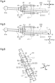
Fig. 2 is a perspective view of the brake pedal device shown inFig. 1 . -
Fig. 3 is a partial front view of the brake pedal device shown inFig. 2 in a state in which a part of a pedal arm is omitted. -
Fig. 4 is a plan view as seen from the direction of arrow A inFig. 1 . -
Fig. 5 is a plan view corresponding toFig. 4 , showing a comparative example. -
Fig. 6 is a partial cross-sectional view taken along line 6-6 inFig. 1 . -
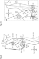
Fig. 7 is a partial side view of the brake pedal device together with the brake booster, in which an operation pedal is depressed from the state shown inFig. 1 . -
Fig. 8 is a partial side view of the brake pedal device according to the embodiment ofFig. 1 , in which an input shaft is being bent by a pressing portion at the time of collision of the vehicle. -
Fig. 9 is a partial side view of the brake pedal device according to the embodiment ofFig. 1 , in which the input shaft is further bent from the state ofFig. 8 . -
Fig. 10 is a partial side view illustrating a lever ratio in the brake pedal device shown inFig. 1 . -
Fig. 11 is a partial side view illustrating a lever ratio in the brake pedal device shown inFig. 1 . -
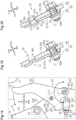
Fig. 12 is a partial cross-sectional view corresponding toFig. 6 , showing a rotation shaft and a shear portion according to a first modification. -
Fig. 13 is a partial cross-sectional view corresponding toFig. 6 , showing a rotation shaft and a shear portion according to a second modification. -
Fig. 14 is a partial side view of a brake pedal device, illustrating advantages of the second modification shown inFig. 13 . -
Fig. 15 is a partial cross-sectional view corresponding toFig. 6 , showing a rotation shaft and a shear portion according to a third modification. -
Fig. 16 is a partial cross-sectional view corresponding toFig. 6 , showing a rotation shaft and a shear portion according to a fourth modification. -
Fig. 17 is a partial cross-sectional view corresponding toFig. 6 , showing a rotation shaft and a shear portion according to a fifth modification. -
Fig. 18 is a side view showing a brake pedal device according to modification in which a rib is formed on a rotation lever. -
Fig. 19 is a cross-sectional view taken along line 19-19 inFig. 18 . -
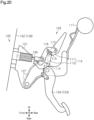
Fig. 20 is a side view showing a brake pedal device of a related art. - A brake pedal device, which is an example of a vehicle operation pedal device, will now be described with reference to
Figs. 1 to 11 . - In the following description, the direction in which a
vehicle 10 advances forward will be referred to as the front, and the reverse direction will be referred to as the rear. The vertical direction refers to the vertical direction of thevehicle 10, and the lateral direction refers to the vehicle width direction that corresponds with the lateral direction when thevehicle 10 is advancing forward. - As shown in
Fig. 1 , thevehicle 10 includes adash panel 12, which is a partition wall. Thedash panel 12 separates apassenger compartment 11 from a portion of avehicle body 15 forward of thepassenger compartment 11; for example, an engine compartment. Aninstrument panel reinforcement 13 and acollision bracket 14, which are vehicle body structural members, are disposed rearward of thedash panel 12. Theinstrument panel reinforcement 13 is a pipe-shaped member extending in the lateral direction to reinforce thevehicle body 15. Thecollision bracket 14 is fixed to a front lower portion of theinstrument panel reinforcement 13. - The
vehicle 10 is provided with abrake device 20 that applies a braking force to wheels (not shown). Thebrake device 20 includes abrake pedal device 21 and abrake booster 40, which is a booster device. - As shown in
Figs. 1 to 3 , thebrake pedal device 21 includes apedal bracket 22 and anoperation pedal 25. Thepedal bracket 22 is fixed directly to thedash panel 12 or to a separate member attached to thedash panel 12. Thepedal bracket 22 includes twoside plate portions 23 disposed in parallel to each other in a state of being spaced apart from each other in the lateral direction. Anoperation shaft 24 extends between the twoside plate portions 23. - The
operation pedal 25 includes apedal arm 26 and apedal pad 28. Thepedal arm 26 is formed from a metal plate. Thepedal arm 26 is shaped to be longer in the vertical direction than in the front-rear direction. Thepedal arm 26 is rotatably supported by thepedal bracket 22 at its upper end via theoperation shaft 24. Thepedal pad 28 is a portion to be depressed by the driver, and is fixed to the lower end of thepedal arm 26. - As shown in
Fig. 1 , the brake booster 40 (booster device) is an example of a device to which the depression force of theoperation pedal 25 is transmitted. Thebrake booster 40 is configured to reduce the amount of depression force applied to theoperation pedal 25, and includes aplunger 41 and aninput shaft 42. Theplunger 41 is movable in the front-rear direction. Theinput shaft 42 includes apush rod 43 and aclevis 44. An axis L1 of thepush rod 43 extends in the front-rear direction and agrees with the axis of theinput shaft 42. Thepush rod 43 has aball portion 43a at the front end. Theball portion 43a is engaged with theplunger 41. Thepush rod 43 is swingable relative to theplunger 41 about theball portion 43a. As shown inFig. 4 , theclevis 44 includes twoside plates 45 arranged parallel to each other with a gap between them in the lateral direction. Theclevis 44 also includes a connectingplate 46, which links the front ends of theside plates 45. In a top view, theclevis 44 forms a U-shape. A connectingpin 47 extends between rear end portions of theside plates 45. A central portion of the connectingplate 46 in the lateral direction is fixed to the rear end of thepush rod 43. This fixation is achieved usingfastening members 48 such as a bolt and a nut. Through this fixation, thepush rod 43 and theclevis 44 are integrated as a single unit. - As shown in
Fig. 1 , thebrake pedal device 21 actuates thebrake booster 40 by moving (pushing) theinput shaft 42 in conjunction with rotation of thepedal arm 26. - The
brake pedal device 21 further includes a rearwardmovement reduction mechanism 50, which includes arotation lever 51, arotation shaft 60, and ashear portion 80. The axis L2 of therotation shaft 60 and the axis L3 of theshear portion 80 both extend in the lateral direction. In the present embodiment, thepedal arm 26 has the same or similar external shape as a pedal arm used in a brake pedal device (not shown) that does not include the rearwardmovement reduction mechanism 50. No significant changes have been made to the shape of the pedal arm due to the addition of the rearwardmovement reduction mechanism 50. - As shown in
Figs. 2 and6 , therotation lever 51 is made of metal such as iron and is formed of a plate having a thickness smaller than that of thepedal arm 26. The lateral direction, which is a direction along the axis L2 of therotation shaft 60, is a thickness direction of therotation lever 51. The core structure of therotation lever 51 is a plate-shaped levermain body 52, which is longer in the vertical direction than in the front-rear direction. As shown inFigs. 1 and2 , the upper end of the levermain body 52 is positioned at about the same height as an intermediate portion of thecollision bracket 14 in the vertical direction. The front lower end of the levermain body 52 is located below theoperation shaft 24. The levermain body 52 is disposed in a state of being overlapped with one side in the thickness direction of thepedal arm 26, that is, on the left side in the present embodiment, but may be disposed in a state of being overlapped with the right side. - The
rotation lever 51 further includes acontact portion 53 and apressing portion 54. Thecontact portion 53 is formed on the rear surface of the upper end of the levermain body 52 at a position forward of thecollision bracket 14. - As shown in
Figs. 2 and4 , thepressing portion 54 protrudes from the front edge of the front lower end of the levermain body 52 toward thepedal arm 26 in the thickness direction of the levermain body 52. In this example, thepressing portion 54 protrudes rightward. Thepressing portion 54 has the shape of a plate that extends vertically. Thepressing portion 54 has a lateral dimension larger than the thickness of the levermain body 52. In the present embodiment, the dimension of thepressing portion 54 in the lateral direction is set to a dimension close to the distance between theside plates 45 of theclevis 44. Thepressing portion 54 is formed integrally with the levermain body 52 by bending the front lower end of the plate used to form the levermain body 52. - As shown in
Figs. 1 and4 , thepressing portion 54 is disposed below theinstrument panel reinforcement 13 and thecollision bracket 14 and above theinput shaft 42. In addition, thepressing portion 54 is disposed such that an intermediate portion thereof in the lateral direction is located above the axis L1. - The
rotation lever 51 is supported by thepedal arm 26 via therotation shaft 60 at a rear lower end of the levermain body 52, the rear lower end being different from thecontact portion 53 and thepressing portion 54. - The
rotation lever 51 rotates about therotation shaft 60 so that thepressing portion 54 presses the connectingplate 46 in a direction intersecting with (in the present embodiment, orthogonal to) the axis L1 when the following condition is met. The condition is that therotation lever 51 receives a load greater than or equal to a predetermined threshold from thecollision bracket 14 when thecontact portion 53 comes into contact with thecollision bracket 14 due to a collision of thevehicle 10. - As shown in
Fig. 6 , in order for therotation lever 51 to be supported by thepedal arm 26 via therotation shaft 60, anarm hole 31 is formed in thepedal arm 26 at a position rearward of theinput shaft 42. Alever hole 55 having a larger diameter than thearm hole 31 is formed in the levermain body 52 at a position rearward of theinput shaft 42. - The
rotation shaft 60 is a metal stepped pin that includes asmall diameter portion 61, alarge diameter portion 62, and aflange 63. Thesmall diameter portion 61 is fitted into thearm hole 31. An end of thesmall diameter portion 61 on the side farther from the lever main body 52 (on the right side) is exposed from thearm hole 31. Anupset portion 64, which is larger in the radial direction than thesmall diameter portion 61, is formed at the exposed end by upsetting the end. Thelarge diameter portion 62 has a larger diameter than thesmall diameter portion 61 and is fitted into thelever hole 55. Thesmall diameter portion 61 is fixed to thepedal arm 26 by sandwiching thepedal arm 26 from the left and right sides by thelarge diameter portion 62 and theupset portion 64. An end of thelarge diameter portion 62 on the side farther from the pedal arm 26 (on the left side) is exposed from thelever hole 55. Theflange 63 is formed at the end of thelarge diameter portion 62, and has a larger diameter than thelever hole 55. Theflange 63 is separated from the levermain body 52 in a direction away from the pedal arm 26 (to the left side) by a gap G1. Therotation shaft 60 has the shear strength to withstand the load received by therotation lever 51 from thecollision bracket 14 during a collision of thevehicle 10 without breaking. - The
shear portion 80 has a function similar to that of what is generally called a shear pin. Specifically, theshear portion 80 fixes therotation lever 51 to thepedal arm 26 when the load applied to therotation lever 51 from thecollision bracket 14 is less than the threshold. When the load applied to therotation lever 51 is greater than or equal to the threshold, theshear portion 80 is broken to cancel the fixation. The fixation by theshear portion 80 refers to restriction of rotation of therotation lever 51 about therotation shaft 60 with respect to thepedal arm 26. This fixation includes not only a state in which therotation lever 51 cannot move in the thickness direction of therotation lever 51 with respect to thepedal arm 26, but also a state in which therotation lever 51 can move in that direction. - In order to allow the
shear portion 80 to exhibit the above-described functionality, anarm hole 32 is formed in thepedal arm 26 by pressing at a position obliquely forward and upward with respect to thearm hole 31. Alever hole 56 having a smaller diameter than thearm hole 32 is formed in the levermain body 52 at a position obliquely forward and upward with respect to thelever hole 55. - The
shear portion 80 is a metal stepped pin including alarge diameter portion 81, aflange 82, and asmall diameter portion 83. Thelarge diameter portion 81 is fitted into thearm hole 32. An end of thelarge diameter portion 81 on the side farther from the lever main body 52 (on the right side) is exposed from thearm hole 32. Theflange 82 is formed at the end of thelarge diameter portion 81 and has a diameter larger than that of thearm hole 32. - The
small diameter portion 83 has a smaller diameter than thelarge diameter portion 81 and is fitted into thelever hole 56. Thesmall diameter portion 83 is formed to have a diameter smaller than that of thesmall diameter portion 61 of therotation shaft 60. By setting the diameters as described above, the shear strength of theshear portion 80 is set to be smaller than the shear strength of therotation shaft 60. An end of thesmall diameter portion 83 on the side farther from the pedal arm 26 (on the left side) is exposed from thelever hole 56. Anupset portion 84, which is larger in the radial direction than thesmall diameter portion 83, is formed at the exposed end by upsetting the end. - From the perspective of ensuring that the
shear portion 80 breaks during a collision of thevehicle 10, it is preferable to use, as theshear portion 80, a straight pin having a relatively small diameter in thelarge diameter portion 81 as well as in thesmall diameter portion 83. This would require the diameter of thearm hole 32 to be relatively small like the diameter of thelever hole 56. Nevertheless, the diameter of thearm hole 32 is made larger than the diameter of thelever hole 56, and a stepped pin is used for the following reason. As described above, the thickness of thepedal arm 26 is greater than the thickness of the levermain body 52. If anarm hole 32 with a small diameter, similar to thelever hole 56, were formed in the relatively thickpedal arm 26, it would be necessary to perform machining (formation of a pilot hole, reaming, chamfering). This would increase the cost of formation. - In contrast, forming the
arm hole 32 through pressing can be done at a lower cost than machining, leading to a reduction in the overall cost of the structure that fixes therotation lever 51 using theshear portion 80. - Further, in the present embodiment, as shown in
Figs. 1 and4 , theinput shaft 42 of thebrake booster 40 is connected to thepedal arm 26. Specifically, thepedal arm 26 includes aclevis hole 27 in a part of the front portion, in the present embodiment, at a position forward of the rotation shaft 60 (arm hole 31). Theclevis hole 27 and its peripheral portion of thepedal arm 26 are disposed between theside plates 45 of theclevis 44. As described above, the connectingpin 47 extending between theside plates 45 is inserted into theclevis hole 27. Thepush rod 43 is connected to thepedal arm 26 by theclevis 44 and the connectingpin 47. -
Fig. 1 shows thebrake pedal device 21 when thevehicle 10 is not in a collision, and theoperation pedal 25 is not being depressed by the driver. Thecontact portion 53 of therotation lever 51 is separated forward from thecollision bracket 14. Theshear portion 80 fixes therotation lever 51 to thepedal arm 26 together with therotation shaft 60 in a state in which the position of therotation lever 51 is determined in the rotation direction around therotation shaft 60. Thepressing portion 54 is separated upward from the connectingplate 46. -
Fig. 7 shows thebrake pedal device 21 when thevehicle 10 is not in a collision, and theoperation pedal 25 is being depressed by the driver, applying force to thepedal pad 28. During this depression operation, theoperation pedal 25 rotates forward around theoperation shaft 24. This rotation is transmitted to thepush rod 43 via the connectingpin 47 and theclevis 44. Thepush rod 43 is moved (pushed forward) so as to actuate thebrake booster 40. Theshear portion 80 fixes therotation lever 51 to thepedal arm 26 together with therotation shaft 60. Therefore, therotation lever 51 moves integrally with theoperation pedal 25 around theoperation shaft 24 at a position away from thecollision bracket 14. Thepressing portion 54 is separated obliquely rearward and upward from the connectingplate 46. - From the state shown in
Fig. 1 , when an external force (impact) is applied to thevehicle body 15 from the front due to a collision of thevehicle 10, thedash panel 12 moves rearward together with thebrake pedal device 21. This reduces the distance between thedash panel 12 and thecollision bracket 14. When therotation lever 51 comes into contact with thecollision bracket 14 at thecontact portion 53, therotation lever 51 receives a load (reaction force) from thecollision bracket 14. This load acts on therotation shaft 60 and theshear portion 80. - When the load received by the
rotation lever 51 from thecollision bracket 14 is greater than or equal to the threshold, theshear portion 80 is broken (cut) due to shearing or similar forms of stress. Therotation shaft 60 is not broken. The fixation of therotation lever 51 to thepedal arm 26 by theshear portion 80 is cancelled. This allows therotation lever 51 to rotate around therotation shaft 60 with respect to thepedal arm 26. - The
rotation lever 51 rotates forward, and thepressing portion 54 comes into contact with the connectingplate 46 from above. As shown inFigs. 8 and9 , thepressing portion 54 presses the connectingplate 46 downward in a direction intersecting with the axis L1 of the push rod 43 (a direction orthogonal to the axis L1 in the present embodiment). This pressing action bends theinput shaft 42 downward. Due to the bending action, theoperation pedal 25, in particular, thepedal pad 28, moves forward, which is the direction of depression of thepedal pad 28. InFigs. 8 and9 , thepedal arm 26 indicated by the long-dash double-short-dash lines indicates the position of thepedal arm 26 before the collision of thevehicle 10. In this manner, the rearward movement of theoperation pedal 25 at the time of collision of thevehicle 10 is reduced. - The present embodiment has the following advantages.
- (1) In the present embodiment, the
input shaft 42 of thebrake booster 40 is connected to thepedal arm 26 as shown inFig. 1 . The phenomenon in which thepush rod 106 connected to the connectingarm 107 of the related art shown inFig. 20 is detached from the connectingarm 107 does not occur in the present embodiment. Further, as shown inFig. 1 , in the present embodiment, even if therotation lever 51 is deformed, the connection state of theinput shaft 42 to thepedal arm 26 is not affected. Therefore, in a non-collision state of thevehicle 10, theinput shaft 42 can be stably moved (pushed) in conjunction with rotation of thepedal arm 26 regardless of the state of therotation lever 51 in the present embodiment. In a non-collision state of thevehicle 10, thebrake booster 40 can be actuated by stably performing the depression operation of theoperation pedal 25 similarly to the brake pedal device not provided with a rearward movement reduction mechanism. - (2) If the vehicle body structural members (the
instrument panel reinforcement 13 and the collision bracket 14) were positioned at the same height as in the present embodiment, the advantage of item (1) would also be obtained by pressing theinput shaft 42 from below with thepressing portion 54. In this case, however, since thepressing portion 54 would need to be located below theinput shaft 42, therotation lever 51 would have a complicated shape and be increased in size. In this regard, in the present embodiment, thepressing portion 54 is disposed below the vehicle body structural member (the collision bracket 14) and above theinput shaft 42 as shown inFig. 1 . Therefore, theinput shaft 42 can be pressed from above by thepressing portion 54, allowing therotation lever 51 to have a simple shape and reduced size. - (3) When the
shear portion 80 is broken upon a collision of thevehicle 10, therotation lever 51 becomes rotatable relative to thepedal arm 26 as described above. In this situation, if theflange 63 of therotation shaft 60 is in contact with the levermain body 52, therotation lever 51 may resist rotation due to sliding resistance between theflange 63 and the levermain body 52. In this regard, in the present embodiment, thesmall diameter portion 61 is fixed to thepedal arm 26 by sandwiching thepedal arm 26 from both left and right sides by thelarge diameter portion 62 and theupset portion 64 as shown inFig. 6 . In this state, theflange 63 is separated from the levermain body 52 by the gap G1. By setting the gap G1, the sliding resistance between theflange 63 and the levermain body 52 is reduced, allowing therotation lever 51 to rotate smoothly. This improves the rearward movement reduction performance of the rearwardmovement reduction mechanism 50. - (4) In the present embodiment, the
pressing portion 54 has the shape of a plate extending in the vertical direction as shown inFigs. 1 to 4 . This configuration increases the strength of thepressing portion 54 in the vertical direction, which is the bending direction of theinput shaft 42. Thepressing portion 54 is thus prevented from being deformed when theinput shaft 42 is bent. By designing the shape of therotation lever 51 in this manner, the strength in the vertical direction of thepressing portion 54 is increased. Thus, there is no need to add separate components for the same purpose. - (5) As shown in
Fig. 5 , a part of the front end of the levermain body 52 that is parallel to the axis L1 of thepush rod 43 may be used as thepressing portion 54. In this case, the dimension of thepressing portion 54 in the lateral direction is the same as the thickness of the levermain body 52. The contact area of thepressing portion 54 with the connectingplate 46 is relatively small. Theinput shaft 42 is swingable about theball portion 43a. Thus, if thepressing portion 54 presses the connectingplate 46 at a position deviated from the axis L1 in the lateral direction, the following concern arises. When that deviated position of the connectingplate 46 is pressed by the small contact area of thepressing portion 54, a force is generated that attempts to rotate theinput shaft 42 around the axis L1, as indicated by arrow B. Thepressing portion 54 presses the connectingplate 46 downward in a state in which the balance in the lateral direction is disrupted. In other words, the pressing force of thepressing portions 54 is used to rotate theinput shaft 42 about the axis L1. Accordingly, the pressing force used to bend theinput shaft 42 is reduced, and the bending efficiency may thus be reduced. - In this regard, in the present embodiment, the dimension of the
pressing portion 54 in the lateral direction is larger than the thickness of the levermain body 52 as shown inFig. 4 . The contact area of thepressing portion 54 with the connectingplate 46 is larger than that of the comparative example ofFig. 5 . Thepressing portion 54 presses the connectingplate 46 downward in a state in which the balance in the lateral direction is maintained. This restricts rotation of theinput shaft 42 about the axis L1. The pressing force of thepressing portion 54 is less likely to be used to rotate theinput shaft 42 about the axis L1. The pressing force of thepressing portion 54 is predominantly used to bend theinput shaft 42, thereby preventing a reduction in bending efficiency. This allows for stable bending of theinput shaft 42. - It is possible to increase the contact area with the connecting
plate 46 by adding another component to therotation lever 51. However, this would increase the number of components. In the present embodiment, since thepressing portion 54, which is a part of therotation lever 51, has a large contact area with the connectingplate 46, it is not necessary to add another component. - (6) In the present embodiment, the
pressing portion 54 is formed by bending a portion (front end) of the plate used to form the levermain body 52 as shown inFig. 4 . In other words, thepressing portion 54 is formed integrally with the levermain body 52. Therefore, a separate member for forming thepressing portion 54 is unnecessary. - (7) The rearward movement reduction mechanism of the related art shown in
Fig. 20 includes the connectingarm 107, the first link 111, thesecond link 113, the first connectingshaft 112, the second connectingshaft 114, the third connectingshaft 115, and therivet shaft 116. The number of parts forming the rearward movement reduction mechanism is large. In particular, there are many shafts for rotation (the first connectingshaft 112 and the second connecting shaft 114). Therefore, the cost of components and the cost required for assembly increase, and the rearward movement reduction mechanism is relatively large in size. - In contrast, in the present embodiment, the rearward
movement reduction mechanism 50 includes a smaller number of components, including therotation lever 51, therotation shaft 60, and theshear portion 80 as shown inFig. 1 . There is only one shaft for rotation (the rotation shaft 60). Further, the levermain body 52, thecontact portion 53, and thepressing portion 54 are formed as a single component. This configuration reduces the cost of components and the cost required for assembly. Furthermore, the compact design of the rearwardmovement reduction mechanism 50 allows for spacesaving optimization. - (8) The rearward
movement reduction mechanism 50 is capable of adjusting the load applied from thecollision bracket 14 to thecontact portion 53 and the force with which thepressing portion 54 bends theinput shaft 42 during a collision of thevehicle 10, by changing the position of at least one of therotation shaft 60 or theshear portion 80. - As shown in
Figs. 10 and11 , the distance from the axis L2 of therotation shaft 60 to thecontact portion 53 is defined as R1. The distance from the axis L2 to the contact point of thepressing portion 54 with the connectingplate 46 is defined as R2. The distance from the axis L2 to the axis L3 of theshear portion 80 is defined as R3. Distances R1 to R3 indicated by solid lines inFig. 10 indicate the distances R1 to R3 in the rearwardmovement reduction mechanism 50 of the present embodiment. - The ratio of the distance R1 to the distance R2 (R1/R2) is referred to as a bending lever ratio. By changing the position of the
rotation shaft 60, at least one of the distances R1 and R2 is changed, and the bending lever ratio (R1/R2) is changed. - By increasing the bending lever ratio (R1/R2), the load applied to the
contact portion 53 is reduced. For example, when the position of therotation shaft 60 is changed obliquely forward and downward, the distance R1 becomes longer and the distance R2 becomes shorter than those in the present embodiment as indicated by the long-dash double-short-dash lines inFig. 10 . Accordingly, the bending lever ratio (R1/R2) increases as compared to that of the present embodiment, and the load applied to thecontact portion 53 decreases. - Conversely, by decreasing the bending lever ratio (R1/R2), the amount by which the
pressing portion 54 bends theinput shaft 42 is increased, enhancing the rearward movement reduction effect. For example, when the position of therotation shaft 60 is changed obliquely rearward and upward, the distance R1 becomes shorter and the distance R2 becomes longer than those in the present embodiment as indicated by the long-dash double-short-dash lines inFig. 11 . Accordingly, the bending lever ratio (R1/R2) decreases as compared to that of the present embodiment, and the amount by which thepressing portion 54 bends theinput shaft 42 increases. - Further, as shown in
Figs. 10 and11 , the ratio of the distance R1 to the distance R3 (R1/R3) is defined as a shear lever ratio. By changing the position of at least one of therotation shaft 60 and theshear portion 80, the distances R1 and R3 are changed, so that the shear lever ratio is changed (R1/R3). - By increasing the shear lever ratio (R1/R3), the load applied to the
contact portion 53 is reduced. For example, when the position of theshear portion 80 is changed downward, the distance R3 becomes shorter than that in the present embodiment as indicated by the broken lines inFig. 11 . Accordingly, the shear lever ratio (R1/R3) increases as compared to that of the present embodiment, and the load applied to thecontact portion 53 decreases. - The rearward
movement reduction mechanism 50 of the present embodiment uses only onerotation shaft 60 as a shaft for rotation as shown inFig. 1 . Therefore, in the present embodiment, it is easy to design the positions of therotation shaft 60 and theshear portion 80. Consequently, it is easy to achieve the optimal settings needed to meet the target values for the rearward movement reduction performance required for the rearwardmovement reduction mechanism 50 in eachvehicle 10. Moreover, the operation of each component of the rearwardmovement reduction mechanism 50 is unlikely to be overly complex. - The rearward movement reduction mechanism of the related art shown in
Fig. 20 can also adopt a similar lever ratio design as the present embodiment. However, the mechanism of the related art uses multiple members (the first connectingshaft 112 and the second connecting shaft 114) as shafts for rotation. Therefore, complex design requirements are imposed, making the design process difficult. Moreover, the operation of each component of the rearward movement reduction mechanism is overly complex. - (9) As shown in
Figs. 1 and6 , thepedal arm 26 of the present embodiment has the same or a similar external shape as the pedal arm in a brake pedal device (not shown) that does not include the rearwardmovement reduction mechanism 50. The shape of the pedal arm has not been significantly altered for the formation of the arm holes 31, 32. Therefore, the size of thepedal arm 26 is not increased due to the addition of the rearwardmovement reduction mechanism 50. - In contrast, in the related art configuration shown in
Fig. 20 , thebrake arm 104 and the connectingarm 107 connected to thebrake arm 104 correspond to thepedal arm 26 of the present embodiment. If thebrake pedal device 100 of the related art did not include the rearward movement reduction mechanism, the connectingarm 107 would have a shape indicated by the long-dash double-short-dash lines inFig. 20 . In order to form portions through which the first connectingshaft 112, the second connectingshaft 114, and therivet shaft 116 are respectively inserted, the connectingarm 107 would need to be expanded upward as shown by the solid lines inFig. 20 . Of thebrake arm 104 and the connectingarm 107, which correspond to thepedal arm 26 of the present embodiment, the size of the connectingarm 107 is increased. - The above-described embodiment may be modified as follows. The above-described embodiment and the following modifications can be combined as long as the combined modifications remain technically consistent with each other.
- In a case in which the lever
main body 52 is a plate longer in the vertical direction than in the front-rear direction as shown inFigs. 18 and 19 , arib 57 extending in the vertical direction may be formed along the rear edge of the levermain body 52. Therib 57 is formed by bending a plate used for forming the levermain body 52 toward one side in the thickness direction, that is, toward the left side inFigs. 18 and 19 . The formation of therib 57 increases the stiffness of therotation lever 51. This configuration prevents therotation lever 51 from being deformed or tilted in the lateral direction even if therotation lever 51 receives a large load from thecollision bracket 14. Additionally, the configuration prevents therotation lever 51 from being deformed due to the reaction force from theinput shaft 42 when theinput shaft 42 is bent by thepressing portion 54. Moreover, it is not necessary to add separate components to increase the stiffness of the levermain body 52, which reduces the cost of therotation lever 51. - The
rib 57 may be formed to extend vertically along the front edge of the levermain body 52 instead of or in addition to the rear edge. Therib 57 may also be formed as a separate member from the levermain body 52. - As shown in
Fig. 5 , a part of the levermain body 52 parallel to the axis L1 of thepush rod 43 may be thepressing portion 54. If thepressing portion 54 protrudes to the left or right from the levermain body 52, the dimension in the lateral direction of thepressing portion 54 may be changed to be larger or smaller than that of the above-described embodiment. - The location at which the
pressing portion 54 presses theclevis 44 may be changed to a location different from the connectingplate 46. Further, the location at which thepressing portion 54 presses theinput shaft 42 may be changed to a location different from theclevis 44. - At least one of the
contact portion 53 and thepressing portion 54 may be formed by a member separate from the levermain body 52. - The
pressing portion 54 may press theinput shaft 42 in a direction obliquely intersecting with the axis L1. - As shown in
Figs. 12 to 17 , therotation shaft 60 and theshear portion 80 may be changed to those having configurations different from those of the above-described embodiment. - In a first modification shown in
Fig. 12 , thearm hole 31 and thelever hole 55 are formed to have the same diameter. Therotation shaft 60 may be a metal straight pin that is fitted into thearm hole 31 and thelever hole 55 and includes ashaft 65 having a uniform diameter and aflange 66. In this case, an end of theshaft 65 on the side farther from the pedal arm 26 (on the left side) is exposed from thelever hole 55. Theflange 66 is formed at the exposed end, and has a larger diameter than thelever hole 55. An end of theshaft 65 on the side farther from the lever main body 52 (on the right side) is exposed from thearm hole 31. Anupset portion 67, which is larger in the radial direction than theshaft 65, is formed at the exposed end by upsetting the end. - Similarly to the above-described embodiment, the
rotation shaft 60 fixes therotation lever 51 to thepedal arm 26 together with theshear portion 80 in a non-collision state of thevehicle 10, and serves as the center of rotation of therotation lever 51 at the time of collision. This also applies to therotation shaft 60 in each of the modifications shown inFigs. 13 to 17 . - In the first modification shown in
Fig. 12 , thearm hole 32 and thelever hole 56 are formed to have the same diameter. Theshear portion 80 may be a metal straight pin that is fitted into thearm hole 32 and thelever hole 56 and includes ashaft 85 having a uniform diameter and aflange 86. In this case, an end of theshaft 85 on the side farther from the pedal arm 26 (on the left side) is exposed from thelever hole 56. Theflange 86 is formed at the exposed end, and has a larger diameter than thelever hole 56. An end of theshaft 85 on the side farther from the lever main body 52 (on the right side) is exposed from thearm hole 32. Anupset portion 87, which is larger in the radial direction than theshaft 85, is formed at the exposed end by upsetting the end. - Similarly to the above-described embodiment, in a non-collision state of the
vehicle 10, theshear portion 80 fixes therotation lever 51 to thepedal arm 26 together with therotation shaft 60 in a state in which the position of therotation lever 51 is determined in the rotation direction around therotation shaft 60. This also applies to each of the modifications shown inFigs. 13 to 15 . - As in a second modification shown in
Fig. 13 , therotation shaft 60 may be formed by a combination of anut 69 and abolt 68 including a head 68a and ashaft 68b. In this case, thearm hole 31 and thelever hole 55 are formed to have the same diameter. Theshaft 68b is inserted through thearm hole 31 and thelever hole 55. The head 68a may be disposed on the opposite side (right side) of thepedal arm 26 from the levermain body 52, or may be disposed on the opposite side (left side) of the levermain body 52 from thepedal arm 26. Thenut 69 is fastened to an end of theshaft 68b on the side opposite to the head 68a. - In the
rotation shaft 60 of the second modification, the distance between thenut 69 and the head 68a of thebolt 68 can be changed. Therefore, even when multiple types ofpedal arms 26 having different thicknesses are used, therotation shaft 60 can be applied to each of thepedal arms 26. By fastening thebolts 68 and the nuts 69, the difference in thickness can be absorbed, and the manufacturing cost will be reduced. - Further, the modification is expected to provide the following advantages. Since, as shown in
Fig. 14 , the rotational direction in which thenut 69 is loosened is the same as the rotational direction of therotation lever 51 when the rearwardmovement reduction mechanism 50 is operated, therotation lever 51 functions as a tool for loosening thenut 69 when the rearwardmovement reduction mechanism 50 operates. Specifically, when therotation lever 51 is rotated forward as indicated by arrow C inFig. 14 , thenut 69 is loosened. InFig. 14 , the counterclockwise direction of the arrow over thenut 69 is the direction in which thenut 69 is loosened, and the clockwise direction of the arrow is the direction in which thenut 69 is tightened. The fastening force by thebolt 68 and thenut 69 is reduced, and therotation lever 51 is easily rotated forward. This improves the rearward movement reduction performance of the rearwardmovement reduction mechanism 50. - The
rotation shaft 60, which includes the combination of thebolt 68 and thenut 69, is also used as therotation shaft 60 in each of the modifications shown inFigs. 15 to 17 . - As shown in
Fig. 13 , theshear portion 80 may include a combination of abolt 88 and anut 89, similarly to therotation shaft 60 inFig. 13 . In this case, thelever hole 56 is formed to have a diameter smaller than that of thearm hole 32 as in the above-described embodiment. Thebolt 88 includes a head 88a, a largediameter shaft portion 88b, and a smalldiameter shaft portion 88c, which has a smaller diameter than the largediameter shaft portion 88b. The head 88a is disposed on the opposite side (right side) of thepedal arm 26 from the levermain body 52. The largediameter shaft portion 88b is inserted through a large portion of thearm hole 32. The smalldiameter shaft portion 88c is inserted through theentire lever hole 56 and a part of thearm hole 32. Thenut 89 is fastened to an end of the smalldiameter shaft portion 88c on the side (left side) opposite to the head 88a. - As in the third modification shown in
Fig. 15 , the levermain body 52 may include acircular protrusion 91 that is formed by plastically deforming a part of the levermain body 52 by pressing, and theprotrusion 91 may be used as theshear portion 80. Theprotrusion 91 is engaged with thearm hole 32. Theshear portion 80 does not sandwich the levermain body 52 and thepedal arm 26 from the left and right sides. However, this does not cause any issues because therotation shaft 60 sandwiches the levermain body 52 and thepedal arm 26 from the left and right sides. - With the third modification, since a part of the lever
main body 52 functions as theshear portion 80, a separate component for fixing such as a stepped pin or a straight pin is not necessary. Further, thelever hole 56 is also unnecessary. In addition, the cost required for forming theshear portion 80 is reduced. - The
protrusion 91 may have an outer shape different from a circular shape. In this case, the shape of thearm hole 32 is changed in accordance with the outer shape of theprotrusion 91. - As in a fourth modification shown in
Fig. 16 , theshear portion 80 may be formed by plastic molding using a plastic. In this case, thearm hole 32 and thelever hole 56 are formed to have the same diameter. Theshear portion 80 includes ashaft 92, aflange 93, and multiple locking lugs 94. Theshaft 92 is fitted in thelever hole 56 and at least a portion of thearm hole 32 adjacent to thelever hole 56. A part of theshaft 92 is inserted into thearm hole 32. An end of theshaft 92 on the side farther from the pedal arm 26 (on the left side) is exposed from thelever hole 56. Theflange 93 is formed at the exposed end, and has a larger diameter than thelever hole 56. The locking lugs 94 extend from the outer circumferential portion of theshaft 92 in a direction away from the lever main body 52 (right side) along the axis L3, and are elastically deformable in the radial direction of theshaft 92. Distal ends of the locking lugs 94 are exposed from thearm hole 32. Each lockinglug 94 includes ahook 94a, which protrudes outward in the radial direction of theshaft 92, in the exposed portion. The distance between theshaft 92 and thehook 94a is less than the thickness of thepedal arm 26. Thehook 94a of each lockinglug 94 is locked to a peripheral portion of thearm hole 32 in thepedal arm 26. - In a case in which the
rotation lever 51 is fixed to thepedal arm 26 by theshear portion 80 of the fourth modification, theshear portion 80 is inserted into thelever hole 56 and thearm hole 32 in that order with thehooks 94a at the leading end. This insertion is performed in a state in which the locking lugs 94 are elastically deformed inward in the radial direction of theshaft 92. When theshear portion 80 is inserted to a position where thehooks 94a are exposed from thearm hole 32, each of the locking lugs 94 is elastically deformed radially outward by an elastic restoring force. Thehook 94a of each lockinglug 94 is locked to a peripheral portion of thearm hole 32 in thepedal arm 26. In this manner, a method of fixing therotation lever 51 to thepedal arm 26 by inserting and locking theshear portion 80 into thelever hole 56 and thearm hole 32 using the elasticity of the locking lugs 94 is also referred to as snap-fit fixing. - The fourth modification facilitates the work of fixing the
rotation lever 51 to thepedal arm 26 using theshear portion 80. In addition, the fourth modification has an advantage in that theshear portion 80 can be formed at a lower cost than in a case in which an iron pin is used as theshear portion 80. - In addition, the portion of the
shaft 92 that extends into thearm hole 32 is used to position therotation lever 51 in the rotational direction around therotation shaft 60. Theshear portion 80 fixes therotation lever 51 to thepedal arm 26 together with therotation shaft 60 in a state in which the positioning is completed. - In a case in which the
shear portion 80 is a pin made of molded plastic, theshear portion 80 can be formed with higher precision than ashear portion 80 that is a protrusion (protrusion 91) produced by pressing shown inFig. 15 . This allows for more stable positioning accuracy. -
Fig. 17 shows a fifth modification, in which apedal arm 26 with a smaller thickness than that used inFig. 16 is employed. Even in this case, since at least a part of theshaft 92 is fitted into thearm hole 32, the positioning function is maintained. In other words, theshear portion 80 of this modification can be applied to various types ofpedal arms 26 with different plate thicknesses. Therefore, it is possible to standardize the component (shear portion 80). - When the
pedal arm 26 having a thickness smaller than that ofFig. 16 is used as shown inFig. 17 , a total value T2 of the thicknesses of thepedal arm 26 and the levermain body 52 is smaller than the distance T1 between theflange 93 and thehook 94a. In a state in which thepedal arm 26 is in contact with thehook 94a and the levermain body 52 is in contact with thepedal arm 26, a gap G2 is created between the levermain body 52 and theflange 93. The gap G2 allows therotation lever 51 to move in a direction along the axis L3 of theshear portion 80. However, the movement is restricted by theflange 93. - In this case, the force with which the
shear portion 80 sandwiches the levermain body 52 and thepedal arm 26 from the left and right sides is relatively small. However, this does not cause any issues because therotation shaft 60 sandwiches the levermain body 52 and thepedal arm 26 from the left and right sides. - In addition, the strength of a plastic product is generally lower than the strength of a product made of metal such as iron. Therefore, even if the
shaft 92 in the modification is made thicker (increased in diameter) than thesmall diameter portion 83 in the above-described embodiment (seeFig. 6 ), theshaft 92 can be broken by shearing or the like. - The combination of the
rotation shaft 60 and theshear portion 80 in the rearwardmovement reduction mechanism 50 may be changed to a combination different from that used in the above-described embodiment and the modifications shown inFigs. 12 to 17 . - The vehicle body structural member with which the
rotation lever 51 comes into contact at the time of collision of thevehicle 10 may be theinstrument panel reinforcement 13 instead of thecollision bracket 14, or may be a separate member that is fixed to theinstrument panel reinforcement 13 and is different from thecollision bracket 14. - The
pedal arm 26 may have a shape different from that of a pedal arm in a brake pedal device (not shown) that is not provided with the rearwardmovement reduction mechanism 50. - The above-described vehicle operation pedal device can be employed in a wide range of applications, such as a booster device to which the depression force of the operation pedal is transmitted. In addition to the
brake pedal device 21, applicable devices include clutch pedal devices and accelerator pedal devices. - The above-described embodiments include configurations described in the following clauses.
- A vehicle operation pedal device employed in a vehicle including a partition wall that partitions a passenger compartment from a portion of a vehicle body forward of the passenger compartment, and a vehicle body structural member disposed behind the partition wall, the vehicle operation pedal device including:
- a pedal bracket fixed to the partition wall;
- an operation pedal that includes a pedal arm rotatably supported by the pedal bracket, in which
- an input shaft of a device to which a depression force of the operation pedal is transmitted is connected to the pedal arm, and
- the operation pedal is configured such that the input shaft is moved in conjunction with rotation of the pedal arm;
- a rotation lever that
- includes a contact portion and a pressing portion,
- is supported by the pedal arm via a rotation shaft, and
- is configured to, by receiving a load greater than or equal to a threshold when the contact portion comes into contact with the vehicle body structural member at a collision of the vehicle, rotate about the rotation shaft such that the pressing portion presses the input shaft in a direction intersecting with an axis of the input shaft; and
- a shear portion that is configured to
fix the rotation lever to the pedal arm when the load applied to the rotation lever from the vehicle body structural member is less than the threshold, and - cancel the fixation by being broken when the load is greater than or equal to the threshold.
- The vehicle operation pedal device according to
clause 1, in which the pressing portion is disposed below the vehicle body structural member and above the input shaft. - The vehicle operation pedal device according to
clause 1 or clause 2, in which - a direction along an axis of the rotation shaft is a thickness direction of the rotation lever, and
- the rotation lever includes:
- a plate-shaped lever main body that is longer in a vertical direction than in a front-rear direction; and
- a rib that extends in the vertical direction along at least one of a front edge or a rear edge of the lever main body.
- The vehicle operation pedal device according to any one of
clauses 1 to 3, in which - the pedal arm includes an arm hole,
- the rotation lever includes a lever hole having a larger diameter than the arm hole,
- the rotation shaft includes:
- a large diameter portion fitted in the lever hole;
- a small diameter portion fitted in the arm hole and fixed to the pedal arm; and
- a flange located at an end of the large diameter portion exposed from the lever hole, the flange having a larger diameter than the lever hole, and
- the flange is separated from the rotation lever in a direction away from the pedal arm.
-
- 10) Vehicle
- 11) Passenger Compartment
- 12) Dash Panel (Partition Wall)
- 13) Instrument Panel Reinforcement (Vehicle Body Structural Member)
- 14) Collision Bracket (Vehicle Body Structural Member)
- 15) Vehicle Body
- 21) Brake Pedal Device (Vehicle Operation Pedal Device)
- 22) Pedal Bracket
- 25) Operation Pedal
- 26) Pedal Arm
- 31, 32) Arm Holes
- 40) Brake Booster (Device to which Depression Force is Transmitted)
- 42) Input Shaft
- 51) Rotation Lever
- 52) Lever Main Body
- 53) Contact Portion
- 54) Pressing Portion
- 55, 56) Lever Holes
- 57) Rib
- 60) Rotation Shaft
- 61) Small Diameter Portion
- 62) Large Diameter Portion
- 63) Flange
- 80) Shear Portion
- L1, L2, L3) Axes
Claims (4)
- A vehicle operation pedal device employed in a vehicle including a partition wall that partitions a passenger compartment from a portion of a vehicle body forward of the passenger compartment, and a vehicle body structural member disposed behind the partition wall, the vehicle operation pedal device comprising:a pedal bracket fixed to the partition wall;an operation pedal that includes a pedal arm rotatably supported by the pedal bracket, whereinan input shaft of a device to which a depression force of the operation pedal is transmitted is connected to the pedal arm, andthe operation pedal is configured such that the input shaft is moved in conjunction with rotation of the pedal arm;a rotation lever thatincludes a contact portion and a pressing portion,is supported by the pedal arm via a rotation shaft, andis configured to, by receiving a load greater than or equal to a threshold when the contact portion comes into contact with the vehicle body structural member at a collision of the vehicle, rotate about the rotation shaft such that the pressing portion presses the input shaft in a direction intersecting with an axis of the input shaft; anda shear portion that is configured tofix the rotation lever to the pedal arm when the load applied to the rotation lever from the vehicle body structural member is less than the threshold, andcancel the fixation by being broken when the load is greater than or equal to the threshold.
- The vehicle operation pedal device according to claim 1, wherein the pressing portion is disposed below the vehicle body structural member and above the input shaft.
- The vehicle operation pedal device according to claim 1, whereina direction along an axis of the rotation shaft is a thickness direction of the rotation lever, andthe rotation lever includes:a plate-shaped lever main body that is longer in a vertical direction than in a front-rear direction; anda rib that extends in the vertical direction along at least one of a front edge or a rear edge of the lever main body.
- The vehicle operation pedal device according to any one of claims 1 to 3, whereinthe pedal arm includes an arm hole,the rotation lever includes a lever hole having a larger diameter than the arm hole,the rotation shaft includes:a large diameter portion fitted in the lever hole;a small diameter portion fitted in the arm hole and fixed to the pedal arm; anda flange located at an end of the large diameter portion exposed from the lever hole, the flange having a larger diameter than the lever hole, andthe flange is separated from the rotation lever in a direction away from the pedal arm.
Applications Claiming Priority (2)
| Application Number | Priority Date | Filing Date | Title |
|---|---|---|---|
| JP2022092267A JP7553506B2 (en) | 2022-06-07 | 2022-06-07 | Vehicle operation pedal device |
| PCT/JP2023/020622 WO2023238787A1 (en) | 2022-06-07 | 2023-06-02 | Operation pedal device for vehicle |
Publications (3)
| Publication Number | Publication Date |
|---|---|
| EP4502756A1 true EP4502756A1 (en) | 2025-02-05 |
| EP4502756A4 EP4502756A4 (en) | 2025-07-23 |
| EP4502756B1 EP4502756B1 (en) | 2026-04-01 |
Family
ID=89118383
Family Applications (1)
| Application Number | Title | Priority Date | Filing Date |
|---|---|---|---|
| EP23819767.7A Active EP4502756B1 (en) | 2022-06-07 | 2023-06-02 | Operation pedal device for vehicle |
Country Status (6)
| Country | Link |
|---|---|
| US (1) | US12393221B2 (en) |
| EP (1) | EP4502756B1 (en) |
| JP (1) | JP7553506B2 (en) |
| CN (1) | CN119137560B (en) |
| WO (1) | WO2023238787A1 (en) |
| ZA (1) | ZA202409124B (en) |
Family Cites Families (19)
| Publication number | Priority date | Publication date | Assignee | Title |
|---|---|---|---|---|
| JP3414023B2 (en) * | 1995-01-27 | 2003-06-09 | トヨタ自動車株式会社 | Brake operating device |
| DE19529347A1 (en) * | 1995-08-09 | 1997-02-20 | Hs Tech & Design | Detachable pedal-mounting in motor vehicle |
| JP3277814B2 (en) * | 1996-06-27 | 2002-04-22 | トヨタ自動車株式会社 | Vehicle pedal displacement control structure |
| JP3781864B2 (en) * | 1997-04-21 | 2006-05-31 | 日産自動車株式会社 | Automotive brake pedal equipment |
| DE69931286T2 (en) | 1998-01-13 | 2006-11-02 | Nissan Motor Co., Ltd., Yokohama | Vehicle brake pedal assembly |
| JP3459346B2 (en) * | 1998-01-13 | 2003-10-20 | 株式会社ヨロズ | Automotive brake pedal structure |
| US6655489B2 (en) * | 2001-04-27 | 2003-12-02 | Mitsubishi Jidosha Kogyo Kabushiki Kaisha | Pedal displacement prevention structure for a vehicle and a vehicle thereof |
| JP4234033B2 (en) * | 2004-02-20 | 2009-03-04 | 本田技研工業株式会社 | Automobile operation pedal device |
| KR20080048279A (en) * | 2006-11-28 | 2008-06-02 | 기아자동차주식회사 | Brake pedal assembly of vehicle |
| KR101220061B1 (en) * | 2006-12-11 | 2013-01-08 | 현대자동차주식회사 | Preventive device of pushed break pedal |
| JP5656113B2 (en) * | 2010-12-15 | 2015-01-21 | スズキ株式会社 | Vehicle pedal device |
| JP5724969B2 (en) * | 2012-08-23 | 2015-05-27 | トヨタ自動車株式会社 | Brake pedal device |
| CN202923569U (en) * | 2012-11-07 | 2013-05-08 | 上海汽车集团股份有限公司 | Intrusion prevention type pedal arm mechanism |
| JP6131810B2 (en) * | 2013-10-01 | 2017-05-24 | トヨタ自動車株式会社 | Brake pedal device for vehicle |
| US9821777B2 (en) * | 2015-02-20 | 2017-11-21 | Toyota Jidosha Kabushiki Kaisha | Vehicle brake pedal device |
| JP6115622B2 (en) * | 2015-02-20 | 2017-04-19 | トヨタ自動車株式会社 | Brake pedal device for vehicle |
| JP6497252B2 (en) * | 2015-07-23 | 2019-04-10 | マツダ株式会社 | Preventing the pedal from moving backward |
| JP2017199199A (en) * | 2016-04-27 | 2017-11-02 | 株式会社アドヴィックス | Vehicle pedal device |
| CN109196445A (en) * | 2016-05-30 | 2019-01-11 | 丰田铁工株式会社 | The anti-locking apparatus of the retrogressing of pedal device for vehicle |
-
2022
- 2022-06-07 JP JP2022092267A patent/JP7553506B2/en active Active
-
2023
- 2023-06-02 CN CN202380036653.2A patent/CN119137560B/en active Active
- 2023-06-02 EP EP23819767.7A patent/EP4502756B1/en active Active
- 2023-06-02 WO PCT/JP2023/020622 patent/WO2023238787A1/en not_active Ceased
- 2023-06-02 US US18/846,274 patent/US12393221B2/en active Active
-
2024
- 2024-11-28 ZA ZA2024/09124A patent/ZA202409124B/en unknown
Also Published As
| Publication number | Publication date |
|---|---|
| CN119137560B (en) | 2025-12-02 |
| JP2023179151A (en) | 2023-12-19 |
| ZA202409124B (en) | 2025-08-27 |
| WO2023238787A1 (en) | 2023-12-14 |
| JP7553506B2 (en) | 2024-09-18 |
| EP4502756A4 (en) | 2025-07-23 |
| CN119137560A (en) | 2024-12-13 |
| US20250103083A1 (en) | 2025-03-27 |
| EP4502756B1 (en) | 2026-04-01 |
| US12393221B2 (en) | 2025-08-19 |
Similar Documents
| Publication | Publication Date | Title |
|---|---|---|
| EP1862363B1 (en) | Brake pedal apparatus for automobile | |
| EP2122433B1 (en) | Vehicle having a pedal support system | |
| JP6577142B2 (en) | Retreat prevention device for vehicle pedal device | |
| US9821777B2 (en) | Vehicle brake pedal device | |
| EP0928726A2 (en) | Brake pedal structure for vehicle | |
| CN113168203B (en) | Vehicle operating pedal device | |
| EP4502756B1 (en) | Operation pedal device for vehicle | |
| JP5650973B2 (en) | Operation pedal support structure | |
| JP6572112B2 (en) | Support structure for vehicle operation pedal | |
| CN113490899B (en) | Operating pedal device for vehicle | |
| JP2006103501A (en) | Backward displacement preventive device for vehicular pedal | |
| JP6148629B2 (en) | Retreat prevention device for vehicle pedal device | |
| EP1659041B1 (en) | Vehicle-pedal backward-displacement preventing device | |
| WO2020012696A1 (en) | Operation pedal device for vehicle | |
| US20180232003A1 (en) | Vehicle operation pedal device | |
| JP3381659B2 (en) | Automotive brake pedal device | |
| JP3962967B2 (en) | Pedal bracket mounting structure | |
| BR112024023953B1 (en) | VEHICLE OPERATION PEDAL DEVICE | |
| JP2020030561A (en) | Operating pedal unit for vehicles | |
| JP2012058801A (en) | Pedal device of vehicle | |
| JP6920258B2 (en) | Vehicle operation pedal device | |
| JP2006315449A (en) | Pedal reverse control device | |
| JP2017219922A (en) | Pedal device for vehicle |
Legal Events
| Date | Code | Title | Description |
|---|---|---|---|
| STAA | Information on the status of an ep patent application or granted ep patent |
Free format text: STATUS: THE INTERNATIONAL PUBLICATION HAS BEEN MADE |
|
| PUAI | Public reference made under article 153(3) epc to a published international application that has entered the european phase |
Free format text: ORIGINAL CODE: 0009012 |
|
| STAA | Information on the status of an ep patent application or granted ep patent |
Free format text: STATUS: REQUEST FOR EXAMINATION WAS MADE |
|
| 17P | Request for examination filed |
Effective date: 20241028 |
|
| AK | Designated contracting states |
Kind code of ref document: A1 Designated state(s): AL AT BE BG CH CY CZ DE DK EE ES FI FR GB GR HR HU IE IS IT LI LT LU LV MC ME MK MT NL NO PL PT RO RS SE SI SK SM TR |
|
| A4 | Supplementary search report drawn up and despatched |
Effective date: 20250624 |
|
| RIC1 | Information provided on ipc code assigned before grant |
Ipc: G05G 1/323 20080401AFI20250617BHEP Ipc: B60T 7/04 20060101ALI20250617BHEP Ipc: B60T 7/06 20060101ALI20250617BHEP Ipc: G05G 1/30 20080401ALI20250617BHEP |
|
| DAV | Request for validation of the european patent (deleted) | ||
| DAX | Request for extension of the european patent (deleted) | ||
| GRAP | Despatch of communication of intention to grant a patent |
Free format text: ORIGINAL CODE: EPIDOSNIGR1 |
|
| STAA | Information on the status of an ep patent application or granted ep patent |
Free format text: STATUS: GRANT OF PATENT IS INTENDED |
|
| INTG | Intention to grant announced |
Effective date: 20251126 |
|
| GRAS | Grant fee paid |
Free format text: ORIGINAL CODE: EPIDOSNIGR3 |
|
| GRAA | (expected) grant |
Free format text: ORIGINAL CODE: 0009210 |
|
| STAA | Information on the status of an ep patent application or granted ep patent |
Free format text: STATUS: THE PATENT HAS BEEN GRANTED |
|
| AK | Designated contracting states |
Kind code of ref document: B1 Designated state(s): AL AT BE BG CH CY CZ DE DK EE ES FI FR GB GR HR HU IE IS IT LI LT LU LV MC ME MK MT NL NO PL PT RO RS SE SI SK SM TR |
|
| REG | Reference to a national code |
Ref country code: CH Ref legal event code: F10 Free format text: ST27 STATUS EVENT CODE: U-0-0-F10-F00 (AS PROVIDED BY THE NATIONAL OFFICE) Effective date: 20260401 Ref country code: GB Ref legal event code: FG4D |
|
| REG | Reference to a national code |
Ref country code: DE Ref legal event code: R096 Ref document number: 602023014648 Country of ref document: DE |
|
| REG | Reference to a national code |
Ref country code: IE Ref legal event code: FG4D |