EP4502743A1 - Machine tool and control device for machine tool - Google Patents
Machine tool and control device for machine tool Download PDFInfo
- Publication number
- EP4502743A1 EP4502743A1 EP23774225.9A EP23774225A EP4502743A1 EP 4502743 A1 EP4502743 A1 EP 4502743A1 EP 23774225 A EP23774225 A EP 23774225A EP 4502743 A1 EP4502743 A1 EP 4502743A1
- Authority
- EP
- European Patent Office
- Prior art keywords
- servo motor
- time constant
- current value
- main spindle
- machine tool
- Prior art date
- Legal status (The legal status is an assumption and is not a legal conclusion. Google has not performed a legal analysis and makes no representation as to the accuracy of the status listed.)
- Pending
Links
Images



Classifications
-
- B—PERFORMING OPERATIONS; TRANSPORTING
- B23—MACHINE TOOLS; METAL-WORKING NOT OTHERWISE PROVIDED FOR
- B23Q—DETAILS, COMPONENTS, OR ACCESSORIES FOR MACHINE TOOLS, e.g. ARRANGEMENTS FOR COPYING OR CONTROLLING; MACHINE TOOLS IN GENERAL CHARACTERISED BY THE CONSTRUCTION OF PARTICULAR DETAILS OR COMPONENTS; COMBINATIONS OR ASSOCIATIONS OF METAL-WORKING MACHINES, NOT DIRECTED TO A PARTICULAR RESULT
- B23Q17/00—Arrangements for observing, indicating or measuring on machine tools
- B23Q17/09—Arrangements for observing, indicating or measuring on machine tools for indicating or measuring cutting pressure or for determining cutting-tool condition, e.g. cutting ability, load on tool
- B23Q17/0952—Arrangements for observing, indicating or measuring on machine tools for indicating or measuring cutting pressure or for determining cutting-tool condition, e.g. cutting ability, load on tool during machining
- B23Q17/0961—Arrangements for observing, indicating or measuring on machine tools for indicating or measuring cutting pressure or for determining cutting-tool condition, e.g. cutting ability, load on tool during machining by measuring power, current or torque of a motor
-
- B—PERFORMING OPERATIONS; TRANSPORTING
- B23—MACHINE TOOLS; METAL-WORKING NOT OTHERWISE PROVIDED FOR
- B23Q—DETAILS, COMPONENTS, OR ACCESSORIES FOR MACHINE TOOLS, e.g. ARRANGEMENTS FOR COPYING OR CONTROLLING; MACHINE TOOLS IN GENERAL CHARACTERISED BY THE CONSTRUCTION OF PARTICULAR DETAILS OR COMPONENTS; COMBINATIONS OR ASSOCIATIONS OF METAL-WORKING MACHINES, NOT DIRECTED TO A PARTICULAR RESULT
- B23Q15/00—Automatic control or regulation of feed movement, cutting velocity or position of tool or work
- B23Q15/007—Automatic control or regulation of feed movement, cutting velocity or position of tool or work while the tool acts upon the workpiece
-
- G—PHYSICS
- G05—CONTROLLING; REGULATING
- G05B—CONTROL OR REGULATING SYSTEMS IN GENERAL; FUNCTIONAL ELEMENTS OF SUCH SYSTEMS; MONITORING OR TESTING ARRANGEMENTS FOR SUCH SYSTEMS OR ELEMENTS
- G05B19/00—Program-control systems
- G05B19/02—Program-control systems electric
- G05B19/18—Numerical control [NC], i.e. automatically operating machines, in particular machine tools, e.g. in a manufacturing environment, so as to execute positioning, movement or co-ordinated operations by means of program data in numerical form
-
- G—PHYSICS
- G05—CONTROLLING; REGULATING
- G05B—CONTROL OR REGULATING SYSTEMS IN GENERAL; FUNCTIONAL ELEMENTS OF SUCH SYSTEMS; MONITORING OR TESTING ARRANGEMENTS FOR SUCH SYSTEMS OR ELEMENTS
- G05B19/00—Program-control systems
- G05B19/02—Program-control systems electric
- G05B19/18—Numerical control [NC], i.e. automatically operating machines, in particular machine tools, e.g. in a manufacturing environment, so as to execute positioning, movement or co-ordinated operations by means of program data in numerical form
- G05B19/416—Numerical control [NC], i.e. automatically operating machines, in particular machine tools, e.g. in a manufacturing environment, so as to execute positioning, movement or co-ordinated operations by means of program data in numerical form characterised by control of velocity, acceleration or deceleration
-
- G—PHYSICS
- G05—CONTROLLING; REGULATING
- G05B—CONTROL OR REGULATING SYSTEMS IN GENERAL; FUNCTIONAL ELEMENTS OF SUCH SYSTEMS; MONITORING OR TESTING ARRANGEMENTS FOR SUCH SYSTEMS OR ELEMENTS
- G05B2219/00—Program-control systems
- G05B2219/30—Nc systems
- G05B2219/43—Speed, acceleration, deceleration control ADC
- G05B2219/43099—Select acceleration deceleration time constants as function of weight, load, position
-
- G—PHYSICS
- G05—CONTROLLING; REGULATING
- G05B—CONTROL OR REGULATING SYSTEMS IN GENERAL; FUNCTIONAL ELEMENTS OF SUCH SYSTEMS; MONITORING OR TESTING ARRANGEMENTS FOR SUCH SYSTEMS OR ELEMENTS
- G05B2219/00—Program-control systems
- G05B2219/30—Nc systems
- G05B2219/43—Speed, acceleration, deceleration control ADC
- G05B2219/43101—Change time constants acceleration, deceleration as function of feed rate override
Definitions
- the present disclosure relates to a machine tool and a control device for a machine tool.
- a machine tool including a main spindle for supporting a workpiece rotatably and a tool for machining the workpiece is generally known.
- a tool driving mechanism of a machine tool is provided with a servo motor, and a tool of the machine tool can be operated by inputting a predetermined current into the servo motor.
- a decrease in power source voltage of a machine tool causes an alarm of excessive error indicating that the actual position of the servo motor differs from a position command value.
- Japanese Patent No. 3252114 stable operation of an electric motor is achieved by executing control to increase or decrease an acceleration/deceleration time constant for adjusting reactivity of acceleration or deceleration of the electric motor, depending on variations in input voltage.
- a limit value of output of a motor that does not adversely affect driving of the motor is calculated based on the voltage of an alternating-current power supply inputted into the motor, and a control parameter for this limitation, which is an acceleration/deceleration time constant or a feed speed override, is determined.
- Variations in power source voltage of a machine tool often result from a driver that drives a main spindle, which consumes the most electric power, and are likely to occur, in particular, at the start of the driver that drives a main spindle.
- control of the acceleration/deceleration time constant of a tool-driving servo motor depending on control of the driver that drives a main spindle is not executed.
- An object of the present disclosure is to provide a machine tool and a control device for a machine tool that can easily avoid issuance of an alarm of excessive error by referring to the state of a driver that drives a main spindle.
- a machine tool includes a driver that drives a main spindle for holding a workpiece rotatably, a servo motor that drives a tool for machining the workpiece held on the main spindle, a power source that supplies electric power to at least the driver and the servo motor, a current detector that detects a current value to be inputted into the servo motor, a storage that stores an upper limit of the current value to be inputted into the servo motor, and a controller that controls the servo motor to execute driving control of the tool.
- the controller When a current value detected by the current detector exceeds the upper limit of the current value immediately after starting the main spindle, the controller changes an acceleration/deceleration time constant from a first time constant to a second time constant that is lower in power consumption than the first time constant, thereby controlling the servo motor.
- the machine tool preferably further includes a voltage detector that detects a source voltage value inputted from the power source.
- a voltage detector that detects a source voltage value inputted from the power source.
- the controller preferably changes the acceleration/deceleration time constant from the first time constant to a third time constant that is lower in power consumption than the first time constant and higher in power consumption than the second time constant, thereby controlling the servo motor.
- a control device for a machine tool is a control device for a machine tool including a driver that drives a main spindle for holding a workpiece rotatably, a servo motor that drives a tool for machining the workpiece held on the main spindle, and a power source that supplies electric power to at least the driver and the servo motor.
- the control device includes a current detector that detects a current value to be inputted into the servo motor, a storage that stores an upper limit of the current value to be inputted into the servo motor, and a controller that controls the servo motor to execute driving control of the tool.
- the controller When a current value detected by the current detector exceeds the upper limit of the current value immediately after starting the main spindle, the controller changes an acceleration/deceleration time constant from a first time constant to a second time constant that is lower in power consumption than the first time constant, thereby controlling the servo motor.
- the control device for a machine tool preferably further includes a voltage detector that detects a source voltage value inputted from the power source.
- a voltage detector that detects a source voltage value inputted from the power source.
- the controller preferably changes the acceleration/deceleration time constant from the first time constant to a third time constant that is lower in power consumption than the first time constant and higher in power consumption than the second time constant, thereby controlling the servo motor.
- a machine tool and a control device for a machine tool that can easily avoid issuance of an alarm of excessive error by referring to the state of a driver that drives a main spindle are provided according to an embodiment of the present disclosure.
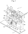
- FIG. 1 is a partial perspective view of a machine tool 1 according to the present embodiment.
- the machine tool 1 shown in FIG. 1 is a device for machining a workpiece W that is a long round bar.
- the machine tool 1 includes a main spindle 2 for supporting the workpiece W rotatably, a rotary tool driver 13 including a B-axis rotary tool device 3, and a numerically controlled (NC) device 5, which will be described below.
- NC numerically controlled
- the main spindle 2 is provided on a support 6.
- the main spindle 2 whose axis is in the Z-axis direction, holds the workpiece W rotatably about the Z-axis, and can move the workpiece W toward the front side of the support 6 by motive power generated by a main-spindle motor (fourth servo motor) MT4 constituting a driver DU.
- the support 6 is fixed and supported by a bed 7.
- On the front side of the support 6 are installed rails 8 extending along the X-axis direction (also referred to as the horizontal direction) perpendicular to the Z-axis direction.
- On the rails 8 is mounted a base 10 that slides in the direction of arrow ⁇ 1 by motive power generated by a first servo motor MT1.
- On the base 10 are installed rails 11 extending along the Y-axis direction (also referred to as the vertical direction) perpendicular to the Z-axis and X-axis directions.
- On the rails 11 is mounted the rotary tool driver 13 that slides in the direction of arrow ⁇ 2 by motive power generated by a second servo motor MT2.
- the rotary tool driver 13 holds tools for machining the workpiece W.
- the rotary tool driver 13 includes tools 131 and 132 as well as the B-axis rotary tool device 3 including a first tool 31 and a second tool 32.
- the tools 131 and 132 are installed side by side along the X-axis direction with their tips facing downward.
- the first tool 31 and the second tool 32 are rotatably held by a B-axis rotary tool body 33 constituting the B-axis rotary tool device 3, and are installed side by side along the X-axis direction with their tips facing sideward.
- the machine tool 1 can machine the workpiece W with a predetermined tool by moving the workpiece W in the Z-axis direction with the main spindle 2 and moving the rotary tool driver 13 in the direction of arrow ⁇ 1 or ⁇ 2 .
- the B-axis rotary tool body 33 is supported so as to be capable of turning in the direction of arrow ⁇ 3 around a pivot A of a turning motor (third servo motor) MT3 by motive power generated by the turning motor MT3.
- the servo motors MT1 to MT4 provided in the machine tool 1 run by electric power supplied from a power source PS.
- the power source PS converts electric power supplied from a home or commercial power source into electric power usable in the machine tool 1 according to the present embodiment, and supplies the converted electric power at least to the servo motors MT1 to MT4.
- FIG. 2 is a block diagram showing the internal configuration of the machine tool 1 shown in FIG. 1 .
- the B-axis rotary tool device 3 includes the B-axis rotary tool body 33, a horizontal-direction moving mechanism M1, the first servo motor MT1, a vertical-direction moving mechanism M2, the second servo motor MT2, a turning mechanism M3, and the turning motor MT3.
- the horizontal-direction moving mechanism M1 enables the whole rotary tool driver 13 including the B-axis rotary tool body 33 to move in the direction of arrow ⁇ 1 .
- the first servo motor MT1 converts an inputted current into mechanical output (motive power such as torque and rpm), and gives the output to the horizontal-direction moving mechanism M1. In this way, the horizontal-direction moving mechanism M1 moves the B-axis rotary tool body 33 forward and backward in the direction of arrow ⁇ 1 . Operation of the first servo motor MT1 is controlled by a motion controller C1.
- the motion controller C1 is supplied with electric power by the power source PS to input a predetermined current into the first servo motor MT1, depending on a control signal transmitted from the NC device 5 described below.
- a control signal transmitted to the motion controller C1 includes at least the amount of rotation (radian or the number of steps) and the number of revolutions (rpm) of the first servo motor MT1.
- the first servo motor MT1 is provided with a sensor Se1, which detects the actual amount of rotation and the actual number of revolutions of the first servo motor MT1 and transmits them to the motion controller C1.
- the motion controller C1 compares the values of the amount of rotation and the number of revolutions of the first servo motor MT1 included in a control signal with the values of the actual amount of rotation and the actual number of revolutions of the first servo motor MT1 detected by the sensor Se1, and inputs a predetermined current into the first servo motor MT1 so as to reduce the differences between these values to zero. Since the methods of controlling motion controllers C2 to C4 are similar to that of controlling the motion controller C1, a detailed description thereof is omitted.
- the vertical-direction moving mechanism M2 enables the whole rotary tool driver 13 including the B-axis rotary tool body 33 to move upward and downward in the direction of arrow ⁇ 2 .
- the second servo motor MT2 generates motive power for operating the vertical-direction moving mechanism M2. Operation of the second servo motor MT2 is controlled by the motion controller C2. Since the method of the motion controller C2 controlling the second servo motor MT2 is similar to that of the motion controller C1 controlling the first servo motor MT1, a detailed description thereof is omitted.
- the turning mechanism M3 enables the B-axis rotary tool body 33 to turn in the direction of arrow ⁇ 3 around the pivot A of the turning motor MT3.
- the turning motor MT3 generates motive power for operating the turning mechanism M3. Operation of the turning motor MT3 is controlled by the motion controller C3. Since the method of the motion controller C3 controlling the turning motor MT3 is similar to that of the motion controller C1 controlling the first servo motor MT1, a detailed description thereof is omitted.
- the main spindle 2 includes a main-spindle driving mechanism M4 and the main-spindle motor MT4 that constitute the driver DU.
- the main-spindle driving mechanism M4 whose axis is in the Z-axis direction, supports the workpiece W rotatably about the Z-axis, and can move the workpiece W toward the front side of the support 6 by motive power generated by the main-spindle motor MT4.
- the main-spindle motor MT4 generates motive power for operating the main-spindle driving mechanism M4. Operation of the main-spindle motor MT4 is controlled by the motion controller C4.
- the main-spindle motor MT4 may be any motor rotating stably other than a servo motor.
- the NC device 5 controls operation of the main spindle 2 and the B-axis rotary tool device 3.
- the NC device 5 includes an interface unit 51, a storage 52, an input unit 53, an output unit 54, a current detector 55, a voltage detector 56, and a controller 57.
- the interface unit 51, the storage 52, the input unit 53, the output unit 54, the current detector 55, the voltage detector 56, and the controller 57 are connected to each other via a bus 58.
- Various control signals from the controller 57 are transmitted to the motion controllers C1 to C5 via the interface unit 51.
- Current values outputted from the motion controllers C1 to C4 to the corresponding servo motors MT1 to MT4 are transmitted to the current detector 55 via the interface unit 51.
- the storage 52 includes, for example, a semiconductor memory, and stores programs and data used for processing by the controller 57.
- the storage 52 stores at least a program executed by the controller 57 to cause the main spindle 2 and the B-axis rotary tool device 3 to perform a series of workpiece machining steps.
- the program may be installed on the storage 52 from a computer-readable portable storage medium, such as a CD-ROM, with a known set-up program.
- the storage 52 prestores an upper limit of the current values to be inputted into the servo motors MT1 to MT4 from the motion controllers C1 to C4.
- the upper limit is a current value at which there is a risk of a breakdown of a servo motor.
- the input unit 53 may be any known device that enables input of data, and generates a signal corresponding to operation by an operator of the machine tool 1.
- the generated signal is supplied to the controller 57 as the operator's instruction.
- the output unit 54 may be any known device that can display video and images, and displays video and images depending on video data or image data supplied from the controller 57.
- the current detector 55 detects current values to be inputted into the servo motors MT1 to MT4 from the motion controllers C1 to C4, and transmits the results of detection to the controller 57.
- the voltage detector 56 detects a source voltage value inputted from the power source PS into the main spindle 2 and the B-axis rotary tool device 3, and transmits the result of detection to the controller 57.
- the controller 57 centrally controls the entire operation of the machine tool 1, and is, for example, a central processing unit (CPU).
- the controller 57 causes a series of workpiece machining steps to be performed, in accordance with a program stored in the storage 52.
- the controller 57 transmits control signals for a series of workpiece machining steps to be performed to the motion controllers C1 to C4 via the interface unit 51, thereby controlling the servo motors MT1 to MT4 to execute driving control of the tools.
- the control signals include the amounts of rotation (radians or the numbers of steps) and the numbers of revolutions (rpm) of the servo motors.
- FIG. 3 is a flowchart showing a series of workpiece machining steps performed by the machine tool 1 according to the present embodiment.
- the controller 57 When an instruction to machine a workpiece is inputted by a predetermined procedure, the controller 57 first executes control of operation of the main spindle 2 in accordance with a program stored in the storage 52 (step S10). More specifically, the controller 57 transmits a predetermined control signal including the amount of rotation (radian or the number of steps) and the number of revolutions (rpm) of the main-spindle motor MT4 to the motion controller C4 via the interface unit 51. The motion controller C4 controls the main-spindle motor MT4, depending on the control signal transmitted from the controller 57, to drive the main-spindle driving mechanism M4, thereby rotating the workpiece W about the Z-axis and moving the workpiece W toward the front side of the support 6.
- the controller 57 executes control of operation of the tools (step S11). More specifically, the controller 57 controls at least one of the servo motors MT1 and MT2 to move the B-axis rotary tool device 3, thereby moving the B-axis rotary tool body 33 in the direction of arrow ⁇ 1 or ⁇ 2 .
- This enables the machine tool 1 according to the present embodiment to push the tools 131 and 132 as well as the first tool 31 and the second tool 32 against the rotating workpiece W to machine the workpiece W.
- step S12 determines whether the series of workpiece machining steps is finished.
- the process returns to step S10.
- the series of workpiece machining steps is finished (Yes in step S12)
- the series of workpiece machining steps is finished.
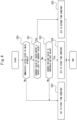
- FIG. 4 is a flowchart showing a process of determining the time constant of the second servo motor MT2 in the series of workpiece machining steps shown in FIG. 3 .
- the process shown in FIG. 4 is executed at regular intervals in the series of workpiece machining steps shown in FIG. 3 .
- FIG. 4 illustrates a process on the second servo motor MT2 as an example, but similar processes may also be executed on the other servo motors MT1 and MT3.
- the controller 57 determines whether the current time is immediately after the start of the main spindle 2 (step S20).
- the time immediately after the start of the main spindle 2 refers to a period from input into the motion controller C4 of a control signal to start the main spindle 2 rotating until the main spindle 2 starts operating at its rating.
- the controller sets the acceleration/deceleration time constant to a first time constant (step S23) and terminates the process.
- step S20 the controller 57 determines whether the current value supplied to the second servo motor MT2 detected by the current detector 55 exceeds the upper limit of the current value stored in the storage 52 (step S21).
- step S21 the controller 57 sets the acceleration/deceleration time constant to a second time constant (step S25) and terminates the process.
- the controller 57 determines whether the source voltage value of the power source PS detected by the voltage detector 56 is equal to or less than a threshold voltage value (i.e., whether a voltage drop has occurred in the power source PS) (step S22).
- a threshold voltage value i.e., whether a voltage drop has occurred in the power source PS.
- the controller 57 sets the acceleration/deceleration time constant to the first time constant (step S23) and terminates the process.
- step S22 when the source voltage value of the power source PS is equal to or less than the threshold voltage value (Yes in step S22), there is no risk of a breakdown of the second servo motor MT2, but a voltage drop has occurred in the power source PS.
- the controller 57 sets the acceleration/deceleration time constant to a third time constant (step S24) and terminates the process.
- the acceleration/deceleration time constant is a value corresponding to the time until the rotation speed of the servo motor reaches a set rotation speed.
- the first time constant corresponds to the shortest time until the rotation speed of the second servo motor MT2 reaches the set rotation speed during normal operation.
- the time until the rotation speed of the second servo motor MT2 reaches the set rotation speed is longer than at the first time constant, and thus the power consumption per unit time of the second servo motor MT2 is lower than at the first time constant.
- the time until the rotation speed of the second servo motor MT2 reaches the set rotation speed is longer than at the first time constant and shorter than at the second time constant, and thus the power consumption per unit time of the second servo motor MT2 is lower than at the first time constant and higher than at the second time constant.
- the time constant of the second servo motor MT2 is set to the first time constant except immediately after the start of the main spindle 2, and to one of the first to third time constants immediately after the start of the main spindle 2, depending on the current value of the second servo motor MT2 and the source voltage value.
- FIG. 5 is a waveform chart showing examples of time-varying changes in the rotation speed of the second servo motor MT2 that depend on the current value control shown in FIG. 4 .
- the abscissa represents time (time t 1 to t 3 ) (ms), and the ordinate represents the rotation speed (r/min) of the servo motor.
- the controller 57 When controlling the second servo motor MT2 in the series of workpiece machining steps shown in FIG. 3 , the controller 57 generates a control signal based on the time constant that is currently set, and transmits the signal to the motion controller C2.
- the motion controller C2 adjusts the current value to be inputted into the second servo motor MT2, depending on the transmitted control signal. This enables the machine tool 1 according to the present embodiment to operate the second servo motor MT2, regardless of variations in the inputted voltage value and the source voltage value.
- the solid line 61 in FIG. 5 indicates time-varying changes in the rotation speed of the second servo motor MT2 corresponding to the first time constant.
- the dashed line 63 in FIG. 5 indicates time-varying changes in the rotation speed of the second servo motor MT2 corresponding to the third time constant.
- the second time constant When the second time constant is set, the number of revolutions of the second servo motor MT2 need not be increased as rapidly as when the first time constant is set, and thus the supplied current value will not exceed the upper limit of the current value. As a result, when the second time constant is set, the possibility of a breakdown of the second servo motor MT2 and issuance of an alarm of excessive error is lower than when the first time constant is set. Similarly, when the third time constant is set, the number of revolutions of the second servo motor MT2 can be increased slower than when the first time constant is set, and thus the supplied current value will not exceed the upper limit of the current value. As a result, when the third time constant is set, the possibility of a breakdown of the second servo motor MT2 and issuance of an alarm of excessive error is much lower than when the first time constant is set.
- the second servo motor MT2 is taken as an example, but the same holds true for the other servo motors MT1 and MT3.
- time constants are used as the acceleration/deceleration time constant, but one of two or four or more time constants may be set depending on parameters such as the current value of a servo motor and the source voltage value of the power source PS.
- the servo motors MT1 to MT4 that operate the main spindle 2 and the B-axis rotary tool device 3 have been mainly described, but the above-described control is also applicable to another servo motor that differs from those described above, such as one that drives a tool.
Landscapes
- Engineering & Computer Science (AREA)
- Mechanical Engineering (AREA)
- Human Computer Interaction (AREA)
- Manufacturing & Machinery (AREA)
- Physics & Mathematics (AREA)
- General Physics & Mathematics (AREA)
- Automation & Control Theory (AREA)
- Numerical Control (AREA)
Abstract
Description
- The present disclosure relates to a machine tool and a control device for a machine tool.
- A machine tool including a main spindle for supporting a workpiece rotatably and a tool for machining the workpiece is generally known. A tool driving mechanism of a machine tool is provided with a servo motor, and a tool of the machine tool can be operated by inputting a predetermined current into the servo motor.
- A decrease in power source voltage of a machine tool causes an alarm of excessive error indicating that the actual position of the servo motor differs from a position command value.
- In
Japanese Patent No. 3252114 Japanese Patent No. 5149410 - Variations in power source voltage of a machine tool often result from a driver that drives a main spindle, which consumes the most electric power, and are likely to occur, in particular, at the start of the driver that drives a main spindle. However, control of the acceleration/deceleration time constant of a tool-driving servo motor depending on control of the driver that drives a main spindle is not executed.
- An object of the present disclosure is to provide a machine tool and a control device for a machine tool that can easily avoid issuance of an alarm of excessive error by referring to the state of a driver that drives a main spindle.
- A machine tool according to an embodiment of the present disclosure includes a driver that drives a main spindle for holding a workpiece rotatably, a servo motor that drives a tool for machining the workpiece held on the main spindle, a power source that supplies electric power to at least the driver and the servo motor, a current detector that detects a current value to be inputted into the servo motor, a storage that stores an upper limit of the current value to be inputted into the servo motor, and a controller that controls the servo motor to execute driving control of the tool. When a current value detected by the current detector exceeds the upper limit of the current value immediately after starting the main spindle, the controller changes an acceleration/deceleration time constant from a first time constant to a second time constant that is lower in power consumption than the first time constant, thereby controlling the servo motor.
- The machine tool according to an embodiment of the present disclosure preferably further includes a voltage detector that detects a source voltage value inputted from the power source. When the current value detected by the current detector is equal to or less than the upper limit of the current value and the source voltage value detected by the voltage detector is equal to or less than a threshold voltage value immediately after starting the main spindle, the controller preferably changes the acceleration/deceleration time constant from the first time constant to a third time constant that is lower in power consumption than the first time constant and higher in power consumption than the second time constant, thereby controlling the servo motor.
- A control device for a machine tool according to an embodiment of the present disclosure is a control device for a machine tool including a driver that drives a main spindle for holding a workpiece rotatably, a servo motor that drives a tool for machining the workpiece held on the main spindle, and a power source that supplies electric power to at least the driver and the servo motor. The control device includes a current detector that detects a current value to be inputted into the servo motor, a storage that stores an upper limit of the current value to be inputted into the servo motor, and a controller that controls the servo motor to execute driving control of the tool. When a current value detected by the current detector exceeds the upper limit of the current value immediately after starting the main spindle, the controller changes an acceleration/deceleration time constant from a first time constant to a second time constant that is lower in power consumption than the first time constant, thereby controlling the servo motor.
- The control device for a machine tool according to an embodiment of the present disclosure preferably further includes a voltage detector that detects a source voltage value inputted from the power source. When the current value detected by the current detector is equal to or less than the upper limit of the current value and the source voltage value detected by the voltage detector is equal to or less than a threshold voltage value immediately after starting the main spindle, the controller preferably changes the acceleration/deceleration time constant from the first time constant to a third time constant that is lower in power consumption than the first time constant and higher in power consumption than the second time constant, thereby controlling the servo motor.
- A machine tool and a control device for a machine tool that can easily avoid issuance of an alarm of excessive error by referring to the state of a driver that drives a main spindle are provided according to an embodiment of the present disclosure.
-
-
FIG. 1 is a partial perspective view of a machine tool according to the embodiment; -
FIG. 2 is a block diagram showing the internal configuration of the machine tool shown inFIG. 1 ; -
FIG. 3 is a flowchart showing a series of workpiece machining steps performed by the machine tool according to the embodiment; -
FIG. 4 is a flowchart showing a process of determining the time constant of a servo motor in the series of workpiece machining steps shown inFIG. 3 ; and -
FIG. 5 is a waveform chart showing examples of time-varying changes in the rotation speed of a servo motor that depend on the current value control shown inFIG. 4 . - A machine tool according to the present embodiment will now be described with reference to the attached drawings. However, note that the technical scope of the present disclosure is not limited to embodiments thereof and covers the invention described in the claims and equivalents thereof.
-
FIG. 1 is a partial perspective view of a machine tool 1 according to the present embodiment. The machine tool 1 shown inFIG. 1 is a device for machining a workpiece W that is a long round bar. The machine tool 1 includes amain spindle 2 for supporting the workpiece W rotatably, arotary tool driver 13 including a B-axisrotary tool device 3, and a numerically controlled (NC)device 5, which will be described below. - The
main spindle 2 is provided on asupport 6. Themain spindle 2, whose axis is in the Z-axis direction, holds the workpiece W rotatably about the Z-axis, and can move the workpiece W toward the front side of thesupport 6 by motive power generated by a main-spindle motor (fourth servo motor) MT4 constituting a driver DU. Thesupport 6 is fixed and supported by abed 7. - On the front side of the
support 6 are installedrails 8 extending along the X-axis direction (also referred to as the horizontal direction) perpendicular to the Z-axis direction. On therails 8 is mounted abase 10 that slides in the direction of arrow α1 by motive power generated by a first servo motor MT1. On thebase 10 are installedrails 11 extending along the Y-axis direction (also referred to as the vertical direction) perpendicular to the Z-axis and X-axis directions. On therails 11 is mounted therotary tool driver 13 that slides in the direction of arrow α2 by motive power generated by a second servo motor MT2. - The
rotary tool driver 13 holds tools for machining the workpiece W. Therotary tool driver 13 includestools rotary tool device 3 including afirst tool 31 and asecond tool 32. Thetools first tool 31 and thesecond tool 32 are rotatably held by a B-axisrotary tool body 33 constituting the B-axisrotary tool device 3, and are installed side by side along the X-axis direction with their tips facing sideward. The machine tool 1 according to the present embodiment can machine the workpiece W with a predetermined tool by moving the workpiece W in the Z-axis direction with themain spindle 2 and moving therotary tool driver 13 in the direction of arrow α1 or α2. The B-axisrotary tool body 33 is supported so as to be capable of turning in the direction of arrow α3 around a pivot A of a turning motor (third servo motor) MT3 by motive power generated by the turning motor MT3. - The servo motors MT1 to MT4 provided in the machine tool 1 run by electric power supplied from a power source PS. The power source PS converts electric power supplied from a home or commercial power source into electric power usable in the machine tool 1 according to the present embodiment, and supplies the converted electric power at least to the servo motors MT1 to MT4.
-
FIG. 2 is a block diagram showing the internal configuration of the machine tool 1 shown inFIG. 1 . As shown inFIG. 2 , the B-axisrotary tool device 3 includes the B-axisrotary tool body 33, a horizontal-direction moving mechanism M1, the first servo motor MT1, a vertical-direction moving mechanism M2, the second servo motor MT2, a turning mechanism M3, and the turning motor MT3. - The horizontal-direction moving mechanism M1 enables the whole
rotary tool driver 13 including the B-axisrotary tool body 33 to move in the direction of arrow α1. The first servo motor MT1 converts an inputted current into mechanical output (motive power such as torque and rpm), and gives the output to the horizontal-direction moving mechanism M1. In this way, the horizontal-direction moving mechanism M1 moves the B-axisrotary tool body 33 forward and backward in the direction of arrow α1. Operation of the first servo motor MT1 is controlled by a motion controller C1. - The motion controller C1 is supplied with electric power by the power source PS to input a predetermined current into the first servo motor MT1, depending on a control signal transmitted from the
NC device 5 described below. A control signal transmitted to the motion controller C1 includes at least the amount of rotation (radian or the number of steps) and the number of revolutions (rpm) of the first servo motor MT1. The first servo motor MT1 is provided with a sensor Se1, which detects the actual amount of rotation and the actual number of revolutions of the first servo motor MT1 and transmits them to the motion controller C1. The motion controller C1 compares the values of the amount of rotation and the number of revolutions of the first servo motor MT1 included in a control signal with the values of the actual amount of rotation and the actual number of revolutions of the first servo motor MT1 detected by the sensor Se1, and inputs a predetermined current into the first servo motor MT1 so as to reduce the differences between these values to zero. Since the methods of controlling motion controllers C2 to C4 are similar to that of controlling the motion controller C1, a detailed description thereof is omitted. - The vertical-direction moving mechanism M2 enables the whole
rotary tool driver 13 including the B-axisrotary tool body 33 to move upward and downward in the direction of arrow α2. The second servo motor MT2 generates motive power for operating the vertical-direction moving mechanism M2. Operation of the second servo motor MT2 is controlled by the motion controller C2. Since the method of the motion controller C2 controlling the second servo motor MT2 is similar to that of the motion controller C1 controlling the first servo motor MT1, a detailed description thereof is omitted. - The turning mechanism M3 enables the B-axis
rotary tool body 33 to turn in the direction of arrow α3 around the pivot A of the turning motor MT3. The turning motor MT3 generates motive power for operating the turning mechanism M3. Operation of the turning motor MT3 is controlled by the motion controller C3. Since the method of the motion controller C3 controlling the turning motor MT3 is similar to that of the motion controller C1 controlling the first servo motor MT1, a detailed description thereof is omitted. - As shown in
FIG. 2 , themain spindle 2 includes a main-spindle driving mechanism M4 and the main-spindle motor MT4 that constitute the driver DU. The main-spindle driving mechanism M4, whose axis is in the Z-axis direction, supports the workpiece W rotatably about the Z-axis, and can move the workpiece W toward the front side of thesupport 6 by motive power generated by the main-spindle motor MT4. The main-spindle motor MT4 generates motive power for operating the main-spindle driving mechanism M4. Operation of the main-spindle motor MT4 is controlled by the motion controller C4. Since the method of the motion controller C4 controlling the main-spindle motor MT4 is similar to that of the motion controller C1 controlling the first servo motor MT1, a detailed description thereof is omitted. The main-spindle motor MT4 may be any motor rotating stably other than a servo motor. - The
NC device 5 controls operation of themain spindle 2 and the B-axisrotary tool device 3. As shown inFIG. 2 , theNC device 5 includes aninterface unit 51, astorage 52, aninput unit 53, anoutput unit 54, acurrent detector 55, avoltage detector 56, and acontroller 57. Theinterface unit 51, thestorage 52, theinput unit 53, theoutput unit 54, thecurrent detector 55, thevoltage detector 56, and thecontroller 57 are connected to each other via abus 58. Various control signals from thecontroller 57 are transmitted to the motion controllers C1 to C5 via theinterface unit 51. Current values outputted from the motion controllers C1 to C4 to the corresponding servo motors MT1 to MT4 are transmitted to thecurrent detector 55 via theinterface unit 51. - The
storage 52 includes, for example, a semiconductor memory, and stores programs and data used for processing by thecontroller 57. Thestorage 52 stores at least a program executed by thecontroller 57 to cause themain spindle 2 and the B-axisrotary tool device 3 to perform a series of workpiece machining steps. The program may be installed on thestorage 52 from a computer-readable portable storage medium, such as a CD-ROM, with a known set-up program. - Further, the
storage 52 prestores an upper limit of the current values to be inputted into the servo motors MT1 to MT4 from the motion controllers C1 to C4. The upper limit is a current value at which there is a risk of a breakdown of a servo motor. - The
input unit 53 may be any known device that enables input of data, and generates a signal corresponding to operation by an operator of the machine tool 1. The generated signal is supplied to thecontroller 57 as the operator's instruction. - The
output unit 54 may be any known device that can display video and images, and displays video and images depending on video data or image data supplied from thecontroller 57. - The
current detector 55 detects current values to be inputted into the servo motors MT1 to MT4 from the motion controllers C1 to C4, and transmits the results of detection to thecontroller 57. Thevoltage detector 56 detects a source voltage value inputted from the power source PS into themain spindle 2 and the B-axisrotary tool device 3, and transmits the result of detection to thecontroller 57. - The
controller 57 centrally controls the entire operation of the machine tool 1, and is, for example, a central processing unit (CPU). Thecontroller 57 causes a series of workpiece machining steps to be performed, in accordance with a program stored in thestorage 52. Thecontroller 57 transmits control signals for a series of workpiece machining steps to be performed to the motion controllers C1 to C4 via theinterface unit 51, thereby controlling the servo motors MT1 to MT4 to execute driving control of the tools. The control signals include the amounts of rotation (radians or the numbers of steps) and the numbers of revolutions (rpm) of the servo motors. -
FIG. 3 is a flowchart showing a series of workpiece machining steps performed by the machine tool 1 according to the present embodiment. - When an instruction to machine a workpiece is inputted by a predetermined procedure, the
controller 57 first executes control of operation of themain spindle 2 in accordance with a program stored in the storage 52 (step S10). More specifically, thecontroller 57 transmits a predetermined control signal including the amount of rotation (radian or the number of steps) and the number of revolutions (rpm) of the main-spindle motor MT4 to the motion controller C4 via theinterface unit 51. The motion controller C4 controls the main-spindle motor MT4, depending on the control signal transmitted from thecontroller 57, to drive the main-spindle driving mechanism M4, thereby rotating the workpiece W about the Z-axis and moving the workpiece W toward the front side of thesupport 6. - Next, the
controller 57 executes control of operation of the tools (step S11). More specifically, thecontroller 57 controls at least one of the servo motors MT1 and MT2 to move the B-axisrotary tool device 3, thereby moving the B-axisrotary tool body 33 in the direction of arrow α1 or α2. This enables the machine tool 1 according to the present embodiment to push thetools first tool 31 and thesecond tool 32 against the rotating workpiece W to machine the workpiece W. - Finally, the
controller 57 determines whether the series of workpiece machining steps is finished (step S12). When the workpiece machining steps are not finished (No in step S12), the process returns to step S10. When the series of workpiece machining steps is finished (Yes in step S12), the series of workpiece machining steps is finished. -
FIG. 4 is a flowchart showing a process of determining the time constant of the second servo motor MT2 in the series of workpiece machining steps shown inFIG. 3 . The process shown inFIG. 4 is executed at regular intervals in the series of workpiece machining steps shown inFIG. 3 .FIG. 4 illustrates a process on the second servo motor MT2 as an example, but similar processes may also be executed on the other servo motors MT1 and MT3. - First, the
controller 57 determines whether the current time is immediately after the start of the main spindle 2 (step S20). In the present embodiment, the time immediately after the start of themain spindle 2 refers to a period from input into the motion controller C4 of a control signal to start themain spindle 2 rotating until themain spindle 2 starts operating at its rating. When the current time is not immediately after the start of the main spindle 2 (No in step S20), the controller sets the acceleration/deceleration time constant to a first time constant (step S23) and terminates the process. - When the current time is immediately after the start of the main spindle 2 (Yes in step S20), the
controller 57 determines whether the current value supplied to the second servo motor MT2 detected by thecurrent detector 55 exceeds the upper limit of the current value stored in the storage 52 (step S21). When the current value of the second servo motor MT2 exceeds the upper limit of the current value (Yes in step S21), there is a risk of a breakdown of the second servo motor MT2. Thus thecontroller 57 sets the acceleration/deceleration time constant to a second time constant (step S25) and terminates the process. - Next, When the current value of the second servo motor MT2 does not exceed the upper limit of the current value (No in step S21), the
controller 57 determines whether the source voltage value of the power source PS detected by thevoltage detector 56 is equal to or less than a threshold voltage value (i.e., whether a voltage drop has occurred in the power source PS) (step S22). When the source voltage value of the power source PS exceeds the threshold voltage value (No in step S22), there is no risk of a breakdown of the second servo motor MT2, and a voltage drop has not occurred in the power source PS. Thus thecontroller 57 sets the acceleration/deceleration time constant to the first time constant (step S23) and terminates the process. - Next, when the source voltage value of the power source PS is equal to or less than the threshold voltage value (Yes in step S22), there is no risk of a breakdown of the second servo motor MT2, but a voltage drop has occurred in the power source PS. Thus the
controller 57 sets the acceleration/deceleration time constant to a third time constant (step S24) and terminates the process. - The acceleration/deceleration time constant is a value corresponding to the time until the rotation speed of the servo motor reaches a set rotation speed. The first time constant corresponds to the shortest time until the rotation speed of the second servo motor MT2 reaches the set rotation speed during normal operation. At the second time constant, the time until the rotation speed of the second servo motor MT2 reaches the set rotation speed is longer than at the first time constant, and thus the power consumption per unit time of the second servo motor MT2 is lower than at the first time constant. At the third time constant, the time until the rotation speed of the second servo motor MT2 reaches the set rotation speed is longer than at the first time constant and shorter than at the second time constant, and thus the power consumption per unit time of the second servo motor MT2 is lower than at the first time constant and higher than at the second time constant.
- By the process flow shown in
FIG. 4 , the time constant of the second servo motor MT2 is set to the first time constant except immediately after the start of themain spindle 2, and to one of the first to third time constants immediately after the start of themain spindle 2, depending on the current value of the second servo motor MT2 and the source voltage value. -
FIG. 5 is a waveform chart showing examples of time-varying changes in the rotation speed of the second servo motor MT2 that depend on the current value control shown inFIG. 4 . InFIG. 4 , the abscissa represents time (time t1 to t3) (ms), and the ordinate represents the rotation speed (r/min) of the servo motor. - When controlling the second servo motor MT2 in the series of workpiece machining steps shown in
FIG. 3 , thecontroller 57 generates a control signal based on the time constant that is currently set, and transmits the signal to the motion controller C2. The motion controller C2 adjusts the current value to be inputted into the second servo motor MT2, depending on the transmitted control signal. This enables the machine tool 1 according to the present embodiment to operate the second servo motor MT2, regardless of variations in the inputted voltage value and the source voltage value. - The
solid line 61 inFIG. 5 indicates time-varying changes in the rotation speed of the second servo motor MT2 corresponding to the first time constant. When the first time constant is set, for example, it is ti=70 ms from the start of operation that the rotation speed reaches P (r/min). The dashed and dottedline 62 inFIG. 5 indicates time-varying changes in the rotation speed of the second servo motor MT2 corresponding to the second time constant. For example, it is t2=100 ms from the start of operation that the rotation speed reaches P (r/min). The dashedline 63 inFIG. 5 indicates time-varying changes in the rotation speed of the second servo motor MT2 corresponding to the third time constant. When the third time constant is set, for example, it is t3=90 ms from the start of operation that the rotation speed reaches P (r/min). - When the second time constant is set, the number of revolutions of the second servo motor MT2 need not be increased as rapidly as when the first time constant is set, and thus the supplied current value will not exceed the upper limit of the current value. As a result, when the second time constant is set, the possibility of a breakdown of the second servo motor MT2 and issuance of an alarm of excessive error is lower than when the first time constant is set. Similarly, when the third time constant is set, the number of revolutions of the second servo motor MT2 can be increased slower than when the first time constant is set, and thus the supplied current value will not exceed the upper limit of the current value. As a result, when the third time constant is set, the possibility of a breakdown of the second servo motor MT2 and issuance of an alarm of excessive error is much lower than when the first time constant is set.
- In the machine tool 1 according to the present embodiment, the second servo motor MT2 is taken as an example, but the same holds true for the other servo motors MT1 and MT3.
- In the machine tool 1 according to the present embodiment, three time constants are used as the acceleration/deceleration time constant, but one of two or four or more time constants may be set depending on parameters such as the current value of a servo motor and the source voltage value of the power source PS.
- In the machine tool 1 according to the present embodiment, the servo motors MT1 to MT4 that operate the
main spindle 2 and the B-axisrotary tool device 3 have been mainly described, but the above-described control is also applicable to another servo motor that differs from those described above, such as one that drives a tool. - While the embodiment has been described above, all the examples and conditions herein have been described for the purpose of helping to understand the invention and the concepts thereof to be applied to a technique. In particular, the described examples and conditions are not intended to limit the scope of the invention, and the configurations of such examples in the description do not illustrate the advantages or disadvantages of the invention. Although the embodiment of the invention has been described in detail, it should be understood that various changes, substitutions, and modifications can be made without departing from the spirit and scope of the invention.
Claims (4)
- A machine tool comprising:a driver that drives a main spindle for holding a workpiece rotatably;a servo motor that drives a tool for machining the workpiece held on the main spindle;a power source that supplies electric power to at least the driver and the servo motor;a current detector that detects a current value to be inputted into the servo motor;a storage that stores an upper limit of the current value to be inputted into the servo motor; anda controller that controls the servo motor to execute driving control of the tool, whereinwhen a current value detected by the current detector exceeds the upper limit of the current value immediately after starting the main spindle, the controller changes an acceleration/deceleration time constant from a first time constant to a second time constant that is lower in power consumption than the first time constant, thereby controlling the servo motor.
- The machine tool according to claim 1, further comprising a voltage detector that detects a source voltage value inputted from the power source, wherein
when the current value detected by the current detector is equal to or less than the upper limit of the current value and the source voltage value detected by the voltage detector is equal to or less than a threshold voltage value immediately after starting the main spindle, the controller changes the acceleration/deceleration time constant from the first time constant to a third time constant that is lower in power consumption than the first time constant and higher in power consumption than the second time constant, thereby controlling the servo motor. - A control device for a machine tool including a driver that drives a main spindle for holding a workpiece rotatably, a servo motor that drives a tool for machining the workpiece held on the main spindle, and a power source that supplies electric power to at least the driver and the servo motor, the control device comprising:a current detector that detects a current value to be inputted into the servo motor;a storage that stores an upper limit of the current value to be inputted into the servo motor; anda controller that controls the servo motor to execute driving control of the tool, whereinwhen a current value detected by the current detector exceeds the upper limit of the current value immediately after starting the main spindle, the controller changes an acceleration/deceleration time constant from a first time constant to a second time constant that is lower in power consumption than the first time constant, thereby controlling the servo motor.
- The control device for a machine tool according to claim 3, further comprising a voltage detector that detects a source voltage value inputted from the power source, wherein
when the current value detected by the current detector is equal to or less than the upper limit of the current value and the source voltage value detected by the voltage detector is equal to or less than a threshold voltage value immediately after starting the main spindle, the controller changes the acceleration/deceleration time constant from the first time constant to a third time constant that is lower in power consumption than the first time constant and higher in power consumption than the second time constant, thereby controlling the servo motor.
Applications Claiming Priority (2)
| Application Number | Priority Date | Filing Date | Title |
|---|---|---|---|
| JP2022048569A JP7744862B2 (en) | 2022-03-24 | 2022-03-24 | Machine tool and machine tool control device |
| PCT/JP2023/002415 WO2023181625A1 (en) | 2022-03-24 | 2023-01-26 | Machine tool and control device for machine tool |
Publications (2)
| Publication Number | Publication Date |
|---|---|
| EP4502743A1 true EP4502743A1 (en) | 2025-02-05 |
| EP4502743A4 EP4502743A4 (en) | 2026-03-25 |
Family
ID=88101037
Family Applications (1)
| Application Number | Title | Priority Date | Filing Date |
|---|---|---|---|
| EP23774225.9A Pending EP4502743A4 (en) | 2022-03-24 | 2023-01-26 | MACHINE TOOL AND MACHINE TOOL CONTROL DEVICE |
Country Status (6)
| Country | Link |
|---|---|
| US (1) | US20250196282A1 (en) |
| EP (1) | EP4502743A4 (en) |
| JP (1) | JP7744862B2 (en) |
| KR (1) | KR20240166458A (en) |
| CN (1) | CN118984978A (en) |
| WO (1) | WO2023181625A1 (en) |
Family Cites Families (18)
| Publication number | Priority date | Publication date | Assignee | Title |
|---|---|---|---|---|
| JPS5149410U (en) | 1974-10-12 | 1976-04-14 | ||
| JPH04100123A (en) * | 1990-07-06 | 1992-04-02 | Fanuc Ltd | Acceleration/deceleration time constant setting system for numerical controller |
| JPH06161535A (en) * | 1992-11-18 | 1994-06-07 | Amada Co Ltd | Shaft feeding control method and controller of working |
| JP3625901B2 (en) * | 1995-06-30 | 2005-03-02 | 三菱電機株式会社 | Method and apparatus for automatically optimizing servo control system |
| JPH09120310A (en) * | 1995-10-24 | 1997-05-06 | Fanuc Ltd | Axis movement method and axis movement method |
| JP3252114B2 (en) | 1997-12-26 | 2002-01-28 | ファナック株式会社 | Electric motor control device |
| JP2002046042A (en) * | 2000-08-02 | 2002-02-12 | Murata Mach Ltd | Machine Tools |
| WO2002067068A1 (en) * | 2001-02-22 | 2002-08-29 | Mitsubishi Denki Kabushiki Kaisha | Method of numeriacl control and apparatus for the same |
| JP2002328707A (en) * | 2001-04-27 | 2002-11-15 | Mitsubishi Electric Corp | Numerical control unit |
| JP2004074357A (en) * | 2002-08-20 | 2004-03-11 | Citizen Watch Co Ltd | Automatic adjusting method and control device for drive source of movable structure |
| JP4654063B2 (en) * | 2005-03-31 | 2011-03-16 | 株式会社ユーシン精機 | Mold take-out device |
| JP2007164362A (en) * | 2005-12-12 | 2007-06-28 | Fanuc Ltd | Time constant automatic estimation method, time constant automatic estimation device and servo motor control system |
| JP4643725B2 (en) * | 2009-04-17 | 2011-03-02 | ファナック株式会社 | Machine tool controller |
| JP5149410B2 (en) | 2011-02-10 | 2013-02-20 | ファナック株式会社 | Motor drive control device for limiting motor output according to power supply characteristics of AC power supply |
| WO2013183082A1 (en) * | 2012-06-05 | 2013-12-12 | 三菱電機株式会社 | Numeric control device |
| JP6105650B2 (en) * | 2015-02-18 | 2017-03-29 | ファナック株式会社 | Numerical control device to reduce machine load |
| JP6599942B2 (en) * | 2017-08-10 | 2019-10-30 | ファナック株式会社 | Motor control device and machine tool system for controlling motor according to voltage drop amount of power supply voltage |
| TWI755246B (en) * | 2021-01-07 | 2022-02-11 | 財團法人工業技術研究院 | System and method for acceleration adjustment of machine tool in rapid traverse |
-
2022
- 2022-03-24 JP JP2022048569A patent/JP7744862B2/en active Active
-
2023
- 2023-01-26 WO PCT/JP2023/002415 patent/WO2023181625A1/en not_active Ceased
- 2023-01-26 CN CN202380029524.0A patent/CN118984978A/en active Pending
- 2023-01-26 US US18/839,593 patent/US20250196282A1/en active Pending
- 2023-01-26 EP EP23774225.9A patent/EP4502743A4/en active Pending
- 2023-01-26 KR KR1020247024983A patent/KR20240166458A/en active Pending
Also Published As
| Publication number | Publication date |
|---|---|
| WO2023181625A1 (en) | 2023-09-28 |
| KR20240166458A (en) | 2024-11-26 |
| TW202345512A (en) | 2023-11-16 |
| JP7744862B2 (en) | 2025-09-26 |
| US20250196282A1 (en) | 2025-06-19 |
| JP2023141961A (en) | 2023-10-05 |
| CN118984978A (en) | 2024-11-19 |
| EP4502743A4 (en) | 2026-03-25 |
Similar Documents
| Publication | Publication Date | Title |
|---|---|---|
| US9910426B2 (en) | Device and method of controlling machine tool, to control synchronized operation of spindle axis and feed axis | |
| JP2661422B2 (en) | Processing device and processing method | |
| CN115884847A (en) | Numerical control device and numerical control method | |
| US9753452B2 (en) | Device and method of controlling machine tool, to control synchronized operation of spindle axis and feed axis | |
| CN110235068B (en) | Positioning control method and system for machine tool spindle | |
| JP6140223B2 (en) | Machine tool control apparatus and control method for controlling synchronous operation of main shaft and feed shaft | |
| CN111791088B (en) | Numerical control device | |
| JPH11129144A (en) | Control device for NC machine tool | |
| CN117693409A (en) | Machine tool control devices and machine tool control systems | |
| US11114967B2 (en) | Controller of rotary axis | |
| US20250196282A1 (en) | Machine tool and control device for machine tool | |
| JP2014127054A (en) | Numerical control device | |
| CN108693838B (en) | Numerical controller and control method | |
| JP7599594B1 (en) | Numerical control device and numerical control method | |
| JP2001312309A (en) | Numerically controlled machine tool and its acceleration / deceleration control method | |
| CN112008485B (en) | Numerical controller and machine tool | |
| JP2004202594A (en) | Numerical control device | |
| JPH11202926A (en) | Feed rate control method and apparatus in numerical control | |
| JP4037087B2 (en) | Thread cutting control method and control device for numerically controlled machine tool and numerically controlled machine tool incorporating the same | |
| US11553619B2 (en) | Control device and control method | |
| JP2009129395A (en) | Numerical control device, computer program, and storage medium | |
| JP4250478B2 (en) | Motor control device | |
| JP7527524B1 (en) | Numerical control device and numerical control method | |
| JP2001134321A (en) | Numerical control unit | |
| JP3320818B2 (en) | Robot controller |
Legal Events
| Date | Code | Title | Description |
|---|---|---|---|
| STAA | Information on the status of an ep patent application or granted ep patent |
Free format text: STATUS: THE INTERNATIONAL PUBLICATION HAS BEEN MADE |
|
| PUAI | Public reference made under article 153(3) epc to a published international application that has entered the european phase |
Free format text: ORIGINAL CODE: 0009012 |
|
| STAA | Information on the status of an ep patent application or granted ep patent |
Free format text: STATUS: REQUEST FOR EXAMINATION WAS MADE |
|
| 17P | Request for examination filed |
Effective date: 20240823 |
|
| AK | Designated contracting states |
Kind code of ref document: A1 Designated state(s): AL AT BE BG CH CY CZ DE DK EE ES FI FR GB GR HR HU IE IS IT LI LT LU LV MC ME MK MT NL NO PL PT RO RS SE SI SK SM TR |
|
| DAV | Request for validation of the european patent (deleted) | ||
| DAX | Request for extension of the european patent (deleted) | ||
| A4 | Supplementary search report drawn up and despatched |
Effective date: 20260223 |
|
| RIC1 | Information provided on ipc code assigned before grant |
Ipc: G05B 19/416 20060101AFI20260217BHEP Ipc: G05B 19/18 20060101ALI20260217BHEP Ipc: B23Q 17/09 20060101ALI20260217BHEP |