EP4502687A1 - Optical connector ferrule and optical connector - Google Patents
Optical connector ferrule and optical connector Download PDFInfo
- Publication number
- EP4502687A1 EP4502687A1 EP23779006.8A EP23779006A EP4502687A1 EP 4502687 A1 EP4502687 A1 EP 4502687A1 EP 23779006 A EP23779006 A EP 23779006A EP 4502687 A1 EP4502687 A1 EP 4502687A1
- Authority
- EP
- European Patent Office
- Prior art keywords
- fiber
- optical
- optical fibers
- optical connector
- holes
- Prior art date
- Legal status (The legal status is an assumption and is not a legal conclusion. Google has not performed a legal analysis and makes no representation as to the accuracy of the status listed.)
- Pending
Links
Images




Classifications
-
- G—PHYSICS
- G02—OPTICS
- G02B—OPTICAL ELEMENTS, SYSTEMS OR APPARATUS
- G02B6/00—Light guides; Structural details of arrangements comprising light guides and other optical elements, e.g. couplings
- G02B6/24—Coupling light guides
- G02B6/36—Mechanical coupling means
- G02B6/38—Mechanical coupling means having fibre to fibre mating means
- G02B6/3807—Dismountable connectors, i.e. comprising plugs
- G02B6/3873—Connectors using guide surfaces for aligning ferrule ends, e.g. tubes, sleeves, V-grooves, rods, pins, balls
- G02B6/3885—Multicore or multichannel optical connectors, i.e. one single ferrule containing more than one fibre, e.g. ribbon type
-
- G—PHYSICS
- G02—OPTICS
- G02B—OPTICAL ELEMENTS, SYSTEMS OR APPARATUS
- G02B6/00—Light guides; Structural details of arrangements comprising light guides and other optical elements, e.g. couplings
- G02B6/24—Coupling light guides
- G02B6/36—Mechanical coupling means
- G02B6/38—Mechanical coupling means having fibre to fibre mating means
- G02B6/3807—Dismountable connectors, i.e. comprising plugs
- G02B6/3873—Connectors using guide surfaces for aligning ferrule ends, e.g. tubes, sleeves, V-grooves, rods, pins, balls
- G02B6/3881—Connectors using guide surfaces for aligning ferrule ends, e.g. tubes, sleeves, V-grooves, rods, pins, balls using grooves to align ferrule ends
-
- G—PHYSICS
- G02—OPTICS
- G02B—OPTICAL ELEMENTS, SYSTEMS OR APPARATUS
- G02B6/00—Light guides; Structural details of arrangements comprising light guides and other optical elements, e.g. couplings
- G02B6/02—Optical fibres with cladding with or without a coating
- G02B6/02042—Multicore optical fibres
-
- G—PHYSICS
- G02—OPTICS
- G02B—OPTICAL ELEMENTS, SYSTEMS OR APPARATUS
- G02B6/00—Light guides; Structural details of arrangements comprising light guides and other optical elements, e.g. couplings
- G02B6/02—Optical fibres with cladding with or without a coating
- G02B6/024—Optical fibres with cladding with or without a coating with polarisation maintaining properties
-
- G—PHYSICS
- G02—OPTICS
- G02B—OPTICAL ELEMENTS, SYSTEMS OR APPARATUS
- G02B6/00—Light guides; Structural details of arrangements comprising light guides and other optical elements, e.g. couplings
- G02B6/24—Coupling light guides
- G02B6/36—Mechanical coupling means
- G02B6/3628—Mechanical coupling means for mounting fibres to supporting carriers
- G02B6/3648—Supporting carriers of a microbench type, i.e. with micromachined additional mechanical structures
- G02B6/3652—Supporting carriers of a microbench type, i.e. with micromachined additional mechanical structures the additional structures being prepositioning mounting areas, allowing only movement in one dimension, e.g. grooves, trenches or vias in the microbench surface, i.e. self aligning supporting carriers
-
- G—PHYSICS
- G02—OPTICS
- G02B—OPTICAL ELEMENTS, SYSTEMS OR APPARATUS
- G02B6/00—Light guides; Structural details of arrangements comprising light guides and other optical elements, e.g. couplings
- G02B6/24—Coupling light guides
- G02B6/36—Mechanical coupling means
- G02B6/3628—Mechanical coupling means for mounting fibres to supporting carriers
- G02B6/3664—2D cross sectional arrangements of the fibres
- G02B6/3672—2D cross sectional arrangements of the fibres with fibres arranged in a regular matrix array
-
- G—PHYSICS
- G02—OPTICS
- G02B—OPTICAL ELEMENTS, SYSTEMS OR APPARATUS
- G02B6/00—Light guides; Structural details of arrangements comprising light guides and other optical elements, e.g. couplings
- G02B6/24—Coupling light guides
- G02B6/36—Mechanical coupling means
- G02B6/38—Mechanical coupling means having fibre to fibre mating means
- G02B6/3807—Dismountable connectors, i.e. comprising plugs
- G02B6/3833—Details of mounting fibres in ferrules; Assembly methods; Manufacture
- G02B6/3834—Means for centering or aligning the light guide within the ferrule
- G02B6/3835—Means for centering or aligning the light guide within the ferrule using discs, bushings or the like
- G02B6/3837—Means for centering or aligning the light guide within the ferrule using discs, bushings or the like forwarding or threading methods of light guides into apertures of ferrule centering means
-
- G—PHYSICS
- G02—OPTICS
- G02B—OPTICAL ELEMENTS, SYSTEMS OR APPARATUS
- G02B6/00—Light guides; Structural details of arrangements comprising light guides and other optical elements, e.g. couplings
- G02B6/24—Coupling light guides
- G02B6/36—Mechanical coupling means
- G02B6/38—Mechanical coupling means having fibre to fibre mating means
- G02B6/3807—Dismountable connectors, i.e. comprising plugs
- G02B6/3833—Details of mounting fibres in ferrules; Assembly methods; Manufacture
- G02B6/3855—Details of mounting fibres in ferrules; Assembly methods; Manufacture characterised by the method of anchoring or fixing the fibre within the ferrule
- G02B6/3861—Adhesive bonding
Definitions
- the present disclosure relates to an optical connector ferrule and an optical connector.
- This application claims priority based on Japanese Patent Application No. 2022-052129 filed on March 28, 2022 , and the entire contents of the Japanese patent application are incorporated herein by reference.
- the MT ferrule which is a ferrule for a multi-fiber connector integrally attached to the end portions of a plurality of optical fibers, is a resin-molded part having a glass portion from which a coating is removed, that is, a fiber hole having a diameter equal to that of a clad for positioning the clad of each optical fiber, and a fiber introduction hole having a diameter equal to that of the coating for inserting the fiber into the fiber hole with good workability, as a general structure.
- Non-patent literature 1 research on the design and performance improvement of such a multi-core connector has been actively conducted.
- Non-patent literature 1 Masaki OHMURA, et al. "Multi-Fiber Connectors for Data Center Applications", SEI TECHNICAL REVIEW, NUMBER 86, APRIL, 2018, pp.29-34
- An optical connector ferrule of the present disclosure is configured to be attached to end portions of a plurality of optical fibers each including a glass portion and a coating covering the glass portion, the coatings being partially removed at the end portions. It is noted that, in the glass portion, one or more cores and an impurity doped region such as a refractive index providing member are surrounded by a cladding.
- the optical connector ferrule of the present disclosure has a front end surface at which a plurality of opening ends configured to allow end surfaces of the plurality of optical fibers to be exposed therethrough are located, a rear opening configured to allow the plurality of optical fibers to be introduced into an internal space of the optical connector ferrule, and a plurality of through holes into each of which a corresponding one of the plurality of optical fibers is to be inserted, the plurality of through holes each extending between a corresponding one of the plurality of opening ends and the internal space along a first direction from the front end surface toward the rear opening.
- At least one flat surface among the plurality of surfaces is configured to support the plurality of optical fibers such that a central axis of each of the plurality of optical fibers coincides with a central axis of a corresponding one of the fiber holes extending in the first direction.
- the end portion of each optical fiber can be straightly inserted into the corresponding fiber hole provided in one-to-one correspondence, and the optical fibers inserted into each of the plurality of fiber holes are effectively suppressed from being twisted and rotated.
- each of the plurality of through holes includes a fiber hole with one of the opening ends and a fiber introduction hole connecting between the fiber hole to the internal space.
- the fiber hole has a diameter larger than an outer diameter of the glass portion and smaller than an outer diameter of the coating.
- the fiber introduction hole includes an introduction portion having a diameter larger than the outer diameter of each of the coatings and a taper portion connecting the introduction portion to a corresponding one of the fiber holes.
- the internal space is defined by a plurality of surfaces.
- At least one flat surface among the plurality of surfaces is configured to support the plurality of optical fibers such that a central axis of each of the plurality of optical fibers coincides with a central axis of a corresponding one of the fiber holes extending in the first direction.
- "coincide” includes both the case where the central axis of the fiber hole and the central axis of the optical fiber completely coincide and the case where they substantially coincide within the range of manufacturing error or the like, and indicates a state where the end surface of the glass portion of the supported optical fiber is accommodated in the fiber introduction hole when the end surface of the glass portion is viewed from the front end surface toward the rear opening.
- a flat surface for defining an insertion angle of each optical fiber is provided in the optical connector ferrule.
- optical connector ferrule 100 of the present disclosure functions as a housing for partially housing the end portion of the plurality of optical fibers 200A, that is, glass optical fiber 210 from which the coating is removed.
- Optical connector ferrule 100 is a resin-molded component including a front end surface 100a and a rear opening 100b.
- front end surface 100a On front end surface 100a, opening ends of a plurality of fiber holes 110 for positioning an end portion of the plurality of optical fibers 200A and opening ends of guide holes 150 for aligning fiber holes 110 of optical connector ferrule 100 with fiber holes of another optical connector ferrule are provided.
- the plurality of fiber holes 110 extends along the first direction perpendicular to front end surface 100a.
- the rotational adjustment of optical fiber 200A is generally performed before the insertion.
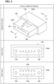
- glass optical fiber 210 itself may be twisted or rotated due to friction between fiber hole 510 and glass optical fiber 210 at a contact point A. That is, as shown in the middle row of FIG. 3 and the lower row of FIG. 3 , when glass optical fiber 210 obliquely enters fiber hole 510, strong friction is generated in a portion of the outer circumferential surface of glass optical fiber 210.
- the oblique entrance of glass optical fiber 210 into fiber hole 510 means that glass optical fiber 210 enters fiber hole 510 from the upper left, the lower left, the upper right, or the lower right when fiber hole 510 is viewed from rear opening 500b.
- glass optical fiber 210 is rotated by the friction received from fiber hole 510. This rotation causes misalignment or rotation of the core position on the ferrule end surface, which leads to deterioration of optical characteristics such as an increase in connection loss.
- friction occurs but rotation does not occur.
- glass optical fiber 210 is rotated.
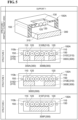
- Optical connector ferrule 100A shown in the upper row of FIG. 4 includes front end surface 100a functioning as a housing, rear opening 100b, a plurality of fiber holes 110, a plurality of fiber introduction holes 120, and a flat surface 310.
- a plurality of opening ends for exposing the end surfaces of the plurality of optical fibers 200A is located on front end surface 100a.
- Rear opening 100b introduces at least an end portion of the plurality of optical fibers 200A into the internal space of optical connector ferrule 100A.
- the plurality of fiber holes 110 has a plurality of opening ends arranged on front end surface 100a, and are each provided in one-to-one correspondence with any of the plurality of optical fibers 200A.
- illustrated fiber hole 110 of the plurality of fiber holes 110 has a diameter that is larger than the outer diameter of corresponding glass optical fiber 210 and less than the outer diameter of the coating of corresponding optical fiber 200A.
- the plurality of fiber introduction holes 120 is each provided between the plurality of fiber holes 110 and the opening end of rear opening 100b in one-to-one correspondence with any of the plurality of fiber holes 110.
- fiber introduction hole 120 shown in the drawing among the plurality of fiber introduction holes 120 has an introduction portion 121 and a taper portion 122.
- Introduction portion 121 has a diameter larger than the outer diameter of the coating of corresponding optical fiber 200A.
- Taper portion 122 communicates with corresponding fiber hole 110 and introduction portion 121.
- first fiber introduction hole 120a and second fiber introduction hole 120b has the same structure as fiber introduction hole 120 of type 1 shown in the upper row of FIG. 4 .
- optical fiber 210 when glass optical fiber 210 after the rotational adjustment is inserted straight into fiber hole 110 along insertion direction S2, the outer circumferential surface of glass optical fiber 210 receives uniform friction from fiber hole 110 regardless of the position, and thus optical fibers 200A do not rotate. As a result, even after optical connector ferrule 100A is attached to the end portion of the plurality of optical fibers 200A, the alignment state of each of the plurality of optical fibers 200A is maintained in a good state. It is noted that, fiber ribbon 200B may be applied instead of the plurality of optical fibers 200A. Further, optical connector ferrule 100B may be applied instead of optical connector ferrule 100A.
- structure 2 shows a three divided structure when optical connector ferrule 100A of type 1 is viewed from rear opening 100b side toward front end surface 100a side as a modification of support 300.
- structure 3 shows a two divided structure when optical connector ferrule 100A of type 1 is viewed from rear opening 100b side toward front end surface 100a side as a modification of support 300.
- structure 4" shows a structure in which gaps are provided at both ends when optical connector ferrule 100A of type 1 is viewed from rear opening 100b side toward front end surface 100a side as a modification of support 300.
- optical connector ferrule 100A shown in the upper row of FIG. 4 is shown.
- the plurality of fiber introduction holes 120 is arranged to face the internal space, and support 300 is provided just below adhesive introduction opening 130.
- Support 300 extends along a first direction from front end surface 100a toward the opening end of rear opening 100b, and also extends along a second direction perpendicular to the first direction. It is noted that, the second direction coincides with the arrangement direction of the plurality of optical fibers 200A.
- the plurality of optical fibers 200A or fiber ribbon 200B is held by flat surface 310 of support 300.
- support 300 may have a structure divided along at least one of the first direction and the second direction, that is, a structure provided with a resin reservoir in which the adhesive injected between the divided supports is retained.
- support 300 is divided into three parts along the second direction: a support 300A having a flat region 310A, a support 300B having a flat region 310B, and a support 300C having a flat region 310C.
- only fiber ribbon 200B is applied, but when support 300 is divided in one-to-one correspondence to the plurality of optical fibers 200A, the support applicable to the plurality of optical fibers 200A.
- support 300 is divided along the second direction, but support 300 may be divided along the first direction.
- the length of flat surface 310 along the first direction is defined by the total length of the flat surfaces of the divided supporting bases.
- a structure such as structure 3 shown in the third row of FIG. 5 or structure 4 shown in the lowermost row of FIG. 5 is also applicable as support 300.
- support 300 is divided into a support 300D having a flat region 310D and a support 300E having a flat region 310E along the second direction.
- support 300 is replaced with a support 300F (a support reduced along the second direction) having a flat region 310F, and resin reservoirs are provided on both sides.
- support 300 may be divided along the first direction.
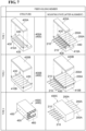
- FIG. 7 is a view for explaining various structures of a fiber holding member applicable to the optical connector ferrule according to the second embodiment of the present disclosure (referred to as “fiber holding member” in FIG. 7 ).
- fiber holding member in each row of FIG. 7 shows, in addition to fiber ribbon 200B shown in the lower row of FIG. 1 , the structure of various fiber holding members 400 (referred to as “structure” in FIG. 7 ) and the mounting state of fiber holding member 400 to the end of the plurality of optical fibers 200A (referred to as “mounting state” in FIG. 7 ).
- the upper row of FIG. 7 (referred to as "type 1" in FIG.
- FIG. 7 shows, as an example of fiber holding member 400, the structure and the mounting state of a fiber holding member 400C of type 3 that holds the portion of glass optical fiber 210 from which the resin coating is removed in the state in which a portion of the resin coating is housed in each of the plurality of optical fibers 200A.
- glass optical fiber 210 of the plurality of optical fibers 200A mounted on lower member 410A is sandwiched between lower member 410A and upper member 420A with the adhesive, and thus fiber holding member 400A is fixed to the exposed regions of glass optical fibers 210 of the plurality of optical fibers 200A from which the coatings are removed.
- Fiber holding member 400B of type 2 shown in the middle row of FIG. 7 is fixed to the coating portions of the plurality of optical fibers 200A, unlike fiber holding member 400A of type 1.
- Fiber holding member 400B is also configured by a lower member 410B for integrally holding the plurality of optical fibers 200A and an upper member 420B serving as a lid.
- Lower member 410B is provided with a plurality of V grooves 430.
- the plurality of optical fibers 200A is mounted on lower member 410B in a state in which the respective coating portions are disposed in V grooves 430.
- fiber holding member 400C of type 3 shown in the lower row of FIG. 7 is a hole array having a through hole 450 for holding the exposed region of glass optical fiber 210 from which the coating is removed in the plurality of optical fibers 200A, and a coating housing portion 460 for housing the coating portion of the plurality of optical fibers 200A.
- Fiber holding member 400C is fixed to the plurality of optical fibers 200A by inserting the end portion of each of the plurality of optical fibers 200A, that is, glass optical fibers 210 from which the coatings are removed, into corresponding through holes 450 from the coating housing portion 460.
- through holes 450 of fiber holding member 400C shown in the lower row of FIG. 7 are provided to hold glass optical fibers 210.
- Each through hole 450 may have a large diameter to hold each coating portion of the plurality of optical fibers 200A.
- FIG. 8 is a diagram for explaining an example of the structure of the optical connector ferrule according to the second embodiment of the present disclosure, an optical fiber mounting operation in the manufacturing process of the optical connector of the present disclosure, and the cross-sectional structure of the optical connector of the present disclosure (referred to as "optical connector ferrule structure 2" in FIG. 8 ).
- An optical connector ferrule 100C according to the second embodiment houses, in the internal space, fiber holding member 400 represented by type 1 to type 3 shown in FIG. 7 in addition to the fiber ribbon 200 shown in the lower row of FIG. 1 .
- the upper row of FIG. 8 (referred to as "type 3" in FIG.
- FIG. 8 shows a cross-sectional view of an example of optical connector ferrule 100C according to the second embodiment, taken along the line II-II in FIG. 2 .
- the middle row of FIG. 8 (referred to as “mounting operation” in FIG. 8 ) shows an operation of mounting optical connector ferrule 100C of type 3 on the ends of the plurality of optical fibers 200A or the ends of fiber ribbon 200B.
- FIG. 8 shows a cross-sectional structure of the optical connector of the present disclosure in which fiber holding member 400 holding the plurality of optical fibers 200A is installed on a flat surface 610 defining the internal space of optical connector ferrule 100C.
- the plurality of fiber holes 110 has a plurality of opening ends disposed on front end surface 100a, and are each provided in one-to-one correspondence to any of the plurality of optical fibers 200A.
- each of the plurality of fiber holes 110 extends along the first direction from front end surface 100a toward the opening end of rear opening 100b.
- the centers of the plurality of opening ends of the plurality of fiber holes 110 are arranged in a row along the second direction perpendicular to the first direction, which is a direction defined on front end surface 100a.
- illustrated fiber hole 110 of the plurality of fiber holes 110 has a diameter that is larger than the outer diameter of corresponding glass optical fiber 210 and less than the outer diameter of the coating of corresponding optical fiber 200A.
- the plurality of fiber introduction holes 120 are each provided between the plurality of fiber holes 110 and the opening end of rear opening 100b in one-to-one correspondence with any of the plurality of fiber holes 110.
- fiber introduction hole 120 shown in the drawing among the plurality of fiber introduction holes 120 has introduction portion 121 and taper portion 122.
- Introduction portion 121 has a diameter larger than the outer diameter of the coating of corresponding optical fiber 200A.
- Taper portion 122 communicates with corresponding fiber hole 110 and introduction portion 121.
- Flat surface 610 is an upper surface of a support 600 constituting a part of optical connector ferrule 100C, and constitutes a part of a surface defining an internal space of optical connector ferrule 100C.
- flat surface 610 is located between the plurality of fiber introduction holes 120 and the opening end of rear opening 100b.
- flat surface 610 directly supports fiber holding member 400 introduced into the ferrule along insertion direction S2 so that the central axes of each of the plurality of optical fibers 200A to which fiber holding member 400 is fixed coincides with the central axes extending along the first direction of each of the plurality of fiber holes 110.
- fiber hole 110, fiber introduction hole 120, and flat surface 610 are portions arranged along the first direction without overlapping each other, as in optical connector ferrule 100A according to the first embodiment.
- a step is provided between fiber introduction hole 120 and flat surface 610.
- the lengths of fiber hole 110, fiber introduction hole 120, and flat surface 610 defined along the first direction satisfy the first to third conditions described above, as in optical connector ferrule 100A according to the first embodiment.
- support 600 having flat surface 610 may be divided along at least one of the first direction and the second direction as shown in FIG. 5 .
- optical connector ferrule 100C is different from the first embodiment in that a structure where the insertion angle of glass optical fiber 210 is defined while fiber holding members 400 are fixed, that is, flat surface 610 of support 600 is provided inside the ferrule.
- a structure where the insertion angle of glass optical fiber 210 is defined while fiber holding members 400 are fixed that is, flat surface 610 of support 600 is provided inside the ferrule.
- glass optical fiber 210 can be inserted straight into fiber hole 110 without entering from an oblique direction.
- the outer circumferential surface of glass optical fiber 210 receives uniform friction from fiber hole 510 regardless of the position, and thus optical fibers 200A do not rotate.
- optical connector ferrule 100C is attached to the end portion of the plurality of optical fibers 200A or fiber ribbon 200B, the alignment state of each of the plurality of optical fibers 200A is maintained in a good state.
- the plurality of optical fibers 200A or fiber ribbon 200B is separated from flat surface 310 in a state where each glass optical fiber 210 located at the end thereof is inserted into corresponding fiber hole 110, as shown in the lower row of FIG. 8 .
- fiber holding member 400 that directly holds the plurality of optical fibers 200A or fiber ribbon 200B directly contacts flat surface 610, and thus the plurality of optical fibers 200A or fiber ribbon 200B is indirectly supported by flat surface 610.
- An optical connector ferrule including a housing that functions as a ferrule configured to be attached to end portions of a plurality of optical fibers each including a glass portion and a coating covering the glass portion, the coatings being partially removed at the end portions, wherein
Landscapes
- Physics & Mathematics (AREA)
- General Physics & Mathematics (AREA)
- Optics & Photonics (AREA)
- Mechanical Coupling Of Light Guides (AREA)
Abstract
Description
- The present disclosure relates to an optical connector ferrule and an optical connector. This application claims priority based on
Japanese Patent Application No. 2022-052129 filed on March 28, 2022 - The MT ferrule, which is a ferrule for a multi-fiber connector integrally attached to the end portions of a plurality of optical fibers, is a resin-molded part having a glass portion from which a coating is removed, that is, a fiber hole having a diameter equal to that of a clad for positioning the clad of each optical fiber, and a fiber introduction hole having a diameter equal to that of the coating for inserting the fiber into the fiber hole with good workability, as a general structure. In recent years, as disclosed in, for example, Non-patent
literature 1, research on the design and performance improvement of such a multi-core connector has been actively conducted. - Non-patent literature 1: Masaki OHMURA, et al. "Multi-Fiber Connectors for Data Center Applications", SEI TECHNICAL REVIEW, NUMBER 86, APRIL, 2018, pp.29-34
- An optical connector ferrule of the present disclosure is configured to be attached to end portions of a plurality of optical fibers each including a glass portion and a coating covering the glass portion, the coatings being partially removed at the end portions. It is noted that, in the glass portion, one or more cores and an impurity doped region such as a refractive index providing member are surrounded by a cladding. The optical connector ferrule of the present disclosure has a front end surface at which a plurality of opening ends configured to allow end surfaces of the plurality of optical fibers to be exposed therethrough are located, a rear opening configured to allow the plurality of optical fibers to be introduced into an internal space of the optical connector ferrule, and a plurality of through holes into each of which a corresponding one of the plurality of optical fibers is to be inserted, the plurality of through holes each extending between a corresponding one of the plurality of opening ends and the internal space along a first direction from the front end surface toward the rear opening.
- Here, the plurality of opening ends is arranged such that centers of the plurality of opening ends forms one or more rows along a second direction perpendicular to the first direction. Each of the plurality of through holes includes a fiber hole with one of the opening ends and a fiber introduction hole allowing communication between the fiber hole and the internal space. The fiber hole has a diameter larger than an outer diameter of the glass portions and smaller than an outer diameter of the coatings. The fiber introduction holes includes an introduction portion having a diameter larger than the outer diameter of each of the coatings and a taper portion allowing communication between the introduction portion and a corresponding one of the fiber holes. The internal space is defined by a plurality of surfaces. At least one flat surface among the plurality of surfaces is configured to support the plurality of optical fibers such that a central axis of each of the plurality of optical fibers coincides with a central axis of a corresponding one of the fiber holes extending in the first direction.
-
-
FIG. 1 is a diagram for explaining the structure of various optical fibers to which optical connector ferrules of the present disclosure are attached. -
FIG. 2 is a diagram for explaining an example of the structure of the optical connector ferrule of the present disclosure. -
FIG. 3 is a diagram for explaining an optical fiber mounting operation in a manufacturing process of a standard optical connector. -
FIG. 4 is a diagram for explaining the various structures of the optical connector ferrule according to the first embodiment of the present disclosure and the optical fiber mounting operation in the manufacturing process of the optical connector of the present disclosure. -
FIG. 5 is a diagram for explaining the various structures of a support including a flat surface provided in the optical connector ferrule according to the first and second embodiments of the present disclosure. -
FIG. 6 is a diagram for explaining still another structure of a support including a flat surface provided in the optical connector ferrule according to the first and second embodiments of the present disclosure. -
FIG. 7 is a diagram for explaining the various structures of the fiber holding member applicable to the optical connector ferrule according to the second embodiment of the present disclosure. -
FIG. 8 is a diagram for explaining an example of the structure of the optical connector ferrule according to the second embodiment of the present disclosure, an optical fiber mounting operation in the manufacturing process of the optical connector of the present disclosure, and the cross-sectional structure of the optical connector of the present disclosure. - The inventors have studied the above-described conventional techniques and have found the following problems. That is, when the glass portion which is the end portion of the optical fiber and from which the coating is removed is inserted into the fiber hole, the optical fiber inserted into the optical connector ferrule body functioning as a housing may be twisted or rotated. Such a change in the installation state at the time of insertion of the optical fiber causes an angular deviation between optical fibers to be optically connected when coincides with the optical connector ferrule is attached to the optical fiber that requires rotational adjustment. This is considered to be caused by the fact that the end portion of the optical fiber is obliquely inserted into the fiber hole when the optical connector ferrule is attached to the optical fiber. As a result, when the optical connector ferrule is attached to the plurality of optical fibers, there is a problem that the installation states of the plurality of optical fibers are different from each other.
- The present disclosure has been made to solve the above-described problems, and aims to provide an optical connector ferrule and optical connector with a structure that makes it possible for a plurality of optical fibers to be inserted into a plurality of fiber holes provided in one-to-one correspondence in a straight manner without causing twisting or rotation.
- According to the optical connector ferrule of the present disclosure, when the optical connector ferrule is mounted on each of the plurality of optical fibers, the end portion of each optical fiber can be straightly inserted into the corresponding fiber hole provided in one-to-one correspondence, and the optical fibers inserted into each of the plurality of fiber holes are effectively suppressed from being twisted and rotated.
- First, the contents of embodiments of the present disclosure will be described by listing them individually.
- (1) An optical connector ferrule of the present disclosure is configured to be attached to end portions of a plurality of optical fibers each including a glass portion and a coating covering the glass portion, the coatings being partially removed at the end portions. It is noted that, in the glass portion, one or more cores and an impurity doped region such as a refractive index providing member are surrounded by a cladding. The optical connector ferrule of the present disclosure has a front end surface at which a plurality of opening ends configured to allow end surfaces of the plurality of optical fibers to be exposed therethrough are located, a rear opening configured to allow the plurality of optical fibers to be introduced into an internal space of the optical connector ferrule, and a plurality of through holes into each of which a corresponding one of the plurality of optical fibers is to be inserted, the plurality of through holes each extending between a corresponding one of the plurality of opening ends and the internal space along a first direction from the front end surface toward the rear opening.
- Here, the plurality of opening ends is arranged so that the centers of the plurality of opening ends constitute one or more rows along the second direction defined on the front end face and perpendicular to the first direction. Each of the plurality of through holes includes a fiber hole with one of the opening ends and a fiber introduction hole connecting between the fiber hole to the internal space. The fiber hole has a diameter larger than an outer diameter of the glass portion and smaller than an outer diameter of the coating. The fiber introduction hole includes an introduction portion having a diameter larger than the outer diameter of each of the coatings and a taper portion connecting the introduction portion to a corresponding one of the fiber holes. The internal space is defined by a plurality of surfaces. At least one flat surface among the plurality of surfaces is configured to support the plurality of optical fibers such that a central axis of each of the plurality of optical fibers coincides with a central axis of a corresponding one of the fiber holes extending in the first direction. In this specification, "coincide" includes both the case where the central axis of the fiber hole and the central axis of the optical fiber completely coincide and the case where they substantially coincide within the range of manufacturing error or the like, and indicates a state where the end surface of the glass portion of the supported optical fiber is accommodated in the fiber introduction hole when the end surface of the glass portion is viewed from the front end surface toward the rear opening.
- According to the optical connector ferrule of the present disclosure, a flat surface for defining an insertion angle of each optical fiber is provided in the optical connector ferrule. Thus, when the optical fibers are mounted, the end portions of the optical fibers can be straightly inserted into the corresponding fiber holes provided in one-to-one correspondence. Further, the optical fibers inserted into each of the plurality of fiber holes are effectively suppressed from being twisted and rotated.
- (2) In the above (1), a length a of each of the fiber holes defined along the first direction, a length b of each of the fiber introduction holes defined along the first direction, and a length c of the flat surface defined along the first direction may satisfy a relationship of a first condition: a<b+c. In order to insert the end portion of each optical fiber straight into the fiber hole, it is necessary for the optical fiber to make contact with the flat surface before insertion. In addition, the end surface of each optical fiber needs to be exposed on the front end surface. Thus, the length of the glass portion of each optical fiber, from which a part of the coating is removed, needs to be equal to or longer than the length a of each fiber hole.
- (3) In the above (1), a length a of each of the fiber holes defined along the first direction and a length c of the flat surface defined along the first direction may satisfy a relationship of a second condition: a<c. The end portion of each optical fiber can be inserted straight into the fiber hole.
- (4) In the above (1), a length b of each of the fiber introduction holes defined along the first direction and a length c of the flat surface defined along the first direction may satisfy a relationship of a third condition: b≤c. In this case as well, the end portion of each optical fiber can be straightly inserted into the fiber hole.
- (5) In any one of (1) to (4), the flat surface may include a plurality of flat regions formed by dividing the flat surface along at least one of the first and second directions. In the case of a support having a flat surface, when the flat surface is formed of a plurality of flat regions, the support is also formed of a plurality of support portions. In such a configuration, the plurality of support portions are disposed with a space interposed therebetween, and the space between the support portions functions as a resin reservoir in which an adhesive (for example, an ultraviolet curable resin) is retained. Thus, it is possible to directly or indirectly firmly support the plurality of optical fibers with respect to the flat surface.
- (6) An optical connector of the present disclosure includes the optical connector ferrule according to any one of (1) to (5), the plurality of optical fibers, and a fiber holding member configured to hold the plurality of optical fibers in a state where the plurality of optical fibers are arranged in one or more rows along the second direction. The fiber holding member is placed on the flat surface while holding the plurality of optical fibers. In particular, the fiber holding member is placed on the flat surface in a state of holding the plurality of optical fibers. In a state in which the fiber holding member is placed on the flat surface, a central axis of a corresponding optical fiber of the plurality of optical fibers substantially coincides with a central axis extending along the first direction of each of the plurality of fiber holes.
- (7) In the above (6), the fiber holding member may constitute a tape fiber including a plurality of optical fibers. Specifically, the fiber holding member may be a resin layer configured to integrally hold the coatings of the plurality of optical fibers and configured to suppress positional deviations between the plurality of optical fibers. In this case, in a state in which the plurality of optical fibers are arranged in one or more rows along the second direction, the end portion of the plurality of optical fibers can be integrally introduced into the internal space of the housing.
- (8) In the above (6), the fiber holding member may have V grooves configured to hold the plurality of optical fibers in a state where the glass portions or the coatings of the plurality of optical fibers are in contact with the V grooves. In this case, as in the case of (7), the end portion of the plurality of optical fibers can be integrally introduced into the internal space of the housing in a state in which the plurality of optical fibers are arranged in one or more rows along the second direction.
- (9) In the above (6), the fiber holding member may include a hole array configured to hold the plurality of optical fibers in a state where the hole array is in contact with the glass portions or the coatings of the plurality of optical fibers. In this case, as in the above (7) and (8), the end portion of the plurality of optical fibers can be integrally introduced into the internal space of the housing in a state in which the plurality of optical fibers are arranged in one or more rows along the second direction.
- (10) In any one of (6) to (9), each of the plurality of optical fibers may be any one of a multi-core optical fiber, a polarization maintaining fiber, and a bundle fiber. Since all of these optical fibers require rotational adjustment, they are suitable for the mounting target of the optical connector ferrule of the present disclosure having a structure that can be inserted straight while suppressing twisting and rotation of the end portion that occur when inserting the optical fiber into the fiber hole.
- Hereinafter, an optical connector ferrule and a specific structure of an optical connector of the present disclosure will be described in detail with reference to the accompanying drawings. It is noted that, the present disclosure is not limited to these examples, but is defined by the scope of the claims, and is intended to include all modifications within the meaning and scope equivalent to the scope of the claims. Further, in the description of the drawings, the same elements are denoted by the same reference numerals, and redundant description thereof will be omitted.
-
FIG. 1 is a diagram for explaining the structure of various optical fibers to which the optical connector ferrules of the present disclosure are attached (referred to as "fiber structure" inFIG. 1 ). It is noted that, the optical connector of the present disclosure is configured by an optical fiber and an optical connector ferrule attached to the end of the optical fiber. The upper row ofFIG. 1 (referred to as "fiber (after alignment)" inFIG. 1 ) shows a plurality ofoptical fibers 200A to which anoptical connector ferrules 100 are attached in a state where the optical fibers are arranged in a row such that the fiber axes are perpendicular to a common predetermined direction. The lower row ofFIG. 1 (referred to as "fiber ribbon (after alignment)" inFIG. 1 ) shows afiber ribbon 200B (including the plurality ofoptical fibers 200A) to whichoptical connector ferrule 100 is attached. - As shown in the upper row of
FIG. 1 , each of the plurality ofoptical fibers 200A is rotationally adjusted along an adjustment direction S1, and thenoptical connector ferrule 100 is mounted.Optical connector ferrule 100 substantially functions as a housing (resin-molded component) that partially houses the end portion of each of the plurality ofoptical fibers 200A. Further, each of the plurality ofoptical fibers 200A includes a glass portion (a glass optical fiber 210) having a cross-sectional structure that requires alignment, and a resin coating that surrounds the outer periphery of glassoptical fiber 210. Examples of the glass optical fiber that requires alignment include a multi-core optical fiber (MCF) and a polarization maintaining optical fiber (PMF). In addition, a bundle fiber BF is applicable to each of the plurality ofoptical fibers 200A. - Here, a multi-core optical fiber MCF includes a plurality of
cores 211 each extending along a central axis AX (fiber axis), amarker 213 used for rotational adjustment, and acommon cladding 212 surroundingcores 211 andmarker 213. A polarization maintaining optical fiber PMF includescore 211 extending so as to include a central axis,stress applying members 214 extending alongcore 211 in a state of being positioned acrosscore 211, andcommon cladding 212 surroundingcore 211 andstress applying members 214. When multi-core optical fiber MCF and polarization maintaining optical fiber PMF are connected to another multi-core optical fiber MCF and another polarization maintaining optical fiber PMF, it is necessary to perform rotational adjustment in advance in order to optically connect the corresponding cores to each other. Bundle fiber BF has a structure in which a plurality of single-coreoptical fibers 251 is bundled, and substantially requires rotational adjustment as in multi-core optical fiber MCF or the like. Each of the plurality of single-coreoptical fibers 251 includes a single-core glassoptical fiber 252 and a coating surrounding single-core glassoptical fiber 252. Specifically, in bundle fiber BF, the end portions of the plurality of single-coreoptical fibers 251 from which the coatings are removed, that is, single-core glassoptical fibers 252 from which the coatings are removed are inserted into astorage container 250. - As described above, a glass optical fiber requiring rotational alignment, such as a multi-core optical fiber MCF, a polarization maintaining optical fiber PMF, or a bundle fiber BF, is applied to each of the glass
optical fibers 210. After the rotational alignment, theoptical connector ferrule 100 is attached to the plurality of tip portions of the plurality ofoptical fibers 200A having the plurality of tip portions from which the coating is removed. - It is noted that, the plurality of
optical fibers 200A, each of which has been rotationally adjusted as described above, may constitutefiber ribbon 200B as shown in the lower row ofFIG. 1 . That is, infiber ribbon 200B, the plurality ofoptical fibers 200A are integrally covered with the resin coating while maintaining the alignment state without changing the relative positions of the plurality ofoptical fibers 200A after the rotational adjustment and before the attachment ofoptical connector ferrule 100. In this way, the resin coating that integrally covers the plurality ofoptical fibers 200A functions as a fiber holding member. -
FIG. 2 is a diagram for explaining an example of the structure of the optical connector ferrule of the present disclosure (referred to as "optical connector ferrule" inFIG. 2 ). The upper row ofFIG. 2 (referred to as "perspective view" inFIG. 2 ) shows an example (perspective view) of the optical connector ferrule of the present disclosure. The middle row ofFIG. 2 (referred to as "front view 1" inFIG. 2 ) shows an example of the front view of the optical connector ferrule of the present disclosure. The lower row ofFIG. 2 (referred to as "front view 2" inFIG. 2 ) shows another example of the front view of the optical connector ferrule of the present disclosure. - As shown in the upper row of
FIG. 2 ,optical connector ferrule 100 of the present disclosure functions as a housing for partially housing the end portion of the plurality ofoptical fibers 200A, that is, glassoptical fiber 210 from which the coating is removed.Optical connector ferrule 100 is a resin-molded component including afront end surface 100a and arear opening 100b. Onfront end surface 100a, opening ends of a plurality offiber holes 110 for positioning an end portion of the plurality ofoptical fibers 200A and opening ends of guide holes 150 for aligningfiber holes 110 ofoptical connector ferrule 100 with fiber holes of another optical connector ferrule are provided. The plurality of fiber holes 110 extends along the first direction perpendicular tofront end surface 100a. It is noted that, the first direction is a direction fromfront end surface 100a to the opening end ofrear opening 100b. Further,optical connector ferrule 100 is provided with an adhesive introduction opening 130 betweenfront end surface 100a andrear opening 100b, into which an adhesive such as an ultraviolet curable adhesive for fixing the plurality ofoptical fibers 200A tooptical connector ferrule 100 is introduced. - It is noted that, the plurality of
fiber holes 110 disposed onfront end surface 100a is arranged in a row along the second direction perpendicular to the first direction, for example, as shown in the middle row ofFIG. 2 . In addition, as shown in the lower row ofFIG. 2 , the plurality of fiber holes 110 may be divided into a plurality offirst fiber holes 110a and a plurality of second fiber holes 110b such that the groups are arranged in parallel along the second direction. The group of the plurality offirst fiber holes 110a and the group of the plurality of second fiber holes 110b are arranged in a row along the second direction. -
FIG. 3 is a diagram for explaining an optical fiber mounting operation in a manufacturing process of a standard optical connector (referred to as "mounting operation (standard optical connector)" inFIG. 3 ). The upper row ofFIG. 3 (referred to as "normal mounting (II-II cross-section)" inFIG. 3 ) shows an operation in which standard anoptical connector ferrule 500 is normally mounted on each end portion of the plurality ofoptical fibers 200A or each end portion offiber ribbon 200B. The middle row ofFIG. 3 (referred to as "abnormal mounting (II-II cross-section)" inFIG. 3 ) shows an operation in which standardoptical connector ferrule 500 is abnormally mounted on each end portion of the plurality ofoptical fibers 200A or each end portion offiber ribbon 200B. The lower row ofFIG. 3 (referred to as "abnormal mounting (I-I cross-section)" inFIG. 3 ) shows an operation in which standardoptical connector ferrule 500 is abnormally mounted on each end portion of the plurality ofoptical fibers 200A or each end portion offiber ribbon 200B. - In the upper row of
FIG. 3 ,optical connector ferrule 500 having a cross-section taken along the line II-II shown in the upper row ofFIG. 2 is shown as a part of a standard optical connector. Further,optical connector ferrule 500 of the standard optical connector includes afront end surface 500a and arear opening 500b.Optical connector ferrule 500 has an opening end onfront end surface 500a, and is provided with a plurality offiber holes 510 extending along the first direction fromfront end surface 500a toward the opening end ofrear opening 500b, a plurality of fiber introduction holes 520 provided in one-to-one correspondence to the plurality of fiber holes 510, and an adhesive introduction opening 530 into which an adhesive such as an ultraviolet curable resin is introduced. Illustratedfiber hole 510 of the plurality of fiber holes 510 has a diameter that is smaller than the coating outer diameter of correspondingoptical fiber 200A and larger than the outer diameter of corresponding glassoptical fiber 210. However, in order to enable accurate positioning ofoptical fiber 200A, the diameter offiber hole 510 may be approximately equal to the outer diameter of corresponding glassoptical fiber 210. In addition,fiber introduction hole 520 shown in the drawing among the plurality of fiber introduction holes 520 has anintroduction portion 521 and ataper portion 522.Introduction portion 521 has a diameter larger than the outer diameter of the coating of correspondingoptical fiber 200A.Taper portion 522 communicates withcorresponding fiber hole 510 andintroduction portion 521. However, in order to enableoptical fiber 200A to be accurately located, the diameter offiber introduction hole 520 may be approximately equal to the coating outer diameter of correspondingoptical fiber 200A. - In the case of the example shown in the upper row of
FIG. 3 , since glassoptical fiber 210 after the rotational adjustment is inserted straight intofiber hole 510 along an insertion direction S2, the friction that the outer circumferential surface of glassoptical fiber 210 receives fromfiber hole 510 is uniform regardless of the location. Thus,optical fiber 200A itself does not rotate. This means that the alignment state ofoptical fiber 200A is maintained well even afteroptical connector ferrule 500 is attached to the end portion ofoptical fiber 200A. - On the other hand, the middle row of
FIG. 3 also shows a cross-sectional view ofoptical connector ferrule 500 constituting a part of the standard optical connector, taken along the line II-II shown in the upper row ofFIG. 2 . The lower row ofFIG. 3 shows a cross-sectional view ofoptical connector ferrule 500 along the line II-II shown in the upper row ofFIG. 2 . Sincefiber hole 510 shown in the drawing among the plurality of fiber holes 510 has a diameter equal to the outer diameter of corresponding glassoptical fiber 210, friction occurs between glassoptical fiber 210 inserted along insertion direction S2 andfiber hole 510. Since it is difficult to perform the rotational adjustment ofoptical fiber 200A after glassoptical fiber 210 is inserted intofiber hole 510 due to the friction, the rotational adjustment ofoptical fiber 200A is generally performed before the insertion. However, depending on the insertion angle of glassoptical fiber 210 with respect tofiber hole 510, glassoptical fiber 210 itself may be twisted or rotated due to friction betweenfiber hole 510 and glassoptical fiber 210 at a contact point A. That is, as shown in the middle row ofFIG. 3 and the lower row ofFIG. 3 , when glassoptical fiber 210 obliquely entersfiber hole 510, strong friction is generated in a portion of the outer circumferential surface of glassoptical fiber 210. Here, the oblique entrance of glassoptical fiber 210 intofiber hole 510 means that glassoptical fiber 210 entersfiber hole 510 from the upper left, the lower left, the upper right, or the lower right whenfiber hole 510 is viewed fromrear opening 500b. In this case, glassoptical fiber 210 is rotated by the friction received fromfiber hole 510. This rotation causes misalignment or rotation of the core position on the ferrule end surface, which leads to deterioration of optical characteristics such as an increase in connection loss. It is noted that, when glassoptical fiber 210 entersfiber hole 510 so as to contact only in the vertical direction or only in the horizontal direction, friction occurs but rotation does not occur. When the axis offiber hole 510 and the entrance axis of glassoptical fiber 210 are shifted in both the vertical direction and the horizontal direction, glassoptical fiber 210 is rotated. -
FIG. 4 is a diagram for explaining various structures of the optical connector ferrule according to the first embodiment of the present disclosure and an optical fiber mounting operation in the manufacturing process of the optical connector of the present disclosure (referred to as "opticalconnector ferrule structure 1" inFIG. 4 ). The upper row ofFIG. 4 (referred to as "type 1" inFIG. 4 ) shows a cross-sectional structure of anoptical connector ferrule 100A as an example of the first embodiment, that is, a cross-section taken along the line II-II shown in the upper row ofFIG. 2 . The middle row ofFIG. 4 (referred to as "type 2" inFIG. 4 ) shows a cross-sectional structure of anoptical connector ferrule 100B as another example of the first embodiment, that is, a cross-section taken along the line II-II shown in the upper row ofFIG. 2 . The lower row ofFIG. 4 (referred to as "mounting operation" inFIG. 4 ) shows an operation of mountingoptical connector ferrule 100A oftype 1 on each end portion of the plurality ofoptical fibers 200A or each end portion offiber ribbon 200B. -
Optical connector ferrule 100A shown in the upper row ofFIG. 4 includesfront end surface 100a functioning as a housing,rear opening 100b, a plurality of fiber holes 110, a plurality of fiber introduction holes 120, and aflat surface 310. A plurality of opening ends for exposing the end surfaces of the plurality ofoptical fibers 200A is located onfront end surface 100a. Rear opening 100b introduces at least an end portion of the plurality ofoptical fibers 200A into the internal space ofoptical connector ferrule 100A. The plurality of fiber holes 110 has a plurality of opening ends arranged onfront end surface 100a, and are each provided in one-to-one correspondence with any of the plurality ofoptical fibers 200A. In addition, each of the plurality of fiber holes 110 extends along the first direction fromfront end surface 100a toward the opening end ofrear opening 100b. In the example shown in the upper row ofFIG. 4 , the centers of the plurality of opening ends of the plurality offiber holes 110 are arranged in a row along the second direction perpendicular to the first direction, which is a direction defined onfront end surface 100a. - Further, illustrated
fiber hole 110 of the plurality of fiber holes 110 has a diameter that is larger than the outer diameter of corresponding glassoptical fiber 210 and less than the outer diameter of the coating of correspondingoptical fiber 200A. The plurality of fiber introduction holes 120 is each provided between the plurality offiber holes 110 and the opening end ofrear opening 100b in one-to-one correspondence with any of the plurality of fiber holes 110. In addition,fiber introduction hole 120 shown in the drawing among the plurality of fiber introduction holes 120 has anintroduction portion 121 and ataper portion 122.Introduction portion 121 has a diameter larger than the outer diameter of the coating of correspondingoptical fiber 200A.Taper portion 122 communicates withcorresponding fiber hole 110 andintroduction portion 121.Flat surface 310 is an upper surface of asupport 300 constituting a part of the housing, and constitutes a part of a surface defining an internal space of the housing. In addition,flat surface 310 is located between the plurality of fiber introduction holes 120 and the opening end ofrear opening 100b. In the example shown in the upper row ofFIG. 4 ,flat surface 310 directly supports the plurality ofoptical fibers 200A orfiber ribbon 200B so that the central axis of each of the plurality ofoptical fibers 200A coincides with the central axis extending along the first direction of each of the plurality of fiber holes 110. That is, in the optical connector obtained through the above-described manufacturing process, the plurality ofoptical fibers 200A orfiber ribbon 200B is in contact withflat surface 310 in a state where each glassoptical fiber 210 located at the end thereof is inserted into correspondingfiber hole 110. - In particular,
fiber hole 110,fiber introduction hole 120, andflat surface 310 are arranged along the first direction without overlapping each other. As shown in the upper row ofFIG. 4 , inoptical connector ferrule 100A corresponding tooptical connector ferrule 100 of the present disclosure, the length a of each of the plurality offiber holes 110 defined along the first direction, the length b of each of the plurality of fiber introduction holes 120 defined along the first direction, and the length c offlat surface 310 defined along the first direction satisfy the relationship of the first condition: a<b+c. In addition, the length a of each of the plurality offiber holes 110 and the length c offlat surface 310 satisfy the relationship of the second condition: a<c. Further, the length b of each of the plurality of fiber introduction holes 120 and the length c offlat surface 310 satisfy the relationship of the third condition: b≤c. - In order to straightly insert the end portion of
optical fiber 200A of the plurality ofoptical fibers 200A into correspondingfiber hole 110,optical fiber 200A andflat surface 310 are in contact with each other before the insertion. In addition, the end surface ofoptical fiber 200A needs to be exposed atfront end surface 100a. Thus, inoptical fiber 200A, the length of glassoptical fiber 210 from which a part of the coating is removed needs to be equal to or longer than the length a ofcorresponding fiber hole 110. When the first condition is not satisfied, that is, whenfiber hole 110 corresponding to glassoptical fiber 210 from which the coating is removed is longer than the sum of the length offiber introduction hole 120 connected tofiber hole 110 and the length offlat surface 310, the coating ofoptical fiber 200A comes into contact withflat surface 310 after glassoptical fiber 210 is inserted intofiber hole 110, and thus the twist and rotation ofoptical fiber 200A cannot be suppressed. In addition, the second condition and the third condition are based on the premise that the insertion angle ofoptical fiber 200A needs to be determined byflat surface 310 at the time when glassoptical fiber 210 ofoptical fiber 200A enters correspondingfiber hole 110. Thus, the length c offlat surface 310 is preferably equal to or longer than the length b offiber introduction hole 120. Further, when the length c offlat surface 310 is less than the length b offiber introduction hole 120, glassoptical fiber 210 inoptical fiber 200A entersfiber hole 110 beforeflat surface 310 andoptical fiber 200A come into contact with each other, and thus the second condition is derived from the first condition and the third condition. - As another example,
optical connector ferrule 100B shown in the middle row ofFIG. 4 functions as a housing in which a group of a plurality offirst fiber holes 110a and a group of a plurality of second fiber holes 110b are arranged onfront end surface 100a as shown in the lower row ofFIG. 2 . The cross-section ofoptical connector ferrule 100B substantially corresponds to the ferrule cross-section taken along the line II-II shown in the upper row ofFIG. 2 . A plurality of firstfiber introduction holes 120a is provided in the plurality offirst fiber holes 110a, andsupport 300 havingflat surface 310 is provided between the plurality of firstfiber introduction holes 120a and the opening end ofrear opening 100b. Similarly, a plurality of secondfiber introduction holes 120b is provided in the plurality ofsecond fiber holes 110b, andsupport 300 havingflat surface 310 is also provided between the plurality of firstfiber introduction holes 120a and the opening end ofrear opening 100b. It is noted that, each of firstfiber introduction hole 120a and secondfiber introduction hole 120b has the same structure asfiber introduction hole 120 oftype 1 shown in the upper row ofFIG. 4 . - As described above,
optical connector ferrule 100A andoptical connector ferrule 100B according to the first embodiment of the present disclosure are both provided with a structure for limiting the insertion angle of glassoptical fiber 210, that is,flat surface 310 ofsupport 300, inside. Thus, for example, when corresponding glassoptical fiber 210 is inserted into any one offiber holes 110 ofoptical connector ferrule 100A, as shown in the lower row ofFIG. 4 , glassoptical fiber 210 can be inserted straight intofiber hole 110 without entering from an oblique direction by insertingoptical fiber 200A into correspondingfiber hole 110 while applying the coating toflat surface 310 along insertion direction S2. As described above, when glassoptical fiber 210 after the rotational adjustment is inserted straight intofiber hole 110 along insertion direction S2, the outer circumferential surface of glassoptical fiber 210 receives uniform friction fromfiber hole 110 regardless of the position, and thusoptical fibers 200A do not rotate. As a result, even afteroptical connector ferrule 100A is attached to the end portion of the plurality ofoptical fibers 200A, the alignment state of each of the plurality ofoptical fibers 200A is maintained in a good state. It is noted that,fiber ribbon 200B may be applied instead of the plurality ofoptical fibers 200A. Further,optical connector ferrule 100B may be applied instead ofoptical connector ferrule 100A. -
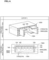
FIG. 5 is a diagram for explaining the various structures of a support including a flat surface provided in the optical connector ferrule according to the first and second embodiments of the present disclosure (referred to as "support 1" inFIG. 5 ). Further,FIG. 6 is a diagram for explaining still another structure of a support including a flat surface provided in the optical connector ferrule according to the first and second embodiments of the present disclosure (referred to as "support 2" inFIG. 6 ). The uppermost row ofFIG. 5 (referred to as "structure 1 (partially cutaway view)" inFIG. 5 ) shows a partially cutaway view ofoptical connector ferrule 100A oftype 1 in a state wheresupport 300 havingflat surface 310 is exposed. The second row ofFIG. 5 (referred to as "structure 2" inFIG. 5 ) shows a three divided structure whenoptical connector ferrule 100A oftype 1 is viewed fromrear opening 100b side towardfront end surface 100a side as a modification ofsupport 300. The third row ofFIG. 5 (referred to as "structure 3" inFIG. 5 ) shows a two divided structure whenoptical connector ferrule 100A oftype 1 is viewed fromrear opening 100b side towardfront end surface 100a side as a modification ofsupport 300. The lowermost row ofFIG. 5 (referred to as "structure 4" inFIG. 5 ) shows a structure in which gaps are provided at both ends whenoptical connector ferrule 100A oftype 1 is viewed fromrear opening 100b side towardfront end surface 100a side as a modification ofsupport 300. Further, in the upper row ofFIG. 6 (referred to as "structure 5 (partially cutaway view)" inFIG. 6 ) shows a partially cutaway view ofoptical connector ferrule 100A oftype 1 in a state where supports 300G provided on the side surface and the upper surface of the ferrule interior are exposed as a modification ofsupport 300. The lower row ofFIG. 6 (referred to as "structure 5 (rear opening side)" inFIG. 6 ) showssupport 300G ofstructure 5 whenoptical connector ferrule 100A oftype 1 is viewed fromrear opening 100b side towardfront end surface 100a. - In the example of
structure 1 shown in the upper row ofFIG. 5 , a partially cutaway view ofoptical connector ferrule 100A shown in the upper row ofFIG. 4 is shown. Inoptical connector ferrule 100A, as described above, the plurality of fiber introduction holes 120 is arranged to face the internal space, andsupport 300 is provided just belowadhesive introduction opening 130.Support 300 extends along a first direction fromfront end surface 100a toward the opening end ofrear opening 100b, and also extends along a second direction perpendicular to the first direction. It is noted that, the second direction coincides with the arrangement direction of the plurality ofoptical fibers 200A. The plurality ofoptical fibers 200A orfiber ribbon 200B is held byflat surface 310 ofsupport 300. - Meanwhile,
support 300 may have a structure divided along at least one of the first direction and the second direction, that is, a structure provided with a resin reservoir in which the adhesive injected between the divided supports is retained. For example, in the example ofstructure 2 shown in the second row ofFIG. 5 ,support 300 is divided into three parts along the second direction: asupport 300A having aflat region 310A, asupport 300B having aflat region 310B, and asupport 300C having aflat region 310C. In this case, onlyfiber ribbon 200B is applied, but whensupport 300 is divided in one-to-one correspondence to the plurality ofoptical fibers 200A, the support applicable to the plurality ofoptical fibers 200A. In the example shown in the second row ofFIG. 5 ,support 300 is divided along the second direction, butsupport 300 may be divided along the first direction. In this case, the length offlat surface 310 along the first direction is defined by the total length of the flat surfaces of the divided supporting bases. - It is noted that, when
fiber ribbon 200B is applied, a structure such asstructure 3 shown in the third row ofFIG. 5 orstructure 4 shown in the lowermost row ofFIG. 5 is also applicable assupport 300. Instructure 3 shown in the third row ofFIG. 5 ,support 300 is divided into asupport 300D having aflat region 310D and asupport 300E having aflat region 310E along the second direction. Instructure 4 shown in the lowermost row ofFIG. 5 ,support 300 is replaced with asupport 300F (a support reduced along the second direction) having aflat region 310F, and resin reservoirs are provided on both sides. In both cases ofstructure 3 andstructure 4,support 300 may be divided along the first direction. - As shown in the upper row and the lower row of
FIG. 6 , the plurality of fiber introduction holes 120 is disposed inoptical connector ferrule 100A to face the internal space, but anadhesive introduction opening 130A is provided at the bottom.Support 300G, which is a modification ofsupport 300, is provided on the side surfaces and the upper surface of the ferrule interior.Support 300G extends along the first direction fromfront end surface 100a toward the opening end ofrear opening 100b, and also extends along the second direction (the arrangement direction of the plurality ofoptical fibers 200A) perpendicular to the first direction. The plurality ofoptical fibers 200A orfiber ribbon 200B is held by aflat region 310G ofsupport 300G. - In the example of structure 5 (
support 300G) shown inFIG. 6 , side portions provided on the side surfaces in the housing and upper portion provided on the upper surface in the housing are integrally formed, but these side portion and upper portion may be formed as a part of the housing, similarly to the supports ofstructure 1 tostructure 4. In addition,support 300G provided in the housing may be provided in the housing only at the side portions or only at the upper portion. Further, support 300G (or either of the side and upper portions) may be combined with the support of any of theabove structure 1 tostructure 4. -
FIG. 7 is a view for explaining various structures of a fiber holding member applicable to the optical connector ferrule according to the second embodiment of the present disclosure (referred to as "fiber holding member" inFIG. 7 ). In each row ofFIG. 7 shows, in addition tofiber ribbon 200B shown in the lower row ofFIG. 1 , the structure of various fiber holding members 400 (referred to as "structure" inFIG. 7 ) and the mounting state offiber holding member 400 to the end of the plurality ofoptical fibers 200A (referred to as "mounting state" inFIG. 7 ). The upper row ofFIG. 7 (referred to as "type 1" inFIG. 7 ) shows, as an example offiber holding member 400, the structure and the mounting state of afiber holding member 400A oftype 1 that holds the portion of glassoptical fiber 210 from which the resin coating is removed in each of the plurality ofoptical fibers 200A. In the middle row ofFIG. 7 (referred to as "type 2" inFIG. 7 ) shows, as an example offiber holding member 400, the structure and the mounting state of afiber holding member 400B oftype 2 that holds the resin coating portion of each of the plurality ofoptical fibers 200A. The lower row ofFIG. 7 (referred to as "type 3" inFIG. 7 ) shows, as an example offiber holding member 400, the structure and the mounting state of afiber holding member 400C oftype 3 that holds the portion of glassoptical fiber 210 from which the resin coating is removed in the state in which a portion of the resin coating is housed in each of the plurality ofoptical fibers 200A. -
Fiber holding member 400A oftype 1 shown in the upper row ofFIG. 7 is configured by alower member 410A for integrally holding the plurality ofoptical fibers 200A, and anupper member 420A serving as a lid.Lower member 410A includes a plurality ofV grooves 430 andlower member 410A having a holdingportion 440 in which coating portions of the plurality ofoptical fibers 200A are disposed. The plurality ofoptical fibers 200A is mounted onlower member 410A in a state in which the respective coating portions are disposed in holdingportion 440 and in a state in which the respective end portions (glassoptical fibers 210 from which the coating is removed) are disposed inV grooves 430. Further, glassoptical fiber 210 of the plurality ofoptical fibers 200A mounted onlower member 410A is sandwiched betweenlower member 410A andupper member 420A with the adhesive, and thusfiber holding member 400A is fixed to the exposed regions of glassoptical fibers 210 of the plurality ofoptical fibers 200A from which the coatings are removed. -
Fiber holding member 400B oftype 2 shown in the middle row ofFIG. 7 is fixed to the coating portions of the plurality ofoptical fibers 200A, unlikefiber holding member 400A oftype 1.Fiber holding member 400B is also configured by alower member 410B for integrally holding the plurality ofoptical fibers 200A and anupper member 420B serving as a lid.Lower member 410B is provided with a plurality ofV grooves 430. The plurality ofoptical fibers 200A is mounted onlower member 410B in a state in which the respective coating portions are disposed inV grooves 430. Further, the coating portions of the plurality ofoptical fibers 200A mounted onlower member 410B is sandwiched betweenlower member 410B andupper member 420B via an adhesive, wherebyfiber holding member 400A is fixed to the coating portions of the plurality ofoptical fibers 200A. - Further,
fiber holding member 400C oftype 3 shown in the lower row ofFIG. 7 is a hole array having a throughhole 450 for holding the exposed region of glassoptical fiber 210 from which the coating is removed in the plurality ofoptical fibers 200A, and acoating housing portion 460 for housing the coating portion of the plurality ofoptical fibers 200A.Fiber holding member 400C is fixed to the plurality ofoptical fibers 200A by inserting the end portion of each of the plurality ofoptical fibers 200A, that is, glassoptical fibers 210 from which the coatings are removed, into corresponding throughholes 450 from thecoating housing portion 460. Although throughholes 450 offiber holding member 400C shown in the lower row ofFIG. 7 are provided to hold glassoptical fibers 210. Each throughhole 450 may have a large diameter to hold each coating portion of the plurality ofoptical fibers 200A. -
FIG. 8 is a diagram for explaining an example of the structure of the optical connector ferrule according to the second embodiment of the present disclosure, an optical fiber mounting operation in the manufacturing process of the optical connector of the present disclosure, and the cross-sectional structure of the optical connector of the present disclosure (referred to as "opticalconnector ferrule structure 2" inFIG. 8 ). Anoptical connector ferrule 100C according to the second embodiment houses, in the internal space,fiber holding member 400 represented bytype 1 to type 3 shown inFIG. 7 in addition to the fiber ribbon 200 shown in the lower row ofFIG. 1 . The upper row ofFIG. 8 (referred to as "type 3" inFIG. 8 ) shows a cross-sectional view of an example ofoptical connector ferrule 100C according to the second embodiment, taken along the line II-II inFIG. 2 . The middle row ofFIG. 8 (referred to as "mounting operation" inFIG. 8 ) shows an operation of mountingoptical connector ferrule 100C oftype 3 on the ends of the plurality ofoptical fibers 200A or the ends offiber ribbon 200B. In the lower row ofFIG. 8 (referred to as "after mounting" inFIG. 8 ), a cross-sectional structure of the optical connector of the present disclosure is shown in whichfiber holding member 400 holding the plurality ofoptical fibers 200A is installed on aflat surface 610 defining the internal space ofoptical connector ferrule 100C. -
Optical connector ferrule 100C shown in the upper row ofFIG. 8 functions as a housing for housing the end portions of the plurality ofoptical fibers 200A, similarly tooptical connector ferrule 100A shown in the upper row ofFIG. 4 . However,optical connector ferrule 100C is different fromoptical connector ferrule 100A in that it has a structure for housingfiber holding members 400 with various structures shown inFIG. 7 . That is,optical connector ferrule 100C includesfront end surface 100a,rear opening 100b, a plurality of fiber holes 110, a plurality of fiber introduction holes 120, andflat surface 610. A plurality of opening ends for exposing the end surfaces of the plurality ofoptical fibers 200A is located onfront end surface 100a. As shown in the middle row ofFIG. 8 , at least the end portions of the plurality ofoptical fibers 200A to whichfiber holding member 400 is fixed are introduced into the internal space ofoptical connector ferrule 100C fromrear opening 100b along the insertion direction S2. In this case,fiber holding member 400 is disposed onflat surface 610. The plurality of fiber holes 110 has a plurality of opening ends disposed onfront end surface 100a, and are each provided in one-to-one correspondence to any of the plurality ofoptical fibers 200A. In addition, each of the plurality of fiber holes 110 extends along the first direction fromfront end surface 100a toward the opening end ofrear opening 100b. In the example shown in the upper row ofFIG. 8 , the centers of the plurality of opening ends of the plurality offiber holes 110 are arranged in a row along the second direction perpendicular to the first direction, which is a direction defined onfront end surface 100a. - Further, illustrated
fiber hole 110 of the plurality of fiber holes 110 has a diameter that is larger than the outer diameter of corresponding glassoptical fiber 210 and less than the outer diameter of the coating of correspondingoptical fiber 200A. The plurality of fiber introduction holes 120 are each provided between the plurality offiber holes 110 and the opening end ofrear opening 100b in one-to-one correspondence with any of the plurality of fiber holes 110. In addition,fiber introduction hole 120 shown in the drawing among the plurality of fiber introduction holes 120 hasintroduction portion 121 andtaper portion 122.Introduction portion 121 has a diameter larger than the outer diameter of the coating of correspondingoptical fiber 200A.Taper portion 122 communicates withcorresponding fiber hole 110 andintroduction portion 121.Flat surface 610 is an upper surface of asupport 600 constituting a part ofoptical connector ferrule 100C, and constitutes a part of a surface defining an internal space ofoptical connector ferrule 100C. In addition,flat surface 610 is located between the plurality of fiber introduction holes 120 and the opening end ofrear opening 100b. In the example shown in the middle row ofFIG. 8 ,flat surface 610 directly supportsfiber holding member 400 introduced into the ferrule along insertion direction S2 so that the central axes of each of the plurality ofoptical fibers 200A to whichfiber holding member 400 is fixed coincides with the central axes extending along the first direction of each of the plurality of fiber holes 110. - It is noted that,
fiber hole 110,fiber introduction hole 120, andflat surface 610 are portions arranged along the first direction without overlapping each other, as inoptical connector ferrule 100A according to the first embodiment. However, inoptical connector ferrule 100C according to the second embodiment, a step is provided betweenfiber introduction hole 120 andflat surface 610. The lengths offiber hole 110,fiber introduction hole 120, andflat surface 610 defined along the first direction satisfy the first to third conditions described above, as inoptical connector ferrule 100A according to the first embodiment. Further,support 600 havingflat surface 610 may be divided along at least one of the first direction and the second direction as shown inFIG. 5 . - As described above,
optical connector ferrule 100C according to the second embodiment of the present disclosure is different from the first embodiment in that a structure where the insertion angle of glassoptical fiber 210 is defined whilefiber holding members 400 are fixed, that is,flat surface 610 ofsupport 600 is provided inside the ferrule. Thus, for example, as shown in the middle row ofFIG. 8 , when glass optical fibers 210 (the end portions ofoptical fibers 200A to whichfiber holding member 400 is fixed) corresponding tofiber holes 110 ofoptical connector ferrule 100C is inserted,optical fibers 200A are inserted into corresponding fiber holes 110 while the bottom surface offiber holding member 400 abuts onflat surface 610 along insertion direction S2. Thus, glassoptical fiber 210 can be inserted straight intofiber hole 110 without entering from an oblique direction. As described above, when glassoptical fiber 210 after the rotational adjustment is inserted straight intofiber hole 510 along insertion direction S2, the outer circumferential surface of glassoptical fiber 210 receives uniform friction fromfiber hole 510 regardless of the position, and thusoptical fibers 200A do not rotate. As a result, even afteroptical connector ferrule 100C is attached to the end portion of the plurality ofoptical fibers 200A orfiber ribbon 200B, the alignment state of each of the plurality ofoptical fibers 200A is maintained in a good state. - In the optical connector obtained through the above-described manufacturing process, the plurality of
optical fibers 200A orfiber ribbon 200B is separated fromflat surface 310 in a state where each glassoptical fiber 210 located at the end thereof is inserted into correspondingfiber hole 110, as shown in the lower row ofFIG. 8 . However,fiber holding member 400 that directly holds the plurality ofoptical fibers 200A orfiber ribbon 200B directly contactsflat surface 610, and thus the plurality ofoptical fibers 200A orfiber ribbon 200B is indirectly supported byflat surface 610. - As can be understood from the description of the embodiments and modifications described above, the present specification also includes the disclosure of the following aspects.
- An optical connector ferrule including a housing that functions as a ferrule configured to be attached to end portions of a plurality of optical fibers each including a glass portion and a coating covering the glass portion, the coatings being partially removed at the end portions, wherein
- the housing has
- a front end surface at which a plurality of opening ends configured to allow end surfaces of the plurality of optical fibers to be exposed therethrough are located,
- a rear opening configured to allow at least the end portions of the plurality of optical fibers to be introduced into an internal space of the housing, and
- a plurality of fiber holes formed to have the plurality of opening ends and to correspond in one-to-one to the plurality of optical fibers, the plurality of fiber holes each extending along a first direction from the front end surface toward an opening end of the rear opening, being arranged such that centers of the plurality of opening ends form one or more rows along a second direction that is defined on the front end surface and that is perpendicular to the first direction, and each being defined by an inner wall surface having a diameter larger than an outer diameter of each of the glass portions and smaller than an outer diameter of each of the coatings,
- a plurality of fiber introduction holes formed between the plurality of fiber holes and the opening end of the rear opening and corresponding in one-to-one to the plurality of fiber holes, each of the plurality of fiber introduction holes including an introduction portion defined by an inner wall surface having a diameter larger than the outer diameter of each of the coatings and a taper portion allowing communication between the introduction portion and a corresponding one of the plurality of fiber holes, and
- a flat surface forming a portion of a surface defining the internal space of the housing, the flat surface being located between the plurality of fiber introduction holes and the opening end of the rear opening and being configured to directly or indirectly support the plurality of optical fibers such that a central axis of each of the plurality of optical fibers substantially coincides with a central axis of a corresponding one of the fiber holes extending in the first direction.
-
- 100, 100A, 100B, 100C optical connector ferrule
- 100a front end surface
- 100b rear opening
- 110 fiber hole
- 110a first fiber hole
- 110b second fiber hole
- 120 fiber introduction hole
- 120a first fiber introduction hole
- 120b second fiber introduction hole
- 121 introduction portion
- 122 taper portion
- 130, 130A adhesive introduction opening
- 150 guide hole
- 200A optical fiber
- 200B fiber ribbon
- 210 glass optical fiber
- 211 core
- 212 common cladding
- 213 marker
- 214 stress applying member
- 250 storage container
- 251 single-core optical fiber
- 252 single-core glass optical fiber
- 300, 300A, 300B, 300C, 300D, 300E, 300F, 300G support
- 310 flat surface
- 310A, 310B, 310C, 310D, 310E, 310F, 310G flat region
- 400, 400A, 400B, 400C fiber holding member
- 410A, 410B lower member
- 420A, 420B upper member
- 430 V groove
- 440 holding portion
- 450 through hole
- 460 coating housing portion
- 500 optical connector ferrule
- 500a front end surface
- 500b rear opening
- 510 fiber hole
- 520 fiber introduction hole
- 521 introduction portion
- 522 taper portion
- 530 adhesive introduction opening
- 600 support
- 610 flat surface
- S1 adjustment direction
- S2 insertion direction
- A contact point
- MCF multi-core optical fiber
- PMF polarization maintaining optical fiber
- BF bundle fiber
Claims (10)
- An optical connector ferrule configured to be attached to end portions of a plurality of optical fibers each including a glass portion and a coating covering the glass portion, the coatings being partially removed at the end portions,wherein the optical connector ferrule hasa front end surface at which a plurality of opening ends configured to allow end surfaces of the plurality of optical fibers to be exposed therethrough are located,a rear opening configured to allow the plurality of optical fibers to be introduced into an internal space of the optical connector ferrule, anda plurality of through holes into each of which a corresponding one of the plurality of optical fibers is to be inserted, the plurality of through holes each extending between a corresponding one of the plurality of opening ends and the internal space along a first direction from the front end surface toward the rear opening,wherein the plurality of opening ends is arranged such that centers of the plurality of opening ends form one or a plurality of rows along a second direction perpendicular to the first direction,wherein each of the plurality of through holes includes a fiber hole with one of the opening ends and a fiber introduction hole allowing communication between the fiber hole and the internal space,wherein each of the fiber holes has a diameter larger than an outer diameter of each of the glass portions and smaller than an outer diameter of each of the coatings,wherein each of the fiber introduction holes includes an introduction portion having a diameter larger than the outer diameter of each of the coatings and a taper portion allowing communication between the introduction portion and a corresponding one of the fiber holes,wherein the internal space is defined by a plurality of surfaces, andwherein at least one flat surface among the plurality of surfaces is configured to support the plurality of optical fibers such that a central axis of each of the plurality of optical fibers coincides with a central axis of a corresponding one of the fiber holes extending in the first direction.
- The optical connector ferrule according to claim 1,
wherein a length a of each of the fiber holes defined along the first direction, a length b of each of the fiber introduction holes defined along the first direction, and a length c of the flat surface defined along the first direction satisfy a relationship below.
- The optical connector ferrule according to claim 1,
wherein a length a of each of the fiber holes defined along the first direction and a length c of the flat surface defined along the first direction satisfy a relationship below.
- The optical connector ferrule according to claim 1,
wherein a length b of each of the fiber introduction holes defined along the first direction and a length c of the flat surface defined along the first direction satisfy a relationship below.
- The optical connector ferrule according to any one of claim 1 to claim 4,
wherein the flat surface includes a plurality of flat regions formed by dividing the flat surface along at least one of the first and second directions. - An optical connector comprising:the optical connector ferrule according to any one of claim 1 to claim 5;the plurality of optical fibers; anda fiber holding member configured to hold the plurality of optical fibers in a state where the plurality of optical fibers are arranged in one or more rows along the second direction,wherein the fiber holding member is placed on the flat surface while holding the plurality of optical fibers.
- The optical connector according to claim 6,
wherein the fiber holding member is a resin layer configured to integrally hold the coatings of the plurality of optical fibers and configured to suppress positional deviations between the plurality of optical fibers. - The optical connector according to claim 6,
wherein the fiber holding member has V grooves configured to hold the plurality of optical fibers in a state where the glass portions or the coatings of the plurality of optical fibers are in contact with the V grooves. - The optical connector according to claim 6,
wherein the fiber holding member includes a hole array configured to hold the plurality of optical fibers in a state where the hole array is in contact with the glass portions or the coatings of the plurality of optical fibers. - The optical connector according to any one of claim 6 to claim 9,
wherein each of the plurality of optical fibers is any one of a multi-core optical fiber, a polarization maintaining fiber, and a bundle fiber.
Applications Claiming Priority (2)
| Application Number | Priority Date | Filing Date | Title |
|---|---|---|---|
| JP2022052129 | 2022-03-28 | ||
| PCT/JP2023/005809 WO2023188976A1 (en) | 2022-03-28 | 2023-02-17 | Optical connector ferrule and optical connector |
Publications (2)
| Publication Number | Publication Date |
|---|---|
| EP4502687A1 true EP4502687A1 (en) | 2025-02-05 |
| EP4502687A4 EP4502687A4 (en) | 2025-07-02 |
Family
ID=88200394
Family Applications (1)
| Application Number | Title | Priority Date | Filing Date |
|---|---|---|---|
| EP23779006.8A Pending EP4502687A4 (en) | 2022-03-28 | 2023-02-17 | FERRULE FOR AN OPTICAL CONNECTOR AND OPTICAL CONNECTOR |
Country Status (5)
| Country | Link |
|---|---|
| US (1) | US20250138252A1 (en) |
| EP (1) | EP4502687A4 (en) |
| JP (1) | JPWO2023188976A1 (en) |
| CN (1) | CN118679412A (en) |
| WO (1) | WO2023188976A1 (en) |
Family Cites Families (12)
| Publication number | Priority date | Publication date | Assignee | Title |
|---|---|---|---|---|
| JPH1172644A (en) * | 1997-08-28 | 1999-03-16 | Sumitomo Electric Ind Ltd | Optical fiber array, ferrule, and optical connector using this ferrule |
| JP3479964B2 (en) * | 1998-09-22 | 2003-12-15 | 住友電気工業株式会社 | Optical connector assembly method |
| US6264375B1 (en) * | 1999-10-05 | 2001-07-24 | Sumitomo Electric Industries, Ltd. | Fiber optic connector ferrule and method of making the same |
| JP2004045751A (en) * | 2002-07-11 | 2004-02-12 | Sumitomo Electric Ind Ltd | Multi-core optical connector |
| JP4711301B2 (en) * | 2006-01-20 | 2011-06-29 | 株式会社フジクラ | Optical connector |
| US9069143B2 (en) * | 2010-03-16 | 2015-06-30 | Ofs Fitel, Llc | Multifiber connectors for multicore optical fiber cables |
| JP6157457B2 (en) * | 2012-05-14 | 2017-07-05 | 古河電気工業株式会社 | Multi-fiber optical connector |
| JP2019066634A (en) * | 2017-09-29 | 2019-04-25 | 住友電気工業株式会社 | Boots, ferrules and optical connectors |
| WO2021020073A1 (en) * | 2019-08-01 | 2021-02-04 | 株式会社フジクラ | Optical connector |
| JP2021026217A (en) * | 2019-08-01 | 2021-02-22 | 株式会社フジクラ | Optical connector |
| US12416769B2 (en) * | 2020-03-16 | 2025-09-16 | Sumitomo Electric Industries, Ltd. | Optical fiber connection component and method for manufacturing optical fiber connection component |
| JP7140166B2 (en) | 2020-09-23 | 2022-09-21 | カシオ計算機株式会社 | PRINTING DEVICE, PRINTING METHOD, AND PROGRAM |
-
2023
- 2023-02-17 CN CN202380021387.6A patent/CN118679412A/en active Pending
- 2023-02-17 EP EP23779006.8A patent/EP4502687A4/en active Pending
- 2023-02-17 JP JP2024511426A patent/JPWO2023188976A1/ja active Pending
- 2023-02-17 WO PCT/JP2023/005809 patent/WO2023188976A1/en not_active Ceased
- 2023-02-17 US US18/836,878 patent/US20250138252A1/en active Pending
Also Published As
| Publication number | Publication date |
|---|---|
| CN118679412A (en) | 2024-09-20 |
| JPWO2023188976A1 (en) | 2023-10-05 |
| EP4502687A4 (en) | 2025-07-02 |
| WO2023188976A1 (en) | 2023-10-05 |
| US20250138252A1 (en) | 2025-05-01 |
Similar Documents
| Publication | Publication Date | Title |
|---|---|---|
| US11822134B2 (en) | Optical-fiber holding component, optical connector, and optical coupling structure | |
| US10451830B2 (en) | Fiber optic cable assembly and fabrication method using sequentially arranged boots for multi-fiber ferrule | |
| EP3807684B1 (en) | High-density optical fiber ribbon and ribbon cable interconnects employing small diameter optical fibers | |
| US9366829B2 (en) | Multi-ferrule connector for multicore fiber terminations | |
| EP3734339A1 (en) | Optical connector and optical connection structure | |
| JP2020052133A (en) | Ferrule, sleeve, and ferrule member manufacturing method for optical connector | |
| EP4502687A1 (en) | Optical connector ferrule and optical connector | |
| WO2023199632A1 (en) | Optical fiber holding component, optical fiber coupling structure, optical connector, and optical coupling structure | |
| CN113330343B (en) | Ferrule and optical connector | |
| US12248172B2 (en) | Method of manufacturing optical connector | |
| TWI890959B (en) | Multi-core optical sleeve, multi-core optical connector and manufacturing method of multi-core optical sleeve | |
| EP4266097B1 (en) | Optical connector and optical connection structure | |
| JPWO2023188976A5 (en) | ||
| EP4418028A1 (en) | Optical connector | |
| EP4647820A1 (en) | Optical connector ferrule, optical connector, and optical coupling structure | |
| US20230251433A1 (en) | Fiber positioning arrangement for optical fibers | |
| WO2025239152A1 (en) | Optical connector | |
| US12124090B2 (en) | Optical cable assemblies having filler optical fibers and methods of fabricating the same | |
| WO2024029270A1 (en) | Optical connector, ferrule, and optical coupling structure | |
| WO2024252931A1 (en) | Optical fiber holding component, optical fiber assembly, optical connector, and optical coupling device | |
| EP4733821A1 (en) | Optical fiber holding component, optical fiber coupling structure, optical connector, optical coupling structure, and method for manufacturing optical fiber coupling structure | |
| EP4270070A1 (en) | Optical fiber ribbon, optical fiber connection component, and method for manufacturing optical fiber connection component | |
| WO2025075062A1 (en) | Optical connector, optical connection assembly, and method for manufacturing optical connector | |
| WO2025075063A1 (en) | Optical connector, optical connection assembly, optical waveguide member, and method for manufacturing optical connector | |
| CN121399515A (en) | Holding member, optical connector, and optical connection assembly |
Legal Events
| Date | Code | Title | Description |
|---|---|---|---|
| STAA | Information on the status of an ep patent application or granted ep patent |
Free format text: STATUS: THE INTERNATIONAL PUBLICATION HAS BEEN MADE |
|
| PUAI | Public reference made under article 153(3) epc to a published international application that has entered the european phase |
Free format text: ORIGINAL CODE: 0009012 |
|
| STAA | Information on the status of an ep patent application or granted ep patent |
Free format text: STATUS: REQUEST FOR EXAMINATION WAS MADE |
|
| 17P | Request for examination filed |
Effective date: 20240904 |
|
| AK | Designated contracting states |
Kind code of ref document: A1 Designated state(s): AL AT BE BG CH CY CZ DE DK EE ES FI FR GB GR HR HU IE IS IT LI LT LU LV MC ME MK MT NL NO PL PT RO RS SE SI SK SM TR |
|
| A4 | Supplementary search report drawn up and despatched |
Effective date: 20250604 |
|
| DAV | Request for validation of the european patent (deleted) | ||
| DAX | Request for extension of the european patent (deleted) | ||
| RIC1 | Information provided on ipc code assigned before grant |
Ipc: G02B 6/36 20060101AFI20250528BHEP |