EP4502624A1 - Spring connector - Google Patents
Spring connector Download PDFInfo
- Publication number
- EP4502624A1 EP4502624A1 EP23774505.4A EP23774505A EP4502624A1 EP 4502624 A1 EP4502624 A1 EP 4502624A1 EP 23774505 A EP23774505 A EP 23774505A EP 4502624 A1 EP4502624 A1 EP 4502624A1
- Authority
- EP
- European Patent Office
- Prior art keywords
- wound portion
- pin
- tube
- central axis
- roughly
- Prior art date
- Legal status (The legal status is an assumption and is not a legal conclusion. Google has not performed a legal analysis and makes no representation as to the accuracy of the status listed.)
- Pending
Links
Images


Classifications
-
- H—ELECTRICITY
- H01—ELECTRIC ELEMENTS
- H01R—ELECTRICALLY-CONDUCTIVE CONNECTIONS; STRUCTURAL ASSOCIATIONS OF A PLURALITY OF MUTUALLY-INSULATED ELECTRICAL CONNECTING ELEMENTS; COUPLING DEVICES; CURRENT COLLECTORS
- H01R13/00—Details of coupling devices of the kinds covered by groups H01R12/70 or H01R24/00 - H01R33/00
- H01R13/02—Contact members
- H01R13/22—Contacts for co-operating by abutting
- H01R13/24—Contacts for co-operating by abutting resilient; resiliently-mounted
- H01R13/2407—Contacts for co-operating by abutting resilient; resiliently-mounted characterized by the resilient means
- H01R13/2421—Contacts for co-operating by abutting resilient; resiliently-mounted characterized by the resilient means using coil springs
-
- F—MECHANICAL ENGINEERING; LIGHTING; HEATING; WEAPONS; BLASTING
- F16—ENGINEERING ELEMENTS AND UNITS; GENERAL MEASURES FOR PRODUCING AND MAINTAINING EFFECTIVE FUNCTIONING OF MACHINES OR INSTALLATIONS; THERMAL INSULATION IN GENERAL
- F16F—SPRINGS; SHOCK-ABSORBERS; MEANS FOR DAMPING VIBRATION
- F16F1/00—Springs
- F16F1/02—Springs made of steel or other material having low internal friction; Wound, torsion, leaf, cup, ring or the like springs, the material of the spring not being relevant
- F16F1/04—Wound springs
- F16F1/046—Wound springs with partial nesting of inner and outer coils
-
- F—MECHANICAL ENGINEERING; LIGHTING; HEATING; WEAPONS; BLASTING
- F16—ENGINEERING ELEMENTS AND UNITS; GENERAL MEASURES FOR PRODUCING AND MAINTAINING EFFECTIVE FUNCTIONING OF MACHINES OR INSTALLATIONS; THERMAL INSULATION IN GENERAL
- F16F—SPRINGS; SHOCK-ABSORBERS; MEANS FOR DAMPING VIBRATION
- F16F1/00—Springs
- F16F1/02—Springs made of steel or other material having low internal friction; Wound, torsion, leaf, cup, ring or the like springs, the material of the spring not being relevant
- F16F1/04—Wound springs
- F16F1/047—Wound springs characterised by varying pitch
-
- G—PHYSICS
- G01—MEASURING; TESTING
- G01R—MEASURING ELECTRIC VARIABLES; MEASURING MAGNETIC VARIABLES
- G01R1/00—Details of instruments or arrangements of the types included in groups G01R5/00 - G01R13/00 and G01R31/00
- G01R1/02—General constructional details
- G01R1/06—Measuring leads; Measuring probes
- G01R1/067—Measuring probes
- G01R1/06711—Probe needles; Cantilever beams; "Bump" contacts; Replaceable probe pins
- G01R1/06716—Elastic
- G01R1/06722—Spring-loaded
-
- F—MECHANICAL ENGINEERING; LIGHTING; HEATING; WEAPONS; BLASTING
- F16—ENGINEERING ELEMENTS AND UNITS; GENERAL MEASURES FOR PRODUCING AND MAINTAINING EFFECTIVE FUNCTIONING OF MACHINES OR INSTALLATIONS; THERMAL INSULATION IN GENERAL
- F16F—SPRINGS; SHOCK-ABSORBERS; MEANS FOR DAMPING VIBRATION
- F16F2230/00—Purpose; Design features
- F16F2230/38—Off-centre positioning
-
- G—PHYSICS
- G01—MEASURING; TESTING
- G01R—MEASURING ELECTRIC VARIABLES; MEASURING MAGNETIC VARIABLES
- G01R1/00—Details of instruments or arrangements of the types included in groups G01R5/00 - G01R13/00 and G01R31/00
- G01R1/02—General constructional details
- G01R1/06—Measuring leads; Measuring probes
- G01R1/067—Measuring probes
- G01R1/073—Multiple probes
- G01R1/07307—Multiple probes with individual probe elements, e.g. needles, cantilever beams or bump contacts, fixed in relation to each other, e.g. bed of nails fixture or probe card
- G01R1/07314—Multiple probes with individual probe elements, e.g. needles, cantilever beams or bump contacts, fixed in relation to each other, e.g. bed of nails fixture or probe card the body of the probe being perpendicular to test object, e.g. bed of nails or probe with bump contacts on a rigid support
-
- H—ELECTRICITY
- H01—ELECTRIC ELEMENTS
- H01R—ELECTRICALLY-CONDUCTIVE CONNECTIONS; STRUCTURAL ASSOCIATIONS OF A PLURALITY OF MUTUALLY-INSULATED ELECTRICAL CONNECTING ELEMENTS; COUPLING DEVICES; CURRENT COLLECTORS
- H01R12/00—Structural associations of a plurality of mutually-insulated electrical connecting elements, specially adapted for printed circuits, e.g. printed circuit boards [PCB], flat or ribbon cables, or like generally planar structures, e.g. terminal strips, terminal blocks; Coupling devices specially adapted for printed circuits, flat or ribbon cables, or like generally planar structures; Terminals specially adapted for contact with, or insertion into, printed circuits, flat or ribbon cables, or like generally planar structures
- H01R12/70—Coupling devices
- H01R12/71—Coupling devices for rigid printing circuits or like structures
- H01R12/72—Coupling devices for rigid printing circuits or like structures coupling with the edge of the rigid printed circuits or like structures
- H01R12/73—Coupling devices for rigid printing circuits or like structures coupling with the edge of the rigid printed circuits or like structures connecting to other rigid printed circuits or like structures
Definitions
- the present invention relates to a spring connector used in a portion in which electrical connection is detachably performed in various electronic devices.
- a spring connector in general, includes a pin, a tube that holds the pin in a slidable manner, and a spring that is accommodated in the tube and biases a distal end portion of the pin in a direction in which the pin protrudes from inside of the tube.
- a spring connector in which a portion (hereinafter, referred to as a pin bottom surface) of a pin that comes into contact with a spring is processed into a conical shape.
- a spring is installed in a space formed by the pin and a hole of a tube, and as shown in FIG. 1A and FIG. 1B , a spring 60 includes a central portion that has a substantially equal diameter and a tapered portion that is adjacent to the central portion, has a gradually reduced diameter, and has a central axis offset in an oblique direction from the central axis of the central portion.
- the central axis of the tapered portion intersects the central axis of the central portion.
- Patent Literature 1 Japanese Patent No. 5197754
- An example of an object of the present invention is to provide a spring connector capable of stabilizing a lateral pressure for pressing a pin against an inner wall of a tube.
- An aspect of the present invention includes: a conductive tube; a conductive pin that is slidable in the tube; and a spring that is provided in the tube and biases the pin in a direction in which the pin protrudes from the tube, in which the spring includes a roughly wound portion and a densely wound portion positioned on an end portion side of the roughly wound portion and engaged with the pin, and a diameter of the densely wound portion is smaller than a diameter of the roughly wound portion, and a central axis of the densely wound portion and a central axis of the roughly wound portion are different from each other.
- the pin may include a protruding portion protruding outside of the tube and an inlet pipe portion positioned in the tube, and the inlet pipe portion may include a sliding portion that is slidable with respect to an inner wall of the tube and a conical portion engaged with the densely wound portion of the spring.
- a boundary portion between the sliding portion and the conical portion may have a curved shape.
- An outer peripheral end of the roughly wound portion and an outer peripheral end of the densely wound portion may be aligned on an outer side in a direction in which the central axis of the densely wound portion is offset with respect to the central axis of the roughly wound portion.
- the densely wound portion may be provided on each of both end sides of the roughly wound portion.
- Central axes of the densely wound portions provided on both end sides of the roughly wound portion may be offset in the same direction with respect to the central axis of the roughly wound portion.
- the central axes of the densely wound portions provided on both end sides of the roughly wound portion may be coaxial with each other.
- the central axes of the densely wound portions provided on both end sides of the roughly wound portion may be offset in opposite directions across a central axis of the roughly wound portion.
- a cutting end portion of the spring may be positioned closer to an inner wall side of the tube than the central axis of the densely wound portion in a direction in which the central axis of the densely wound portion is offset from the central axis of the roughly wound portion.
- the central axis of the densely wound portion and the central axis of the roughly wound portion may be substantially parallel to each other.
- the inlet pipe portion may have a flat surface portion surrounding the conical portion on an end surface facing the spring.
- a lateral pressure for pressing the pin against the inner wall of the tube can be stabilized.
- a spring connector 1 includes a conductive tube 10, a conductive pin 20 that is slidable in the tube 10, and a coil spring 30 provided in the tube 10.
- the tube 10 has a bottomed cylindrical shape having a cylindrical hollow portion 11 inside, and a base portion thereof is a flange portion 12 having a wide width.
- the flange portion 12 is a portion fixed to an electrode of a substrate or the like by soldering or the like.
- the pin 20 includes a protruding portion 21 that protrudes from the inside of the tube 10 to the outside of the tube 10 and serves as an external contact portion, and an inlet pipe portion 22 inserted into the tube 10 and positioned in the cylindrical hollow portion 11.
- the inlet pipe portion 22 is a portion of the pin 20 that enters the tube 10, and includes a sliding portion 23 that faces an inner wall of the cylindrical hollow portion 11 of the tube 10 and is slidable.
- a conical portion 24 that is rotationally symmetrical with respect to the pin central axis ⁇ is formed on an end surface of the inlet pipe portion 22 on a side opposite to the side at which the protruding portion 21 is provided.
- the conical portion 24 protrudes in a direction opposite to a direction in which the protruding portion 21 of the pin 20 protrudes, and an angle ⁇ formed by a vertical surface 29 with respect to the pin central axis ⁇ and a surface of the conical portion 24 is approximately 45°.
- the angle ⁇ is not limited to about 45° and can be appropriately set within a range of 30° to 60°.
- a boundary portion 25 between the sliding portion 23 and the conical portion 24 of the pin 20 has a curved shape having a predetermined curvature.
- the inlet pipe portion 22 is larger in diameter than the protruding portion 21, and an opening diameter of a distal end portion of the tube 10 is processed so that the inlet pipe portion 22 does not come out of the cylindrical hollow portion 11 and fall off, that is, the opening diameter is smaller in diameter than the inlet pipe portion 22.
- the coil spring 30 is formed by winding an elastic metal wire, and functions as a compression spring to bias the pin 20 in a direction in which the pin 20 protrudes from the tube 10.
- the coil spring 30 includes a roughly wound portion 31 wound to have a constant outer diameter, and densely wound portions 32 positioned on both end portion sides of the roughly wound portion 31.
- the densely wound portions 32 form an end wound portion, and one of the densely wound portion 32 is engaged with the conical portion 24 of the pin 20.
- the densely wound portion 32 is not limited to an end-turning state, and may be in a more densely wound state than the roughly wound portion 31.
- the roughly wound portion 31 is a portion functioning as a spring at the time of compression and generates a force in a direction in which the pin 20 protrudes out of the tube 10 at the time of compression.
- the outer diameter of the roughly wound portion 31 is, for example, 1.15 mm and is slightly smaller than an inner diameter of the cylindrical hollow portion 11, and a central axis ⁇ of the roughly wound portion 31 is not curved and substantially maintains a straight line.
- An outer diameter of the densely wound portion 32 is, for example, 0.8 mm and is smaller than the outer diameter of the roughly wound portion 31, and an inner diameter of the densely wound portion 32 is larger than a radius of the sliding portion 23 of the pin 20.
- the outer diameters of the roughly wound portion 31 and the densely wound portion 32 are not limited to the above values.
- the central axis ⁇ of the roughly wound portion 31 and a central axis ⁇ of the densely wound portion 32 are different from each other, and the central axes are formed to be substantially parallel to each other over the entire length of the coil spring 30.
- the central axis ⁇ of the densely wound portion 32 is offset (eccentric) with respect to the central axis ⁇ of the roughly wound portion 31.
- the coil spring 30 is in a no-load state, and the central axes ⁇ of the densely wound portions 32 provided on both end sides of the roughly wound portion 31 are coaxial with each other.
- the central axes ⁇ of the densely wound portions 32 provided on both end sides of the roughly wound portion 31 are coaxial with each other.
- an outer peripheral end of the roughly wound portion 31 and an outer peripheral end of the densely wound portion 32 are aligned with each other on an outer side in a direction (eccentric direction) in which the central axis ⁇ of the densely wound portion 32 is offset with respect to the central axis ⁇ of the roughly wound portion 31.
- an outer peripheral circle of the densely wound portion 32 is inscribed in an outer peripheral circle of the roughly wound portion 31.
- a distal end of the conical portion 24 of the pin 20 is positioned inside the inner diameter of the densely wound portion 32, during assembly, the distal end of the conical portion 24 is inducted into the densely wound portion 32 of the eccentric coil spring 30, and the densely wound portion 32 engages with the conical portion 24.
- the tube 10 and the pin 20 are subjected to a plating process to maintain good conductivity.
- the base is nickel (Ni) plating
- the surface is gold (Au) plating.
- the coil spring 30 is compressed in a state in which an offset amount of the central axis ⁇ of the densely wound portion 32 with respect to the central axis ⁇ of the roughly wound portion 31 is reduced.
- the coil spring 30 generates a force to return from a compressed state to the state of FIG. 4B when no load is applied (a state in which the outer peripheral end of the roughly wound portion 31 and the outer peripheral end of the densely wound portion 32 are aligned on the outer side in the offset direction (eccentric direction)).
- a lateral pressure is generated in a direction of an arrow in FIG. 3 , and the boundary portion 25 between the sliding portion 23 and the conical portion 24 of the pin 20 is normally in contact with an inner wall surface of the tube 10.
- the conduction path of the spring connector 1 is a path of the pin 20, the boundary portion 25 of the pin 20 pressed against the inner wall surface of the tube 10 by the lateral pressure, and the tube 10.
- An upper inclined line a in FIG. 7 represents a relation between the pin displacement amount [mm] and the load [N] when the pin 20 is pushed from the displacement amount of 0 mm to about 1.45 mm by applying a load thereto, and the load at this time is [reaction force of the coil spring 30 + frictional force (depending on the lateral pressure) at the time of pushing].
- a lower inclined line b in FIG. 7 represents a relation between the pin displacement amount [mm] and the load [N] when the pin 20 is pushed from the displacement amount of 0 mm to about 1.45 mm by applying a load thereto, and the load at this time is [reaction force of the coil spring 30 + frictional force (depending on the lateral pressure) at the time of pushing].
- FIG. 9A and FIG. 9B are views of a main part according to Embodiment 2 of the spring connector of the present invention, in which FIG. 9A is an explanatory view of a main part of the spring connector 2, and FIG. 9B is a side view of a side of a coil spring 30A in contact with the pin.
- the winding number of the densely wound portion 32 in a coil spring 30A is 1, and a cutting end portion 32c is positioned on a side opposite to the central axis ⁇ of the densely wound portion 32 that is offset with respect to the central axis ⁇ of the roughly wound portion 31.
- Embodiment 2 since the winding number of the densely wound portion 32 is 1, the total length of the coil spring 30A can be shortened. The stability of engagement and contact between the densely wound portion 32 and the conical portion 24 of the pin 20 is better than the winding number of 1.5. Other configurations, operations, and effects are the same as those of Embodiment 1.
- FIG. 9A and FIG. 9B show a case in which the winding number of the densely wound portion 32 is 1, and in Embodiment 1, the winding number of the densely wound portion 32 is 1.5, and may be 1.5 or more.
- FIG. 10 is an explanatory view showing Embodiment 3 of the spring connector according to the present invention.
- the spring connector 3 includes a conductive tube 10A having a cylindrical penetrated hollow portion 11A, the coil spring 30 provided in the cylindrical penetrated hollow portion 11A, and a pair of conductive pins 20 slidable in the tube 10, and the pins 20 are provided on both sides of the coil spring 30.
- Configurations, operations, and effects other than that the pin 20 is disposed on both sides of the coil spring 30 are the same as those of Embodiment 1 described above.
- the pins 20 protrude from both sides of the tube 10A, for example, the pins 20 can be used as probes in which one pin is brought into contact with an electrode of an object to be measured such as an integrated circuit and the other pin is brought into contact with an electrode of an inspection substrate of a measurement device.
- FIG. 11 is an explanatory view showing Embodiment 4 of the spring connector according to the present invention.
- the spring connector 4 is different from Embodiment 1 in the shape of the conductive pin 20. That is, in the pin 20 of Embodiment 4, a portion (width wide portion) of the conical portion 24 of Embodiment 1 that is not directly engaged with the coil spring 30 is omitted, and an end surface of the pin 20 on a side facing the coil spring 30 has a circular ring-shaped flat surface portion 26 surrounding the conical portion 24. For example, a boundary portion between the sliding portion 23 and the flat surface portion 26 of the pin 20 has a curved shape. Other configurations are the same as those of Embodiment 1.
- the entire length of the spring connector 4 can be shortened by omitting the width wide portion of the conical portion 24 to reduce the height. By shortening the length, processing time and a material can be reduced.
- An overall length of the coil spring 30 can be shortened while optimally maintaining an angle of a fitting portion (approximately 90°) of the coil spring 30 in the conical part 24.
- the angle formed by the inner wall of the cylindrical hollow portion 11 of the tube 10 and the flat surface portion 26 is 90°, the boundary portion between the sliding portion 23 and the flat surface portion 26 of the pin 20 has a curved shape, and thus good sliding properties and wear resistance can be maintained.
- FIG. 12 is a front view showing a modification of the coil spring usable in the spring connector of the present invention.
- a densely wound portion 32A on one end portion side of the roughly wound portion 31 is offset (eccentric) to one end portion side with respect to the central axis of the roughly wound portion 31, and the densely wound portion 32B on the other side is offset (eccentric) to the other side with respect to the central axis of the roughly wound portion 31.
Landscapes
- Engineering & Computer Science (AREA)
- General Engineering & Computer Science (AREA)
- Mechanical Engineering (AREA)
- Physics & Mathematics (AREA)
- General Physics & Mathematics (AREA)
- Coupling Device And Connection With Printed Circuit (AREA)
- Measuring Leads Or Probes (AREA)
Abstract
Description
- The present invention relates to a spring connector used in a portion in which electrical connection is detachably performed in various electronic devices.
- In general, a spring connector includes a pin, a tube that holds the pin in a slidable manner, and a spring that is accommodated in the tube and biases a distal end portion of the pin in a direction in which the pin protrudes from inside of the tube.
- In the following
Patent Literature 1, as an example of a spring connector, a spring connector is shown in which a portion (hereinafter, referred to as a pin bottom surface) of a pin that comes into contact with a spring is processed into a conical shape. In this example, a spring is installed in a space formed by the pin and a hole of a tube, and as shown inFIG. 1A and FIG. 1B , aspring 60 includes a central portion that has a substantially equal diameter and a tapered portion that is adjacent to the central portion, has a gradually reduced diameter, and has a central axis offset in an oblique direction from the central axis of the central portion. In this case, the central axis of the tapered portion intersects the central axis of the central portion. When the pin is pushed, both ends of the spring are compressed by a conical portion of the pin bottom surface and a tube hole bottom surface. At this time, since the pin receives a load in a direction inclined from an axial direction of the tube due to the tapered portion of the spring, the pin is in an inclined state, and the pin is pressed against an inner wall of the tube to generate lateral pressure corresponding to a compression amount of the spring in the axial direction. - Patent Literature 1:
Japanese Patent No. 5197754 - In the case of the spring connector in which the pin bottom surface is processed into a conical shape, there is a problem in that the lateral pressure for pressing the pin against the tube inner wall depends on the compression amount of the spring, and the lateral pressure is not stable.
- An example of an object of the present invention is to provide a spring connector capable of stabilizing a lateral pressure for pressing a pin against an inner wall of a tube. Other objects of the present invention will become apparent from the description of this specification.
- An aspect of the present invention includes: a conductive tube; a conductive pin that is slidable in the tube; and a spring that is provided in the tube and biases the pin in a direction in which the pin protrudes from the tube, in which the spring includes a roughly wound portion and a densely wound portion positioned on an end portion side of the roughly wound portion and engaged with the pin, and a diameter of the densely wound portion is smaller than a diameter of the roughly wound portion, and a central axis of the densely wound portion and a central axis of the roughly wound portion are different from each other.
- The pin may include a protruding portion protruding outside of the tube and an inlet pipe portion positioned in the tube, and the inlet pipe portion may include a sliding portion that is slidable with respect to an inner wall of the tube and a conical portion engaged with the densely wound portion of the spring.
- A boundary portion between the sliding portion and the conical portion may have a curved shape.
- An outer peripheral end of the roughly wound portion and an outer peripheral end of the densely wound portion may be aligned on an outer side in a direction in which the central axis of the densely wound portion is offset with respect to the central axis of the roughly wound portion.
- The densely wound portion may be provided on each of both end sides of the roughly wound portion.
- Central axes of the densely wound portions provided on both end sides of the roughly wound portion may be offset in the same direction with respect to the central axis of the roughly wound portion.
- The central axes of the densely wound portions provided on both end sides of the roughly wound portion may be coaxial with each other.
- The central axes of the densely wound portions provided on both end sides of the roughly wound portion may be offset in opposite directions across a central axis of the roughly wound portion.
- A cutting end portion of the spring may be positioned closer to an inner wall side of the tube than the central axis of the densely wound portion in a direction in which the central axis of the densely wound portion is offset from the central axis of the roughly wound portion.
- The central axis of the densely wound portion and the central axis of the roughly wound portion may be substantially parallel to each other.
- The inlet pipe portion may have a flat surface portion surrounding the conical portion on an end surface facing the spring.
- Any combination of the above components and conversion of the expression of the present invention between methods and systems are also effective as aspects of the present invention.
- According to the spring connector of the present invention, a lateral pressure for pressing the pin against the inner wall of the tube can be stabilized.
-
-
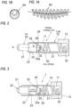
FIGS. 1A and 1B are views of a coil spring used in a spring connector in the related art, in whichFIG. 1A is a front view, andFIG. 1B is a left side view. -
FIG. 2 is an explanatory view ofEmbodiment 1 of a spring connector according to the present invention when no load is applied to a pin. -
FIG. 3 is an explanatory view of a state in which the same pin is pushed toward a tube side by a load applied to the pin. -
FIGS. 4A and 4B are views of a coil spring used inEmbodiment 1, in whichFIG. 4A is a front view, andFIG. 4B is a left side view. -
FIGS. 5A and 5B are views of a main part according toEmbodiment 1, in whichFIG. 5A is an explanatory view of a main part of the spring connector, andFIG. 5B is a side view of a side of the coil spring in contact with the pin. -
FIG. 6 is an explanatory view showing a conduction path when the pin is pushed inEmbodiment 1. -
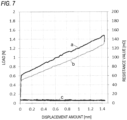
FIG. 7 is a graph showing a relation between a displacement amount [mm], a load [N], and a resistance value [mΩ] due to the pushing of the pin inEmbodiment 1. -
FIG. 8 is an explanatory view showing a usage example of the spring connector shown inEmbodiment 1. -
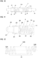
FIGS. 9A and 9B are views of a main part according toEmbodiment 2 of the present invention, in whichFIG. 9A is an explanatory view of a main part of the spring connector, andFIG. 9B is a side view of a side of the coil spring in contact with the pin. -
FIG. 10 is an explanatoryview showing Embodiment 3 of the spring connector according to the present invention. -
FIG. 11 is an explanatoryview showing Embodiment 4 of the spring connector according to the present invention. -
FIG. 12 is a front view showing a modification of the coil spring used in the spring connector according to the present invention. - Hereinafter, preferred embodiments of the present invention will be described in detail with reference to the drawings. The same or equivalent components, members, processes, and the like shown in the drawings are denoted by the same reference numerals, and redundant description thereof will be omitted as appropriate. The embodiments are not intended to limit the invention but are mere exemplifications, and all features and combinations thereof described in the embodiments are not necessarily essential features of the invention.
-
Embodiment 1 of a spring connector according to the present invention will be described with reference toFIGS. 2 to 7 . In the drawings, aspring connector 1 includes aconductive tube 10, aconductive pin 20 that is slidable in thetube 10, and acoil spring 30 provided in thetube 10. - The
tube 10 has a bottomed cylindrical shape having a cylindricalhollow portion 11 inside, and a base portion thereof is aflange portion 12 having a wide width. Theflange portion 12 is a portion fixed to an electrode of a substrate or the like by soldering or the like. - The
pin 20 includes a protrudingportion 21 that protrudes from the inside of thetube 10 to the outside of thetube 10 and serves as an external contact portion, and aninlet pipe portion 22 inserted into thetube 10 and positioned in the cylindricalhollow portion 11. Theinlet pipe portion 22 is a portion of thepin 20 that enters thetube 10, and includes a slidingportion 23 that faces an inner wall of the cylindricalhollow portion 11 of thetube 10 and is slidable. When an axis that passes through a center of thepin 20 and is substantially parallel to a sliding direction of thepin 20 is defined as a pin central axis α, and aconical portion 24 that is rotationally symmetrical with respect to the pin central axis α is formed on an end surface of theinlet pipe portion 22 on a side opposite to the side at which the protrudingportion 21 is provided. Theconical portion 24 protrudes in a direction opposite to a direction in which the protrudingportion 21 of thepin 20 protrudes, and an angle θ formed by avertical surface 29 with respect to the pin central axis α and a surface of theconical portion 24 is approximately 45°. The angle θ is not limited to about 45° and can be appropriately set within a range of 30° to 60°. - A
boundary portion 25 between the slidingportion 23 and theconical portion 24 of thepin 20 has a curved shape having a predetermined curvature. Theinlet pipe portion 22 is larger in diameter than the protrudingportion 21, and an opening diameter of a distal end portion of thetube 10 is processed so that theinlet pipe portion 22 does not come out of the cylindricalhollow portion 11 and fall off, that is, the opening diameter is smaller in diameter than theinlet pipe portion 22. - The
coil spring 30 is formed by winding an elastic metal wire, and functions as a compression spring to bias thepin 20 in a direction in which thepin 20 protrudes from thetube 10. As shown inFIG. 4A and FIG. 4B , thecoil spring 30 includes a roughly woundportion 31 wound to have a constant outer diameter, and densely woundportions 32 positioned on both end portion sides of the roughly woundportion 31. The densely woundportions 32 form an end wound portion, and one of the densely woundportion 32 is engaged with theconical portion 24 of thepin 20. However, the densely woundportion 32 is not limited to an end-turning state, and may be in a more densely wound state than the roughly woundportion 31. The roughly woundportion 31 is a portion functioning as a spring at the time of compression and generates a force in a direction in which thepin 20 protrudes out of thetube 10 at the time of compression. The outer diameter of the roughly woundportion 31 is, for example, 1.15 mm and is slightly smaller than an inner diameter of the cylindricalhollow portion 11, and a central axis β of the roughly woundportion 31 is not curved and substantially maintains a straight line. An outer diameter of the densely woundportion 32 is, for example, 0.8 mm and is smaller than the outer diameter of the roughly woundportion 31, and an inner diameter of the densely woundportion 32 is larger than a radius of the slidingportion 23 of thepin 20. The outer diameters of the roughly woundportion 31 and the densely woundportion 32 are not limited to the above values. The central axis β of the roughly woundportion 31 and a central axis γ of the densely woundportion 32 are different from each other, and the central axes are formed to be substantially parallel to each other over the entire length of thecoil spring 30. In other words, the central axis γ of the densely woundportion 32 is offset (eccentric) with respect to the central axis β of the roughly woundportion 31. Thepin 20 and thecoil spring 30 are engaged with each other in a state at which an apex of theconical portion 24 is positioned inside the inner diameter of the densely woundportion 32. - In the example of
FIG. 4A and FIG. 4B , thecoil spring 30 is in a no-load state, and the central axes γ of the densely woundportions 32 provided on both end sides of the roughly woundportion 31 are coaxial with each other. In manufacturing, a case in which there is a tolerance between the central axes of the densely woundportions 32 at both ends is regarded as being coaxial. When the central axis β of the roughly woundportion 31 is viewed from a protruding side of the pin 20 (hereinafter, referred to as viewed from a central axis β direction), an outer peripheral end of the roughly woundportion 31 and an outer peripheral end of the densely woundportion 32 are aligned with each other on an outer side in a direction (eccentric direction) in which the central axis γ of the densely woundportion 32 is offset with respect to the central axis β of the roughly woundportion 31. In other words, as shown in a left side view of (B) ofFIG. 4 , an outer peripheral circle of the densely woundportion 32 is inscribed in an outer peripheral circle of the roughly woundportion 31. The winding number of the densely woundportion 32 is 1.5 windings. A cuttingend portion 32a of the densely woundportion 32 of thecoil spring 30 is positioned on an outer side in a direction in which the central axis γ of the densely woundportion 32 is offset with respect to the central axis β of the roughly woundportion 31. That is, the cuttingend portion 32a is positioned closer to the inner wall side of thetube 10 than the central axis γ of the densely woundportion 32. - When the
pin 20 and thecoil spring 30 are accommodated in the cylindricalhollow portion 11 of thetube 10, a distal end of theconical portion 24 of thepin 20 is positioned inside the inner diameter of the densely woundportion 32, during assembly, the distal end of theconical portion 24 is inducted into the densely woundportion 32 of theeccentric coil spring 30, and the densely woundportion 32 engages with theconical portion 24. - The
tube 10 and thepin 20 are subjected to a plating process to maintain good conductivity. For example, the base is nickel (Ni) plating, and the surface is gold (Au) plating. - In the configuration of
Embodiment 1 described above, when thepin 20 is pressed against the electrode or the like of an opposite device from the no-load state ofFIG. 2 , thepin 20 is pushed into thetube 10 as shown inFIG. 3 . Accordingly, both ends of thecoil spring 30 are compressed by theconical portion 24 of thepin 20 and the bottom surface of thetube 10. At this time, since the distal end of theconical portion 24 of thepin 20 is positioned inside the inner diameter of the eccentric densely woundportion 32 as shown inFIG. 5A , theconical portion 24 is pressed at apressing position 32b on an inner periphery of the densely woundportion 32 as shown inFIG. 5B . As a result, thecoil spring 30 is compressed in a state in which an offset amount of the central axis γ of the densely woundportion 32 with respect to the central axis β of the roughly woundportion 31 is reduced. Thecoil spring 30 generates a force to return from a compressed state to the state ofFIG. 4B when no load is applied (a state in which the outer peripheral end of the roughly woundportion 31 and the outer peripheral end of the densely woundportion 32 are aligned on the outer side in the offset direction (eccentric direction)). As a result, a lateral pressure is generated in a direction of an arrow inFIG. 3 , and theboundary portion 25 between the slidingportion 23 and theconical portion 24 of thepin 20 is normally in contact with an inner wall surface of thetube 10. As shown inFIG. 6 , the conduction path of thespring connector 1 is a path of thepin 20, theboundary portion 25 of thepin 20 pressed against the inner wall surface of thetube 10 by the lateral pressure, and thetube 10. - Next, the fact that the lateral pressure for pressing the
pin 20 against the inner wall surface of thetube 10 is stable regardless of the compression amount of thecoil spring 30 will be described with reference toFIG. 7 . An upper inclined line a inFIG. 7 represents a relation between the pin displacement amount [mm] and the load [N] when thepin 20 is pushed from the displacement amount of 0 mm to about 1.45 mm by applying a load thereto, and the load at this time is [reaction force of thecoil spring 30 + frictional force (depending on the lateral pressure) at the time of pushing]. A lower inclined line b inFIG. 7 represents a relation between the pin displacement amount [mm] and the load [N] when the load of thepin 20 is reduced to return the displacement amount from about 1.45 mm to 0 mm, and the load at this time is [reaction force of the coil spring 30 - frictional force (depending on the lateral pressure) at the time of pushing]. Accordingly, it is understood that, at any displacement amount of thepin 20, a difference between the upper inclined line a and the lower inclined line b becomes an amount depending on the lateral pressure, and even when the displacement amount is changed, the difference between the upper inclined line a and the lower inclined line b does not greatly change, and the lateral pressure is stable. -
FIG. 7 shows a relation between the pin displacement amount [mm] and a resistance value [mΩ] by a line c. Since the lateral pressure is stable regardless of the displacement amount of the pin, it can be understood that the resistance value is substantially constant and stable at a sufficiently low value even when the displacement amount changes. -
FIG. 8 is an explanatory view showing an usage example of thespring connector 1 shown inEmbodiment 1. Thespring connector 1 is fixed to a conductor electrode portion such as asubstrate 40 of an electric device or an electronic device by soldering or the like at theflange portion 12 of thetube 10. By pressing thepin 20 of thespring connector 1 against anelectrode terminal 52 provided on ahousing 51 of anopposite device 50, detachable electrical connection with theelectrode terminal 52 of theopposite device 50 can be made. In this case, thespring connector 1 can be used to connect a signal line, a power supply line, or the like. - According to the present embodiment, the following effects can be achieved.
- (1) The
coil spring 30 for biasing thepin 20 in the direction in which thepin 20 protrudes out of thetube 10 includes the roughly woundportion 31 and the densely woundportions 32 each positioned on the end portion side of the roughly woundportion 31 and engaged with thepin 20, the diameter of the densely woundportion 32 is smaller than the diameter of the roughly woundportion 31, and the central axis γ of the densely woundportion 32 and the central axis β of the roughly woundportion 31 are different from each other. That is, the densely woundportion 32 is eccentric with respect to the roughly woundportion 31, and when thepin 20 is pushed in, an eccentricity amount of the densely woundportion 32 is changed by engaging with theconical portion 24, and the lateral pressure for pressing thepin 20 against the tube inner wall surface is generated. Since the lateral pressure is generated substantially only by the eccentricity of the densely woundportion 32 with respect to the roughly woundportion 31, as shown by the difference between the upper inclined line a and the lower inclined line b inFIG. 7 , it is possible to secure a substantially constant and stable lateral pressure from initial pushing without depending on the compression amount of thepin 20 in the axial direction. - (2) The
pin 20 includes theinlet pipe portion 22 positioned in thetube 10, and theinlet pipe portion 22 includes theconical portion 24 that engages with the densely woundportion 32 of thecoil spring 30. Since theconical portion 24 is rotationally symmetric with respect to the central axis α of thepin 20, secondary machining is not required in general lathe machining. That is, thepin 20 can be processed more easily than when the pin bottom surface is obliquely bias-cut. Although the lateral pressure function is established even when the angle θ of theconical portion 24 is 30° to 60°, approximately 45° is optimum in consideration of securing a contact portion with thetube 10 and wear during sliding. - (3) The
coil spring 30 includes the roughly woundportion 31 and the densely woundportions 32 each positioned on the end portion side of the roughly woundportion 31 and engaged with theconical portion 24 of thepin 20, since theconical portion 24 of thepin 20 is inducted into and engaged with the eccentric densely woundportion 32 during assembly, the assemblability is excellent. Further, since theconical portion 24 is engaged with the inside of the inner diameter of the densely woundportion 32 to be stably fitted, thepin 20 does not rattle. - (4) Since the
boundary portion 25 between the slidingportion 23 and theconical portion 24 in theinlet pipe portion 22 of thepin 20 inserted into thetube 10 has a curved shape, wear resistance between theboundary portion 25 and the inner wall of the cylindricalhollow portion 11 of thetube 10 in sliding contact is improved, and deterioration of a product can be prevented. - (5) Since the outer peripheral end of the roughly wound
portion 31 and the outer peripheral end of the densely woundportion 32 are aligned on the outer side in the direction in which the central axis γ of the densely woundportion 32 is offset with respect to the central axis β of the roughly woundportion 31, the eccentricity amount when the induction of the densely woundportion 32 by theconical portion 24 of thepin 20 is taken into consideration is maximized, and the lateral pressure can be maximized. However, even when the outer peripheral end of the roughly woundportion 31 and the outer peripheral end of the densely woundportion 32 are not aligned with each other, the lateral pressure can be stabilized. - (6) The winding number of the densely wound
portion 32 of thecoil spring 30 is 1.5 windings, and the cuttingend portion 32a is positioned on the outer side in the direction in which the central axis γ of the densely woundportion 32 is offset when viewed from the central axis β direction of the roughly woundportion 31, and thus the engagement and contact between the densely woundportion 32 and theconical portion 24 of thepin 20 is reliable. In terms of operation principle, the winding number of the densely woundportion 32 may be 2, 2.5, or the like, but 1.5 windings is preferable in that the total length of thecoil spring 30 does not become long and sufficient lateral pressure can be generated. - (7) The densely wound
portions 32 of thecoil spring 30 are symmetrically provided on both end sides of the roughly woundportion 31. That is, the densely woundportions 32 provided on both end sides of the roughly woundportion 31 have the same central axes γ, the same eccentricity amount, and the same winding number, and thus the assemblability is good since the same performance is obtained even in an upside-down state. It is not necessary to consider an insertion direction of thecoil spring 30 into thetube 10 during assembly. The assembly is realized by insertingcoil spring 30 and thepin 20 into thetube 10 in this order, but since theconical portion 24 of thepin 20 is inducted into and engaged with the densely woundportion 32 of theeccentric coil spring 30, in this respect, the assemblability is also excellent. - (8) Since the central axis β of the roughly wound
portion 31 of thecoil spring 30 is substantially parallel to the central axis γ of the densely woundportion 32 and the central axis β of the roughly woundportion 31 is substantially a straight line, the roughly woundportion 31 hardly affects the lateral pressure when the roughly woundportion 31 is compressed, and the lateral pressure can be stabilized regardless of the compression amount of the roughly woundportion 31, that is, the push-in displacement amount of thepin 20. -
FIG. 9A and FIG. 9B are views of a main part according toEmbodiment 2 of the spring connector of the present invention, in whichFIG. 9A is an explanatory view of a main part of thespring connector 2, andFIG. 9B is a side view of a side of acoil spring 30A in contact with the pin. In this case, the winding number of the densely woundportion 32 in acoil spring 30A is 1, and a cuttingend portion 32c is positioned on a side opposite to the central axis γ of the densely woundportion 32 that is offset with respect to the central axis β of the roughly woundportion 31. - According to
Embodiment 2, since the winding number of the densely woundportion 32 is 1, the total length of thecoil spring 30A can be shortened. The stability of engagement and contact between the densely woundportion 32 and theconical portion 24 of thepin 20 is better than the winding number of 1.5. Other configurations, operations, and effects are the same as those ofEmbodiment 1. -
FIG. 9A and FIG. 9B show a case in which the winding number of the densely woundportion 32 is 1, and inEmbodiment 1, the winding number of the densely woundportion 32 is 1.5, and may be 1.5 or more. -
FIG. 10 is an explanatoryview showing Embodiment 3 of the spring connector according to the present invention. In this case, thespring connector 3 includes aconductive tube 10A having a cylindrical penetratedhollow portion 11A, thecoil spring 30 provided in the cylindrical penetratedhollow portion 11A, and a pair ofconductive pins 20 slidable in thetube 10, and thepins 20 are provided on both sides of thecoil spring 30. Configurations, operations, and effects other than that thepin 20 is disposed on both sides of thecoil spring 30 are the same as those ofEmbodiment 1 described above. - According to
Embodiment 3, since thepins 20 protrude from both sides of thetube 10A, for example, thepins 20 can be used as probes in which one pin is brought into contact with an electrode of an object to be measured such as an integrated circuit and the other pin is brought into contact with an electrode of an inspection substrate of a measurement device. -
FIG. 11 is an explanatoryview showing Embodiment 4 of the spring connector according to the present invention. In this case, thespring connector 4 is different fromEmbodiment 1 in the shape of theconductive pin 20. That is, in thepin 20 ofEmbodiment 4, a portion (width wide portion) of theconical portion 24 ofEmbodiment 1 that is not directly engaged with thecoil spring 30 is omitted, and an end surface of thepin 20 on a side facing thecoil spring 30 has a circular ring-shapedflat surface portion 26 surrounding theconical portion 24. For example, a boundary portion between the slidingportion 23 and theflat surface portion 26 of thepin 20 has a curved shape. Other configurations are the same as those ofEmbodiment 1. - According to
Embodiment 4, in addition to the effects ofEmbodiment 1, the entire length of thespring connector 4 can be shortened by omitting the width wide portion of theconical portion 24 to reduce the height. By shortening the length, processing time and a material can be reduced. An overall length of thecoil spring 30 can be shortened while optimally maintaining an angle of a fitting portion (approximately 90°) of thecoil spring 30 in theconical part 24. Although the angle formed by the inner wall of the cylindricalhollow portion 11 of thetube 10 and theflat surface portion 26 is 90°, the boundary portion between the slidingportion 23 and theflat surface portion 26 of thepin 20 has a curved shape, and thus good sliding properties and wear resistance can be maintained. - Although the present invention has been described with reference to the embodiments, it is to be understood by those skilled in the art that various modifications can be made to the components and the processes of the embodiments within the scope of the claims. Hereinafter, modifications will be described.
-
FIG. 12 is a front view showing a modification of the coil spring usable in the spring connector of the present invention. In this case, in acoil spring 30B, a densely woundportion 32A on one end portion side of the roughly woundportion 31 is offset (eccentric) to one end portion side with respect to the central axis of the roughly woundportion 31, and the densely woundportion 32B on the other side is offset (eccentric) to the other side with respect to the central axis of the roughly woundportion 31. InEmbodiment 1 and the like, even when thecoil spring 30B is used instead of thecoil spring 30, the same effects as those ofEmbodiment 1 and the like can be obtained. - Embodiments and modifications of the present invention have been described above with reference to the drawings, but these are examples of the present invention, and various configurations other than those described above can also be adopted.
-
- 1, 2, 3 spring connector
- 10, 10A tube
- 11 cylindrical hollow portion
- 11A cylindrical penetrated hollow portion
- 12 flange portion
- 20 pin
- 21 protruding portion
- 22 inlet pipe portion
- 23 sliding portion
- 24 conical portion
- 25 boundary portion
- 26 flat surface portion
- 30, 30A, 30B coil spring
- 31 roughly wound portion
- 32, 32A, 32B densely wound portion
- 40 substrate
- 50 opposite device
- α central axis of pin
- β central axis of roughly wound portion
- y central axis of densely wound portion
Claims (11)
- A spring connector comprising:a conductive tube;a conductive pin being slidable in the tube; anda spring provided in the tube and configured to bias the pin in a direction in which the pin protrudes from the tube, whereinthe spring includes a roughly wound portion and a densely wound portion positioned on an end portion side of the roughly wound portion and engaged with the pin, anda diameter of the densely wound portion is smaller than a diameter of the roughly wound portion, and a central axis of the densely wound portion and a central axis of the roughly wound portion are different from each other.
- The spring connector according to claim 1, whereinthe pin includes a protruding portion protruding outside of the tube and an inlet pipe portion positioned in the tube, andthe inlet pipe portion includes a sliding portion that is slidable with respect to an inner wall of the tube and a conical portion engaged with the densely wound portion of the spring.
- The spring connector according to claim 2, wherein
a boundary portion between the sliding portion and the conical portion has a curved shape. - The spring connector according to any one of claims 1 to 3, wherein
an outer peripheral end of the roughly wound portion and an outer peripheral end of the densely wound portion are aligned on an outer side in a direction in which the central axis of the densely wound portion is offset with respect to the central axis of the roughly wound portion. - The spring connector according to any one of claims 1 to 3, wherein
the densely wound portion is provided on each of both end sides of the roughly wound portion. - The spring connector according to claim 5, wherein
central axes of the densely wound portions provided on both end sides of the roughly wound portion are offset in the same direction with respect to the central axis of the roughly wound portion. - The spring connector according to claim 5, wherein
central axes of the densely wound portions provided on both end sides of the roughly wound portion are coaxial with each other. - The spring connector according to claim 5, wherein
central axes of the densely wound portions provided on both end sides of the roughly wound portion are offset in opposite directions across a central axis of the roughly wound portion. - The spring connector according to any one of claims 1 to 3, wherein
a cutting end portion of the spring is positioned closer to an inner wall side of the tube than the central axis of the densely wound portion in a direction in which the central axis of the densely wound portion is offset from the central axis of the roughly wound portion. - The spring connector according to any one of claims 1 to 3, wherein
the central axis of the densely wound portion and the central axis of the roughly wound portion are substantially parallel to each other. - The spring connector according to claim 2 or 3, wherein
the inlet pipe portion has a flat surface portion surrounding the conical portion on an end surface facing the spring.
Applications Claiming Priority (2)
| Application Number | Priority Date | Filing Date | Title |
|---|---|---|---|
| JP2022049334 | 2022-03-25 | ||
| PCT/JP2023/008486 WO2023181906A1 (en) | 2022-03-25 | 2023-03-07 | Spring connector |
Publications (2)
| Publication Number | Publication Date |
|---|---|
| EP4502624A1 true EP4502624A1 (en) | 2025-02-05 |
| EP4502624A4 EP4502624A4 (en) | 2026-03-18 |
Family
ID=88100748
Family Applications (1)
| Application Number | Title | Priority Date | Filing Date |
|---|---|---|---|
| EP23774505.4A Pending EP4502624A4 (en) | 2022-03-25 | 2023-03-07 | Spring connector |
Country Status (5)
| Country | Link |
|---|---|
| EP (1) | EP4502624A4 (en) |
| JP (1) | JPWO2023181906A1 (en) |
| CN (1) | CN118946811A (en) |
| TW (1) | TW202416596A (en) |
| WO (1) | WO2023181906A1 (en) |
Families Citing this family (1)
| Publication number | Priority date | Publication date | Assignee | Title |
|---|---|---|---|---|
| WO2025186464A1 (en) | 2024-03-08 | 2025-09-12 | Preci-Dip Sa | Electrical contact having a self-cleaning contact piston |
Family Cites Families (12)
| Publication number | Priority date | Publication date | Assignee | Title |
|---|---|---|---|---|
| JPH1145746A (en) * | 1997-07-28 | 1999-02-16 | Yokowo Co Ltd | Conductive contact piece |
| JP3597738B2 (en) * | 1999-03-12 | 2004-12-08 | 日本発条株式会社 | Conductive contact and conductive contact assembly |
| JP4614434B2 (en) * | 2004-09-30 | 2011-01-19 | 株式会社ヨコオ | probe |
| JP2006153723A (en) * | 2004-11-30 | 2006-06-15 | Japan Electronic Materials Corp | Vertical coil spring probe and probe unit using the same |
| US7362118B2 (en) * | 2006-08-25 | 2008-04-22 | Interconnect Devices, Inc. | Probe with contact ring |
| JP5361710B2 (en) * | 2007-04-19 | 2013-12-04 | 日本発條株式会社 | Conductive contact and conductive contact unit |
| JP5197754B2 (en) | 2009-11-13 | 2013-05-15 | テスト ツーリング ソリューションズ グループ ピイ ティ イー リミテッド | Probe pin |
| JP5987447B2 (en) * | 2012-04-23 | 2016-09-07 | 株式会社デンソー | Inspection device |
| US9910069B1 (en) * | 2015-04-24 | 2018-03-06 | Kita Usa | Biasing method and device construction for a spring probe |
| PH12019502217B1 (en) * | 2017-03-30 | 2024-04-17 | Nhk Spring Co Ltd | Contact probe and probe unit |
| CN207798901U (en) * | 2018-01-26 | 2018-08-31 | 平湖市日拓电子科技有限公司 | A kind of probe |
| JP2021072192A (en) * | 2019-10-30 | 2021-05-06 | 株式会社ヨコオ | Spring connector and manufacturing method thereof |
-
2023
- 2023-03-07 CN CN202380028963.XA patent/CN118946811A/en active Pending
- 2023-03-07 TW TW112108329A patent/TW202416596A/en unknown
- 2023-03-07 WO PCT/JP2023/008486 patent/WO2023181906A1/en not_active Ceased
- 2023-03-07 EP EP23774505.4A patent/EP4502624A4/en active Pending
- 2023-03-07 JP JP2024509956A patent/JPWO2023181906A1/ja active Pending
Also Published As
| Publication number | Publication date |
|---|---|
| JPWO2023181906A1 (en) | 2023-09-28 |
| WO2023181906A1 (en) | 2023-09-28 |
| EP4502624A4 (en) | 2026-03-18 |
| TW202416596A (en) | 2024-04-16 |
| CN118946811A (en) | 2024-11-12 |
Similar Documents
| Publication | Publication Date | Title |
|---|---|---|
| US11355881B2 (en) | Electrical connector housing, electrical connector and electrical connector assembly | |
| JP5197754B2 (en) | Probe pin | |
| CN101501509B (en) | Electrical contact probe with compliant internal interconnect | |
| KR101894965B1 (en) | Probe pin and ic socket | |
| JP5361518B2 (en) | Contact probe and socket | |
| EP2836847B1 (en) | Test probe assembly and related methods | |
| US8408946B1 (en) | Low inductance contact with conductively coupled pin | |
| US7249981B2 (en) | Press-fit pin | |
| JP5131766B2 (en) | Incorrect insertion prevention type Kelvin inspection jig | |
| CN109387672B (en) | coaxial probe | |
| EP1299735A2 (en) | Self-retained spring probe | |
| TWI743590B (en) | Probe | |
| CN107251332A (en) | Low passive intermodulation coaxial connector test interface | |
| WO2020064611A1 (en) | Spring pin connector | |
| US10770817B2 (en) | Terminal module | |
| WO2003103095A1 (en) | Electrical connector | |
| WO2023181906A1 (en) | Spring connector | |
| KR20110131234A (en) | Inspection Coaxial Connector | |
| JP7605717B2 (en) | Probes and Test Sockets | |
| US11394148B2 (en) | Contact probe and inspection socket provided with contact probe | |
| US10756473B2 (en) | Connection terminal | |
| US20220416462A1 (en) | Spring connector | |
| US20230178906A1 (en) | Spring connector | |
| JP2023173519A (en) | probe | |
| US20250385457A1 (en) | Connector |
Legal Events
| Date | Code | Title | Description |
|---|---|---|---|
| STAA | Information on the status of an ep patent application or granted ep patent |
Free format text: STATUS: THE INTERNATIONAL PUBLICATION HAS BEEN MADE |
|
| PUAI | Public reference made under article 153(3) epc to a published international application that has entered the european phase |
Free format text: ORIGINAL CODE: 0009012 |
|
| STAA | Information on the status of an ep patent application or granted ep patent |
Free format text: STATUS: REQUEST FOR EXAMINATION WAS MADE |
|
| 17P | Request for examination filed |
Effective date: 20240920 |
|
| AK | Designated contracting states |
Kind code of ref document: A1 Designated state(s): AL AT BE BG CH CY CZ DE DK EE ES FI FR GB GR HR HU IE IS IT LI LT LU LV MC ME MK MT NL NO PL PT RO RS SE SI SK SM TR |
|
| DAV | Request for validation of the european patent (deleted) | ||
| DAX | Request for extension of the european patent (deleted) | ||
| A4 | Supplementary search report drawn up and despatched |
Effective date: 20260217 |
|
| RIC1 | Information provided on ipc code assigned before grant |
Ipc: G01R 1/067 20060101AFI20260211BHEP Ipc: H01R 13/24 20060101ALI20260211BHEP Ipc: F16F 1/04 20060101ALI20260211BHEP Ipc: G01R 1/073 20060101ALN20260211BHEP Ipc: H01R 12/73 20110101ALN20260211BHEP |