EP4502619A1 - Automatic analysis device - Google Patents
Automatic analysis device Download PDFInfo
- Publication number
- EP4502619A1 EP4502619A1 EP23778831.0A EP23778831A EP4502619A1 EP 4502619 A1 EP4502619 A1 EP 4502619A1 EP 23778831 A EP23778831 A EP 23778831A EP 4502619 A1 EP4502619 A1 EP 4502619A1
- Authority
- EP
- European Patent Office
- Prior art keywords
- reagent
- dispensing mechanism
- analysis device
- automatic analysis
- reagent dispensing
- Prior art date
- Legal status (The legal status is an assumption and is not a legal conclusion. Google has not performed a legal analysis and makes no representation as to the accuracy of the status listed.)
- Pending
Links
Images






Classifications
-
- G—PHYSICS
- G01—MEASURING; TESTING
- G01N—INVESTIGATING OR ANALYSING MATERIALS BY DETERMINING THEIR CHEMICAL OR PHYSICAL PROPERTIES
- G01N35/00—Automatic analysis not limited to methods or materials provided for in any single one of groups G01N1/00 - G01N33/00; Handling materials therefor
- G01N35/10—Devices for transferring samples or any liquids to, in, or from, the analysis apparatus, e.g. suction devices, injection devices
- G01N35/1002—Reagent dispensers
-
- G—PHYSICS
- G01—MEASURING; TESTING
- G01N—INVESTIGATING OR ANALYSING MATERIALS BY DETERMINING THEIR CHEMICAL OR PHYSICAL PROPERTIES
- G01N35/00—Automatic analysis not limited to methods or materials provided for in any single one of groups G01N1/00 - G01N33/00; Handling materials therefor
- G01N35/02—Automatic analysis not limited to methods or materials provided for in any single one of groups G01N1/00 - G01N33/00; Handling materials therefor using a plurality of sample containers moved by a conveyor system past one or more treatment or analysis stations
- G01N35/025—Automatic analysis not limited to methods or materials provided for in any single one of groups G01N1/00 - G01N33/00; Handling materials therefor using a plurality of sample containers moved by a conveyor system past one or more treatment or analysis stations having a carousel or turntable for reaction cells or cuvettes
-
- G—PHYSICS
- G01—MEASURING; TESTING
- G01N—INVESTIGATING OR ANALYSING MATERIALS BY DETERMINING THEIR CHEMICAL OR PHYSICAL PROPERTIES
- G01N35/00—Automatic analysis not limited to methods or materials provided for in any single one of groups G01N1/00 - G01N33/00; Handling materials therefor
- G01N35/02—Automatic analysis not limited to methods or materials provided for in any single one of groups G01N1/00 - G01N33/00; Handling materials therefor using a plurality of sample containers moved by a conveyor system past one or more treatment or analysis stations
- G01N35/04—Details of the conveyor system
-
- G—PHYSICS
- G01—MEASURING; TESTING
- G01N—INVESTIGATING OR ANALYSING MATERIALS BY DETERMINING THEIR CHEMICAL OR PHYSICAL PROPERTIES
- G01N35/00—Automatic analysis not limited to methods or materials provided for in any single one of groups G01N1/00 - G01N33/00; Handling materials therefor
- G01N35/10—Devices for transferring samples or any liquids to, in, or from, the analysis apparatus, e.g. suction devices, injection devices
- G01N35/1009—Characterised by arrangements for controlling the aspiration or dispense of liquids
- G01N35/1016—Control of the volume dispensed or introduced
-
- G—PHYSICS
- G01—MEASURING; TESTING
- G01N—INVESTIGATING OR ANALYSING MATERIALS BY DETERMINING THEIR CHEMICAL OR PHYSICAL PROPERTIES
- G01N35/00—Automatic analysis not limited to methods or materials provided for in any single one of groups G01N1/00 - G01N33/00; Handling materials therefor
- G01N2035/00346—Heating or cooling arrangements
-
- G—PHYSICS
- G01—MEASURING; TESTING
- G01N—INVESTIGATING OR ANALYSING MATERIALS BY DETERMINING THEIR CHEMICAL OR PHYSICAL PROPERTIES
- G01N35/00—Automatic analysis not limited to methods or materials provided for in any single one of groups G01N1/00 - G01N33/00; Handling materials therefor
- G01N2035/00346—Heating or cooling arrangements
- G01N2035/00425—Heating or cooling means associated with pipettes or the like, e.g. for supplying sample/reagent at given temperature
-
- G—PHYSICS
- G01—MEASURING; TESTING
- G01N—INVESTIGATING OR ANALYSING MATERIALS BY DETERMINING THEIR CHEMICAL OR PHYSICAL PROPERTIES
- G01N35/00—Automatic analysis not limited to methods or materials provided for in any single one of groups G01N1/00 - G01N33/00; Handling materials therefor
- G01N35/00584—Control arrangements for automatic analysers
- G01N35/0092—Scheduling
- G01N2035/0094—Scheduling optimisation; experiment design
-
- G—PHYSICS
- G01—MEASURING; TESTING
- G01N—INVESTIGATING OR ANALYSING MATERIALS BY DETERMINING THEIR CHEMICAL OR PHYSICAL PROPERTIES
- G01N35/00—Automatic analysis not limited to methods or materials provided for in any single one of groups G01N1/00 - G01N33/00; Handling materials therefor
- G01N35/02—Automatic analysis not limited to methods or materials provided for in any single one of groups G01N1/00 - G01N33/00; Handling materials therefor using a plurality of sample containers moved by a conveyor system past one or more treatment or analysis stations
- G01N35/04—Details of the conveyor system
- G01N2035/0439—Rotary sample carriers, i.e. carousels
- G01N2035/0443—Rotary sample carriers, i.e. carousels for reagents
-
- G—PHYSICS
- G01—MEASURING; TESTING
- G01N—INVESTIGATING OR ANALYSING MATERIALS BY DETERMINING THEIR CHEMICAL OR PHYSICAL PROPERTIES
- G01N35/00—Automatic analysis not limited to methods or materials provided for in any single one of groups G01N1/00 - G01N33/00; Handling materials therefor
- G01N35/10—Devices for transferring samples or any liquids to, in, or from, the analysis apparatus, e.g. suction devices, injection devices
- G01N35/1004—Cleaning sample transfer devices
Definitions
- the present invention relates to an automatic analysis device.
- a sample and a reagent are dispensed and mixed, and the obtained mixed liquid is used for measurement.
- a pipetting type is generally known as a reagent dispensing method.
- a dispensing mechanism of a pipetting type aspirates a reagent from a reagent container, then rises, rotates horizontally, and then descends to discharge the reagent into a reaction container.
- the reagent dispensing mechanism of the pipetting type is suitable for dispensing various reagents, but is not suitable for adjusting a temperature of a reagent.
- a temperature of a reagent is adjusted in an automatic analysis device adopting a dispensing mechanism of a pipetting type, as described in PTL 1, it is necessary to incorporate a heater in the dispensing mechanism itself or to temporarily dispense the reagent into another reaction container or the like to raise the temperature for a certain period of time.
- an amount of reagent that can be dispensed at one time is limited. Therefore, in the reagent dispensing mechanism of the pipetting type, preparations before analysis such as adjusting the temperature of the reagent and dispensing an appropriate amount of reagent tend to take time, and as a result, an analysis time may become long.
- the purpose of the invention is to provide an automatic analysis device by which it is possible to shorten analysis time while guaranteeing use of various reagents.
- this automatic analysis device includes: a first reagent dispensing mechanism of a pipetting type that, upon aspirating a reagent, moves to a prescribed location away from the reagent and then discharges the reagent; and a second reagent dispensing mechanism of a dispensing type that supplies a reagent via a flow path connecting an aspirating port to a discharge port for the reagent.
- the second reagent dispensing mechanism includes a temperature adjustment mechanism that adjusts a temperature of the reagent.
- FIG. 1 is a plan view showing a schematic configuration of an automatic analysis device according to Embodiment 1.
- the automatic analysis device according to the present embodiment mainly includes a reaction disc 1, a sample conveyance mechanism 8, a sample dispensing mechanism 3, a reagent disc 9 including a reaction container 2, a first reagent dispensing mechanism 100, a second reagent dispensing mechanism 200, and a stirring mechanism 5.
- the automatic analysis device according to the present embodiment includes a measurement unit that measures transmitted light and scattered light of a mixed liquid of a sample and a reagent, and a control unit that controls each mechanism. In the present embodiment, an example in which the measurement unit measures transmitted light or scattered light will be described.
- the measurement unit may measure potential, electrical resistance, chemiluminescence, fluorescence, and the like, and is not limited to a measurement method.
- the measurement unit is not limited to measurement of the mixed liquid contained in the reaction container 2, and the measurement unit may measure the mixed liquid after moving the mixed liquid from the reaction container 2 to the measurement unit using a nozzle, a flow path, or the like for solution transportation.
- the reaction disc 1 includes a plurality of reaction containers 2 for reacting a sample and a reagent, in a state of being separated from each other at predetermined intervals along a circumferential direction thereof (circumferentially), and rotates in a direction indicated by an arrow Z in FIG. 1 .
- the sample conveyance mechanism 8 is provided near the reaction disc 1 and conveys a rack 7 on which a sample container 6 is placed.
- the sample dispensing mechanism aspirates the sample contained in the sample container 6 and discharges the sample to the reaction container 2, and is capable of vertical movement and horizontal rotation.
- the reagent disc 9 is a storage on which a plurality of reagent containers 10 containing reagents are placed in a circumferential shape, and is kept cool as necessary.
- the first reagent dispensing mechanism 100 is a mechanism for dispensing the reagent by pipetting type.
- the first reagent dispensing mechanism 100 Aspirates the reagent (first reagent) contained in the reagent container 10 on the reagent disc 9, the first reagent dispensing mechanism 100 rises to separate from the reagent, rotates to a reagent discharge position on the reaction disc 1, and then descends to discharge the reagent to the reaction container 2.
- the first reagent dispensing mechanism 100 is washed by the first reagent dispensing mechanism washing mechanism 101.
- the second reagent dispensing mechanism 200 is a mechanism for dispensing the reagent by a dispensing type, and supplies the reagent (second reagent) through a flow path connected from an aspirating port to a discharge port for the reagent.
- the discharge port of the second reagent dispensing mechanism 200 includes a plurality of reagent discharge nozzles 14a to 17a, each of which discharges the second reagent to the reaction container 2 at the reagent discharge position.
- each of the nozzles is connected via separate reagent transport tubes to an aspirating port of the reagent container loaded in a common reagent loading position, and the second reagent can be sent by an operation of a syringe, a diaphragm pump, or the like.
- the second reagent dispensing mechanism 200 may have one reagent discharge nozzle.
- the second reagent dispensing mechanism 200 includes a temperature adjustment mechanism (not shown) for adjusting a temperature of the second reagent.
- the temperature of the second reagent in the second reagent dispensing mechanism 200 is adjusted in at least one of the reagent discharge nozzles 14a to 17a, a syringe, a reagent transport tube, and other reagent storing units, so that the second reagent is adjusted (heated) in advance to a temperature suitable for analysis before being discharged to the reaction container 2. Therefore, a time required to adjust the temperature of the reagent can be reduced, and as a result, an overall analysis time can be shortened.
- the temperature of the reagent in the reaction container 2 after dispensing may also be adjusted.
- a temperature adjustment mechanism such as a thermostatic bath
- the temperature adjustment mechanism of the second reagent dispensing mechanism 200 and the temperature adjustment mechanism of the reaction disc 1 in combination it is effective to use the temperature adjustment mechanism of the second reagent dispensing mechanism 200 and the temperature adjustment mechanism of the reaction disc 1 in combination.
- the first reagent dispensing mechanism 100 and the second reagent dispensing mechanism 200 can discharge the reagent to the reaction container 2 at a first reagent discharge position B and a second reagent discharge position D. Therefore, only one dispensing mechanism may discharge the reagent at the first reagent discharge position B, and the other dispensing mechanism may discharge the reagent at the second reagent discharge position D. In the following, an example will be described in which the first reagent dispensing mechanism 100 discharges the first reagent and the second reagent dispensing mechanism 200 discharges the second reagent at the first reagent discharge position B.
- the stirring mechanism 5 stirs the sample and the reagent dispensed into the reaction container 2, and is washed by a stirring mechanism washing mechanism 51.
- the stirring mechanism 5 is not limited to a contact type using a stirring rod or the like, but may be a non-contact type (ultrasonic wave or the like) that does not require washing.
- the automatic analysis device includes a sample dispensing mechanism washing mechanism 31 that washes the sample dispensing mechanism 3, a second reagent dispensing mechanism washing mechanism 201 that washes the second reagent dispensing mechanism 200, and a reaction container washing mechanism 4 that washes the reaction container 2.
- the mixed liquid is discharged from the reaction container 2 for which measurement is ended, and washing water is supplied to wash the reaction container 2.
- the sample dispensing mechanism 3 aspirates the sample from the sample container 6 on the rack 7 conveyed by the sample conveyance mechanism 8, and discharges the sample to the reaction container 2 at a sample discharge position A. After the sample is dispensed, the sample dispensing mechanism 3 is washed by the sample dispensing mechanism washing mechanism 31.
- the reaction disc 1 rotates, and when the reaction container 2 into which the sample is dispensed is at the first reagent discharge position B, the reaction disc 1 stops.
- the first reagent dispensing mechanism 100 aspirates the first reagent from the reagent container 10 at a reagent aspirating position H, and discharges the first reagent to the reaction container 2 at the first reagent discharge position B.
- the second reagent dispensing mechanism 200 discharges the second reagent from any one of the reagent discharge nozzles 14a to 17a into the common reaction container 2 at the first reagent discharge position B.
- the reaction disc 1 rotates, and when the reaction container 2 into which the sample and the reagent are dispensed is at a first stirring position C, the reaction disc 1 stops. At this time, the stirring mechanism 5 stirs the sample and the reagent in the reaction container 2. When the sample and the reagent are sufficiently mixed in a process of discharging the reagent from the first reagent dispensing mechanism 100 and the second reagent dispensing mechanism 200, stirring by the stirring mechanism 5 can be omitted.
- the reaction disc 1 stops when the reaction container 2 is at the second reagent discharge position D, and the first reagent dispensing mechanism 100 and/or the second reagent dispensing mechanism 200 dispenses the reagent to the reaction container 2.
- the stirring mechanism 5 stirs the sample and the reagent in the reaction container 2.
- the reaction disc 1 rotates and the reaction container 2 moves to a measurement position.
- the measurement unit measures transmitted light and scattered light emitted from a light source to the reaction container 2, and transmits a result to the control unit.
- the reaction container 2 is washed by the reaction container washing mechanism 4 and conveyed to a disposal unit.
- FIG. 2A is a flowchart showing a first reagent discharge operation.
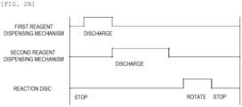
- FIG. 2B is a timing chart showing an operation timing of each mechanism in the first reagent discharge operation.
- a first reagent discharge method is a method in which the second reagent dispensing mechanism 200 starts discharging the second reagent after the first reagent dispensing mechanism 100 finishes discharging the first reagent.
- the reaction disc 1 stops (step S301), and the first reagent dispensing mechanism 100 aspirates the first reagent from the reagent container 10 (step S302). Subsequently, the first reagent dispensing mechanism 100 starts discharging the first reagent, which is aspirated, into the reaction container 2 (step S303).
- step S304 When the first reagent dispensing mechanism 100 finishes discharging the reagent (step S304), the second reagent dispensing mechanism 200 starts discharging the second reagent into the reaction container 2 (step S305).
- step S306 When the second reagent dispensing mechanism 200 finishes discharging the reagent (step S306), the reaction disc 1 rotates (step S307), and when the reaction container 2 is at a measurement position or the like, the reaction disc 1 stops again (step S308).
- the amount of the second reagent is larger than that of the first reagent, so that the first reagent and the second reagent are efficiently mixed by a liquid flow of a large amount of the second reagent that is discharged later.
- a discharge amount of the second reagent is not so large or when a viscosity of the first reagent is extremely high, it is conceivable that the previously discharged first reagent accumulates on a bottom surface of the reaction container 2 and is difficult to flow. In such a case, the reaction container 2 is further stirred by the stirring mechanism 5 at a stirring position.
- FIG. 3A is a flowchart showing a second reagent discharge operation.
- FIG. 3B is a timing chart showing an operation timing of each mechanism in the second reagent discharge operation.
- a second reagent discharge method is a method in which the second reagent dispensing mechanism 200 starts discharging the second reagent before the first reagent dispensing mechanism 100 finishes discharging the first reagent.
- the reaction disc 1 stops (step S401), and the first reagent dispensing mechanism 100 aspirates the first reagent from the reagent container 10 (step S402). Subsequently, the first reagent dispensing mechanism 100 starts discharging the first reagent, which is aspirated, into the reaction container 2 (step S403). Up to this point, the method is the same as the first reagent discharge method.
- the second reagent dispensing mechanism 200 starts discharging the second reagent (step S404). While the second reagent dispensing mechanism 200 is discharging the second reagent, the first reagent dispensing mechanism 100 finishes discharging the reagent first (step S405), and then the second reagent dispensing mechanism 200 finishes discharging the reagent (step S406).
- the reaction disc 1 rotates (step S407), and when the reaction container 2 is at a measurement position or the like, the reaction disc 1 stops again (step S408).
- the second reagent is discharged before the previously discharged first reagent accumulates on the bottom surface of the reaction container 2, and thus a large amount of the second reagent involves a small amount of the first reagent, promoting mixing of the first reagent and the second reagent.
- FIG. 4A is a flowchart showing a third reagent discharge operation.
- FIG. 4B is a timing chart showing an operation timing of each mechanism in the third reagent discharge operation.
- a third reagent discharge method is a method in which the first reagent dispensing mechanism 100 starts and finishes discharging the first reagent while the second reagent dispensing mechanism 200 is discharging the second reagent.
- reaction disc 1 stops (step S501), and the first reagent dispensing mechanism 100 aspirates the first reagent from the reagent container 10 (step S502).
- the second reagent dispensing mechanism 200 starts discharging the second reagent before the first reagent dispensing mechanism 100 starts discharging the first reagent (step S503). Then, while the second reagent dispensing mechanism 200 is discharging the second reagent, the first reagent dispensing mechanism 100 starts discharging the first reagent (step S504). When a predetermined amount of the first reagent is discharged, the first reagent dispensing mechanism 100 finishes discharging the first reagent (step S505). Thereafter, the second reagent dispensing mechanism 200 finishes discharging the second reagent (step S506). When each reagent dispensing mechanism finishes discharging the reagent, the reaction disc 1 rotates (step S507), and when the reaction container 2 is at a measurement position or the like, the reaction disc 1 stops again (step S508).
- the third reagent discharge method a small amount of the first reagent flows into a liquid flow of a large amount of the second reagent, thereby promoting mixing of the first reagent and the second reagent. Therefore, even when a discharge amount of the second reagent is not so large or a viscosity of the first reagent is extremely high, the first reagent and the second reagent can be uniformly mixed.
- a position relationship between the first reagent dispensing mechanism 100 and the second reagent dispensing mechanism 200 when the first reagent and the second reagent are discharged to the stopped common reaction container 2 will be described with reference to FIGS. 5 to 7 .
- the reagent discharge nozzle 14a of the second reagent dispensing mechanism 200 will be described as an example, but the same applies to the reagent discharge nozzle 15a, the reagent discharge nozzle 16a, and the reagent discharge nozzle 17a.
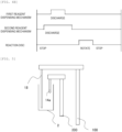
- FIG. 5 is a side view showing the position relationship of the reagent dispensing mechanisms.
- a discharge port of the reagent discharge nozzle 14a of the second reagent dispensing mechanism 200 is located higher than a discharge port of a reagent discharge nozzle 18 of the first reagent dispensing mechanism 100. Therefore, the first reagent discharged from the reagent discharge nozzle 18 of the first reagent dispensing mechanism 100 is hard to adhere to the reagent discharge nozzle 14a of the second reagent dispensing mechanism 200, and the reagent discharge nozzle 14a does not need to be washed as long as the reagent discharge nozzle 14a continues to discharge the same second reagent.
- a liquid surface in the reaction container 2 at a time when the discharge of the second reagent by the second reagent dispensing mechanism 200 ends is higher than the discharge port of the reagent discharge nozzle 18 of the first reagent dispensing mechanism 100. Accordingly, when the first reagent is a concentration reagent and the second reagent is a reagent that is shared with a plurality of concentration reagents, such as a diluent, it is expected that the second reagent will also have an effect of washing an outer wall of the reagent discharge nozzle 18 of the first reagent dispensing mechanism 100.
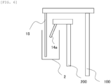
- FIG. 6 is a side view showing another position relationship of the reagent dispensing mechanisms.
- the reagent discharge nozzle 14a of the second reagent dispensing mechanism 200 is inclined toward the reagent discharge nozzle 18 of the first reagent dispensing mechanism 100 with respect to a vertical direction, and the discharge port of the reagent discharge nozzle 14a is open toward the outer wall of the reagent discharge nozzle 18 of the first reagent dispensing mechanism 100.
- a diluent discharged from the reagent discharge nozzle 14a of the second reagent dispensing mechanism 200 directly hits the outer wall of the reagent discharge nozzle 18 of the first reagent dispensing mechanism 100, and a washing effect is further enhanced. Since the second reagent is obliquely discharged with respect to the vertical direction, mixing can be promoted even when the first reagent and the second reagent are difficult to be mixed, such as when an amount of the second reagent discharged to the reaction container 2 is not large and a difference in amount with the first reagent is small, or when a viscosity of the first reagent is high.
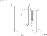
- FIG. 7 is a side view showing still another position relationship of the reagent dispensing mechanisms.
- the discharge port of the reagent discharge nozzle 14a of the second reagent dispensing mechanism 200 is located closer to a side surface of the reaction container 2 than the discharge port of the reagent discharge nozzle 18 of the first reagent dispensing mechanism 100. Therefore, particularly when the reaction container 2 has a round bottom shape, the second reagent flows along a curved surface on an outer diameter side toward an inner diameter side, promoting mixing of the first reagent and the second reagent.
- the second reagent dispensing mechanism 200 includes the temperature adjustment mechanism (not shown). Therefore, even when the first reagent dispensing mechanism 100 does not include a temperature adjustment mechanism, the second reagent to be mixed with the first reagent is adjusted to a predetermined temperature in advance by the temperature adjustment mechanism of the second reagent dispensing mechanism 200, so that the mixed liquid itself can be controlled to a temperature suitable for analysis (for example, 37°C). For example, when the first reagent is kept cool or at room temperature in the reaction disc 1, the second reagent may be adjusted in advance to a temperature higher than the temperature suitable for analysis (for example, 37°C to 40°C).
- the amount of the first reagent discharged by the first reagent dispensing mechanism 100 to the reaction container 2 is smaller than the amount of the second reagent discharged by the second reagent dispensing mechanism 200 into the common reaction container 2, and it is assumed that, for example, the first reagent is a concentration reagent and the second reagent is a diluent. Therefore, even when a temperature of the first reagent is low before the first reagent is discharged, the temperature of the first reagent is likely to increase when mixed with the second reagent.
- the temperature adjustment mechanism may control so as to lower a temperature of the second reagent before discharging when a ratio of the amount of the second reagent to the amount of the first reagent is large, and to raise the temperature of the second reagent before discharging when the ratio of the amount of the second reagent to the amount of the first reagent is small.
- FIG. 8 is a plan view showing a schematic configuration of an automatic analysis device according to a modification of Embodiment 1.
- the first reagent dispensing mechanism 100 can discharge a reagent only at the second reagent discharge position D
- the second reagent dispensing mechanism 200 can discharge a reagent only at the first reagent discharge position B.
- the first reagent dispensing mechanism 100 discharges the first reagent at the second reagent discharge position D
- the second reagent dispensing mechanism 200 discharges the second reagent at the first reagent discharge position B.
- the amount of the second reagent is larger than that of the first reagent, so that the first reagent and the second reagent are efficiently mixed by a liquid flow of a large amount of the second reagent that is discharged later.
- a discharge amount of the second reagent is not so large or when a viscosity of the first reagent is extremely high, a mixed liquid in the reaction container 2 is further stirred by the stirring mechanism 5.
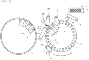
- FIG. 9 is a plan view showing a schematic configuration of an automatic analysis device according to Embodiment 2.
- the automatic analysis device according to the present embodiment further includes a reagent loading position 11. That is, the first reagent dispensing mechanism 100 according to the Embodiment 2 can aspirate the first reagent not only from the reagent disc 9 but also from the reagent loading position 11.
- a plurality of reagent containers 12 or one reagent container 12 may be loaded in the reagent loading position 11.
- the first reagent contained in the reagent container 12 may be different from or the same as the first reagent contained in the reagent container 10 on the reagent disc 9.
- the reagent container 12 placed on the reagent loading position 11 and the reagent container 10 placed on the reagent disc 9 do not need to have the same shape, and may have different shapes depending on an amount of use and a frequency of use.
- the reagent container 10 (reagent container for disc), the reagent container 12 (reagent container for loading position), and another reagent container 12 (another reagent container for loading position) are disposed at different positions on a movement trajectory of the first reagent dispensing mechanism 100, specifically, at the reagent aspirating position H, a reagent aspirating position F, and a reagent aspirating position G.
- the first reagent dispensing mechanism 100 discharges the reagent aspirated from each reagent container into the common reaction container 2 at the first reagent discharge position B and/or the second reagent discharge position D.
- the second reagent dispensing mechanism 200 may dispense the reagent into the stopped common reaction container 2.
- the reaction container 2 which is dispensed with a sample, moves to the second reagent discharge position D.
- the first reagent dispensing mechanism 100 aspirates the first reagent from the reagent container 12 at the reagent aspirating position F and the reagent aspirating position G, and if necessary, the outer wall of the reagent discharge nozzle 18 is washed by the first reagent dispensing mechanism washing mechanism 101 at a predetermined washing position. Further, the first reagent dispensing mechanism 100 aspirates another first reagent from the reagent container 10 at the reagent aspirating position H.
- the first reagent dispensing mechanism 100 discharges each first reagent that is aspirated to the reaction container 2 at the second reagent discharge position D.
- the first reagent dispensing mechanism 100 before the first reagent dispensing mechanism 100 discharges the first reagent that is aspirated from the reagent container 12 into the reaction container 2, the first reagent dispensing mechanism 100 also aspirates the first reagent from the reagent container 10, and discharges the first reagents collectively into the reaction container 2, so that the first reagent can be efficiently dispensed into the reaction container 2.
- the first reagent dispensing mechanism 100 may first aspirate the first reagent at the reagent aspirating position H, and then aspirates the first reagent at the reagent aspirating position F or the reagent aspirating position G.
- the first reagent dispensed by the first reagent dispensing mechanism 100 of the pipetting type for example, the first reagent that needs to be kept cool and the first reagent that is used frequently can be stored separately on the reagent disc 9 and the reagent loading position 11, respectively. That is, when the first reagent contained in the reagent container 12 has a high frequency of use and does not require cooling, the reagent container 12 has a size larger than that of the reagent container 10 and is stored in the reagent loading position 11 that does not have a cooling function.
- the first reagent dispensing mechanism 100 of the pipetting type can further dispense various first reagents.
- the reagent disc 9 stores the first reagent in a refrigerated state and the reagent loading position 11 stores the first reagent at room temperature, but it is also possible to configure the reagent disc 9 so as not to have a cooling function, and for the reagent loading position 11 to have the cooling function.
- FIG. 10 is a plan view showing a schematic configuration of an automatic analysis device according to a modification of Embodiment 2.
- the first reagent dispensing mechanism 100 can discharge a reagent only at the second reagent discharge position D
- the second reagent dispensing mechanism 200 can discharge a reagent only at the first reagent discharge position B.
- various first reagents stored in different reagent containers can be efficiently dispensed into the reaction container 2. As a result, a time required for preparations before analysis can be reduced.
- FIG. 11 is a plan view showing a schematic configuration of an automatic analysis device according to Embodiment 3.
- the reagent container 12 containing the first reagent to be dispensed by the first reagent dispensing mechanism 100 and reagent containers 14 to 17 containing the second reagent to be dispensed by the second reagent dispensing mechanism 200 are provided side by side in the common reagent loading position 13.
- the reagent containers 14 to 17 are connected to the reagent discharge nozzles 14a to 17a of the second reagent dispensing mechanism 200 via reagent transport tubes 14b to 17b, respectively.
- the automatic analysis device since the reagent containers of the reagent dispensing mechanisms are put together, a user can easily dispose or replace the reagent containers.
- the reagent loading position 13 like the reagent disc 9, is located at a front of the automatic analysis device (at least the first reagent dispensing mechanism 100 and the second reagent dispensing mechanism), disposition and replacement of reagent containers can be performed in a space in front of the automatic analysis device, further improving workability.
- Embodiment 1 to Embodiment 3 have been described in detail to facilitate understanding of the invention, and the invention is not necessarily limited to those including all the configurations described above. Further, a part of a configuration of a certain embodiment can also be replaced with a configuration of another embodiment, and a configuration of another embodiment can also be added to a configuration of a certain embodiment. A part of a configuration in each embodiment may also be added to, deleted from, or replaced with another configuration.
Landscapes
- Chemical & Material Sciences (AREA)
- Physics & Mathematics (AREA)
- Health & Medical Sciences (AREA)
- Life Sciences & Earth Sciences (AREA)
- Analytical Chemistry (AREA)
- Biochemistry (AREA)
- General Health & Medical Sciences (AREA)
- General Physics & Mathematics (AREA)
- Immunology (AREA)
- Pathology (AREA)
- Chemical Kinetics & Catalysis (AREA)
- Automatic Analysis And Handling Materials Therefor (AREA)
Abstract
Description
- The present invention relates to an automatic analysis device.
- In an automatic analysis device for automatically analyzing components of a sample (specimen) such as blood, a sample and a reagent are dispensed and mixed, and the obtained mixed liquid is used for measurement. Here, a pipetting type is generally known as a reagent dispensing method. As described in
PTL 1, for example, a dispensing mechanism of a pipetting type aspirates a reagent from a reagent container, then rises, rotates horizontally, and then descends to discharge the reagent into a reaction container. - PTL 1:
JP2011-99681A - The reagent dispensing mechanism of the pipetting type is suitable for dispensing various reagents, but is not suitable for adjusting a temperature of a reagent. When a temperature of a reagent is adjusted in an automatic analysis device adopting a dispensing mechanism of a pipetting type, as described in
PTL 1, it is necessary to incorporate a heater in the dispensing mechanism itself or to temporarily dispense the reagent into another reaction container or the like to raise the temperature for a certain period of time. In the reagent dispensing mechanism of the pipetting type, an amount of reagent that can be dispensed at one time is limited. Therefore, in the reagent dispensing mechanism of the pipetting type, preparations before analysis such as adjusting the temperature of the reagent and dispensing an appropriate amount of reagent tend to take time, and as a result, an analysis time may become long. - The purpose of the invention is to provide an automatic analysis device by which it is possible to shorten analysis time while guaranteeing use of various reagents.
- In order to solve the above problems, this automatic analysis device according to the invention includes: a first reagent dispensing mechanism of a pipetting type that, upon aspirating a reagent, moves to a prescribed location away from the reagent and then discharges the reagent; and a second reagent dispensing mechanism of a dispensing type that supplies a reagent via a flow path connecting an aspirating port to a discharge port for the reagent. The second reagent dispensing mechanism includes a temperature adjustment mechanism that adjusts a temperature of the reagent.
- According to the invention, it is possible to provide an automatic analysis device by which it is possible to shorten analysis time while guaranteeing use of various reagents.
-
- [
FIG. 1] FIG. 1 is a plan view showing a schematic configuration of an automatic analysis device according toEmbodiment 1. - [
FIG. 2A] FIG. 2A is a flowchart showing a first reagent discharge operation. - [
FIG. 2B] FIG. 2B is a timing chart showing an operation timing of each mechanism in the first reagent discharge operation. - [
FIG. 3A] FIG. 3A is a flowchart showing a second reagent discharge operation. - [
FIG. 3B] FIG. 3B is a timing chart showing an operation timing of each mechanism in the second reagent discharge operation. - [
FIG. 4A] FIG. 4A is a flowchart showing a third reagent discharge operation. - [
FIG. 4B] FIG. 4B is a timing chart showing an operation timing of each mechanism in the third reagent discharge operation. - [
FIG. 5] FIG. 5 is a side view showing a position relationship of reagent dispensing mechanisms. - [
FIG. 6] FIG. 6 is a side view showing another position relationship of the reagent dispensing mechanisms. - [
FIG. 7] FIG. 7 is a side view showing still another position relationship of the reagent dispensing mechanisms. - [
FIG. 8] FIG. 8 is a plan view showing a schematic configuration of an automatic analysis device according to a modification ofEmbodiment 1. - [
FIG. 9] FIG. 9 is a plan view showing a schematic configuration of an automatic analysis device according toEmbodiment 2. - [
FIG. 10] FIG. 10 is a plan view showing a schematic configuration of an automatic analysis device according to a modification ofEmbodiment 2. - [
FIG. 11] FIG. 11 is a plan view showing a schematic configuration of an automatic analysis device according toEmbodiment 3. - An embodiment of an automatic analysis device according to the invention will be described with reference to
Embodiment 1 toEmbodiment 3. -
FIG. 1 is a plan view showing a schematic configuration of an automatic analysis device according toEmbodiment 1. As shown inFIG. 1 , the automatic analysis device according to the present embodiment mainly includes areaction disc 1, asample conveyance mechanism 8, asample dispensing mechanism 3, areagent disc 9 including areaction container 2, a firstreagent dispensing mechanism 100, a secondreagent dispensing mechanism 200, and astirring mechanism 5. Although not shown inFIG. 1 , the automatic analysis device according to the present embodiment includes a measurement unit that measures transmitted light and scattered light of a mixed liquid of a sample and a reagent, and a control unit that controls each mechanism. In the present embodiment, an example in which the measurement unit measures transmitted light or scattered light will be described. However, the measurement unit may measure potential, electrical resistance, chemiluminescence, fluorescence, and the like, and is not limited to a measurement method. The measurement unit is not limited to measurement of the mixed liquid contained in thereaction container 2, and the measurement unit may measure the mixed liquid after moving the mixed liquid from thereaction container 2 to the measurement unit using a nozzle, a flow path, or the like for solution transportation. - The
reaction disc 1 includes a plurality ofreaction containers 2 for reacting a sample and a reagent, in a state of being separated from each other at predetermined intervals along a circumferential direction thereof (circumferentially), and rotates in a direction indicated by an arrow Z inFIG. 1 . Thesample conveyance mechanism 8 is provided near thereaction disc 1 and conveys arack 7 on which asample container 6 is placed. The sample dispensing mechanism aspirates the sample contained in thesample container 6 and discharges the sample to thereaction container 2, and is capable of vertical movement and horizontal rotation. Thereagent disc 9 is a storage on which a plurality ofreagent containers 10 containing reagents are placed in a circumferential shape, and is kept cool as necessary. - The first
reagent dispensing mechanism 100 is a mechanism for dispensing the reagent by pipetting type. When the firstreagent dispensing mechanism 100 aspirates the reagent (first reagent) contained in thereagent container 10 on thereagent disc 9, the firstreagent dispensing mechanism 100 rises to separate from the reagent, rotates to a reagent discharge position on thereaction disc 1, and then descends to discharge the reagent to thereaction container 2. When thereagent container 10 to be aspirated is changed and a type of the dispensed first reagent changes, the firstreagent dispensing mechanism 100 is washed by the first reagent dispensingmechanism washing mechanism 101. - On the other hand, the second
reagent dispensing mechanism 200 is a mechanism for dispensing the reagent by a dispensing type, and supplies the reagent (second reagent) through a flow path connected from an aspirating port to a discharge port for the reagent. The discharge port of the secondreagent dispensing mechanism 200 includes a plurality ofreagent discharge nozzles 14a to 17a, each of which discharges the second reagent to thereaction container 2 at the reagent discharge position. Although not shown inFIG. 1 , each of the nozzles is connected via separate reagent transport tubes to an aspirating port of the reagent container loaded in a common reagent loading position, and the second reagent can be sent by an operation of a syringe, a diaphragm pump, or the like. The secondreagent dispensing mechanism 200 may have one reagent discharge nozzle. - The second
reagent dispensing mechanism 200 according to the present embodiment includes a temperature adjustment mechanism (not shown) for adjusting a temperature of the second reagent. The temperature of the second reagent in the secondreagent dispensing mechanism 200 is adjusted in at least one of thereagent discharge nozzles 14a to 17a, a syringe, a reagent transport tube, and other reagent storing units, so that the second reagent is adjusted (heated) in advance to a temperature suitable for analysis before being discharged to thereaction container 2. Therefore, a time required to adjust the temperature of the reagent can be reduced, and as a result, an overall analysis time can be shortened. When thereaction disc 1 has a temperature adjustment mechanism such as a thermostatic bath, the temperature of the reagent in thereaction container 2 after dispensing may also be adjusted. In particular, when an amount of dispensing is large, it is effective to use the temperature adjustment mechanism of the secondreagent dispensing mechanism 200 and the temperature adjustment mechanism of thereaction disc 1 in combination. - In the automatic analysis device according to the present embodiment shown in
FIG. 1 , the firstreagent dispensing mechanism 100 and the secondreagent dispensing mechanism 200 can discharge the reagent to thereaction container 2 at a first reagent discharge position B and a second reagent discharge position D. Therefore, only one dispensing mechanism may discharge the reagent at the first reagent discharge position B, and the other dispensing mechanism may discharge the reagent at the second reagent discharge position D. In the following, an example will be described in which the firstreagent dispensing mechanism 100 discharges the first reagent and the secondreagent dispensing mechanism 200 discharges the second reagent at the first reagent discharge position B. - The
stirring mechanism 5 stirs the sample and the reagent dispensed into thereaction container 2, and is washed by a stirringmechanism washing mechanism 51. Thestirring mechanism 5 is not limited to a contact type using a stirring rod or the like, but may be a non-contact type (ultrasonic wave or the like) that does not require washing. In addition to the above-described mechanisms, the automatic analysis device includes a sample dispensingmechanism washing mechanism 31 that washes thesample dispensing mechanism 3, a second reagent dispensingmechanism washing mechanism 201 that washes the secondreagent dispensing mechanism 200, and a reactioncontainer washing mechanism 4 that washes thereaction container 2. In the reactioncontainer washing mechanism 4, the mixed liquid is discharged from thereaction container 2 for which measurement is ended, and washing water is supplied to wash thereaction container 2. - An analysis operation of the automatic analysis device will be described.
- First, the
sample dispensing mechanism 3 aspirates the sample from thesample container 6 on therack 7 conveyed by thesample conveyance mechanism 8, and discharges the sample to thereaction container 2 at a sample discharge position A. After the sample is dispensed, thesample dispensing mechanism 3 is washed by the sample dispensingmechanism washing mechanism 31. - Next, the
reaction disc 1 rotates, and when thereaction container 2 into which the sample is dispensed is at the first reagent discharge position B, thereaction disc 1 stops. At this time, the firstreagent dispensing mechanism 100 aspirates the first reagent from thereagent container 10 at a reagent aspirating position H, and discharges the first reagent to thereaction container 2 at the first reagent discharge position B. On the other hand, the secondreagent dispensing mechanism 200 discharges the second reagent from any one of thereagent discharge nozzles 14a to 17a into thecommon reaction container 2 at the first reagent discharge position B. - Thereafter, the
reaction disc 1 rotates, and when thereaction container 2 into which the sample and the reagent are dispensed is at a first stirring position C, thereaction disc 1 stops. At this time, thestirring mechanism 5 stirs the sample and the reagent in thereaction container 2. When the sample and the reagent are sufficiently mixed in a process of discharging the reagent from the firstreagent dispensing mechanism 100 and the secondreagent dispensing mechanism 200, stirring by thestirring mechanism 5 can be omitted. - Further, if necessary, the
reaction disc 1 stops when thereaction container 2 is at the second reagent discharge position D, and the firstreagent dispensing mechanism 100 and/or the secondreagent dispensing mechanism 200 dispenses the reagent to thereaction container 2. When the reagent is dispensed into thereaction container 2 at the second reagent discharge position D, when thereaction container 2 is at a second stirring position E, thestirring mechanism 5 stirs the sample and the reagent in thereaction container 2. - When the stirring of the sample and the reagent in the
reaction container 2 is ended, thereaction disc 1 rotates and thereaction container 2 moves to a measurement position. The measurement unit measures transmitted light and scattered light emitted from a light source to thereaction container 2, and transmits a result to the control unit. After the measurement is ended, thereaction container 2 is washed by the reactioncontainer washing mechanism 4 and conveyed to a disposal unit. - Here, among the operations described above, in particular, the operation when the first
reagent dispensing mechanism 100 and the secondreagent dispensing mechanism 200 dispense the reagent to the stoppedcommon reaction container 2 will be described, and three methods will be specifically described. In any of reagent discharge methods described below, it is assumed that an amount of the second reagent that is discharged by the secondreagent dispensing mechanism 200 into thereaction container 2 is larger than an amount of the first reagent that is discharged by the firstreagent dispensing mechanism 100 into thereaction container 2. Therefore, in any of the reagent discharge methods, discharging of the first reagent is ended before discharging of the second reagent. -
FIG. 2A is a flowchart showing a first reagent discharge operation.FIG. 2B is a timing chart showing an operation timing of each mechanism in the first reagent discharge operation. A first reagent discharge method is a method in which the secondreagent dispensing mechanism 200 starts discharging the second reagent after the firstreagent dispensing mechanism 100 finishes discharging the first reagent. - First, when the
reaction container 2 is at a reagent discharge position, thereaction disc 1 stops (step S301), and the firstreagent dispensing mechanism 100 aspirates the first reagent from the reagent container 10 (step S302). Subsequently, the firstreagent dispensing mechanism 100 starts discharging the first reagent, which is aspirated, into the reaction container 2 (step S303). - When the first
reagent dispensing mechanism 100 finishes discharging the reagent (step S304), the secondreagent dispensing mechanism 200 starts discharging the second reagent into the reaction container 2 (step S305). When the secondreagent dispensing mechanism 200 finishes discharging the reagent (step S306), thereaction disc 1 rotates (step S307), and when thereaction container 2 is at a measurement position or the like, thereaction disc 1 stops again (step S308). - As described above, the amount of the second reagent is larger than that of the first reagent, so that the first reagent and the second reagent are efficiently mixed by a liquid flow of a large amount of the second reagent that is discharged later. When a discharge amount of the second reagent is not so large or when a viscosity of the first reagent is extremely high, it is conceivable that the previously discharged first reagent accumulates on a bottom surface of the
reaction container 2 and is difficult to flow. In such a case, thereaction container 2 is further stirred by thestirring mechanism 5 at a stirring position. -
FIG. 3A is a flowchart showing a second reagent discharge operation.FIG. 3B is a timing chart showing an operation timing of each mechanism in the second reagent discharge operation. A second reagent discharge method is a method in which the secondreagent dispensing mechanism 200 starts discharging the second reagent before the firstreagent dispensing mechanism 100 finishes discharging the first reagent. - First, when the
reaction container 2 is at a reagent discharge position, thereaction disc 1 stops (step S401), and the firstreagent dispensing mechanism 100 aspirates the first reagent from the reagent container 10 (step S402). Subsequently, the firstreagent dispensing mechanism 100 starts discharging the first reagent, which is aspirated, into the reaction container 2 (step S403). Up to this point, the method is the same as the first reagent discharge method. - In the second reagent discharge method, while the first
reagent dispensing mechanism 100 is discharging the first reagent, the secondreagent dispensing mechanism 200 starts discharging the second reagent (step S404). While the secondreagent dispensing mechanism 200 is discharging the second reagent, the firstreagent dispensing mechanism 100 finishes discharging the reagent first (step S405), and then the secondreagent dispensing mechanism 200 finishes discharging the reagent (step S406). When each reagent dispensing mechanism finishes discharging the reagent, thereaction disc 1 rotates (step S407), and when thereaction container 2 is at a measurement position or the like, thereaction disc 1 stops again (step S408). - According to the second reagent discharge method, the second reagent is discharged before the previously discharged first reagent accumulates on the bottom surface of the
reaction container 2, and thus a large amount of the second reagent involves a small amount of the first reagent, promoting mixing of the first reagent and the second reagent. -
FIG. 4A is a flowchart showing a third reagent discharge operation.FIG. 4B is a timing chart showing an operation timing of each mechanism in the third reagent discharge operation. A third reagent discharge method is a method in which the firstreagent dispensing mechanism 100 starts and finishes discharging the first reagent while the secondreagent dispensing mechanism 200 is discharging the second reagent. - First, when the
reaction container 2 is at a reagent discharge position, thereaction disc 1 stops (step S501), and the firstreagent dispensing mechanism 100 aspirates the first reagent from the reagent container 10 (step S502). - Next, in the third reagent discharge method, the second
reagent dispensing mechanism 200 starts discharging the second reagent before the firstreagent dispensing mechanism 100 starts discharging the first reagent (step S503). Then, while the secondreagent dispensing mechanism 200 is discharging the second reagent, the firstreagent dispensing mechanism 100 starts discharging the first reagent (step S504). When a predetermined amount of the first reagent is discharged, the firstreagent dispensing mechanism 100 finishes discharging the first reagent (step S505). Thereafter, the secondreagent dispensing mechanism 200 finishes discharging the second reagent (step S506). When each reagent dispensing mechanism finishes discharging the reagent, thereaction disc 1 rotates (step S507), and when thereaction container 2 is at a measurement position or the like, thereaction disc 1 stops again (step S508). - An order of steps S502 and S503 described above may be reversed.
- According to the third reagent discharge method, a small amount of the first reagent flows into a liquid flow of a large amount of the second reagent, thereby promoting mixing of the first reagent and the second reagent. Therefore, even when a discharge amount of the second reagent is not so large or a viscosity of the first reagent is extremely high, the first reagent and the second reagent can be uniformly mixed.
- Next, a position relationship between the first
reagent dispensing mechanism 100 and the secondreagent dispensing mechanism 200 when the first reagent and the second reagent are discharged to the stoppedcommon reaction container 2 will be described with reference toFIGS. 5 to 7 . Here, thereagent discharge nozzle 14a of the secondreagent dispensing mechanism 200 will be described as an example, but the same applies to thereagent discharge nozzle 15a, thereagent discharge nozzle 16a, and thereagent discharge nozzle 17a. -
FIG. 5 is a side view showing the position relationship of the reagent dispensing mechanisms. As shown inFIG. 5 , a discharge port of thereagent discharge nozzle 14a of the secondreagent dispensing mechanism 200 is located higher than a discharge port of areagent discharge nozzle 18 of the firstreagent dispensing mechanism 100. Therefore, the first reagent discharged from thereagent discharge nozzle 18 of the firstreagent dispensing mechanism 100 is hard to adhere to thereagent discharge nozzle 14a of the secondreagent dispensing mechanism 200, and thereagent discharge nozzle 14a does not need to be washed as long as thereagent discharge nozzle 14a continues to discharge the same second reagent. - Further, it is desirable that a liquid surface in the
reaction container 2 at a time when the discharge of the second reagent by the secondreagent dispensing mechanism 200 ends is higher than the discharge port of thereagent discharge nozzle 18 of the firstreagent dispensing mechanism 100. Accordingly, when the first reagent is a concentration reagent and the second reagent is a reagent that is shared with a plurality of concentration reagents, such as a diluent, it is expected that the second reagent will also have an effect of washing an outer wall of thereagent discharge nozzle 18 of the firstreagent dispensing mechanism 100. -
FIG. 6 is a side view showing another position relationship of the reagent dispensing mechanisms. In a case shown inFIG. 6 as well, a similar effect as in a case ofFIG. 5 can be expected. Further, as shown inFIG. 6 , thereagent discharge nozzle 14a of the secondreagent dispensing mechanism 200 is inclined toward thereagent discharge nozzle 18 of the firstreagent dispensing mechanism 100 with respect to a vertical direction, and the discharge port of thereagent discharge nozzle 14a is open toward the outer wall of thereagent discharge nozzle 18 of the firstreagent dispensing mechanism 100. Therefore, a diluent discharged from thereagent discharge nozzle 14a of the secondreagent dispensing mechanism 200 directly hits the outer wall of thereagent discharge nozzle 18 of the firstreagent dispensing mechanism 100, and a washing effect is further enhanced. Since the second reagent is obliquely discharged with respect to the vertical direction, mixing can be promoted even when the first reagent and the second reagent are difficult to be mixed, such as when an amount of the second reagent discharged to thereaction container 2 is not large and a difference in amount with the first reagent is small, or when a viscosity of the first reagent is high. Since a trace amount of the first reagent adhering to and remaining on the discharge port and the outer wall of thereagent discharge nozzle 18 is also washed away by the second reagent, a degree of accuracy of the amount of the first reagent contained in the mixed liquid also increases. -
FIG. 7 is a side view showing still another position relationship of the reagent dispensing mechanisms. In a case shown inFIG. 7 as well, a similar effect as in a case ofFIG. 5 can be expected. Further, in the case shown inFIG. 7 , the discharge port of thereagent discharge nozzle 14a of the secondreagent dispensing mechanism 200 is located closer to a side surface of thereaction container 2 than the discharge port of thereagent discharge nozzle 18 of the firstreagent dispensing mechanism 100. Therefore, particularly when thereaction container 2 has a round bottom shape, the second reagent flows along a curved surface on an outer diameter side toward an inner diameter side, promoting mixing of the first reagent and the second reagent. - As described above, the second
reagent dispensing mechanism 200 includes the temperature adjustment mechanism (not shown). Therefore, even when the firstreagent dispensing mechanism 100 does not include a temperature adjustment mechanism, the second reagent to be mixed with the first reagent is adjusted to a predetermined temperature in advance by the temperature adjustment mechanism of the secondreagent dispensing mechanism 200, so that the mixed liquid itself can be controlled to a temperature suitable for analysis (for example, 37°C). For example, when the first reagent is kept cool or at room temperature in thereaction disc 1, the second reagent may be adjusted in advance to a temperature higher than the temperature suitable for analysis (for example, 37°C to 40°C). - As described above, the amount of the first reagent discharged by the first
reagent dispensing mechanism 100 to thereaction container 2 is smaller than the amount of the second reagent discharged by the secondreagent dispensing mechanism 200 into thecommon reaction container 2, and it is assumed that, for example, the first reagent is a concentration reagent and the second reagent is a diluent. Therefore, even when a temperature of the first reagent is low before the first reagent is discharged, the temperature of the first reagent is likely to increase when mixed with the second reagent. The temperature adjustment mechanism may control so as to lower a temperature of the second reagent before discharging when a ratio of the amount of the second reagent to the amount of the first reagent is large, and to raise the temperature of the second reagent before discharging when the ratio of the amount of the second reagent to the amount of the first reagent is small. -
FIG. 8 is a plan view showing a schematic configuration of an automatic analysis device according to a modification ofEmbodiment 1. As shown inFIG. 8 , in the present modification, the firstreagent dispensing mechanism 100 can discharge a reagent only at the second reagent discharge position D, and the secondreagent dispensing mechanism 200 can discharge a reagent only at the first reagent discharge position B. First, the firstreagent dispensing mechanism 100 discharges the first reagent at the second reagent discharge position D, and then the secondreagent dispensing mechanism 200 discharges the second reagent at the first reagent discharge position B. - In the present modification as well, the amount of the second reagent is larger than that of the first reagent, so that the first reagent and the second reagent are efficiently mixed by a liquid flow of a large amount of the second reagent that is discharged later. When a discharge amount of the second reagent is not so large or when a viscosity of the first reagent is extremely high, a mixed liquid in the
reaction container 2 is further stirred by thestirring mechanism 5. - Even in a case of the present modification, it is possible to dispense a relatively large amount of the second reagent whose temperature is adjusted by the second
reagent dispensing mechanism 200 of a dispensing type while guaranteeing use of various first reagents by the firstreagent dispensing mechanism 100 of a pipetting type. Therefore, according to the present modification, it is also possible to shorten a time required for preparations before analysis such as adjusting a temperature of the reagent and dispensing an appropriate amount of reagent. -
FIG. 9 is a plan view showing a schematic configuration of an automatic analysis device according toEmbodiment 2. As shown inFIG. 9 , unlikeEmbodiment 1, the automatic analysis device according to the present embodiment further includes areagent loading position 11. That is, the firstreagent dispensing mechanism 100 according to theEmbodiment 2 can aspirate the first reagent not only from thereagent disc 9 but also from thereagent loading position 11. A plurality ofreagent containers 12 or onereagent container 12 may be loaded in thereagent loading position 11. The first reagent contained in thereagent container 12 may be different from or the same as the first reagent contained in thereagent container 10 on thereagent disc 9. Further, thereagent container 12 placed on thereagent loading position 11 and thereagent container 10 placed on thereagent disc 9 do not need to have the same shape, and may have different shapes depending on an amount of use and a frequency of use. - In the present embodiment, the reagent container 10 (reagent container for disc), the reagent container 12 (reagent container for loading position), and another reagent container 12 (another reagent container for loading position) are disposed at different positions on a movement trajectory of the first
reagent dispensing mechanism 100, specifically, at the reagent aspirating position H, a reagent aspirating position F, and a reagent aspirating position G. The firstreagent dispensing mechanism 100 discharges the reagent aspirated from each reagent container into thecommon reaction container 2 at the first reagent discharge position B and/or the second reagent discharge position D. In the present embodiment as well, similarly to theEmbodiment 1, not only the firstreagent dispensing mechanism 100 but also the secondreagent dispensing mechanism 200 may dispense the reagent into the stoppedcommon reaction container 2. - Here, a reagent dispensing operation in the present embodiment will be described. First, by rotating and stopping the
reaction disc 1, thereaction container 2, which is dispensed with a sample, moves to the second reagent discharge position D. Next, the firstreagent dispensing mechanism 100 aspirates the first reagent from thereagent container 12 at the reagent aspirating position F and the reagent aspirating position G, and if necessary, the outer wall of thereagent discharge nozzle 18 is washed by the first reagent dispensingmechanism washing mechanism 101 at a predetermined washing position. Further, the firstreagent dispensing mechanism 100 aspirates another first reagent from thereagent container 10 at the reagent aspirating position H. Thereafter, the firstreagent dispensing mechanism 100 discharges each first reagent that is aspirated to thereaction container 2 at the second reagent discharge position D. Thus, in the present embodiment, before the firstreagent dispensing mechanism 100 discharges the first reagent that is aspirated from thereagent container 12 into thereaction container 2, the firstreagent dispensing mechanism 100 also aspirates the first reagent from thereagent container 10, and discharges the first reagents collectively into thereaction container 2, so that the first reagent can be efficiently dispensed into thereaction container 2. The firstreagent dispensing mechanism 100 may first aspirate the first reagent at the reagent aspirating position H, and then aspirates the first reagent at the reagent aspirating position F or the reagent aspirating position G. - In the automatic analysis device according to the present embodiment, as the first reagent dispensed by the first
reagent dispensing mechanism 100 of the pipetting type, for example, the first reagent that needs to be kept cool and the first reagent that is used frequently can be stored separately on thereagent disc 9 and thereagent loading position 11, respectively. That is, when the first reagent contained in thereagent container 12 has a high frequency of use and does not require cooling, thereagent container 12 has a size larger than that of thereagent container 10 and is stored in thereagent loading position 11 that does not have a cooling function. Thus, according to the present embodiment, the firstreagent dispensing mechanism 100 of the pipetting type can further dispense various first reagents. In the present embodiment, it is assumed that thereagent disc 9 stores the first reagent in a refrigerated state and thereagent loading position 11 stores the first reagent at room temperature, but it is also possible to configure thereagent disc 9 so as not to have a cooling function, and for thereagent loading position 11 to have the cooling function. -
FIG. 10 is a plan view showing a schematic configuration of an automatic analysis device according to a modification ofEmbodiment 2. As shown inFIG. 10 , in the present modification, the firstreagent dispensing mechanism 100 can discharge a reagent only at the second reagent discharge position D, and the secondreagent dispensing mechanism 200 can discharge a reagent only at the first reagent discharge position B. According to the automatic analysis device in the present modification, various first reagents stored in different reagent containers can be efficiently dispensed into thereaction container 2. As a result, a time required for preparations before analysis can be reduced. -
FIG. 11 is a plan view showing a schematic configuration of an automatic analysis device according toEmbodiment 3. As shown inFIG. 11 , in the automatic analysis device according to the present embodiment, thereagent container 12 containing the first reagent to be dispensed by the firstreagent dispensing mechanism 100 andreagent containers 14 to 17 containing the second reagent to be dispensed by the secondreagent dispensing mechanism 200 are provided side by side in the commonreagent loading position 13. Thereagent containers 14 to 17 are connected to thereagent discharge nozzles 14a to 17a of the secondreagent dispensing mechanism 200 viareagent transport tubes 14b to 17b, respectively. - In the automatic analysis device according to the present embodiment, since the reagent containers of the reagent dispensing mechanisms are put together, a user can easily dispose or replace the reagent containers. In particular, since the
reagent loading position 13, like thereagent disc 9, is located at a front of the automatic analysis device (at least the firstreagent dispensing mechanism 100 and the second reagent dispensing mechanism), disposition and replacement of reagent containers can be performed in a space in front of the automatic analysis device, further improving workability. - The above-described
Embodiment 1 toEmbodiment 3 have been described in detail to facilitate understanding of the invention, and the invention is not necessarily limited to those including all the configurations described above. Further, a part of a configuration of a certain embodiment can also be replaced with a configuration of another embodiment, and a configuration of another embodiment can also be added to a configuration of a certain embodiment. A part of a configuration in each embodiment may also be added to, deleted from, or replaced with another configuration. -
- 1: reaction disc
- 2: reaction container
- 3: sample dispensing mechanism
- 4: reaction container washing mechanism
- 5: stirring mechanism
- 6: sample container
- 7: rack
- 8: sample conveyance mechanism
- 9: reagent disc
- 10: reagent container
- 11: reagent loading position
- 12: reagent container
- 13: reagent loading position
- 14 to 17: reagent container
- 14a to 17a: reagent discharge nozzle
- 14b to 17b: reagent transport tube
- 18: reagent discharge nozzle
- 31: sample dispensing mechanism washing mechanism
- 51: stirring mechanism washing mechanism
- 100: first reagent dispensing mechanism
- 101: first reagent dispensing mechanism washing mechanism
- 200: second reagent dispensing mechanism
- 201: second reagent dispensing mechanism washing mechanism
Claims (15)
- An automatic analysis device comprising:a first reagent dispensing mechanism of a pipetting type that, upon aspirating a reagent, moves to a prescribed location away from the reagent and then discharges the reagent; anda second reagent dispensing mechanism of a dispensing type that supplies a reagent via a flow path connecting an aspirating port to a discharge port for the reagent, whereinthe second reagent dispensing mechanism includes a temperature adjustment mechanism that adjusts a temperature of the reagent.
- The automatic analysis device according to claim 1, wherein
an amount of second reagent discharged by the second reagent dispensing mechanism into a common reaction container is larger than an amount of first reagent discharged by the first reagent dispensing mechanism into the reaction container. - The automatic analysis device according to claim 2, wherein
the first reagent dispensing mechanism discharges the first reagent, and the second reagent dispensing mechanism discharges the second reagent to the stopped common reaction container. - The automatic analysis device according to claim 3, wherein
the second reagent dispensing mechanism starts discharging the second reagent after the first reagent dispensing mechanism starts discharging the first reagent. - The automatic analysis device according to claim 4, wherein
the second reagent dispensing mechanism starts discharging the second reagent before the first reagent dispensing mechanism finishes discharging the first reagent. - The automatic analysis device according to claim 4, wherein
the second reagent dispensing mechanism finishes discharging the second reagent after the first reagent dispensing mechanism finishes discharging the first reagent. - The automatic analysis device according to claim 3, wherein
the first reagent dispensing mechanism starts and finishes discharging the first reagent while the second reagent dispensing mechanism is discharging the second reagent. - The automatic analysis device according to claim 3, wherein
the discharge port of the second reagent dispensing mechanism is located higher than a discharge port of the first reagent dispensing mechanism. - The automatic analysis device according to claim 8, whereinthe first reagent is a concentration reagent, and the second reagent is a diluent, andthe diluent discharged from the second reagent dispensing mechanism hits an outer wall of a nozzle of the first reagent dispensing mechanism.
- The automatic analysis device according to claim 9, wherein
the discharge port of the second reagent dispensing mechanism is open toward the outer wall of the nozzle of the first reagent dispensing mechanism. - The automatic analysis device according to claim 3, wherein
the discharge port of the second reagent dispensing mechanism is located closer to a side surface of the reaction container than a discharge port of the first reagent dispensing mechanism. - The automatic analysis device according to claim 1, whereinreagent containers are disposed at different positions on a movement trajectory of the first reagent dispensing mechanism, andthe first reagent dispensing mechanism discharges a reagent aspirated from each reagent container into a common reaction container.
- The automatic analysis device according to claim 12, wherein
before discharging a reagent aspirated from a predetermined reagent container, the first reagent dispensing mechanism also aspirates a reagent from another reagent container, and collectively discharges the reagents into the reaction container. - The automatic analysis device according to claim 1, wherein
a reagent container that contains a first reagent to be dispensed by the first reagent dispensing mechanism and a reagent container that contains a second reagent to be dispensed by the second reagent dispensing mechanism are provided side by side in a common reagent loading position. - The automatic analysis device according to claim 14, wherein
the reagent loading position is located in front of the first reagent dispensing mechanism and the second reagent dispensing mechanism.
Applications Claiming Priority (2)
| Application Number | Priority Date | Filing Date | Title |
|---|---|---|---|
| JP2022051586 | 2022-03-28 | ||
| PCT/JP2023/003293 WO2023188795A1 (en) | 2022-03-28 | 2023-02-01 | Automatic analysis device |
Publications (2)
| Publication Number | Publication Date |
|---|---|
| EP4502619A1 true EP4502619A1 (en) | 2025-02-05 |
| EP4502619A4 EP4502619A4 (en) | 2026-07-01 |
Family
ID=88200830
Family Applications (1)
| Application Number | Title | Priority Date | Filing Date |
|---|---|---|---|
| EP23778831.0A Pending EP4502619A4 (en) | 2022-03-28 | 2023-02-01 | AUTOMATIC ANALYSIS DEVICE |
Country Status (5)
| Country | Link |
|---|---|
| US (1) | US20250231208A1 (en) |
| EP (1) | EP4502619A4 (en) |
| JP (1) | JP7766787B2 (en) |
| CN (1) | CN118922724A (en) |
| WO (1) | WO2023188795A1 (en) |
Family Cites Families (9)
| Publication number | Priority date | Publication date | Assignee | Title |
|---|---|---|---|---|
| JPH0422870A (en) * | 1990-05-18 | 1992-01-27 | Nittec Co Ltd | Automatic analyzing apparatus |
| JP3228745B2 (en) * | 1992-03-27 | 2001-11-12 | アボツト・ラボラトリーズ | Low birefringence plastic cuvette |
| JP2011033426A (en) * | 2009-07-31 | 2011-02-17 | Hitachi High-Technologies Corp | Automatic analyzer and method of controlling the same |
| CN104871007A (en) * | 2012-12-26 | 2015-08-26 | 株式会社日立高新技术 | Automatic analyzer |
| EP3747545B1 (en) * | 2013-07-25 | 2024-09-18 | Siemens Healthcare Diagnostics Inc. | Reagent dispensers, dispensing apparatus, and methods |
| CN107209195B (en) * | 2015-02-25 | 2018-10-16 | 株式会社日立高新技术 | Automatic analysis device |
| EP3588100B1 (en) * | 2017-02-24 | 2021-12-29 | Hitachi High-Tech Corporation | Automated analyzer |
| JP6814171B2 (en) * | 2018-03-19 | 2021-01-13 | 株式会社日立ハイテク | Automatic analyzer |
| EP4071486A4 (en) * | 2019-12-05 | 2024-04-03 | Hitachi High-Tech Corporation | Automatic analysis device |
-
2023
- 2023-02-01 WO PCT/JP2023/003293 patent/WO2023188795A1/en not_active Ceased
- 2023-02-01 EP EP23778831.0A patent/EP4502619A4/en active Pending
- 2023-02-01 US US18/848,611 patent/US20250231208A1/en active Pending
- 2023-02-01 CN CN202380029918.6A patent/CN118922724A/en active Pending
- 2023-02-01 JP JP2024511330A patent/JP7766787B2/en active Active
Also Published As
| Publication number | Publication date |
|---|---|
| JPWO2023188795A1 (en) | 2023-10-05 |
| EP4502619A4 (en) | 2026-07-01 |
| US20250231208A1 (en) | 2025-07-17 |
| JP7766787B2 (en) | 2025-11-10 |
| CN118922724A (en) | 2024-11-08 |
| WO2023188795A1 (en) | 2023-10-05 |
Similar Documents
| Publication | Publication Date | Title |
|---|---|---|
| JP2023022294A (en) | Automatic analysis device and automatic analysis method | |
| JP6549329B2 (en) | Automatic analyzer | |
| WO2016009764A1 (en) | Liquid stirring method | |
| JP6242260B2 (en) | Automatic analyzer and automatic analysis method | |
| US11808671B2 (en) | Automatic analysis device | |
| EP3517973A1 (en) | Automated analysis device | |
| JP2011220928A (en) | Autoanalyzer | |
| JP6153759B2 (en) | Automatic analyzer | |
| EP4012419A1 (en) | Liquid dispensing device | |
| JPS6366466A (en) | Discrete type automatic analyzer | |
| JP2015132521A (en) | solution preparation system | |
| US20250231208A1 (en) | Automatic Analysis Device | |
| EP3578994A1 (en) | Automatic analyzer | |
| JP2015215367A (en) | Automatic analyzer | |
| US11906406B2 (en) | Automatic analyzer and analysis method | |
| JP6745407B2 (en) | Automatic analyzer | |
| JP7495867B2 (en) | Automated Analysis Equipment | |
| JP2019148572A (en) | Automatic analyzer and dispensation method | |
| CN114829945B (en) | Automatic analyzer and control program product for automatic analyzer | |
| US11879902B2 (en) | Test method and dispensing device | |
| JP2014228318A (en) | Automatic analyzer and automatic analysis method | |
| EP4700392A1 (en) | Automatic analysis device and automatic analysis method | |
| EP4660633A1 (en) | Automatic analysis device | |
| JP2005291727A (en) | Biochemical analyzer | |
| JP2014219422A (en) | Autoanalyzer |
Legal Events
| Date | Code | Title | Description |
|---|---|---|---|
| STAA | Information on the status of an ep patent application or granted ep patent |
Free format text: STATUS: THE INTERNATIONAL PUBLICATION HAS BEEN MADE |
|
| PUAI | Public reference made under article 153(3) epc to a published international application that has entered the european phase |
Free format text: ORIGINAL CODE: 0009012 |
|
| STAA | Information on the status of an ep patent application or granted ep patent |
Free format text: STATUS: REQUEST FOR EXAMINATION WAS MADE |
|
| 17P | Request for examination filed |
Effective date: 20241028 |
|
| AK | Designated contracting states |
Kind code of ref document: A1 Designated state(s): AL AT BE BG CH CY CZ DE DK EE ES FI FR GB GR HR HU IE IS IT LI LT LU LV MC ME MK MT NL NO PL PT RO RS SE SI SK SM TR |
|
| DAV | Request for validation of the european patent (deleted) | ||
| DAX | Request for extension of the european patent (deleted) | ||
| RIC1 | Information provided on ipc code assigned before grant |
Ipc: G01N 35/10 20060101AFI20260303BHEP |
|
| A4 | Supplementary search report drawn up and despatched |
Effective date: 20260601 |
|
| RIC1 | Information provided on ipc code assigned before grant |
Ipc: G01N 35/10 20060101AFI20260526BHEP |