EP4502565A1 - Nitrogen pressurization system for leak testing of gas pipes for engine, and ship including same - Google Patents
Nitrogen pressurization system for leak testing of gas pipes for engine, and ship including same Download PDFInfo
- Publication number
- EP4502565A1 EP4502565A1 EP23709307.5A EP23709307A EP4502565A1 EP 4502565 A1 EP4502565 A1 EP 4502565A1 EP 23709307 A EP23709307 A EP 23709307A EP 4502565 A1 EP4502565 A1 EP 4502565A1
- Authority
- EP
- European Patent Office
- Prior art keywords
- nitrogen
- air
- engine
- gas pipeline
- valve
- Prior art date
- Legal status (The legal status is an assumption and is not a legal conclusion. Google has not performed a legal analysis and makes no representation as to the accuracy of the status listed.)
- Pending
Links
Images

Classifications
-
- G—PHYSICS
- G01—MEASURING; TESTING
- G01M—TESTING STATIC OR DYNAMIC BALANCE OF MACHINES OR STRUCTURES; TESTING OF STRUCTURES OR APPARATUS, NOT OTHERWISE PROVIDED FOR
- G01M3/00—Investigating fluid-tightness of structures
- G01M3/02—Investigating fluid-tightness of structures by using fluid or vacuum
- G01M3/04—Investigating fluid-tightness of structures by using fluid or vacuum by detecting the presence of fluid at the leakage point
- G01M3/20—Investigating fluid-tightness of structures by using fluid or vacuum by detecting the presence of fluid at the leakage point using special tracer materials, e.g. dye, fluorescent material, radioactive material
- G01M3/22—Investigating fluid-tightness of structures by using fluid or vacuum by detecting the presence of fluid at the leakage point using special tracer materials, e.g. dye, fluorescent material, radioactive material for pipes, cables or tubes; for pipe joints or seals; for valves; for welds; for containers, e.g. radiators
-
- F—MECHANICAL ENGINEERING; LIGHTING; HEATING; WEAPONS; BLASTING
- F17—STORING OR DISTRIBUTING GASES OR LIQUIDS
- F17C—VESSELS FOR CONTAINING OR STORING COMPRESSED, LIQUEFIED OR SOLIDIFIED GASES; FIXED-CAPACITY GAS-HOLDERS; FILLING VESSELS WITH, OR DISCHARGING FROM VESSELS, COMPRESSED, LIQUEFIED, OR SOLIDIFIED GASES
- F17C9/00—Methods or apparatus for discharging liquefied or solidified gases from vessels not under pressure
-
- B—PERFORMING OPERATIONS; TRANSPORTING
- B63—SHIPS OR OTHER WATERBORNE VESSELS; RELATED EQUIPMENT
- B63B—SHIPS OR OTHER WATERBORNE VESSELS; EQUIPMENT FOR SHIPPING
- B63B11/00—Interior subdivision of hulls
-
- B—PERFORMING OPERATIONS; TRANSPORTING
- B63—SHIPS OR OTHER WATERBORNE VESSELS; RELATED EQUIPMENT
- B63H—MARINE PROPULSION OR STEERING
- B63H21/00—Use of propulsion power plant or units on vessels
- B63H21/38—Apparatus or methods specially adapted for use on marine vessels, for handling power plant or unit liquids, e.g. lubricants, coolants, fuels or the like
-
- F—MECHANICAL ENGINEERING; LIGHTING; HEATING; WEAPONS; BLASTING
- F02—COMBUSTION ENGINES; HOT-GAS OR COMBUSTION-PRODUCT ENGINE PLANTS
- F02D—CONTROLLING COMBUSTION ENGINES
- F02D19/00—Controlling engines characterised by their use of non-liquid fuels, pluralities of fuels, or non-fuel substances added to the combustible mixtures
- F02D19/02—Controlling engines characterised by their use of non-liquid fuels, pluralities of fuels, or non-fuel substances added to the combustible mixtures peculiar to engines working with gaseous fuels
- F02D19/025—Failure diagnosis or prevention; Safety measures; Testing
-
- F—MECHANICAL ENGINEERING; LIGHTING; HEATING; WEAPONS; BLASTING
- F02—COMBUSTION ENGINES; HOT-GAS OR COMBUSTION-PRODUCT ENGINE PLANTS
- F02D—CONTROLLING COMBUSTION ENGINES
- F02D41/00—Electrical control of supply of combustible mixture or its constituents
- F02D41/0025—Controlling engines characterised by use of non-liquid fuels, pluralities of fuels, or non-fuel substances added to the combustible mixtures
- F02D41/0027—Controlling engines characterised by use of non-liquid fuels, pluralities of fuels, or non-fuel substances added to the combustible mixtures the fuel being gaseous
-
- F—MECHANICAL ENGINEERING; LIGHTING; HEATING; WEAPONS; BLASTING
- F02—COMBUSTION ENGINES; HOT-GAS OR COMBUSTION-PRODUCT ENGINE PLANTS
- F02D—CONTROLLING COMBUSTION ENGINES
- F02D41/00—Electrical control of supply of combustible mixture or its constituents
- F02D41/22—Safety or indicating devices for abnormal conditions
-
- F—MECHANICAL ENGINEERING; LIGHTING; HEATING; WEAPONS; BLASTING
- F02—COMBUSTION ENGINES; HOT-GAS OR COMBUSTION-PRODUCT ENGINE PLANTS
- F02M—SUPPLYING COMBUSTION ENGINES IN GENERAL WITH COMBUSTIBLE MIXTURES OR CONSTITUENTS THEREOF
- F02M21/00—Apparatus for supplying engines with non-liquid fuels, e.g. gaseous fuels stored in liquid form
- F02M21/02—Apparatus for supplying engines with non-liquid fuels, e.g. gaseous fuels stored in liquid form for gaseous fuels
- F02M21/0218—Details on the gaseous fuel supply system, e.g. tanks, valves, pipes, pumps, rails, injectors or mixers
- F02M21/0293—Safety devices; Fail-safe measures
-
- F—MECHANICAL ENGINEERING; LIGHTING; HEATING; WEAPONS; BLASTING
- F17—STORING OR DISTRIBUTING GASES OR LIQUIDS
- F17C—VESSELS FOR CONTAINING OR STORING COMPRESSED, LIQUEFIED OR SOLIDIFIED GASES; FIXED-CAPACITY GAS-HOLDERS; FILLING VESSELS WITH, OR DISCHARGING FROM VESSELS, COMPRESSED, LIQUEFIED, OR SOLIDIFIED GASES
- F17C7/00—Methods or apparatus for discharging liquefied, solidified, or compressed gases from pressure vessels, not covered by another subclass
-
- G—PHYSICS
- G01—MEASURING; TESTING
- G01M—TESTING STATIC OR DYNAMIC BALANCE OF MACHINES OR STRUCTURES; TESTING OF STRUCTURES OR APPARATUS, NOT OTHERWISE PROVIDED FOR
- G01M3/00—Investigating fluid-tightness of structures
- G01M3/02—Investigating fluid-tightness of structures by using fluid or vacuum
- G01M3/025—Details with respect to the testing of engines or engine parts
-
- G—PHYSICS
- G01—MEASURING; TESTING
- G01M—TESTING STATIC OR DYNAMIC BALANCE OF MACHINES OR STRUCTURES; TESTING OF STRUCTURES OR APPARATUS, NOT OTHERWISE PROVIDED FOR
- G01M3/00—Investigating fluid-tightness of structures
- G01M3/02—Investigating fluid-tightness of structures by using fluid or vacuum
- G01M3/26—Investigating fluid-tightness of structures by using fluid or vacuum by measuring rate of loss or gain of fluid, e.g. by pressure-responsive devices, by flow detectors
- G01M3/28—Investigating fluid-tightness of structures by using fluid or vacuum by measuring rate of loss or gain of fluid, e.g. by pressure-responsive devices, by flow detectors for pipes, cables or tubes; for pipe joints or seals; for valves ; for welds
-
- F—MECHANICAL ENGINEERING; LIGHTING; HEATING; WEAPONS; BLASTING
- F02—COMBUSTION ENGINES; HOT-GAS OR COMBUSTION-PRODUCT ENGINE PLANTS
- F02D—CONTROLLING COMBUSTION ENGINES
- F02D41/00—Electrical control of supply of combustible mixture or its constituents
- F02D41/22—Safety or indicating devices for abnormal conditions
- F02D2041/224—Diagnosis of the fuel system
- F02D2041/225—Leakage detection
-
- F—MECHANICAL ENGINEERING; LIGHTING; HEATING; WEAPONS; BLASTING
- F02—COMBUSTION ENGINES; HOT-GAS OR COMBUSTION-PRODUCT ENGINE PLANTS
- F02N—STARTING OF COMBUSTION ENGINES; STARTING AIDS FOR SUCH ENGINES, NOT OTHERWISE PROVIDED FOR
- F02N9/00—Starting of engines by supplying auxiliary pressure fluid to their working chambers
- F02N9/04—Starting of engines by supplying auxiliary pressure fluid to their working chambers the pressure fluid being generated otherwise, e.g. by compressing air
-
- F—MECHANICAL ENGINEERING; LIGHTING; HEATING; WEAPONS; BLASTING
- F17—STORING OR DISTRIBUTING GASES OR LIQUIDS
- F17C—VESSELS FOR CONTAINING OR STORING COMPRESSED, LIQUEFIED OR SOLIDIFIED GASES; FIXED-CAPACITY GAS-HOLDERS; FILLING VESSELS WITH, OR DISCHARGING FROM VESSELS, COMPRESSED, LIQUEFIED, OR SOLIDIFIED GASES
- F17C2205/00—Vessel construction, in particular mounting arrangements, attachments or identifications means
- F17C2205/03—Fluid connections, filters, valves, closure means or other attachments
- F17C2205/0302—Fittings, valves, filters, or components in connection with the gas storage device
- F17C2205/0323—Valves
-
- F—MECHANICAL ENGINEERING; LIGHTING; HEATING; WEAPONS; BLASTING
- F17—STORING OR DISTRIBUTING GASES OR LIQUIDS
- F17C—VESSELS FOR CONTAINING OR STORING COMPRESSED, LIQUEFIED OR SOLIDIFIED GASES; FIXED-CAPACITY GAS-HOLDERS; FILLING VESSELS WITH, OR DISCHARGING FROM VESSELS, COMPRESSED, LIQUEFIED, OR SOLIDIFIED GASES
- F17C2205/00—Vessel construction, in particular mounting arrangements, attachments or identifications means
- F17C2205/03—Fluid connections, filters, valves, closure means or other attachments
- F17C2205/0302—Fittings, valves, filters, or components in connection with the gas storage device
- F17C2205/0352—Pipes
-
- F—MECHANICAL ENGINEERING; LIGHTING; HEATING; WEAPONS; BLASTING
- F17—STORING OR DISTRIBUTING GASES OR LIQUIDS
- F17C—VESSELS FOR CONTAINING OR STORING COMPRESSED, LIQUEFIED OR SOLIDIFIED GASES; FIXED-CAPACITY GAS-HOLDERS; FILLING VESSELS WITH, OR DISCHARGING FROM VESSELS, COMPRESSED, LIQUEFIED, OR SOLIDIFIED GASES
- F17C2221/00—Handled fluid, in particular type of fluid
- F17C2221/01—Pure fluids
- F17C2221/014—Nitrogen
-
- F—MECHANICAL ENGINEERING; LIGHTING; HEATING; WEAPONS; BLASTING
- F17—STORING OR DISTRIBUTING GASES OR LIQUIDS
- F17C—VESSELS FOR CONTAINING OR STORING COMPRESSED, LIQUEFIED OR SOLIDIFIED GASES; FIXED-CAPACITY GAS-HOLDERS; FILLING VESSELS WITH, OR DISCHARGING FROM VESSELS, COMPRESSED, LIQUEFIED, OR SOLIDIFIED GASES
- F17C2221/00—Handled fluid, in particular type of fluid
- F17C2221/03—Mixtures
- F17C2221/031—Air
-
- F—MECHANICAL ENGINEERING; LIGHTING; HEATING; WEAPONS; BLASTING
- F17—STORING OR DISTRIBUTING GASES OR LIQUIDS
- F17C—VESSELS FOR CONTAINING OR STORING COMPRESSED, LIQUEFIED OR SOLIDIFIED GASES; FIXED-CAPACITY GAS-HOLDERS; FILLING VESSELS WITH, OR DISCHARGING FROM VESSELS, COMPRESSED, LIQUEFIED, OR SOLIDIFIED GASES
- F17C2227/00—Transfer of fluids, i.e. method or means for transferring the fluid; Heat exchange with the fluid
- F17C2227/01—Propulsion of the fluid
- F17C2227/0128—Propulsion of the fluid with pumps or compressors
- F17C2227/0157—Compressors
-
- F—MECHANICAL ENGINEERING; LIGHTING; HEATING; WEAPONS; BLASTING
- F17—STORING OR DISTRIBUTING GASES OR LIQUIDS
- F17C—VESSELS FOR CONTAINING OR STORING COMPRESSED, LIQUEFIED OR SOLIDIFIED GASES; FIXED-CAPACITY GAS-HOLDERS; FILLING VESSELS WITH, OR DISCHARGING FROM VESSELS, COMPRESSED, LIQUEFIED, OR SOLIDIFIED GASES
- F17C2227/00—Transfer of fluids, i.e. method or means for transferring the fluid; Heat exchange with the fluid
- F17C2227/01—Propulsion of the fluid
- F17C2227/0128—Propulsion of the fluid with pumps or compressors
- F17C2227/0171—Arrangement
- F17C2227/0185—Arrangement comprising several pumps or compressors
-
- F—MECHANICAL ENGINEERING; LIGHTING; HEATING; WEAPONS; BLASTING
- F17—STORING OR DISTRIBUTING GASES OR LIQUIDS
- F17C—VESSELS FOR CONTAINING OR STORING COMPRESSED, LIQUEFIED OR SOLIDIFIED GASES; FIXED-CAPACITY GAS-HOLDERS; FILLING VESSELS WITH, OR DISCHARGING FROM VESSELS, COMPRESSED, LIQUEFIED, OR SOLIDIFIED GASES
- F17C2265/00—Effects achieved by gas storage or gas handling
- F17C2265/06—Fluid distribution
- F17C2265/066—Fluid distribution for feeding engines for propulsion
-
- F—MECHANICAL ENGINEERING; LIGHTING; HEATING; WEAPONS; BLASTING
- F17—STORING OR DISTRIBUTING GASES OR LIQUIDS
- F17C—VESSELS FOR CONTAINING OR STORING COMPRESSED, LIQUEFIED OR SOLIDIFIED GASES; FIXED-CAPACITY GAS-HOLDERS; FILLING VESSELS WITH, OR DISCHARGING FROM VESSELS, COMPRESSED, LIQUEFIED, OR SOLIDIFIED GASES
- F17C2270/00—Applications
- F17C2270/01—Applications for fluid transport or storage
- F17C2270/0102—Applications for fluid transport or storage on or in the water
- F17C2270/0105—Ships
Definitions
- the present invention relates to a nitrogen compression system for a leakage test on a gas pipeline used for an engine and a vessel including the same, and more particularly, to a nitrogen compression system for a leakage test on a gas pipeline used for fuel gas applied to a vessel engine and a vessel including the same.
- a ME-GI (high-pressure dual fuel propulsion) engine uses fuel gas which is compressed at high pressure of approximately 300 bar.
- a leakage test is performed for a gas pipeline to secure stability of the gas pipeline and then, fuel gas is applied to the ME-GI (high-pressure dual fuel propulsion) engine.
- the ME-GA (low-pressure dual fuel propulsion) engine uses fuel gas at low pressure of 10 through 15 bar and thereby, pressure of the fuel gas in the ME-GA engine is significantly lower than that of in the ME-GI engine.
- a leakage test for a gas pipeline is performed by using nitrogen (N2) in such a way that nitrogen of approximately 6 bar generated from a nitrogen generator included in a vessel is compressed in a separate compressor at high pressure of approximately 300 bar.
- N2 nitrogen
- a leakage test for a gas pipeline is performed after nitrogen of approximately 6 bar generated from a nitrogen generator included in a vessel is compressed in a separate compressor at low pressure of approximately 15 bar.
- Such a compressor is expensive and has low capacity so that compression time of about 4 hours is needed. Accordingly, the time required to test a leakage of a gas pipeline is increased.
- the present invention provides a nitrogen compression system for a leakage test on a gas pipeline used for an engine by which the time required for the leakage test may be reduced at a low cost, and a vessel including the same.
- a nitrogen compression system for a leakage test on a gas pipeline used for an engine includes: a nitrogen generator which is installed on a hull and generates nitrogen; a nitrogen storage tank which stores the nitrogen generated from the nitrogen generator; an air compressor which generates compressed air used to support starting of an engine for propelling the hull and supplies the compressed air to the engine; an air supplier which supplies air to the air compressor; and a first diverter valve which is installed on a first diverter pipeline connecting the air supplier, the nitrogen storage tank, and the air compressor and is controlled to supply any one of air and nitrogen to the air compressor.
- compressed nitrogen compressed by the air compressor may be used to purge a gas pipeline connected to the engine.
- an air storage tank which stores the compressed air generated from the air compressor
- a second diverter valve which is installed on a second diverter pipeline connecting the air compressor to the air storage tank and is controlled to supply the compressed air to the air storage tank or to supply the compressed nitrogen to the gas pipeline, may be further included.
- a first nitrogen decompression valve which is installed on the first diverter pipeline and reduces pressure of the nitrogen supplied from the nitrogen storage tank to be supplied to the air compressor, may be further included.
- an initial purging valve interposed between the second diverter valve and the gas pipeline may be further included.
- the second diverter valve and the initial purging valve may be controlled to discharge the compressed air to the outside.
- asecond nitrogen decompression valve which is installed on the gas pipeline disposed at the back end of the initial purging valve and reduces pressure of the compressed nitrogen to be supplied to the gas pipeline, may be further included.
- a nitrogen purging valve which is installed on a nitrogen supply pipeline connecting the nitrogen storage tank to the gas pipeline and supplies the nitrogen stored in the nitrogen storage tank to the gas pipeline, may be further included.
- a vessel including a nitrogen compression system for a leakage test on a gas pipeline used for an engine includes: a hull; an engine room comprising an engine for propelling the hull; and a fuel supplying room including a fuel supplying system for supplying fuel gas to the engine, wherein the engine room further includes: a nitrogen compression system for a leakage test on a gas pipeline of the fuel supplying system and wherein the nitrogen compression system includes: a nitrogen generator which is installed in the engine room and generates nitrogen; a nitrogen storage tank which stores the nitrogen generated from the nitrogen generator; an air compressor which generates compressed air used to support starting of an engine and supplies the compressed air to the engine; an air supplier which supplies air to the air compressor; and a first diverter valve which is installed on a first diverter pipeline connecting the air supplier, the nitrogen storage tank, and the air compressor and is controlled to supply any one of air and nitrogen to the air compressor.
- compressed nitrogen compressed by the air compressor may be used to purge a gas pipeline.
- the nitrogen compression system for a leakage test may further include an air storage tank which stores the compressed air generated from the air compressor; and a second diverter valve which is installed on a second diverter pipeline connecting the air compressor to the air storage tank and is controlled to supply the compressed air to the air storage tank or to supply the compressed nitrogen to the gas pipeline.
- the nitrogen compression system for a leakage test may further include a first nitrogen decompression valve which is installed on the first diverter pipeline and reduces pressure of the nitrogen supplied from the nitrogen storage tank to be supplied to the air compressor.
- the nitrogen compression system for a leakage test may further include an initial purging valve interposed between the second diverter valve and the gas pipeline.
- the second diverter valve and the initial purging valve may be controlled to discharge the compressed air to the outside.
- the nitrogen compression system for a leakage test may further include a second nitrogen decompression valve which is installed on the gas pipeline disposed at the back end of the initial purging valve and reduces pressure of the compressed nitrogen to be supplied to the gas pipeline.
- the nitrogen compression system for a leakage test may further include a nitrogen purging valve which is installed on a nitrogen supply pipeline connecting the nitrogen storage tank to the gas pipeline and supplies the nitrogen stored in the nitrogen storage tank to the gas pipeline.
- the gas pipeline may include: a main gas pipeline which connects the fuel supplying system to the engine; a first gas pipeline which connects the initial purging valve to the engine and supplies compressed nitrogen used to perform a leakage test before the engine starts to the engine; and a second gas pipeline which connects the first gas pipeline to the main gas pipeline.
- the engine may include a ME-GA (low-pressure dual fuel propulsion) engine.
- ME-GA low-pressure dual fuel propulsion
- the air compressor which supplies compressed air to support starting of the engine to the engine is used to compress nitrogen and thereby, compressed nitrogen is generated. Then, the generated compressed nitrogen is used to perform a leakage test on the gas pipeline. Accordingly, a high-priced compressor for generating compressed nitrogen is not separately needed and thereby, a leakage test may be performed at a low cost.
- the air compressor which supplies compressed air used to support starting of the engine to the engine has a capacity greater by 10 times than that of a separate compressor and thereby, the time required for the leakage test on the gas pipeline may be reduced.
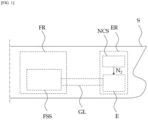
- FIG. 1 schematically illustrates a vessel including a nitrogen compression system for a leakage test on a gas pipeline used for an engine according to an embodiment of the present invention.
- the vessel including a nitrogen compression system NCS for a leakage test on a gas pipeline used for an engine includes a hull S, an engine room ER, and fuel supplying room FR including a fuel supplying system FSS for supplying fuel gas to an engine E.
- the hull S may include various hulls such as a container hull and a liquefied gas hull.
- the engine room ER may include the engine E for propelling the hull S and the nitrogen (N2) compression system NCS used for a leakage test.
- the engine E may be the ME-GA (low-pressure dual fuel propulsion) engine which uses fuel gas at low pressure of 10 through 15 bar.
- the nitrogen (N2) compression system NCS used for a leakage test may perform a leakage test on a gas pipeline GL in such a way that nitrogen N2 for a leakage test of the gas pipeline GL is compressed to generate compressed nitrogen and then, the generated compressed nitrogen is supplied to the gas pipeline GL of the fuel supplying system FSS.
- the fuel supplying room FR may include the fuel supplying system FSS which supplies fuel gas to the engine E.
- FIG. 2 schematically illustrates the nitrogen compression system NCS for a leakage test on a gas pipeline used for an engine according to an embodiment of the present invention.
- the nitrogen compression system NCS for a leakage test on a gas pipeline used for an engine includes a nitrogen generator 100, a nitrogen storage tank 200, an air compressor 300, an air supplier 400, an air storage tank 500, a first diverter valve DV1, a second diverter valve DV2, an initial purging valve IPV, a first nitrogen decompression valve RV1, and a second nitrogen decompression valve RV2.
- the nitrogen generator 100 is installed in the engine room ER included in the hull S and may generate nitrogen N2.
- the nitrogen storage tank 200 adjacent to the nitrogen generator 100 is installed in the engine room ER and may store nitrogen generated from the nitrogen generator 100. Nitrogen stored in the nitrogen storage tank 200 may have pressure of approximately 6 bar.
- the air compressor 300 uses air supplied from the air supplier 400 to generate compressed air which helps in starting and controlling the engine E.
- the compressed air generated from the air compressor 300 is stored in the air storage tank 500 and then, may be supplied to the engine E through a compressed air pipeline CAL.
- the compressed air may have pressure of approximately 30 bar.
- the compressed air may be supplied to a dual circulating pipeline DCL through an engine connecting pipeline ECL which connects the compressed air pipeline CAL to the dual circulating pipeline DCL of the engine E.
- An air decompression unit ARU and a flow switch FS may be installed on the engine connecting pipeline ECL.
- the air decompression unit ARU may supply circulating air to the dual circulating pipeline DCL of the engine E, wherein the circulating air is made by compressing and drying compressed air or compressed nitrogen of 30 bar into approximately 0.5 bar.
- the flow switch FS may identify whether the circulating air passing through the air decompression unit ARU is properly supplied to the dual circulating pipeline DCL of the engine E. When the circulating air is not flowed into the dual circulating pipeline DCL of the engine E, operation of the engine E is stopped.
- the air supplier 400 may supply air to the air compressor 300.
- the air supplier 400 may absorbs an atmosphere and may receive air.
- the air storage tank 500 may store compressed air generated from the air compressor 300.
- the compressed air stored in the air storage tank 500 is supplied to the engine E to assist starting and controlling of the engine E.
- An amount of the compressed air stored in the air storage tank 500 may be equivalent to an amount that enables the engine to start more than 12 times.
- the first diverter valve DV1 may be installed on a first diverter pipeline DL1 which connects the air supplier 400, nitrogen storage tank 200, and the air compressor 300.
- a first diverter valve DV1 may be a 3-way valve.
- the first diverter pipeline DL1 may include a (1-1)th diverter pipeline DL11, a (1-2)th diverter pipeline DL12, and a (1-3)th diverter pipeline DL13, wherein the (1-1)th diverter pipeline DL11 connects the air supplier 400 to the first diverter valve DV1, the (1-2)th diverter pipeline DL12 connects the nitrogen storage tank 200 to the first diverter valve DV1, and the (1-3)th diverter pipeline DL13 connects the first diverter valve DV1 to the air compressor 300.
- any one of air and nitrogen may be supplied to the air compressor 300.
- the first diverter valve DV1 In an operation mode when the engine E is operated, the first diverter valve DV1 is controlled to connect the diverter pipeline DL11 to the (1-3)th diverter pipeline DL13. Accordingly, air may be supplied to the air compressor 300 from the air supplier 400 and thereby, compressed air may be generated. In addition, in a still mode when the engine E is stopped, the first diverter valve DV1 is controlled to connect the (1-2)th diverter pipeline DL12 to the (1-3)th diverter pipeline DL13. Accordingly, nitrogen may be supplied to the air compressor 300 from the nitrogen storage tank 200 and thereby, compressed nitrogen may be generated.
- the second diverter valve DV2 may be installed on a second diverter pipeline DL2 which connects the air compressor 300 to the air storage tank 500.
- a second diverter valve DV2 may be a 3-way valve.
- the second diverter pipeline DL2 may include a (2-1)th diverter pipeline DL21, a (2-2)th diverter pipeline DL22, and a (2-3)th diverter pipeline DL23, wherein the (2-1)th diverter pipeline DL21 connects the air compressor 300 to the second diverter valve DV2, the 2-2)th diverter pipeline DL22 connects the second diverter valve DV2 to the air storage tank 500, and the diverter pipeline DL23 connects the second diverter valve DV2 to the initial purging valve IPV.
- compressed air generated from the air compressor 300 may be supplied to the air storage tank 500 or compressed nitrogen generated from the air compressor 300 may be supplied to the gas pipeline GL.
- the second diverter valve DV2 In an operation mode when the engine E is operated, the second diverter valve DV2 is controlled to connect the (2-1)th diverter pipeline DL21 to (2-2)th diverter pipeline DL22. Accordingly, compressed air generated from the air compressor 300 may be supplied to the air storage tank 500 and thereby, may be supplied to the dual circulating pipeline DCL of the engine E. In addition, in a still mode when the engine E is stopped, the second diverter valve DV2 is controlled to connect the (2-1)th diverter pipeline DL21 to the (2-3)th diverter pipeline DL23. Accordingly, compressed nitrogen generated from the air compressor 300 may be supplied to the gas pipeline GL. Here, a leakage test may be performed on the compressed nitrogen supplied to the gas pipeline GL by purging the gas pipeline GL.
- the gas pipeline GL may include a main gas pipeline MGL, a first gas pipeline GL1, and a second gas pipeline GL2.
- the main gas pipeline MGL may connect the fuel supplying system FSS to the engine E and may supply fuel gas to the engine E from the fuel supplying system FSS.
- a gas valve train GVT, a main gas valve MGV, and a main venting valve MBV may be installed on the main gas pipeline MGL.
- the gas valve train GVT may control supply pressure of fuel gas supplied to the engine E.
- the gas valve train GVT may vent fuel gas from the main gas pipeline MGL or purge the main gas pipeline MGL with compressed air.
- the main gas valve MGV may be installed at the front end of the gas valve train GVT and may block fuel gas supplied to the engine E in case of emergency.
- the main venting valve MBV may vent or purge fuel gas of the main gas pipeline MGL to the outside.
- the first gas pipeline GL1 may connect the initial purging valve IPV to the engine E.
- the first gas pipeline GL1 may supply compressed nitrogen to the engine E, wherein the compressed nitrogen is used to perform a leakage test before the engine E starts.
- a first nitrogen purging block PB1 may be installed on the first gas pipeline GL1. In a still mode when the engine E is stopped, the first nitrogen purging block PB1 may be in a valve group which supplies compressed nitrogen to the first gas pipeline GL1 and purges the first gas pipeline GL1.
- the first nitrogen purging block PB1 may include a first dual control valve DCV1 and a first venting valve VV1, wherein the first dual control valve DCV1 prevents fuel gas to flow backward into the first gas pipeline GL1 and the first venting valve VV1 interposed between the first dual control valves DCV1 vents leakage gas to the outside.
- the second gas pipeline GL2 may connect the first gas pipeline GL1 to the main gas pipeline MGL.
- a second nitrogen purging block PB2 may be installed on the second gas pipeline GL2.
- the second nitrogen purging block PB2 may be in a valve group which supplies compressed nitrogen to the second gas pipeline GL2 disposed at the front end of the gas valve train GVT to vent, purge, and perform a leakage test on the second gas pipeline GL2.
- the second nitrogen purging block PB2 may include a second dual control valve DCV2 and a second venting valve VV2, wherein the second dual control valve DCV2 prevents fuel gas to flow backward into the second gas pipeline GL2 and the second venting valve VV2 interposed between the second dual control valves DCV2 vents leakage gas to the outside.
- the initial purging valve IPV may be interposed between the second diverter valve DV2 and the first gas pipeline GL1. That is, the initial purging valve IPV may be a 3-way valve which is connected to the (2-3)th diverter pipeline DL23, an initial purging pipeline IPL, and the first gas pipeline GL1.
- the second diverter valve DV2 and the initial purging valve IPV may be controlled to discharge compressed air to the outside through the initial purging pipeline IPL for a predetermined time.
- the initial purging pipeline IPL may be connected to the dual circulating pipeline DCL of the engine E through the engine connecting pipeline ECL. Accordingly, compressed air remaining in the (2-1)th diverter pipeline DL21 and the (2-3)th diverter pipeline DL23 at the beginning may be supplied to the dual circulating pipeline DCL of the engine E through the initial purging pipeline IPL and thereby, a function of the air compressor 300 may be improved. Also, compressed nitrogen may be supplied to the dual circulating pipeline DCL of the engine E through the initial purging pipeline IPL and thereby, a function of the air compressor 300 may be improved.
- the second diverter valve DV2 and the initial purging valve IPV may be controlled to discharge compressed nitrogen to the outside through the initial purging pipeline IPL for a predetermined time.
- the first nitrogen decompression valve RV1 may be installed on the (1-2)th diverter pipeline DL12 of the first diverter pipeline DL1.
- the first nitrogen decompression valve RV1 may reduce pressure of nitrogen supplied from the nitrogen storage tank 200 to the air compressor 300 from 6 bar to atmospheric pressure to be supplied to the air compressor 300.
- the second nitrogen decompression valve RV2 may be installed on the gas pipeline GL disposed at the back end of the initial purging valve IPV.
- the second nitrogen decompression valve RV2 may reduce pressure of compressed nitrogen from 30 bar to 15 bar to be supplied to gas pipelines.
- a nitrogen purging valve NPV may be installed on a nitrogen supply pipeline NSL which connects the nitrogen storage tank 200 to the gas pipeline GL.
- the nitrogen purging valve NPV may supply nitrogen at pressure of 6 bar stored in the nitrogen storage tank 200 to the gas pipeline GL and may purge the gas pipeline GL.
- the air compressor 300 which supplies compressed air to support starting of the engine E, the first diverter valve DV1, and the second diverter valve DV2 are used to compress nitrogen and thereby, compressed nitrogen is generated. Then, the generated compressed nitrogen is used to perform a leakage test on the gas pipeline GL. Accordingly, a high-priced compressor for generating compressed nitrogen is not separately needed and thereby, a leakage test may be performed at a low cost.
- the air compressor 300 which supplies compressed air used to support starting of the engine E to the engine E has a capacity greater by 10 times than that of a separate compressor and thereby, the time required for the leakage test on the gas pipeline GL may be reduced.
- the nitrogen generator 100, the nitrogen storage tank 200, the air compressor 300, the air supplier 400, and the air storage tank 500 are disposed in the engine room ER and thereby, the nitrogen compression system for a leakage test connected to the engine E may be easily formed and arranged.
Landscapes
- Engineering & Computer Science (AREA)
- Mechanical Engineering (AREA)
- Chemical & Material Sciences (AREA)
- Combustion & Propulsion (AREA)
- General Engineering & Computer Science (AREA)
- Physics & Mathematics (AREA)
- General Physics & Mathematics (AREA)
- Ocean & Marine Engineering (AREA)
- Biomedical Technology (AREA)
- Health & Medical Sciences (AREA)
- Chemical Kinetics & Catalysis (AREA)
- General Chemical & Material Sciences (AREA)
- Oil, Petroleum & Natural Gas (AREA)
- Examining Or Testing Airtightness (AREA)
Abstract
Description
- The present invention relates to a nitrogen compression system for a leakage test on a gas pipeline used for an engine and a vessel including the same, and more particularly, to a nitrogen compression system for a leakage test on a gas pipeline used for fuel gas applied to a vessel engine and a vessel including the same.
- In general, a ME-GI (high-pressure dual fuel propulsion) engine uses fuel gas which is compressed at high pressure of approximately 300 bar. In this regard, a leakage test is performed for a gas pipeline to secure stability of the gas pipeline and then, fuel gas is applied to the ME-GI (high-pressure dual fuel propulsion) engine.
- Recently, there is an attempt on applying a ME-GA (low-pressure dual fuel propulsion) engine as a dual fuel propulsion engine. The ME-GA (low-pressure dual fuel propulsion) engine uses fuel gas at low pressure of 10 through 15 bar and thereby, pressure of the fuel gas in the ME-GA engine is significantly lower than that of in the ME-GI engine.
- In the ME-GI (high-pressure dual fuel propulsion) engine, a leakage test for a gas pipeline is performed by using nitrogen (N2) in such a way that nitrogen of approximately 6 bar generated from a nitrogen generator included in a vessel is compressed in a separate compressor at high pressure of approximately 300 bar. Also, in the ME-GA (low-pressure dual fuel propulsion) engine, a leakage test for a gas pipeline is performed after nitrogen of approximately 6 bar generated from a nitrogen generator included in a vessel is compressed in a separate compressor at low pressure of approximately 15 bar. Such a compressor is expensive and has low capacity so that compression time of about 4 hours is needed. Accordingly, the time required to test a leakage of a gas pipeline is increased.
- The present invention provides a nitrogen compression system for a leakage test on a gas pipeline used for an engine by which the time required for the leakage test may be reduced at a low cost, and a vessel including the same.
- A nitrogen compression system for a leakage test on a gas pipeline used for an engine according to an aspect of the present invention includes: a nitrogen generator which is installed on a hull and generates nitrogen; a nitrogen storage tank which stores the nitrogen generated from the nitrogen generator; an air compressor which generates compressed air used to support starting of an engine for propelling the hull and supplies the compressed air to the engine; an air supplier which supplies air to the air compressor; and a first diverter valve which is installed on a first diverter pipeline connecting the air supplier, the nitrogen storage tank, and the air compressor and is controlled to supply any one of air and nitrogen to the air compressor.
- Here, when the first diverter valve is controlled to supply nitrogen to the air compressor, compressed nitrogen compressed by the air compressor may be used to purge a gas pipeline connected to the engine.
- At this time, an air storage tank, which stores the compressed air generated from the air compressor, and a second diverter valve, which is installed on a second diverter pipeline connecting the air compressor to the air storage tank and is controlled to supply the compressed air to the air storage tank or to supply the compressed nitrogen to the gas pipeline, may be further included.
- Also, a first nitrogen decompression valve, which is installed on the first diverter pipeline and reduces pressure of the nitrogen supplied from the nitrogen storage tank to be supplied to the air compressor, may be further included.
- Also, an initial purging valve interposed between the second diverter valve and the gas pipeline may be further included.
- Here, when the first diverter valve is controlled to supply the nitrogen to the air compressor, the second diverter valve and the initial purging valve may be controlled to discharge the compressed air to the outside.
- Also, asecond nitrogen decompression valve, which is installed on the gas pipeline disposed at the back end of the initial purging valve and reduces pressure of the compressed nitrogen to be supplied to the gas pipeline, may be further included.
- Also, a nitrogen purging valve, which is installed on a nitrogen supply pipeline connecting the nitrogen storage tank to the gas pipeline and supplies the nitrogen stored in the nitrogen storage tank to the gas pipeline, may be further included.
- On the other hand, a vessel including a nitrogen compression system for a leakage test on a gas pipeline used for an engine according to another aspect of the present invention includes: a hull; an engine room comprising an engine for propelling the hull; and a fuel supplying room including a fuel supplying system for supplying fuel gas to the engine, wherein the engine room further includes: a nitrogen compression system for a leakage test on a gas pipeline of the fuel supplying system and wherein the nitrogen compression system includes: a nitrogen generator which is installed in the engine room and generates nitrogen; a nitrogen storage tank which stores the nitrogen generated from the nitrogen generator; an air compressor which generates compressed air used to support starting of an engine and supplies the compressed air to the engine; an air supplier which supplies air to the air compressor; and a first diverter valve which is installed on a first diverter pipeline connecting the air supplier, the nitrogen storage tank, and the air compressor and is controlled to supply any one of air and nitrogen to the air compressor.
- Here, when the first diverter valve is controlled to supply nitrogen to the air compressor, compressed nitrogen compressed by the air compressor may be used to purge a gas pipeline.
- At this time, the nitrogen compression system for a leakage test may further include an air storage tank which stores the compressed air generated from the air compressor; and a second diverter valve which is installed on a second diverter pipeline connecting the air compressor to the air storage tank and is controlled to supply the compressed air to the air storage tank or to supply the compressed nitrogen to the gas pipeline.
- Also, the nitrogen compression system for a leakage test may further include a first nitrogen decompression valve which is installed on the first diverter pipeline and reduces pressure of the nitrogen supplied from the nitrogen storage tank to be supplied to the air compressor.
- Also, the nitrogen compression system for a leakage test may further include an initial purging valve interposed between the second diverter valve and the gas pipeline.
- Here, when the first diverter valve is controlled to supply the nitrogen to the air compressor, the second diverter valve and the initial purging valve may be controlled to discharge the compressed air to the outside.
- Also, the nitrogen compression system for a leakage test may further include a second nitrogen decompression valve which is installed on the gas pipeline disposed at the back end of the initial purging valve and reduces pressure of the compressed nitrogen to be supplied to the gas pipeline.
- Also, the nitrogen compression system for a leakage test may further include a nitrogen purging valve which is installed on a nitrogen supply pipeline connecting the nitrogen storage tank to the gas pipeline and supplies the nitrogen stored in the nitrogen storage tank to the gas pipeline.
- Also, the gas pipeline may include: a main gas pipeline which connects the fuel supplying system to the engine; a first gas pipeline which connects the initial purging valve to the engine and supplies compressed nitrogen used to perform a leakage test before the engine starts to the engine; and a second gas pipeline which connects the first gas pipeline to the main gas pipeline.
- On the other hand, the engine may include a ME-GA (low-pressure dual fuel propulsion) engine.
- In the nitrogen compression system for a leakage test on a gas pipeline used for an engine and a vessel including the same according to an embodiment of the present invention, the air compressor which supplies compressed air to support starting of the engine to the engine is used to compress nitrogen and thereby, compressed nitrogen is generated. Then, the generated compressed nitrogen is used to perform a leakage test on the gas pipeline. Accordingly, a high-priced compressor for generating compressed nitrogen is not separately needed and thereby, a leakage test may be performed at a low cost.
- Also, the air compressor which supplies compressed air used to support starting of the engine to the engine has a capacity greater by 10 times than that of a separate compressor and thereby, the time required for the leakage test on the gas pipeline may be reduced.
-
-
FIG. 1 schematically illustrates a vessel including a nitrogen compression system for a leakage test on a gas pipeline used for an engine according to an embodiment of the present invention; and -
FIG. 2 schematically illustrates a nitrogen compression system for a leakage test on a gas pipeline used for an engine according to an embodiment of the present invention. - [Mode for Invention] Hereinafter, embodiments of the present invention will be described more fully with reference to the accompanying drawings so as to be easily implemented by one of ordinary skill in the art. The present invention may be embodied in many different forms and should not be construed as being limited to the embodiments set forth herein.
-
FIG. 1 schematically illustrates a vessel including a nitrogen compression system for a leakage test on a gas pipeline used for an engine according to an embodiment of the present invention. - As illustrated in
FIG. 1 , the vessel including a nitrogen compression system NCS for a leakage test on a gas pipeline used for an engine according to an embodiment of the present invention includes a hull S, an engine room ER, and fuel supplying room FR including a fuel supplying system FSS for supplying fuel gas to an engine E. - The hull S may include various hulls such as a container hull and a liquefied gas hull.
- The engine room ER may include the engine E for propelling the hull S and the nitrogen (N2) compression system NCS used for a leakage test. The engine E may be the ME-GA (low-pressure dual fuel propulsion) engine which uses fuel gas at low pressure of 10 through 15 bar. The nitrogen (N2) compression system NCS used for a leakage test may perform a leakage test on a gas pipeline GL in such a way that nitrogen N2 for a leakage test of the gas pipeline GL is compressed to generate compressed nitrogen and then, the generated compressed nitrogen is supplied to the gas pipeline GL of the fuel supplying system FSS.
- The fuel supplying room FR may include the fuel supplying system FSS which supplies fuel gas to the engine E.
- Hereinafter, the nitrogen compression system NCS for a leakage test on a gas pipeline used for an engine according to an embodiment of the present invention will be described in more detail.
-
FIG. 2 schematically illustrates the nitrogen compression system NCS for a leakage test on a gas pipeline used for an engine according to an embodiment of the present invention. - As illustrated in
FIG. 2 , the nitrogen compression system NCS for a leakage test on a gas pipeline used for an engine according to an embodiment of the present invention includes anitrogen generator 100, anitrogen storage tank 200, anair compressor 300, anair supplier 400, anair storage tank 500, a first diverter valve DV1, a second diverter valve DV2, an initial purging valve IPV, a first nitrogen decompression valve RV1, and a second nitrogen decompression valve RV2. - The
nitrogen generator 100 is installed in the engine room ER included in the hull S and may generate nitrogen N2. - The
nitrogen storage tank 200 adjacent to thenitrogen generator 100 is installed in the engine room ER and may store nitrogen generated from thenitrogen generator 100. Nitrogen stored in thenitrogen storage tank 200 may have pressure of approximately 6 bar. - The
air compressor 300 uses air supplied from theair supplier 400 to generate compressed air which helps in starting and controlling the engine E. The compressed air generated from theair compressor 300 is stored in theair storage tank 500 and then, may be supplied to the engine E through a compressed air pipeline CAL. The compressed air may have pressure of approximately 30 bar. Also, the compressed air may be supplied to a dual circulating pipeline DCL through an engine connecting pipeline ECL which connects the compressed air pipeline CAL to the dual circulating pipeline DCL of the engine E. An air decompression unit ARU and a flow switch FS may be installed on the engine connecting pipeline ECL. The air decompression unit ARU may supply circulating air to the dual circulating pipeline DCL of the engine E, wherein the circulating air is made by compressing and drying compressed air or compressed nitrogen of 30 bar into approximately 0.5 bar. The flow switch FS may identify whether the circulating air passing through the air decompression unit ARU is properly supplied to the dual circulating pipeline DCL of the engine E. When the circulating air is not flowed into the dual circulating pipeline DCL of the engine E, operation of the engine E is stopped. - The
air supplier 400 may supply air to theair compressor 300. Theair supplier 400 may absorbs an atmosphere and may receive air. - The
air storage tank 500 may store compressed air generated from theair compressor 300. The compressed air stored in theair storage tank 500 is supplied to the engine E to assist starting and controlling of the engine E. An amount of the compressed air stored in theair storage tank 500 may be equivalent to an amount that enables the engine to start more than 12 times. - The first diverter valve DV1 may be installed on a first diverter pipeline DL1 which connects the
air supplier 400,nitrogen storage tank 200, and theair compressor 300. Such a first diverter valve DV1 may be a 3-way valve. The first diverter pipeline DL1 may include a (1-1)th diverter pipeline DL11, a (1-2)th diverter pipeline DL12, and a (1-3)th diverter pipeline DL13, wherein the (1-1)th diverter pipeline DL11 connects theair supplier 400 to the first diverter valve DV1, the (1-2)th diverter pipeline DL12 connects thenitrogen storage tank 200 to the first diverter valve DV1, and the (1-3)th diverter pipeline DL13 connects the first diverter valve DV1 to theair compressor 300. - As the first diverter valve DV1 is controlled, any one of air and nitrogen may be supplied to the
air compressor 300. - In an operation mode when the engine E is operated, the first diverter valve DV1 is controlled to connect the diverter pipeline DL11 to the (1-3)th diverter pipeline DL13. Accordingly, air may be supplied to the
air compressor 300 from theair supplier 400 and thereby, compressed air may be generated. In addition, in a still mode when the engine E is stopped, the first diverter valve DV1 is controlled to connect the (1-2)th diverter pipeline DL12 to the (1-3)th diverter pipeline DL13. Accordingly, nitrogen may be supplied to theair compressor 300 from thenitrogen storage tank 200 and thereby, compressed nitrogen may be generated. - The second diverter valve DV2 may be installed on a second diverter pipeline DL2 which connects the
air compressor 300 to theair storage tank 500. Such a second diverter valve DV2 may be a 3-way valve. The second diverter pipeline DL2 may include a (2-1)th diverter pipeline DL21, a (2-2)th diverter pipeline DL22, and a (2-3)th diverter pipeline DL23, wherein the (2-1)th diverter pipeline DL21 connects theair compressor 300 to the second diverter valve DV2, the 2-2)th diverter pipeline DL22 connects the second diverter valve DV2 to theair storage tank 500, and the diverter pipeline DL23 connects the second diverter valve DV2 to the initial purging valve IPV. - As the second diverter valve DV2 is controlled, compressed air generated from the
air compressor 300 may be supplied to theair storage tank 500 or compressed nitrogen generated from theair compressor 300 may be supplied to the gas pipeline GL. - In an operation mode when the engine E is operated, the second diverter valve DV2 is controlled to connect the (2-1)th diverter pipeline DL21 to (2-2)th diverter pipeline DL22. Accordingly, compressed air generated from the
air compressor 300 may be supplied to theair storage tank 500 and thereby, may be supplied to the dual circulating pipeline DCL of the engine E. In addition, in a still mode when the engine E is stopped, the second diverter valve DV2 is controlled to connect the (2-1)th diverter pipeline DL21 to the (2-3)th diverter pipeline DL23. Accordingly, compressed nitrogen generated from theair compressor 300 may be supplied to the gas pipeline GL. Here, a leakage test may be performed on the compressed nitrogen supplied to the gas pipeline GL by purging the gas pipeline GL. The gas pipeline GL may include a main gas pipeline MGL, a first gas pipeline GL1, and a second gas pipeline GL2. - The main gas pipeline MGL may connect the fuel supplying system FSS to the engine E and may supply fuel gas to the engine E from the fuel supplying system FSS. A gas valve train GVT, a main gas valve MGV, and a main venting valve MBV may be installed on the main gas pipeline MGL. The gas valve train GVT may control supply pressure of fuel gas supplied to the engine E. Also, while in a gas trip, the gas valve train GVT may vent fuel gas from the main gas pipeline MGL or purge the main gas pipeline MGL with compressed air. The main gas valve MGV may be installed at the front end of the gas valve train GVT and may block fuel gas supplied to the engine E in case of emergency. The main venting valve MBV may vent or purge fuel gas of the main gas pipeline MGL to the outside.
- The first gas pipeline GL1 may connect the initial purging valve IPV to the engine E. The first gas pipeline GL1 may supply compressed nitrogen to the engine E, wherein the compressed nitrogen is used to perform a leakage test before the engine E starts. A first nitrogen purging block PB1 may be installed on the first gas pipeline GL1. In a still mode when the engine E is stopped, the first nitrogen purging block PB1 may be in a valve group which supplies compressed nitrogen to the first gas pipeline GL1 and purges the first gas pipeline GL1. The first nitrogen purging block PB1 may include a first dual control valve DCV1 and a first venting valve VV1, wherein the first dual control valve DCV1 prevents fuel gas to flow backward into the first gas pipeline GL1 and the first venting valve VV1 interposed between the first dual control valves DCV1 vents leakage gas to the outside.
- The second gas pipeline GL2 may connect the first gas pipeline GL1 to the main gas pipeline MGL. A second nitrogen purging block PB2 may be installed on the second gas pipeline GL2. The second nitrogen purging block PB2 may be in a valve group which supplies compressed nitrogen to the second gas pipeline GL2 disposed at the front end of the gas valve train GVT to vent, purge, and perform a leakage test on the second gas pipeline GL2. The second nitrogen purging block PB2 may include a second dual control valve DCV2 and a second venting valve VV2, wherein the second dual control valve DCV2 prevents fuel gas to flow backward into the second gas pipeline GL2 and the second venting valve VV2 interposed between the second dual control valves DCV2 vents leakage gas to the outside.
- The initial purging valve IPV may be interposed between the second diverter valve DV2 and the first gas pipeline GL1. That is, the initial purging valve IPV may be a 3-way valve which is connected to the (2-3)th diverter pipeline DL23, an initial purging pipeline IPL, and the first gas pipeline GL1.
- When the first diverter valve DV1 is controlled to supply nitrogen to the
air compressor 300, the second diverter valve DV2 and the initial purging valve IPV may be controlled to discharge compressed air to the outside through the initial purging pipeline IPL for a predetermined time. The initial purging pipeline IPL may be connected to the dual circulating pipeline DCL of the engine E through the engine connecting pipeline ECL. Accordingly, compressed air remaining in the (2-1)th diverter pipeline DL21 and the (2-3)th diverter pipeline DL23 at the beginning may be supplied to the dual circulating pipeline DCL of the engine E through the initial purging pipeline IPL and thereby, a function of theair compressor 300 may be improved. Also, compressed nitrogen may be supplied to the dual circulating pipeline DCL of the engine E through the initial purging pipeline IPL and thereby, a function of theair compressor 300 may be improved. - When the first diverter valve DV1 is controlled to supply air to the
air compressor 300, the second diverter valve DV2 and the initial purging valve IPV may be controlled to discharge compressed nitrogen to the outside through the initial purging pipeline IPL for a predetermined time. - The first nitrogen decompression valve RV1 may be installed on the (1-2)th diverter pipeline DL12 of the first diverter pipeline DL1. When pressure of gas acceptable to the
air compressor 300 is fixed and theair compressor 300 is not able to receive nitrogen at pressure of 6 bar from thenitrogen storage tank 200, the first nitrogen decompression valve RV1 may reduce pressure of nitrogen supplied from thenitrogen storage tank 200 to theair compressor 300 from 6 bar to atmospheric pressure to be supplied to theair compressor 300. - The second nitrogen decompression valve RV2 may be installed on the gas pipeline GL disposed at the back end of the initial purging valve IPV. The second nitrogen decompression valve RV2 may reduce pressure of compressed nitrogen from 30 bar to 15 bar to be supplied to gas pipelines.
- A nitrogen purging valve NPV may be installed on a nitrogen supply pipeline NSL which connects the
nitrogen storage tank 200 to the gas pipeline GL. In a still mode when the engine E is stopped or a manual mode, the nitrogen purging valve NPV may supply nitrogen at pressure of 6 bar stored in thenitrogen storage tank 200 to the gas pipeline GL and may purge the gas pipeline GL. - In the nitrogen compression system for a leakage test on a gas pipeline used for an engine according to an embodiment of the present invention described above, the
air compressor 300 which supplies compressed air to support starting of the engine E, the first diverter valve DV1, and the second diverter valve DV2 are used to compress nitrogen and thereby, compressed nitrogen is generated. Then, the generated compressed nitrogen is used to perform a leakage test on the gas pipeline GL. Accordingly, a high-priced compressor for generating compressed nitrogen is not separately needed and thereby, a leakage test may be performed at a low cost. - Also, the
air compressor 300 which supplies compressed air used to support starting of the engine E to the engine E has a capacity greater by 10 times than that of a separate compressor and thereby, the time required for the leakage test on the gas pipeline GL may be reduced. - In addition, the
nitrogen generator 100, thenitrogen storage tank 200, theair compressor 300, theair supplier 400, and theair storage tank 500 are disposed in the engine room ER and thereby, the nitrogen compression system for a leakage test connected to the engine E may be easily formed and arranged. - While the present invention has been particularly shown and described with reference to exemplary embodiments thereof, it will be understood by those of ordinary skill in the art that various changes in form and details may be made therein without departing from the spirit and scope of the present invention as defined by the following claims.
Claims (18)
- A nitrogen compression system for a leakage test on a gas pipeline used for an engine comprising:a nitrogen generator which is installed on a hull and generates nitrogen;a nitrogen storage tank which stores the nitrogen generated from the nitrogen generator;an air compressor which generates compressed air used to support starting of an engine for propelling the hull and supplies the compressed air to the engine;an air supplier which supplies air to the air compressor; anda first diverter valve which is installed on a first diverter pipeline connecting the air supplier, the nitrogen storage tank, and the air compressor and is controlled to supply any one of air and nitrogen to the air compressor.
- The nitrogen compression system of claim 1, wherein when the first diverter valve is controlled to supply nitrogen to the air compressor, compressed nitrogen compressed by the air compressor is used to purge a gas pipeline connected to the engine.
- The nitrogen compression system of claim 2, further comprising:an air storage tank which stores the compressed air generated from the air compressor; anda second diverter valve which is installed on a second diverter pipeline connecting the air compressor to the air storage tank and is controlled to supply the compressed air to the air storage tank or to supply the compressed nitrogen to the gas pipeline.
- The nitrogen compression system of claim 3, further comprising a first nitrogen decompression valve which is installed on the first diverter pipeline and reduces pressure of the nitrogen supplied from the nitrogen storage tank to be supplied to the air compressor.
- The nitrogen compression system of claim 4, further comprising an initial purging valve interposed between the second diverter valve and the gas pipeline.
- The nitrogen compression system of claim 5, wherein when the first diverter valve is controlled to supply the nitrogen to the air compressor, the second diverter valve and the initial purging valve are controlled to discharge the compressed air to the outside.
- The nitrogen compression system of claim 6, further comprising a second nitrogen decompression valve which is installed on the gas pipeline disposed at the back end of the initial purging valve and reduces pressure of the compressed nitrogen to be supplied to the gas pipeline.
- The nitrogen compression system of claim 7, further comprising a nitrogen purging valve which is installed on a nitrogen supply pipeline connecting the nitrogen storage tank to the gas pipeline and supplies the nitrogen stored in the nitrogen storage tank to the gas pipeline.
- A vessel comprising:a hull;an engine room comprising an engine for propelling the hull; anda fuel supplying room comprising a fuel supplying system for supplying fuel gas to the engine,wherein the engine room further comprises a nitrogen compression system for a leakage test on a gas pipeline of the fuel supplying system and wherein the nitrogen compression system comprises: a nitrogen generator which is installed in the engine room and generates nitrogen; a nitrogen storage tank which stores the nitrogen generated from the nitrogen generator; an air compressor which generates compressed air used to support starting of an engine and supplies the compressed air to the engine; an air supplier which supplies air to the air compressor; and a first diverter valve which is installed on a first diverter pipeline connecting the air supplier, the nitrogen storage tank, and the air compressor and is controlled to supply any one of air and nitrogen to the air compressor.
- The vessel of claim 9, wherein when the first diverter valve is controlled to supply nitrogen to the air compressor, compressed nitrogen compressed by the air compressor is used to purge a gas pipeline.
- The vessel of claim 10, wherein the nitrogen compression system further comprises an air storage tank which stores the compressed air generated from the air compressor; and a second diverter valve which is installed on a second diverter pipeline connecting the air compressor to the air storage tank and is controlled to supply the compressed air to the air storage tank or to supply the compressed nitrogen to the gas pipeline.
- The vessel of claim 11, wherein the nitrogen compression system further comprises a first nitrogen decompression valve which is installed on the first diverter pipeline and reduces pressure of the nitrogen supplied from the nitrogen storage tank to be supplied to the air compressor.
- The vessel of claim 12, wherein the nitrogen compression system further comprises an initial purging valve interposed between the second diverter valve and the gas pipeline.
- The vessel of claim 13, wherein when the first diverter valve is controlled to supply the nitrogen to the air compressor, the second diverter valve and the initial purging valve are controlled to discharge the compressed air to the outside.
- The vessel of claim 14, wherein the nitrogen compression system further comprises a second nitrogen decompression valve which is installed on the gas pipeline disposed at the back end of the initial purging valve and reduces pressure of the compressed nitrogen to be supplied to the gas pipeline.
- The vessel of claim 15, wherein the nitrogen compression system further comprises a nitrogen purging valve which is installed on a nitrogen supply pipeline connecting the nitrogen storage tank to the gas pipeline and supplies the nitrogen stored in the nitrogen storage tank to the gas pipeline.
- The vessel of claim 13, wherein the gas pipeline comprises: a main gas pipeline which connects the fuel supplying system to the engine; a first gas pipeline which connects the initial purging valve to the engine and supplies compressed nitrogen used to perform a leakage test before the engine starts to the engine; and a second gas pipeline which connects the first gas pipeline to the main gas pipeline.
- The vessel of claim 9, wherein the engine comprises a ME-GA (low-pressure dual fuel propulsion) engine.
Applications Claiming Priority (2)
| Application Number | Priority Date | Filing Date | Title |
|---|---|---|---|
| KR1020220040763A KR102726409B1 (en) | 2022-03-31 | 2022-03-31 | Nitrogen pressure system for leakage test of gas pipe for engine and vessel including the same |
| PCT/KR2023/000777 WO2023191280A1 (en) | 2022-03-31 | 2023-01-17 | Nitrogen pressurization system for leak testing of gas pipes for engine, and ship including same |
Publications (2)
| Publication Number | Publication Date |
|---|---|
| EP4502565A1 true EP4502565A1 (en) | 2025-02-05 |
| EP4502565A4 EP4502565A4 (en) | 2026-03-04 |
Family
ID=88203058
Family Applications (1)
| Application Number | Title | Priority Date | Filing Date |
|---|---|---|---|
| EP23709307.5A Pending EP4502565A4 (en) | 2022-03-31 | 2023-01-17 | NITROGEN PRESSURIZATION SYSTEM FOR LEAK TESTING OF GAS PIPES FOR ENGINES, AND VESSEL INCLUDING THEM |
Country Status (6)
| Country | Link |
|---|---|
| US (1) | US12613004B2 (en) |
| EP (1) | EP4502565A4 (en) |
| JP (1) | JP7542736B2 (en) |
| KR (1) | KR102726409B1 (en) |
| CN (1) | CN117157513A (en) |
| WO (1) | WO2023191280A1 (en) |
Families Citing this family (2)
| Publication number | Priority date | Publication date | Assignee | Title |
|---|---|---|---|---|
| KR102726409B1 (en) * | 2022-03-31 | 2024-11-04 | 한화오션 주식회사 | Nitrogen pressure system for leakage test of gas pipe for engine and vessel including the same |
| JP2026044437A (en) * | 2024-08-30 | 2026-03-12 | 株式会社ジャパンエンジンコーポレーション | Engine system |
Family Cites Families (18)
| Publication number | Priority date | Publication date | Assignee | Title |
|---|---|---|---|---|
| JP3628390B2 (en) * | 1995-07-27 | 2005-03-09 | アネスト岩田株式会社 | Nitrogen gas generator with built-in air compressor |
| JP2004317170A (en) * | 2003-04-11 | 2004-11-11 | Toshiba Corp | Compressed gas supply system |
| KR100916662B1 (en) * | 2003-05-23 | 2009-09-08 | 두산중공업 주식회사 | Stability test method in natural gas supply facility |
| DE102007035163B4 (en) * | 2007-07-25 | 2012-10-18 | Knorr-Bremse Systeme für Nutzfahrzeuge GmbH | Compressed air system |
| JP2011167602A (en) * | 2010-02-17 | 2011-09-01 | Hitachi Industrial Equipment Systems Co Ltd | Gas generator and its system |
| KR101069897B1 (en) * | 2011-04-29 | 2011-10-05 | 주식회사가스로드 | High pressure vessel internal pressure test and test gas recovery device and method for vehicle fuel filling |
| KR20140004120U (en) * | 2012-12-27 | 2014-07-07 | 현대중공업 주식회사 | Pressure tester of fuel oil line |
| KR20140005774U (en) | 2013-05-03 | 2014-11-13 | 현대중공업 주식회사 | Nitrogen gas generation system of LNG ship |
| EP2915986B1 (en) * | 2014-03-07 | 2019-05-08 | Caterpillar Motoren GmbH & Co. KG | Evaluating air-tightness of a gaseous fuel manifold during purge gas flushing |
| CN106153275A (en) * | 2016-08-18 | 2016-11-23 | 洛阳双瑞特种装备有限公司 | A kind of gas pressure vessel air-leakage test and helium leak test method |
| KR101884766B1 (en) * | 2017-07-28 | 2018-08-02 | 대우조선해양 주식회사 | Fuel gas supplying system in ships |
| US10844857B2 (en) | 2018-06-19 | 2020-11-24 | Ingersoll-Rand Industrial U.S., Inc. | Compressor system with purge gas system |
| KR102552635B1 (en) | 2018-08-24 | 2023-07-07 | 한화오션 주식회사 | N2 Purging System And Method For Ship |
| KR20210017156A (en) * | 2019-08-07 | 2021-02-17 | 엠티에이치콘트롤밸브(주) | Valve unit for supplying air into gas leak sensing pipe of ME-GI engine |
| KR102333073B1 (en) * | 2020-06-24 | 2021-12-01 | 대우조선해양 주식회사 | Fuel gas supply system and method for ship |
| KR102600606B1 (en) * | 2021-10-19 | 2023-11-09 | 한화오션 주식회사 | Fuel Supply System And Method For Ship |
| KR102726409B1 (en) * | 2022-03-31 | 2024-11-04 | 한화오션 주식회사 | Nitrogen pressure system for leakage test of gas pipe for engine and vessel including the same |
| KR102781024B1 (en) * | 2022-07-12 | 2025-03-18 | 한화오션 주식회사 | Gas Pipe Leakage Test System For Ship |
-
2022
- 2022-03-31 KR KR1020220040763A patent/KR102726409B1/en active Active
-
2023
- 2023-01-17 WO PCT/KR2023/000777 patent/WO2023191280A1/en not_active Ceased
- 2023-01-17 EP EP23709307.5A patent/EP4502565A4/en active Pending
- 2023-01-17 CN CN202380008414.6A patent/CN117157513A/en active Pending
- 2023-01-17 US US18/025,171 patent/US12613004B2/en active Active
- 2023-01-17 JP JP2023519540A patent/JP7542736B2/en active Active
Also Published As
| Publication number | Publication date |
|---|---|
| WO2023191280A1 (en) | 2023-10-05 |
| CN117157513A (en) | 2023-12-01 |
| KR102726409B1 (en) | 2024-11-04 |
| EP4502565A4 (en) | 2026-03-04 |
| US20240280221A1 (en) | 2024-08-22 |
| JP7542736B2 (en) | 2024-08-30 |
| US12613004B2 (en) | 2026-04-28 |
| KR20230141329A (en) | 2023-10-10 |
| JP2024517037A (en) | 2024-04-19 |
Similar Documents
| Publication | Publication Date | Title |
|---|---|---|
| EP4502565A1 (en) | Nitrogen pressurization system for leak testing of gas pipes for engine, and ship including same | |
| JP2011503463A (en) | How to operate an LNG fueled marine ship | |
| KR102260415B1 (en) | method and Apparatus for transferring liquid cargo | |
| KR101571417B1 (en) | Venting apparatus for ships | |
| CN114929572B (en) | Ship liquefied gas supply system and method and ship liquefied gas fuel supply system | |
| KR101884766B1 (en) | Fuel gas supplying system in ships | |
| WO2016163666A1 (en) | Fuel gas supply system | |
| KR20220167407A (en) | Gas management system in ship | |
| CN101504112B (en) | Hydrogen fueling method | |
| KR20200144630A (en) | Liquefied gas supply system | |
| KR102781024B1 (en) | Gas Pipe Leakage Test System For Ship | |
| JP2003148697A (en) | Natural gas station system | |
| KR102342200B1 (en) | Bunkering Module System and Bunkering Method for a Ship | |
| KR20250170674A (en) | Method for unloading carbon dioxide from ships and vessels | |
| KR200488325Y1 (en) | LNG Regasification Apparatus and Ship including the same | |
| CN117432932A (en) | Hydrogenation station and hydrogenation process | |
| JP7719707B2 (en) | Liquefied gas handling method and liquefied gas handling system | |
| KR20220165291A (en) | Gas management system in ship | |
| CN215908858U (en) | Double-mode C-type cabin LNG filling ship | |
| CN222316661U (en) | Gas cylinder inflation system for carrier rocket | |
| KR101531489B1 (en) | Venting apparatus for ships | |
| JP6423652B2 (en) | Ship | |
| KR20220166883A (en) | Gas management system in ship | |
| JP7717984B2 (en) | Gas supply system, ship and gas supply method | |
| KR20250113584A (en) | Atmospheric gas emission minimization device and method of LNG propulsion ship |
Legal Events
| Date | Code | Title | Description |
|---|---|---|---|
| STAA | Information on the status of an ep patent application or granted ep patent |
Free format text: STATUS: UNKNOWN |
|
| STAA | Information on the status of an ep patent application or granted ep patent |
Free format text: STATUS: THE INTERNATIONAL PUBLICATION HAS BEEN MADE |
|
| PUAI | Public reference made under article 153(3) epc to a published international application that has entered the european phase |
Free format text: ORIGINAL CODE: 0009012 |
|
| STAA | Information on the status of an ep patent application or granted ep patent |
Free format text: STATUS: REQUEST FOR EXAMINATION WAS MADE |
|
| 17P | Request for examination filed |
Effective date: 20230316 |
|
| AK | Designated contracting states |
Kind code of ref document: A1 Designated state(s): AL AT BE BG CH CY CZ DE DK EE ES FI FR GB GR HR HU IE IS IT LI LT LU LV MC ME MK MT NL NO PL PT RO RS SE SI SK SM TR |
|
| DAV | Request for validation of the european patent (deleted) | ||
| DAX | Request for extension of the european patent (deleted) | ||
| REG | Reference to a national code |
Ref country code: DE Ref legal event code: R079 Free format text: PREVIOUS MAIN CLASS: G01M0003220000 Ipc: G01M0003020000 |
|
| A4 | Supplementary search report drawn up and despatched |
Effective date: 20260202 |
|
| RIC1 | Information provided on ipc code assigned before grant |
Ipc: F17C 7/00 20060101ALI20260127BHEP Ipc: G01M 3/02 20060101AFI20260127BHEP Ipc: F17C 9/00 20060101ALI20260127BHEP Ipc: B63H 21/38 20060101ALI20260127BHEP Ipc: B63B 11/00 20060101ALI20260127BHEP Ipc: F02D 19/02 20060101ALI20260127BHEP Ipc: F02M 21/02 20060101ALI20260127BHEP |