EP4502536A1 - Microelectromechanical device with recovery from stiction conditions - Google Patents
Microelectromechanical device with recovery from stiction conditions Download PDFInfo
- Publication number
- EP4502536A1 EP4502536A1 EP24192288.9A EP24192288A EP4502536A1 EP 4502536 A1 EP4502536 A1 EP 4502536A1 EP 24192288 A EP24192288 A EP 24192288A EP 4502536 A1 EP4502536 A1 EP 4502536A1
- Authority
- EP
- European Patent Office
- Prior art keywords
- movable mass
- actuation
- supporting body
- sensing electrodes
- voltage
- Prior art date
- Legal status (The legal status is an assumption and is not a legal conclusion. Google has not performed a legal analysis and makes no representation as to the accuracy of the status listed.)
- Pending
Links
Images



Classifications
-
- G—PHYSICS
- G01—MEASURING; TESTING
- G01C—MEASURING DISTANCES, LEVELS OR BEARINGS; SURVEYING; NAVIGATION; GYROSCOPIC INSTRUMENTS; PHOTOGRAMMETRY OR VIDEOGRAMMETRY
- G01C19/00—Gyroscopes; Turn-sensitive devices using vibrating masses; Turn-sensitive devices without moving masses; Measuring angular rate using gyroscopic effects
- G01C19/56—Turn-sensitive devices using vibrating masses, e.g. vibratory angular rate sensors based on Coriolis forces
-
- G—PHYSICS
- G01—MEASURING; TESTING
- G01C—MEASURING DISTANCES, LEVELS OR BEARINGS; SURVEYING; NAVIGATION; GYROSCOPIC INSTRUMENTS; PHOTOGRAMMETRY OR VIDEOGRAMMETRY
- G01C19/00—Gyroscopes; Turn-sensitive devices using vibrating masses; Turn-sensitive devices without moving masses; Measuring angular rate using gyroscopic effects
- G01C19/56—Turn-sensitive devices using vibrating masses, e.g. vibratory angular rate sensors based on Coriolis forces
- G01C19/5705—Turn-sensitive devices using vibrating masses, e.g. vibratory angular rate sensors based on Coriolis forces using masses driven in reciprocating rotary motion about an axis
- G01C19/5712—Turn-sensitive devices using vibrating masses, e.g. vibratory angular rate sensors based on Coriolis forces using masses driven in reciprocating rotary motion about an axis the devices involving a micromechanical structure
-
- B—PERFORMING OPERATIONS; TRANSPORTING
- B81—MICROSTRUCTURAL TECHNOLOGY
- B81B—MICROSTRUCTURAL DEVICES OR SYSTEMS, e.g. MICROMECHANICAL DEVICES
- B81B3/00—Devices comprising flexible or deformable elements, e.g. comprising elastic tongues or membranes
- B81B3/0002—Arrangements for avoiding sticking of the flexible or moving parts
- B81B3/0016—Arrangements for avoiding sticking of the flexible or moving parts not provided for in groups B81B3/0005 - B81B3/0013
-
- B—PERFORMING OPERATIONS; TRANSPORTING
- B81—MICROSTRUCTURAL TECHNOLOGY
- B81B—MICROSTRUCTURAL DEVICES OR SYSTEMS, e.g. MICROMECHANICAL DEVICES
- B81B5/00—Devices comprising elements which are movable in relation to each other, e.g. comprising slidable or rotatable elements
-
- B—PERFORMING OPERATIONS; TRANSPORTING
- B81—MICROSTRUCTURAL TECHNOLOGY
- B81B—MICROSTRUCTURAL DEVICES OR SYSTEMS, e.g. MICROMECHANICAL DEVICES
- B81B7/00—Microstructural systems ; Auxiliary parts of microstructural devices or systems
- B81B7/008—MEMS characterised by an electronic circuit specially adapted for controlling or driving the same
-
- B—PERFORMING OPERATIONS; TRANSPORTING
- B81—MICROSTRUCTURAL TECHNOLOGY
- B81B—MICROSTRUCTURAL DEVICES OR SYSTEMS, e.g. MICROMECHANICAL DEVICES
- B81B7/00—Microstructural systems ; Auxiliary parts of microstructural devices or systems
- B81B7/02—Microstructural systems ; Auxiliary parts of microstructural devices or systems containing distinct electrical or optical devices of particular relevance for their function, e.g. microelectro-mechanical systems [MEMS]
-
- B—PERFORMING OPERATIONS; TRANSPORTING
- B81—MICROSTRUCTURAL TECHNOLOGY
- B81C—PROCESSES OR APPARATUS SPECIALLY ADAPTED FOR THE MANUFACTURE OR TREATMENT OF MICROSTRUCTURAL DEVICES OR SYSTEMS
- B81C1/00—Manufacture or treatment of devices or systems in or on a substrate
- B81C1/00912—Treatments or methods for avoiding stiction of flexible or moving parts of MEMS
- B81C1/0096—For avoiding stiction when the device is in use, i.e. after manufacture has been completed
- B81C1/00968—Methods for breaking the stiction bond
-
- B—PERFORMING OPERATIONS; TRANSPORTING
- B81—MICROSTRUCTURAL TECHNOLOGY
- B81C—PROCESSES OR APPARATUS SPECIALLY ADAPTED FOR THE MANUFACTURE OR TREATMENT OF MICROSTRUCTURAL DEVICES OR SYSTEMS
- B81C1/00—Manufacture or treatment of devices or systems in or on a substrate
- B81C1/00912—Treatments or methods for avoiding stiction of flexible or moving parts of MEMS
- B81C1/0096—For avoiding stiction when the device is in use, i.e. after manufacture has been completed
- B81C1/00976—Control methods for avoiding stiction, e.g. controlling the bias voltage
-
- G—PHYSICS
- G01—MEASURING; TESTING
- G01C—MEASURING DISTANCES, LEVELS OR BEARINGS; SURVEYING; NAVIGATION; GYROSCOPIC INSTRUMENTS; PHOTOGRAMMETRY OR VIDEOGRAMMETRY
- G01C19/00—Gyroscopes; Turn-sensitive devices using vibrating masses; Turn-sensitive devices without moving masses; Measuring angular rate using gyroscopic effects
- G01C19/56—Turn-sensitive devices using vibrating masses, e.g. vibratory angular rate sensors based on Coriolis forces
- G01C19/5719—Turn-sensitive devices using vibrating masses, e.g. vibratory angular rate sensors based on Coriolis forces using planar vibrating masses driven in a translation vibration along an axis
- G01C19/5733—Structural details or topology
-
- G—PHYSICS
- G01—MEASURING; TESTING
- G01C—MEASURING DISTANCES, LEVELS OR BEARINGS; SURVEYING; NAVIGATION; GYROSCOPIC INSTRUMENTS; PHOTOGRAMMETRY OR VIDEOGRAMMETRY
- G01C21/00—Navigation; Navigational instruments not provided for in groups G01C1/00 - G01C19/00
- G01C21/10—Navigation; Navigational instruments not provided for in groups G01C1/00 - G01C19/00 by using measurements of speed or acceleration
- G01C21/12—Navigation; Navigational instruments not provided for in groups G01C1/00 - G01C19/00 by using measurements of speed or acceleration executed aboard the object being navigated; Dead reckoning
- G01C21/16—Navigation; Navigational instruments not provided for in groups G01C1/00 - G01C19/00 by using measurements of speed or acceleration executed aboard the object being navigated; Dead reckoning by integrating acceleration or speed, i.e. inertial navigation
- G01C21/166—Mechanical, construction or arrangement details of inertial navigation systems
-
- G—PHYSICS
- G01—MEASURING; TESTING
- G01P—MEASURING LINEAR OR ANGULAR SPEED, ACCELERATION, DECELERATION, OR SHOCK; INDICATING PRESENCE, ABSENCE, OR DIRECTION, OF MOVEMENT
- G01P15/00—Measuring acceleration; Measuring deceleration; Measuring shock, i.e. sudden change of acceleration
- G01P15/02—Measuring acceleration; Measuring deceleration; Measuring shock, i.e. sudden change of acceleration by making use of inertia forces using solid seismic masses
- G01P15/08—Measuring acceleration; Measuring deceleration; Measuring shock, i.e. sudden change of acceleration by making use of inertia forces using solid seismic masses with conversion into electric or magnetic values
- G01P15/097—Measuring acceleration; Measuring deceleration; Measuring shock, i.e. sudden change of acceleration by making use of inertia forces using solid seismic masses with conversion into electric or magnetic values by vibratory elements
-
- G—PHYSICS
- G01—MEASURING; TESTING
- G01P—MEASURING LINEAR OR ANGULAR SPEED, ACCELERATION, DECELERATION, OR SHOCK; INDICATING PRESENCE, ABSENCE, OR DIRECTION, OF MOVEMENT
- G01P15/00—Measuring acceleration; Measuring deceleration; Measuring shock, i.e. sudden change of acceleration
- G01P15/02—Measuring acceleration; Measuring deceleration; Measuring shock, i.e. sudden change of acceleration by making use of inertia forces using solid seismic masses
- G01P15/08—Measuring acceleration; Measuring deceleration; Measuring shock, i.e. sudden change of acceleration by making use of inertia forces using solid seismic masses with conversion into electric or magnetic values
- G01P15/125—Measuring acceleration; Measuring deceleration; Measuring shock, i.e. sudden change of acceleration by making use of inertia forces using solid seismic masses with conversion into electric or magnetic values by capacitive pick-up
-
- H—ELECTRICITY
- H03—ELECTRONIC CIRCUITRY
- H03H—IMPEDANCE NETWORKS, e.g. RESONANT CIRCUITS; RESONATORS
- H03H9/00—Networks comprising electromechanical or electro-acoustic elements; Electromechanical resonators
- H03H9/02—Details
- H03H9/02244—Details of microelectro-mechanical resonators
- H03H9/02259—Driving or detection means
- H03H9/02275—Comb electrodes
-
- H—ELECTRICITY
- H03—ELECTRONIC CIRCUITRY
- H03H—IMPEDANCE NETWORKS, e.g. RESONANT CIRCUITS; RESONATORS
- H03H9/00—Networks comprising electromechanical or electro-acoustic elements; Electromechanical resonators
- H03H9/02—Details
- H03H9/02244—Details of microelectro-mechanical resonators
- H03H9/02393—Post-fabrication trimming of parameters, e.g. resonance frequency, Q factor
- H03H9/02409—Post-fabrication trimming of parameters, e.g. resonance frequency, Q factor by application of a DC-bias voltage
-
- B—PERFORMING OPERATIONS; TRANSPORTING
- B81—MICROSTRUCTURAL TECHNOLOGY
- B81B—MICROSTRUCTURAL DEVICES OR SYSTEMS, e.g. MICROMECHANICAL DEVICES
- B81B2201/00—Specific applications of microelectromechanical systems
- B81B2201/02—Sensors
- B81B2201/0228—Inertial sensors
- B81B2201/0235—Accelerometers
-
- B—PERFORMING OPERATIONS; TRANSPORTING
- B81—MICROSTRUCTURAL TECHNOLOGY
- B81B—MICROSTRUCTURAL DEVICES OR SYSTEMS, e.g. MICROMECHANICAL DEVICES
- B81B2201/00—Specific applications of microelectromechanical systems
- B81B2201/02—Sensors
- B81B2201/0228—Inertial sensors
- B81B2201/0242—Gyroscopes
-
- B—PERFORMING OPERATIONS; TRANSPORTING
- B81—MICROSTRUCTURAL TECHNOLOGY
- B81B—MICROSTRUCTURAL DEVICES OR SYSTEMS, e.g. MICROMECHANICAL DEVICES
- B81B2203/00—Basic microelectromechanical structures
- B81B2203/01—Suspended structures, i.e. structures allowing a movement
- B81B2203/0145—Flexible holders
- B81B2203/0172—Flexible holders not provided for in B81B2203/0154 - B81B2203/0163
-
- B—PERFORMING OPERATIONS; TRANSPORTING
- B81—MICROSTRUCTURAL TECHNOLOGY
- B81B—MICROSTRUCTURAL DEVICES OR SYSTEMS, e.g. MICROMECHANICAL DEVICES
- B81B2203/00—Basic microelectromechanical structures
- B81B2203/04—Electrodes
-
- B—PERFORMING OPERATIONS; TRANSPORTING
- B81—MICROSTRUCTURAL TECHNOLOGY
- B81B—MICROSTRUCTURAL DEVICES OR SYSTEMS, e.g. MICROMECHANICAL DEVICES
- B81B2203/00—Basic microelectromechanical structures
- B81B2203/05—Type of movement
- B81B2203/051—Translation according to an axis parallel to the substrate
-
- B—PERFORMING OPERATIONS; TRANSPORTING
- B81—MICROSTRUCTURAL TECHNOLOGY
- B81B—MICROSTRUCTURAL DEVICES OR SYSTEMS, e.g. MICROMECHANICAL DEVICES
- B81B2203/00—Basic microelectromechanical structures
- B81B2203/05—Type of movement
- B81B2203/058—Rotation out of a plane parallel to the substrate
-
- G—PHYSICS
- G01—MEASURING; TESTING
- G01P—MEASURING LINEAR OR ANGULAR SPEED, ACCELERATION, DECELERATION, OR SHOCK; INDICATING PRESENCE, ABSENCE, OR DIRECTION, OF MOVEMENT
- G01P15/00—Measuring acceleration; Measuring deceleration; Measuring shock, i.e. sudden change of acceleration
- G01P15/02—Measuring acceleration; Measuring deceleration; Measuring shock, i.e. sudden change of acceleration by making use of inertia forces using solid seismic masses
- G01P15/08—Measuring acceleration; Measuring deceleration; Measuring shock, i.e. sudden change of acceleration by making use of inertia forces using solid seismic masses with conversion into electric or magnetic values
- G01P2015/0862—Measuring acceleration; Measuring deceleration; Measuring shock, i.e. sudden change of acceleration by making use of inertia forces using solid seismic masses with conversion into electric or magnetic values being provided with particular means being integrated into a MEMS accelerometer structure for providing particular additional functionalities to those of a spring mass system
- G01P2015/0871—Measuring acceleration; Measuring deceleration; Measuring shock, i.e. sudden change of acceleration by making use of inertia forces using solid seismic masses with conversion into electric or magnetic values being provided with particular means being integrated into a MEMS accelerometer structure for providing particular additional functionalities to those of a spring mass system using stopper structures for limiting the travel of the seismic mass
-
- H—ELECTRICITY
- H03—ELECTRONIC CIRCUITRY
- H03H—IMPEDANCE NETWORKS, e.g. RESONANT CIRCUITS; RESONATORS
- H03H9/00—Networks comprising electromechanical or electro-acoustic elements; Electromechanical resonators
- H03H9/02—Details
- H03H9/02244—Details of microelectro-mechanical resonators
- H03H9/02433—Means for compensation or elimination of undesired effects
- H03H2009/02472—Stiction
-
- H—ELECTRICITY
- H03—ELECTRONIC CIRCUITRY
- H03H—IMPEDANCE NETWORKS, e.g. RESONANT CIRCUITS; RESONATORS
- H03H9/00—Networks comprising electromechanical or electro-acoustic elements; Electromechanical resonators
- H03H9/02—Details
- H03H9/02244—Details of microelectro-mechanical resonators
- H03H2009/02488—Vibration modes
- H03H2009/02496—Horizontal, i.e. parallel to the substrate plane
-
- H—ELECTRICITY
- H03—ELECTRONIC CIRCUITRY
- H03H—IMPEDANCE NETWORKS, e.g. RESONANT CIRCUITS; RESONATORS
- H03H9/00—Networks comprising electromechanical or electro-acoustic elements; Electromechanical resonators
- H03H9/02—Details
- H03H9/02244—Details of microelectro-mechanical resonators
- H03H2009/02488—Vibration modes
- H03H2009/02519—Torsional
Definitions
- the present invention relates to a MEMS (MicroElectroMechanical System) device with recovery from stiction conditions.
- MEMS MicroElectroMechanical System
- MEMS devices such as accelerometers and gyroscopes
- accelerometers and gyroscopes normally use movable masses connected to a supporting body by elastic connections or flexures.
- the flexures allow oscillation of the movable mass in one or more directions in response to external stresses or else in response to action of a driving device, as in gyroscopes.
- the movable mass comes into contact with the supporting structure and sticks thereto without being able to return spontaneously into its own resting position.
- the energy yielded in the impact may create surface bonds that it is necessary to break by applying an appropriate additional force to release the movable mass, because the elastic force of the connections may not be sufficient.
- a known solution consists in applying an electrostatic force contrary to the stiction force of the movable mass to the supporting body.
- the stiction force is parallel to the main direction of oscillation of the movable mass and may be overcome, for example, using the same electrodes that normally serve for detection. In many cases, however, this intervention does not provide a conclusive solution.
- the very force necessary to separate the movable mass from the supporting body is in actual fact sufficient to cause stiction of the movable mass on the opposite side of the supporting body, and functionality of the MEMS device may not in effect be restored.
- the aim of the present invention is to provide a MEMS device and a method for controlling a MEMS device that will make it possible to overcome or at least mitigate the limitations described.
- a MEMS device and a method for controlling a MEMS device are provided, as defined in claims 1 and 15, respectively.
- a MEMS device is designated as a whole by the number 1 and comprises a microstructure 2, a sensing interface 3, an analog-to-digital converter 4, a control unit 5, a comparator stage 7, and a driving stage 8.
- the sensing interface 3, the analog-to-digital converter 4, the control unit 5, the comparator stage 7, and the driving stage 8 may be components of a dedicated integrated circuit or ASIC (Application-Specific Integrated Circuit) 9 coupled to the microstructure 2.
- ASIC Application-Specific Integrated Circuit
- the MEMS device 1 is a linear uniaxial accelerometer of an in-plane type, with a mass that is movable along a sensing axis with respect to a supporting body (which are not illustrated in Figure 1 ) .
- the MEMS device 1 may, however, be any device provided with a mass movable with respect to a supporting body.
- the MEMS device 1 may be an inertial sensor, for example, a uniaxial accelerometer of the out-of-plane (or teeter-totter) type, a rotational accelerometer, a multiaxial accelerometer, a uniaxial or multiaxial gyroscope.
- the movable mass is in general a sensing mass or seismic mass, but it may also be a driving mass of a gyroscope.
- the sensing interface 3 receives sensing signals from a first sensing terminal 2a and from a second sensing terminal 2b, respectively, of the microstructure 2 and supplies amplified read signals, which may be used by the analog-to-digital converter 4 for generating digital sensing signals.
- the recovery signal S R may be generated, for example, when the comparison indicates that the movable mass has remained in the end-of-travel position for a time longer than a threshold, as illustrated in Figure 2 .
- the driving stage 8 may generate an auxiliary actuation voltage V AUX , which is applied to the sensing terminals 2a, 2b of the microstructure 2 and produces auxiliary forces to facilitate detachment of the movable mass.
- Figures 3 and 4 where the supporting body is designated by 10 and the movable mass by 11, show the microstructure 2 in a resting position and in a stiction condition, respectively.
- the movable mass 11 In the stiction condition, the movable mass 11 is withheld in an end-of-travel position (on the right, by way of example in Figure 4 , but a similar situation may occur on the opposite side) by stiction forces FA.
- the movable mass 11 is connected to the supporting body 10 by flexures or flexures 12 configured so that the movable mass 11 will be able to oscillate with respect to the supporting body in a main direction X, which here coincides with the sensing axis of the MEMS device 1.
- the main direction X is parallel to a major face of the movable mass 11, and the movement of the movable mass 11 is of the in-plane type.
- the movable mass 11 is biased in a known way at an operating potential through the flexures 12 and respective anchorages 17, which are defined by portions of the frame structure 15 electrically insulated from the rest of the supporting body 10 and connected to an external biasing source through connection lines, here not illustrated for reasons of simplicity.
- the movable mass 11 is further provided with movable sensing electrodes 11a, which are themselves also defined by semiconductor plates perpendicular to the main direction X.
- the movable sensing electrodes 11a extend from the sides of the movable mass 11 parallel to the main direction X towards the frame structure 15 and are each arranged between a respective fixed sensing electrode 10a and a respective second fixed sensing electrode 10b, thus forming parallel-plate capacitors with capacitance that is variable in a differential way as a function of the position of the movable mass 11.
- the stopper structures 15a are shaped so as to stop the movable mass 11 before the movable sensing electrodes 11a come into contact with the first fixed sensing electrodes 10a or the second fixed sensing electrodes 10b, according to the direction of movement of the movable mass 11.
- the recovery electrodes 18 and the respective recovery portions 11b of the movable mass 11 are capacitively coupled and are shaped so that the recovery voltage V R applied in response to a recovery signal S R causes a transverse actuation force F A in an actuation direction D A transverse to the main direction X and having at least one normal component, perpendicular to the main direction X.
- the transverse actuation force F A is substantially perpendicular to the main direction X, coincides with the normal component, and is further parallel to a major face of the movable mass 11. It is, however, understood that the actuation force F A may present also a different orientation.
- the recovery portions 11b of the movable mass 11 may be patterned so that the capacitive coupling with the respective recovery electrodes 18 will meet design preferences.
- the driving stage 8 and the recovery electrodes 18 define an actuator device that applies the actuation force F A to the movable mass 11 so as to cause detachment from the frame structure 15.
- the movable mass 11 constrained to the stopper structures 15a and the flexures 12 form a mechanical system that has different natural vibration modes, amongst which also natural vibration modes transverse to the main direction X (translational, torsional, or else combined translational and torsional, according to the conformation of the flexures 12).
- response of the mechanical system to the loads transverse to the main direction X is resonant around given frequencies, and, given the same energy received, at the resonance frequencies the vibrations have a greater amplitude.
- the actuation voltage V A is controlled by the driving stage 8 so that the actuation force F A will activate at least one natural vibrational mode in a vibration direction transverse to the main direction X.
- the actuation voltage V A is an oscillating voltage variable with a frequency band containing at least one resonance frequency of the mechanical system that comprises the movable mass 11 stuck to the supporting structure 15.
- the transverse actuation force F A caused by the actuation voltage V A is transverse, here substantially perpendicular, to the main direction X.
- the actuation direction D A does not need to be strictly parallel to the vibration direction in order to activate the at least one natural vibrational mode. In fact, it is sufficient that the actuation force F A has a component parallel to the vibration direction to transfer energy and activate the vibration mode.
- the driving stage 8 may be configured to generate the actuation voltage V A as a sequence of pulses or a square wave.
- the driving stage 8 generates the actuation voltage V A so as to carry out a frequency scan in a programmed recovery range, for example, comprised between 1 and 200 kHz.
- the MEMS device 1 may be provided with components for determining the frequency response of the mechanical system formed by the supporting body 10, the movable mass 11, and the flexures 12 in stiction conditions.
- the dedicated integrated circuit here designated by 109, may comprise a frequency-analysis stage 110 having an input coupled to a recovery terminal 2c of the microstructure 2 and an output that supplies an adjustment signal S ADJ to the driving stage 8.
- the driving stage 8 applies a test voltage V AT to the recovery terminal 2c of the microstructure 2, for example a voltage pulse in response to a command issued by the control unit 5.
- an oscillating actuation force F A transverse to the main direction X contributes to breaking the chemico-physical bonds that are created at the moment of impact of the movable mass 11 against the supporting body 10 (in particular, the stopper structures 15a of the frame structure 15) and that cause stiction.
- the effect is amplified by the fact that the transverse actuation force F A is applied so as to activate a natural transverse vibrational mode of the mechanical system that includes the supporting body 10 and the movable mass 11 in stiction conditions. This enables limitation of the energy to be transferred to the movable mass 11 to obtain separation or, conversely, increase in the effect of separation given the same energy employed.
- the driving stage 8 may apply an auxiliary actuation voltage V AUX to the sensing terminals 2a, 2b of the microstructure 2 in order to produce auxiliary forces F AUX in the main direction X and facilitate detachment of the movable mass 11 from the frame structure 15.
- the movable mass 11 is subjected to a resulting force F R that has a normal component F RN (coincident with the normal component of the transverse actuation force F A ) and a parallel component F RP that are, respectively, perpendicular and parallel to the main direction X.
- the parallel component F RP may in particular coincide with the auxiliary force F AUX , if present, or else may comprise a normal component of the transverse actuation force F A , considering that the transverse actuation force F A is not necessarily perpendicular to the main direction.
- recovery electrodes 318 are arranged on the substrate 14 of the microstructure 2 and are capacitively coupled to the movable mass 11.
- an actuation voltage V A applied between the recovery electrodes 318 and the movable mass 11 causes a transverse actuation force F A substantially perpendicular to the main direction X and perpendicular also to the major faces of the movable mass 11.
- the microstructure here designated by 402
- the microstructure is substantially identical to the microstructure 2 described previously, but has a first set of first fixed sensing electrodes 410a and second fixed sensing electrodes 410b, respectively, connected to a first sensing terminal 402a and to a second sensing terminal 402b, and a second set of first fixed sensing electrodes 410a and second fixed sensing electrodes 410b, respectively, connected to a third sensing terminal 402c and to a fourth sensing terminal 402d.
- the first fixed sensing electrodes 410a and the second fixed sensing electrodes 410b of the first set are used as actuation electrodes for applying to the movable mass 410 transverse actuation forces F A substantially perpendicular to the main direction X.
- the dedicated integrated circuit here designated by 409, comprises a selector 430, configured to connect the sensing terminals 402a-402d to the sensing interface 3 and to the driving stage 8 in different operating conditions.
- the selector 430 connects the first sensing terminal 402a and the third sensing terminal 402c (and thus all the first fixed sensing electrodes 410a) to a first input of the sensing interface 3, and connects the second sensing terminal 402b and the fourth sensing terminal 402d (and thus all the second fixed sensing electrodes 410b) to a second input of the sensing interface 3.
- the MEMS device is in sensing configuration, and the capacitive coupling between the movable mass 411 and the supporting body 410 is of a parallel-plate type.
- all the first fixed sensing electrodes 410a and the second fixed sensing electrodes 410b of the first set receive the same actuation voltage V A and are coupled to the movable mass 411 in comb-fingered configuration.
- the actuation voltage V A causes a transverse actuation force F A on the movable mass 411 in a direction substantially perpendicular to the main direction X.
- FIGS 14 and 15 illustrate a microstructure 502 of a MEMS device according to a further embodiment of the present invention, which comprises a dedicated integrated circuit (not illustrated) substantially as already described.
- the microstructure 502 comprises a supporting body 510 and a movable mass 511.
- the supporting body 510 includes a substrate 514 and a frame structure 515, which defines a cavity 516 where the movable mass 511 is housed.
- a cap 520 closes the cavity 516 on a side opposite to the substrate 514.
- the movable mass 511 is supported by an anchorage 517 and by flexures 512 in a way rocking about a non-centroidal axis of rotation R that is parallel to major faces of the movable mass 511.
- the movement of the movable mass 511 is thus of the out-of-plane type.
- the microstructure 502 is further provided with recovery electrodes 518, arranged on the supporting body 510 and coupled to a recovery terminal 502c by connection lines (not represented for reasons of simplicity).
- the recovery electrodes 518 are arranged on the frame structure 515 in positions corresponding to respective recovery portions 511b of the movable mass 511 at ends of the movable mass 511 opposite to the axis of rotation R.
- the recovery electrodes 518 and the respective recovery portions 511b of the movable mass 511 are capacitively coupled and are shaped so that a recovery voltage V R applied in response to a recovery signal S R will bring about a transverse actuation force F A having at least one normal component perpendicular to a main direction X' of movement.
- the movable mass 11 is coupled to the supporting body so as to oscillate about the axis of rotation R, the main direction X' of movement is perpendicular to the axis of rotation R.
- the number and arrangement of the recovery electrodes are not limited to the configurations described, but may be chosen on the basis of the design preferences, in particular according to the shape, dimensions, and type of movement of the movable mass.
- the MEMS device may also be of a multiaxial type, whether in-plane or out-of-plane.
- at least one recovery electrode for each main direction is associated to the movable mass.
Landscapes
- Engineering & Computer Science (AREA)
- Physics & Mathematics (AREA)
- Radar, Positioning & Navigation (AREA)
- Remote Sensing (AREA)
- Microelectronics & Electronic Packaging (AREA)
- General Physics & Mathematics (AREA)
- Computer Hardware Design (AREA)
- Manufacturing & Machinery (AREA)
- Acoustics & Sound (AREA)
- Automation & Control Theory (AREA)
- Micromachines (AREA)
- Gyroscopes (AREA)
Abstract
A MEMS (MicroElectroMechanical System) device includes: a supporting body (10); a movable mass (11), constrained to the supporting body (10) by flexures (12; 512) so as to be able to oscillate in a main direction (X); an actuator device (8, 18), configured to apply to the movable mass (11) an electrostatic actuation force (FA), transverse to the main direction (X); and a control circuit (9) configured to detect stiction conditions, in which the movable mass (11) is stuck to the supporting body (10) by a stiction force (FS), and for driving the actuator device (8, 18) in response to recognition of the stiction conditions. The actuation force (FA) is an oscillating variable force with an actuation frequency band (ΔFA) containing at least one resonance frequency (FR), in an actuation direction transverse to the main direction (X), of a mechanical system comprising the movable mass (11) stuck to the supporting body (10), so that the actuation force (FA) will activate at least one natural vibrational mode in a vibration direction transverse to the main direction (X).
Description
- The present invention relates to a MEMS (MicroElectroMechanical System) device with recovery from stiction conditions.
- As is known, MEMS devices, such as accelerometers and gyroscopes, normally use movable masses connected to a supporting body by elastic connections or flexures. The flexures allow oscillation of the movable mass in one or more directions in response to external stresses or else in response to action of a driving device, as in gyroscopes.
- Following upon intense stresses, it may happen that the movable mass comes into contact with the supporting structure and sticks thereto without being able to return spontaneously into its own resting position. The energy yielded in the impact may create surface bonds that it is necessary to break by applying an appropriate additional force to release the movable mass, because the elastic force of the connections may not be sufficient.
- The phenomenon, known as "stiction", is relatively frequent in MEMS devices and, even though it is more common in accelerometers, it is not excluded also in gyroscopes, both in the driving part and in the sensing part. Accelerometers are in any case more likely to be subject to the problem because the flexures are less stiff in order to allow wider oscillations given the same amplitude of the loads, and thus a higher sensitivity.
- The problem of stiction is serious and is particularly felt because it may jeopardize operation of the MEMS device. Evidently, as long as the movable mass sticks to the supporting body, the MEMS device is not in a condition to operate, and not always may functionality of the movable mass be restored.
- A known solution consists in applying an electrostatic force contrary to the stiction force of the movable mass to the supporting body. In general, the stiction force is parallel to the main direction of oscillation of the movable mass and may be overcome, for example, using the same electrodes that normally serve for detection. In many cases, however, this intervention does not provide a conclusive solution. In fact, the very force necessary to separate the movable mass from the supporting body is in actual fact sufficient to cause stiction of the movable mass on the opposite side of the supporting body, and functionality of the MEMS device may not in effect be restored.
- Consequently, the aim of the present invention is to provide a MEMS device and a method for controlling a MEMS device that will make it possible to overcome or at least mitigate the limitations described.
- According to the present invention, a MEMS device and a method for controlling a MEMS device are provided, as defined in
claims - For a better understanding of the present invention, preferred embodiments thereof are described, by way of nonlimiting example, with reference to the attached drawings, wherein:
-
Figure 1 is a simplified block diagram of a MEMS device according to one embodiment of the present invention; -
Figure 2 is a graph showing quantities regarding the MEMS device ofFigure 1 ; -
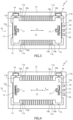
Figure 3 is a top plan view of a part of the MEMS device ofFigure 1 , in a first operating configuration; -
Figure 4 is a top plan view of the part ofFigure 3 , in a second operating configuration; -
Figures 5-7 are graphs showing quantities regarding the MEMS device ofFigure 1 ; -
Figure 8 is a simplified block diagram of a MEMS device according to a different embodiment of the present invention; -
Figure 9 is a graph showing quantities regarding the present invention; -
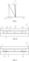
Figure 10 is a cross-sectional view through a MEMS device according to another embodiment of the present invention; -
Figure 11 is a cross-sectional view through a MEMS device according to a further embodiment of the present invention; -
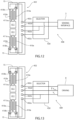
Figure 12 is a top plan view of a part of a MEMS device according to a further embodiment of the present invention, in a first operating configuration; -
Figure 13 is a top plan view of the part ofFigure 12 , in a second operating configuration; -
Figure 14 is a top plan view of a part of a MEMS device according to a further embodiment of the present invention; and -
Figure 15 is a cross-sectional view through the MEMS device ofFigure 14 . - The ensuing description refers to the layout illustrated in the drawings; consequently, terms such as "above", "underneath", "top", "bottom", "up", "down", "right", "left", and the like regard the attached figures and are not to be interpreted in a limiting way.
- With reference to
Figure 1 , a MEMS device is designated as a whole by thenumber 1 and comprises amicrostructure 2, asensing interface 3, an analog-to-digital converter 4, acontrol unit 5, acomparator stage 7, and adriving stage 8. Thesensing interface 3, the analog-to-digital converter 4, thecontrol unit 5, thecomparator stage 7, and thedriving stage 8 may be components of a dedicated integrated circuit or ASIC (Application-Specific Integrated Circuit) 9 coupled to themicrostructure 2. - As specified hereinafter, in an embodiment to which reference will be made for simplicity, the
MEMS device 1 is a linear uniaxial accelerometer of an in-plane type, with a mass that is movable along a sensing axis with respect to a supporting body (which are not illustrated inFigure 1 ) . TheMEMS device 1 may, however, be any device provided with a mass movable with respect to a supporting body. In particular, theMEMS device 1 may be an inertial sensor, for example, a uniaxial accelerometer of the out-of-plane (or teeter-totter) type, a rotational accelerometer, a multiaxial accelerometer, a uniaxial or multiaxial gyroscope. Furthermore, the movable mass is in general a sensing mass or seismic mass, but it may also be a driving mass of a gyroscope. - The
sensing interface 3 receives sensing signals from afirst sensing terminal 2a and from asecond sensing terminal 2b, respectively, of themicrostructure 2 and supplies amplified read signals, which may be used by the analog-to-digital converter 4 for generating digital sensing signals. - The
control unit 5 processes the digital sensing signals and supplies an output signal SOUT indicating a quantity detected through themicrostructure 2, here a linear acceleration according to the sensing axis. - The
comparator stage 7 compares the output signal SOUT with a reference value REF, which indicates an end-of-travel position of the movable mass, and, when a stiction condition is recognized on the basis of the comparison, generates a recovery signal SR. When the recovery signal SR indicates that a stiction condition has been recognized, thedriving stage 8 applies an actuation voltage VA to arecovery terminal 2c of themicrostructure 2. The actuation voltage VA is controlled so as to produce forces that cause detachment of the movable mass, as clarified hereinafter. In one embodiment, the recovery signal SR may be generated, for example, when the comparison indicates that the movable mass has remained in the end-of-travel position for a time longer than a threshold, as illustrated inFigure 2 . Optionally, thedriving stage 8 may generate an auxiliary actuation voltage VAUX, which is applied to thesensing terminals microstructure 2 and produces auxiliary forces to facilitate detachment of the movable mass. -
Figures 3 and 4 , where the supporting body is designated by 10 and the movable mass by 11, show themicrostructure 2 in a resting position and in a stiction condition, respectively. In the stiction condition, themovable mass 11 is withheld in an end-of-travel position (on the right, by way of example inFigure 4 , but a similar situation may occur on the opposite side) by stiction forces FA. - In detail, the
movable mass 11 is connected to the supportingbody 10 by flexures orflexures 12 configured so that themovable mass 11 will be able to oscillate with respect to the supporting body in a main direction X, which here coincides with the sensing axis of theMEMS device 1. In particular, the main direction X is parallel to a major face of themovable mass 11, and the movement of themovable mass 11 is of the in-plane type. - The supporting
body 10 may comprise, for example, asubstrate 14 of semiconductor material and aframe structure 15, defining acavity 16 in which themovable mass 11 is housed. Theframe structure 15 is provided withstopper structures 15a adjacent to the side of themovable mass 11 opposite with respect to the main direction X. Thestopper structures 15a thus limit the movement of themovable mass 11 both in the main direction X (to the right, inFigures 3 and 4 ) and in an opposite direction (to the left, inFigures 3 and 4 ). - In the embodiment of
Figures 3 and 4 , the supportingbody 10 and themovable mass 11 are capacitively coupled by sensing electrodes in a parallel-plate configuration. Alternatively, the sensing electrodes may, for example, be in comb-fingered configuration. In greater detail, the supportingbody 10 comprises first fixedsensing electrodes 10a and second fixedsensing electrodes 10b, coupled, respectively, to thefirst sensing electrode 2a and to thesecond sensing electrode 2b and defined by respective semiconductor plates perpendicular to the main direction X. The first fixedsensing electrodes 10a and the second fixedsensing electrodes 10b are arranged alternating and extend from the supportingframe 15 in thecavity 16 towards respective sides of themovable mass 11 parallel to the main direction X. - The
movable mass 11 is biased in a known way at an operating potential through theflexures 12 andrespective anchorages 17, which are defined by portions of theframe structure 15 electrically insulated from the rest of the supportingbody 10 and connected to an external biasing source through connection lines, here not illustrated for reasons of simplicity. - The
movable mass 11 is further provided withmovable sensing electrodes 11a, which are themselves also defined by semiconductor plates perpendicular to the main direction X. Themovable sensing electrodes 11a extend from the sides of themovable mass 11 parallel to the main direction X towards theframe structure 15 and are each arranged between a respectivefixed sensing electrode 10a and a respective second fixedsensing electrode 10b, thus forming parallel-plate capacitors with capacitance that is variable in a differential way as a function of the position of themovable mass 11. - The
stopper structures 15a are shaped so as to stop themovable mass 11 before themovable sensing electrodes 11a come into contact with the first fixedsensing electrodes 10a or the second fixedsensing electrodes 10b, according to the direction of movement of themovable mass 11. - In conditions of stiction of the
movable mass 11 to the supportingbody 10, in particular, to theframe structure 15, the capacitive coupling between the fixedsensing electrodes fixed electrodes 11a may be exploited for applying an auxiliary force FAUX to themovable mass 11 in the main direction X, by the auxiliary actuation voltage VAUX. - The
microstructure 2 is further provided withrecovery electrodes 18, arranged on the supportingbody 10 and coupled to therecovery terminal 2c by connection lines (not illustrated for reasons of simplicity). In the embodiment ofFigures 3 and 4 , in particular, therecovery electrodes 18 are arranged on theframe structure 15 in positions corresponding torespective recovery portions 11b of themovable mass 11 at opposite ends of themovable mass 11 in the main direction X. In the embodiment ofFigures 3 and 4 , therecovery electrodes 18 face only one side of themovable mass 11, but could be arranged differently according to the design preferences. In some embodiments, there may be present only onerecovery electrode 18. - The
recovery electrodes 18 and therespective recovery portions 11b of themovable mass 11 are capacitively coupled and are shaped so that the recovery voltage VR applied in response to a recovery signal SR causes a transverse actuation force FA in an actuation direction DA transverse to the main direction X and having at least one normal component, perpendicular to the main direction X. In the embodiment ofFigures 3 and 4 , the transverse actuation force FA is substantially perpendicular to the main direction X, coincides with the normal component, and is further parallel to a major face of themovable mass 11. It is, however, understood that the actuation force FA may present also a different orientation. - The
recovery portions 11b of themovable mass 11 may be patterned so that the capacitive coupling with therespective recovery electrodes 18 will meet design preferences. - In practice, the driving
stage 8 and therecovery electrodes 18 define an actuator device that applies the actuation force FA to themovable mass 11 so as to cause detachment from theframe structure 15. - In a condition of stiction of the
movable mass 11 to the supportingbody 10, themovable mass 11 constrained to thestopper structures 15a and theflexures 12 form a mechanical system that has different natural vibration modes, amongst which also natural vibration modes transverse to the main direction X (translational, torsional, or else combined translational and torsional, according to the conformation of the flexures 12). In other words, response of the mechanical system to the loads transverse to the main direction X is resonant around given frequencies, and, given the same energy received, at the resonance frequencies the vibrations have a greater amplitude. - Advantageously, the actuation voltage VA is controlled by the driving
stage 8 so that the actuation force FA will activate at least one natural vibrational mode in a vibration direction transverse to the main direction X. In practice, the actuation voltage VA is an oscillating voltage variable with a frequency band containing at least one resonance frequency of the mechanical system that comprises themovable mass 11 stuck to the supportingstructure 15. Furthermore, for the configuration of therecovery electrodes 18 and of therecovery portions 11b of themovable mass 11 that face them, the transverse actuation force FA caused by the actuation voltage VA is transverse, here substantially perpendicular, to the main direction X. It is noted that the actuation direction DA does not need to be strictly parallel to the vibration direction in order to activate the at least one natural vibrational mode. In fact, it is sufficient that the actuation force FA has a component parallel to the vibration direction to transfer energy and activate the vibration mode. - For this purpose various embodiments are possible.
- In a first case, the natural vibrational modes may be analyzed with simulations or on samples to determine the position of at least one resonance frequency FR. The driving
stage 8 may be configured to generate the actuation voltage VA with an actuation frequency band ΔFA that comprises the resonance frequency FR, as illustrated inFigure 5 . The position and amplitude of the actuation frequency band ΔFA may be selected as a function of the spread of the resonance frequency FR detected during the analysis step. In addition, the drivingstage 8 may be configured to apply the actuation voltage VA at intervals. If, at the end of each interval, thecomparator stage 7 indicates that the stiction situation remains, the drivingstage 8 generates a new voltage interval; otherwise, theMEMS device 1 returns to the normal operating conditions. - In a different embodiment (
Figure 6 ), the drivingstage 8 may be configured to generate the actuation voltage VA as a sequence of pulses or a square wave. - In another embodiment (
Figure 7 ), the drivingstage 8 generates the actuation voltage VA so as to carry out a frequency scan in a programmed recovery range, for example, comprised between 1 and 200 kHz. - According to a further embodiment (illustrated in
Figure 8 ), theMEMS device 1 may be provided with components for determining the frequency response of the mechanical system formed by the supportingbody 10, themovable mass 11, and theflexures 12 in stiction conditions. For instance, the dedicated integrated circuit, here designated by 109, may comprise a frequency-analysis stage 110 having an input coupled to arecovery terminal 2c of themicrostructure 2 and an output that supplies an adjustment signal SADJ to the drivingstage 8. In this case, when thecomparator stage 7 recognizes a stiction situation, the drivingstage 8 applies a test voltage VAT to therecovery terminal 2c of themicrostructure 2, for example a voltage pulse in response to a command issued by thecontrol unit 5. The frequency-analysis stage 110 detects the voltage produced at therecovery terminal 2c as a result of the oscillations of themovable mass 11 in response to the applied test voltage VAT, and determines the spectral content thereof, in particular one or more resonance frequencies. The adjustment signal SADJ is used for adapting the spectrum of the actuation voltage VA on the basis of the result of the analysis conducted by the frequency-analysis stage 110, so that the actuation frequency band ΔFA of the actuation force FA contains the at least one resonance frequency FR. The adjustment signal SADJ may present any useful form; for example, it may be a reference or else contain a list of identified resonance frequencies. - It is understood that the embodiments described above may be combined for generating the actuation voltage VA in one or more modalities according to the design preferences.
- Application of an oscillating actuation force FA transverse to the main direction X contributes to breaking the chemico-physical bonds that are created at the moment of impact of the
movable mass 11 against the supporting body 10 (in particular, thestopper structures 15a of the frame structure 15) and that cause stiction. The effect is amplified by the fact that the transverse actuation force FA is applied so as to activate a natural transverse vibrational mode of the mechanical system that includes the supportingbody 10 and themovable mass 11 in stiction conditions. This enables limitation of the energy to be transferred to themovable mass 11 to obtain separation or, conversely, increase in the effect of separation given the same energy employed. - As already mentioned, however, simultaneously with the actuation voltage VA, the driving
stage 8 may apply an auxiliary actuation voltage VAUX to thesensing terminals microstructure 2 in order to produce auxiliary forces FAUX in the main direction X and facilitate detachment of themovable mass 11 from theframe structure 15. In practice, as a result of the transverse actuation force FA and of the auxiliary forces FAUX, themovable mass 11 is subjected to a resulting force FR that has a normal component FRN (coincident with the normal component of the transverse actuation force FA) and a parallel component FRP that are, respectively, perpendicular and parallel to the main direction X. The parallel component FRP may in particular coincide with the auxiliary force FAUX, if present, or else may comprise a normal component of the transverse actuation force FA, considering that the transverse actuation force FA is not necessarily perpendicular to the main direction. - The transverse actuation force FA and the auxiliary force FAUX are selected so that the parallel component FRP of the resulting force FR (
Figure 9 ) will always be less in modulus than the maximum stiction force FSMAX in the main direction X. In this way, the auxiliary force FAUX cooperates in releasing themovable mass 11, but is not so intense as to cause stiction on the opposite side of the supportingbody 10. In addition to the resulting force FR due to the transverse actuation force FA and to the (possible) auxiliary force FAUX, also forces of inertia due to the movement of theaccelerometer 1 and here not represented may contribute even significantly to detachment of themovable mass 11 from the supportingbody 10. - According to an embodiment illustrated in
Figure 10 , where parts that are the same as those already represented are designated by the same reference numbers, themicrostructure 2 comprises acap 220 that closes thecavity 16 and is provided with electrical connections (not illustrated) for receiving the actuation voltage VA from the driving stage 8 (which is not illustrated here either). A side of thecap 220 facing themovable mass 11 is provided with protrusions that definerecovery electrodes 218 capacitively coupled to themovable mass 11. Also in this case, an actuation voltage VA applied between therecovery electrodes 218 and themovable mass 11 causes a transverse actuation force FA substantially perpendicular to the main direction X (in this case perpendicular also to the major faces of the movable mass 11). - According to the embodiment illustrated in
Figure 11 ,recovery electrodes 318 are arranged on thesubstrate 14 of themicrostructure 2 and are capacitively coupled to themovable mass 11. As in the example ofFigure 10 , an actuation voltage VA applied between therecovery electrodes 318 and themovable mass 11 causes a transverse actuation force FA substantially perpendicular to the main direction X and perpendicular also to the major faces of themovable mass 11. - A further embodiment is illustrated in
Figures 12 and 13 . In this case, the microstructure, here designated by 402, is substantially identical to themicrostructure 2 described previously, but has a first set of first fixedsensing electrodes 410a and secondfixed sensing electrodes 410b, respectively, connected to afirst sensing terminal 402a and to asecond sensing terminal 402b, and a second set of first fixedsensing electrodes 410a and secondfixed sensing electrodes 410b, respectively, connected to athird sensing terminal 402c and to afourth sensing terminal 402d. For instance, the first set comprises the firstfixed sensing electrodes 410a and the secondfixed sensing electrodes 410b on a first side of themovable mass 411, and the second set comprises the firstfixed sensing electrodes 410a and the secondfixed sensing electrodes 410b on a second side of themovable mass 411. - The first
fixed sensing electrodes 410a and the secondfixed sensing electrodes 410b of the first set are used as actuation electrodes for applying to the movable mass 410 transverse actuation forces FA substantially perpendicular to the main direction X. For this purpose, the dedicated integrated circuit, here designated by 409, comprises aselector 430, configured to connect thesensing terminals 402a-402d to thesensing interface 3 and to the drivingstage 8 in different operating conditions. In detail, in normal operating conditions (i.e., in the absence of conditions of stiction of the movable mass 411) theselector 430 connects thefirst sensing terminal 402a and thethird sensing terminal 402c (and thus all the firstfixed sensing electrodes 410a) to a first input of thesensing interface 3, and connects thesecond sensing terminal 402b and thefourth sensing terminal 402d (and thus all the secondfixed sensing electrodes 410b) to a second input of thesensing interface 3. The MEMS device is in sensing configuration, and the capacitive coupling between themovable mass 411 and the supporting body 410 is of a parallel-plate type. - In stiction conditions, the
selector 430 connects thefirst sensing terminal 402a and thesecond sensing terminal 402b (and thus all the firstfixed sensing electrodes 410a and the secondfixed sensing electrodes 410b of the first set) to a terminal of the drivingstage 8 that supplies the actuation voltage VA, and connects thethird sensing terminal 402c (and thus all the firstfixed sensing electrodes 410a of the second set) and thefourth sensing terminal 402c (and thus all the secondfixed sensing electrodes 410b of the second set) to terminals of the drivingstage 9 that supply the auxiliary actuation voltage VAUX. Consequently, all the firstfixed sensing electrodes 410a and the secondfixed sensing electrodes 410b of the first set receive the same actuation voltage VA and are coupled to themovable mass 411 in comb-fingered configuration. As a result of the comb-fingered configuration, the actuation voltage VA causes a transverse actuation force FA on themovable mass 411 in a direction substantially perpendicular to the main direction X. -
Figures 14 and 15 illustrate amicrostructure 502 of a MEMS device according to a further embodiment of the present invention, which comprises a dedicated integrated circuit (not illustrated) substantially as already described. Themicrostructure 502 comprises a supporting body 510 and amovable mass 511. The supporting body 510 includes asubstrate 514 and aframe structure 515, which defines acavity 516 where themovable mass 511 is housed. Acap 520 closes thecavity 516 on a side opposite to thesubstrate 514. - The
movable mass 511 is supported by ananchorage 517 and byflexures 512 in a way rocking about a non-centroidal axis of rotation R that is parallel to major faces of themovable mass 511. The movement of themovable mass 511 is thus of the out-of-plane type. - A
first sensing electrode 510a and asecond sensing electrode 510b are arranged on thesubstrate 514 in positions that are symmetrical with respect to the axis of rotation R and are capacitively coupled to themovable mass 511, which functions as movable sensing electrode. - The
microstructure 502 is further provided withrecovery electrodes 518, arranged on the supporting body 510 and coupled to a recovery terminal 502c by connection lines (not represented for reasons of simplicity). In the embodiment ofFigures 14 and 15 , in particular, therecovery electrodes 518 are arranged on theframe structure 515 in positions corresponding torespective recovery portions 511b of themovable mass 511 at ends of themovable mass 511 opposite to the axis of rotation R. - The
recovery electrodes 518 and therespective recovery portions 511b of themovable mass 511 are capacitively coupled and are shaped so that a recovery voltage VR applied in response to a recovery signal SR will bring about a transverse actuation force FA having at least one normal component perpendicular to a main direction X' of movement. Given that themovable mass 11 is coupled to the supporting body so as to oscillate about the axis of rotation R, the main direction X' of movement is perpendicular to the axis of rotation R. - Finally, it is clear that modifications and variations may be made to the device and method described herein, without thereby departing from the scope of the present invention, as defined in the annexed claims.
- For instance, the number and arrangement of the recovery electrodes are not limited to the configurations described, but may be chosen on the basis of the design preferences, in particular according to the shape, dimensions, and type of movement of the movable mass.
- For the actuation voltage, the MEMS device may use more than one waveform capable of activating natural vibrational modes in a direction transverse to the main direction, either chosen from among the ones described or of some other kind.
- The MEMS device may also be of a multiaxial type, whether in-plane or out-of-plane. In this case, at least one recovery electrode for each main direction is associated to the movable mass.
Claims (15)
- A MEMS (MicroElectroMechanical System) device comprising:a supporting body (10; 410; 510);a movable mass (11; 411; 511), constrained to the supporting body (10; 410; 510) by flexures (12; 512) so as to be able to oscillate in a main direction (X; X');an actuator device (8, 18; 8, 218; 8, 318; 8, 518), configured to apply to the movable mass (11; 411; 511) an electrostatic actuation force (FA), transverse to the main direction (X; X'); anda control circuit (9; 109; 409) configured to detect stiction conditions, in which the movable mass (11; 411; 511) is stuck to the supporting body (10; 410; 510) by a stiction force (FS), and to drive the actuator device (8, 18; 8, 218; 8, 318; 8, 518) in response to recognition of the stiction conditions;wherein the actuation force (FA) is a variable force with an actuation frequency band (ΔFA) containing at least one resonance frequency (FR), in an actuation direction (DA) transverse to the main direction (X; X'), of a mechanical system comprising the movable mass (11; 411; 511) stuck to the supporting body (10; 410; 510), so that the actuation force (FA) will activate at least one natural vibrational mode in a vibration direction transverse to the main direction (X).
- The device according to claim 1, wherein the actuator device (8, 18; 8, 218; 8, 318; 8, 518) comprises:at least one recovery electrode (18; 218; 318; 518), capacitively coupled to the movable mass (11; 411; 511) and configured to apply to the movable mass (11; 411; 511) the actuation force (FA) in the actuation direction (DA) in response to an oscillating actuation voltage (VA); anda driving stage (8) configured to supply the actuation voltage (VA) to the at least one recovery electrode (18; 218; 318; 518).
- The device according to claim 2, wherein the actuation voltage (VA) is a pulsed voltage or a square-wave voltage.
- The device according to claim 2 or claim 3, wherein the driving stage (8) generates the actuation voltage (VA) so as to carry out a frequency scan in a programmed recovery range.
- The device according to any one of claims 2 to 4, wherein the control circuit (9; 109; 409) is configured to determine a frequency response of the mechanical system comprising the movable mass (11; 411; 511) stuck to the supporting body (10; 410; 510) and wherein the driving stage (8) is configured to adapt a spectrum of the actuation voltage (VA) as a function of the frequency response determined, so that the actuation frequency band (ΔFA) of the actuation force (FA) contains the at least one resonance frequency (FR).
- The device according to claim 5, wherein the driving stage (8) is configured to apply a test voltage (VAT) to the at least one recovery electrode (18), and the control circuit (109) comprises a frequency-analysis stage (110) having an input coupled to the at least one recovery electrode (18) and configured to detect a voltage produced as a result of oscillations of the movable mass (11) in response to the test voltage (VAT) and to supply an adjustment signal (SADJ) to the driving stage (8) as a function of the voltage detected, whereby the spectrum of the actuation voltage (VA) is adapted as a function of the frequency response determined, so that the actuation frequency band (ΔFA) of the actuation force (FA) contains the at least one resonance frequency (FR).
- The device according to any one of claims 2 to 6, wherein the supporting body (10; 410; 510) comprises first fixed sensing electrodes (10a; 410a; 510b) and second fixed sensing electrodes (10b; 410b; 510b), and the movable mass comprises movable sensing electrodes (11a) capacitively coupled to respective first fixed sensing electrodes (10a; 410a; 510b) and second fixed sensing electrodes (10b; 410b; 510b) .
- The device according to claim 7, wherein the control circuit (9; 109; 409) comprises a sensing interface (3), and wherein the first fixed sensing electrodes (10a; 410a; 510b) and the second fixed sensing electrodes (10b; 410b; 510b) are connected, respectively, to a first input and to a second input of the sensing interface (3) at least in a first operating configuration.
- The device according to claim 8, wherein the control circuit (409) comprises a selector (430) configured to connect a first set of the first fixed sensing electrodes (410a) and of the second fixed sensing electrodes (410b) to the first input and to the second input of the sensing interface (3) in the first operating configuration and to a terminal of the driving stage (8) that supplies the actuation voltage (VA) in a second operating configuration in stiction conditions.
- The device according to claim 9, wherein the selector (430) is configured to connect a second set of the first fixed sensing electrodes (410a) and of the second fixed sensing electrodes (410b) to the first input and to the second input of the sensing interface (3) in the first operating configuration and to connect the first fixed sensing electrodes (410a) of the second set and the second fixed sensing electrodes (410b) of the second set to terminals of the driving stage (9) that supply an auxiliary actuation voltage (VAUX) in the second operating configuration.
- The device according to claim 8, wherein the driving stage (8) has terminals coupled to the first fixed sensing electrodes (10a; 510b) and to the second fixed sensing electrodes (10b; 510b) and is configured to supply an auxiliary actuation voltage (VAUX) in a second operating configuration.
- The device according to any one of claims 7 to 11, wherein the main direction (X) is parallel to a major face of the movable mass (11; 411; 511), the movement of the movable mass (11; 411; 511) is of the in-plane type, and the first fixed sensing electrodes (10a; 410a; 510b), the second fixed sensing electrodes (10b; 410b; 510b), and the movable sensing electrodes (11a) are capacitively coupled together in a parallel-plate configuration at least in the first operating configuration.
- The device according to any one of claims 2 to 6, wherein:the supporting body (511) comprises a substrate (514);the movable mass (511) is constrained to the supporting body (514) in a way rocking about an axis of rotation (R) that is non-centroidal and parallel to major faces of the movable mass (511), a movement of the movable mass (511) being of the out-of-plane type;the supporting body (511) comprises a first sensing electrode (510a) and a second sensing electrode (510b), arranged on the substrate (514) and capacitively coupled to the movable mass (511); andthe movable mass (511) defines a movable sensing electrode.
- The device according to any one of claims 2 to 13, comprising a plurality of recovery electrodes (18; 218; 318; 518) on the supporting body (10; 410; 510), capacitively coupled to respective recovery portions (11b; 511b) of the movable mass (11; 411; 511).
- A method for controlling a MEMS (MicroElectroMechanical System) device comprising a supporting body (10; 410; 510 and a movable mass (11; 411; 511), constrained to the supporting body (10; 410; 510) by flexures (12; 512) so as to be able to oscillate in a main direction (X; X');
the method comprising:detecting stiction conditions, in which the movable mass (11; 411; 511) is stuck to the supporting body (10; 410; 510) by a stiction force (FS); andin response to recognition of the stiction conditions, applying to the movable mass (11; 411; 511) an electrostatic actuation force (FA), transverse to the main direction (X; X');wherein the actuation force (FA) is a variable force with an actuation frequency band (ΔFA) containing at least one resonance frequency (FR), in an actuation direction (DA) transverse to the main direction (X; X'), of a mechanical system comprising the movable mass (11; 411; 511) stuck to the supporting body (10; 410; 510), so that the actuation force (FA) will activate at least one natural vibrational mode in a vibration direction transverse to the main direction (X).
Applications Claiming Priority (1)
| Application Number | Priority Date | Filing Date | Title |
|---|---|---|---|
| IT102023000016743A IT202300016743A1 (en) | 2023-08-04 | 2023-08-04 | MICROELECTROMECHANICAL DEVICE WITH RECOVERY FROM ADHESION CONDITIONS |
Publications (1)
| Publication Number | Publication Date |
|---|---|
| EP4502536A1 true EP4502536A1 (en) | 2025-02-05 |
Family
ID=88290439
Family Applications (1)
| Application Number | Title | Priority Date | Filing Date |
|---|---|---|---|
| EP24192288.9A Pending EP4502536A1 (en) | 2023-08-04 | 2024-08-01 | Microelectromechanical device with recovery from stiction conditions |
Country Status (4)
| Country | Link |
|---|---|
| US (1) | US20250042718A1 (en) |
| EP (1) | EP4502536A1 (en) |
| CN (1) | CN119430063A (en) |
| IT (1) | IT202300016743A1 (en) |
Citations (3)
| Publication number | Priority date | Publication date | Assignee | Title |
|---|---|---|---|---|
| US20150002982A1 (en) * | 2013-06-28 | 2015-01-01 | Maxim Integrated Products, Inc. | Recovery system and methods for MEMS devices |
| US20180113147A1 (en) * | 2016-10-26 | 2018-04-26 | Nxp Usa, Inc. | Stiction detection and recovery in a micro-electro-mechanical system device |
| EP2805913B1 (en) * | 2013-05-23 | 2022-10-19 | NXP USA, Inc. | Active lateral force stiction self-recovery for microelectromechanical systems devices |
-
2023
- 2023-08-04 IT IT102023000016743A patent/IT202300016743A1/en unknown
-
2024
- 2024-07-25 US US18/784,719 patent/US20250042718A1/en active Pending
- 2024-08-01 EP EP24192288.9A patent/EP4502536A1/en active Pending
- 2024-08-01 CN CN202411049154.XA patent/CN119430063A/en active Pending
Patent Citations (3)
| Publication number | Priority date | Publication date | Assignee | Title |
|---|---|---|---|---|
| EP2805913B1 (en) * | 2013-05-23 | 2022-10-19 | NXP USA, Inc. | Active lateral force stiction self-recovery for microelectromechanical systems devices |
| US20150002982A1 (en) * | 2013-06-28 | 2015-01-01 | Maxim Integrated Products, Inc. | Recovery system and methods for MEMS devices |
| US20180113147A1 (en) * | 2016-10-26 | 2018-04-26 | Nxp Usa, Inc. | Stiction detection and recovery in a micro-electro-mechanical system device |
Also Published As
| Publication number | Publication date |
|---|---|
| IT202300016743A1 (en) | 2025-02-04 |
| US20250042718A1 (en) | 2025-02-06 |
| CN119430063A (en) | 2025-02-14 |
Similar Documents
| Publication | Publication Date | Title |
|---|---|---|
| CN102356300B (en) | Drive frequency tunable mems gyroscope | |
| EP0840092B1 (en) | A complementary electrostatic driving apparatus for a micro-actuator | |
| US8272266B2 (en) | Gyroscopes using surface electrodes | |
| CN100520299C (en) | Micro electro mechanical system device, speed reduction stop block, method for reducing impact and gyroscope | |
| JP2006053152A (en) | Microgyrometer employing frequency detection | |
| EP2485060B1 (en) | A MEMS vibrating-beam accelerometer with piezoelectric drive | |
| US6125700A (en) | Vibrating type angular velocity sensor | |
| WO2009057990A2 (en) | Capacitive area-changed mems gyroscope with adjustable resonance frequencies | |
| US20170052027A1 (en) | Vibration angular velocity sensor | |
| WO2008021144A2 (en) | Mems comb drive actuators and method of manufacture | |
| JP4899781B2 (en) | Capacitive mechanical quantity detector | |
| JP6067102B2 (en) | Angular velocity sensor | |
| JPH02248865A (en) | Acceleration detector | |
| US20250042718A1 (en) | Microelectromechanical device with recovery from stiction conditions | |
| US6792802B2 (en) | Noise source for starting MEMS gyroscope | |
| KR20130067419A (en) | Inertial sensor and measuring method for acceleration using the same | |
| CN100473948C (en) | Symmetric-structure double-grade decoupling single-crystal-silicon micro mechanical gyroscope | |
| WO1999019689A1 (en) | Angular velocity sensor | |
| CN112088483B (en) | Electrostatic actuator and physical quantity sensor | |
| US10914586B2 (en) | Vibration apparatus | |
| WO2004068075A1 (en) | Methods and systems for reducing stick-down within mems structures | |
| US20160131481A1 (en) | Mems inertial sensing using acoustic waves | |
| JP2013174576A (en) | Inertial sensor | |
| JPH05322925A (en) | Semiconductor acceleration sensor with driving part for self-diagnosis | |
| JP2005283584A (en) | Sensor having drive / detection means, drive unit and evaluation unit |
Legal Events
| Date | Code | Title | Description |
|---|---|---|---|
| PUAI | Public reference made under article 153(3) epc to a published international application that has entered the european phase |
Free format text: ORIGINAL CODE: 0009012 |
|
| STAA | Information on the status of an ep patent application or granted ep patent |
Free format text: STATUS: THE APPLICATION HAS BEEN PUBLISHED |
|
| AK | Designated contracting states |
Kind code of ref document: A1 Designated state(s): AL AT BE BG CH CY CZ DE DK EE ES FI FR GB GR HR HU IE IS IT LI LT LU LV MC ME MK MT NL NO PL PT RO RS SE SI SK SM TR |
|
| STAA | Information on the status of an ep patent application or granted ep patent |
Free format text: STATUS: REQUEST FOR EXAMINATION WAS MADE |
|
| 17P | Request for examination filed |
Effective date: 20250804 |