EP4502505A1 - Air conditioner - Google Patents
Air conditioner Download PDFInfo
- Publication number
- EP4502505A1 EP4502505A1 EP23780897.7A EP23780897A EP4502505A1 EP 4502505 A1 EP4502505 A1 EP 4502505A1 EP 23780897 A EP23780897 A EP 23780897A EP 4502505 A1 EP4502505 A1 EP 4502505A1
- Authority
- EP
- European Patent Office
- Prior art keywords
- heat transfer
- transfer tube
- fin
- fins
- air conditioner
- Prior art date
- Legal status (The legal status is an assumption and is not a legal conclusion. Google has not performed a legal analysis and makes no representation as to the accuracy of the status listed.)
- Pending
Links
Images




Classifications
-
- F—MECHANICAL ENGINEERING; LIGHTING; HEATING; WEAPONS; BLASTING
- F28—HEAT EXCHANGE IN GENERAL
- F28F—DETAILS OF HEAT-EXCHANGE AND HEAT-TRANSFER APPARATUS, OF GENERAL APPLICATION
- F28F1/00—Tubular elements; Assemblies of tubular elements
- F28F1/10—Tubular elements and assemblies thereof with means for increasing heat-transfer area, e.g. with fins, with projections, with recesses
-
- F—MECHANICAL ENGINEERING; LIGHTING; HEATING; WEAPONS; BLASTING
- F25—REFRIGERATION OR COOLING; COMBINED HEATING AND REFRIGERATION SYSTEMS; HEAT PUMP SYSTEMS; MANUFACTURE OR STORAGE OF ICE; LIQUEFACTION SOLIDIFICATION OF GASES
- F25B—REFRIGERATION MACHINES, PLANTS OR SYSTEMS; COMBINED HEATING AND REFRIGERATION SYSTEMS; HEAT PUMP SYSTEMS
- F25B39/00—Evaporators; Condensers
- F25B39/02—Evaporators
-
- F—MECHANICAL ENGINEERING; LIGHTING; HEATING; WEAPONS; BLASTING
- F24—HEATING; RANGES; VENTILATING
- F24F—AIR-CONDITIONING; AIR-HUMIDIFICATION; VENTILATION; USE OF AIR CURRENTS FOR SCREENING
- F24F1/00—Room units for air-conditioning, e.g. separate or self-contained units or units receiving primary air from a central station
- F24F1/0003—Room units for air-conditioning, e.g. separate or self-contained units or units receiving primary air from a central station characterised by a split arrangement, wherein parts of the air-conditioning system, e.g. evaporator and condenser, are in separately located units
-
- F—MECHANICAL ENGINEERING; LIGHTING; HEATING; WEAPONS; BLASTING
- F24—HEATING; RANGES; VENTILATING
- F24F—AIR-CONDITIONING; AIR-HUMIDIFICATION; VENTILATION; USE OF AIR CURRENTS FOR SCREENING
- F24F13/00—Details common to, or for air-conditioning, air-humidification, ventilation or use of air currents for screening
- F24F13/22—Means for preventing condensation or evacuating condensate
-
- F—MECHANICAL ENGINEERING; LIGHTING; HEATING; WEAPONS; BLASTING
- F24—HEATING; RANGES; VENTILATING
- F24F—AIR-CONDITIONING; AIR-HUMIDIFICATION; VENTILATION; USE OF AIR CURRENTS FOR SCREENING
- F24F13/00—Details common to, or for air-conditioning, air-humidification, ventilation or use of air currents for screening
- F24F13/30—Arrangement or mounting of heat-exchangers
-
- F—MECHANICAL ENGINEERING; LIGHTING; HEATING; WEAPONS; BLASTING
- F25—REFRIGERATION OR COOLING; COMBINED HEATING AND REFRIGERATION SYSTEMS; HEAT PUMP SYSTEMS; MANUFACTURE OR STORAGE OF ICE; LIQUEFACTION SOLIDIFICATION OF GASES
- F25B—REFRIGERATION MACHINES, PLANTS OR SYSTEMS; COMBINED HEATING AND REFRIGERATION SYSTEMS; HEAT PUMP SYSTEMS
- F25B39/00—Evaporators; Condensers
- F25B39/04—Condensers
-
- F—MECHANICAL ENGINEERING; LIGHTING; HEATING; WEAPONS; BLASTING
- F28—HEAT EXCHANGE IN GENERAL
- F28D—HEAT-EXCHANGE APPARATUS, NOT PROVIDED FOR IN ANOTHER SUBCLASS, IN WHICH THE HEAT-EXCHANGE MEDIA DO NOT COME INTO DIRECT CONTACT
- F28D1/00—Heat-exchange apparatus having stationary conduit assemblies for one heat-exchange medium only, the media being in contact with different sides of the conduit wall, in which the other heat-exchange medium is a large body of fluid, e.g. domestic or motor car radiators
- F28D1/02—Heat-exchange apparatus having stationary conduit assemblies for one heat-exchange medium only, the media being in contact with different sides of the conduit wall, in which the other heat-exchange medium is a large body of fluid, e.g. domestic or motor car radiators with heat-exchange conduits immersed in the body of fluid
- F28D1/04—Heat-exchange apparatus having stationary conduit assemblies for one heat-exchange medium only, the media being in contact with different sides of the conduit wall, in which the other heat-exchange medium is a large body of fluid, e.g. domestic or motor car radiators with heat-exchange conduits immersed in the body of fluid with tubular conduits
- F28D1/053—Heat-exchange apparatus having stationary conduit assemblies for one heat-exchange medium only, the media being in contact with different sides of the conduit wall, in which the other heat-exchange medium is a large body of fluid, e.g. domestic or motor car radiators with heat-exchange conduits immersed in the body of fluid with tubular conduits the conduits being straight
-
- F—MECHANICAL ENGINEERING; LIGHTING; HEATING; WEAPONS; BLASTING
- F28—HEAT EXCHANGE IN GENERAL
- F28F—DETAILS OF HEAT-EXCHANGE AND HEAT-TRANSFER APPARATUS, OF GENERAL APPLICATION
- F28F1/00—Tubular elements; Assemblies of tubular elements
- F28F1/10—Tubular elements and assemblies thereof with means for increasing heat-transfer area, e.g. with fins, with projections, with recesses
- F28F1/12—Tubular elements and assemblies thereof with means for increasing heat-transfer area, e.g. with fins, with projections, with recesses the means being only outside the tubular element
- F28F1/24—Tubular elements and assemblies thereof with means for increasing heat-transfer area, e.g. with fins, with projections, with recesses the means being only outside the tubular element and extending transversely
- F28F1/32—Tubular elements and assemblies thereof with means for increasing heat-transfer area, e.g. with fins, with projections, with recesses the means being only outside the tubular element and extending transversely the means having portions engaging further tubular elements
- F28F1/325—Fins with openings
-
- F—MECHANICAL ENGINEERING; LIGHTING; HEATING; WEAPONS; BLASTING
- F28—HEAT EXCHANGE IN GENERAL
- F28F—DETAILS OF HEAT-EXCHANGE AND HEAT-TRANSFER APPARATUS, OF GENERAL APPLICATION
- F28F2215/00—Fins
- F28F2215/04—Assemblies of fins having different features, e.g. with different fin densities
-
- F—MECHANICAL ENGINEERING; LIGHTING; HEATING; WEAPONS; BLASTING
- F28—HEAT EXCHANGE IN GENERAL
- F28F—DETAILS OF HEAT-EXCHANGE AND HEAT-TRANSFER APPARATUS, OF GENERAL APPLICATION
- F28F2225/00—Reinforcing means
- F28F2225/06—Reinforcing means for fins
Definitions
- the present disclosure relates to an air conditioner.
- Patent Literature 1 JP 2001-304783 A
- an air conditioner configured by connecting an indoor unit including an indoor heat exchanger and an outdoor unit including an outdoor heat exchanger is known.
- a heat transfer tube penetrates a plurality of fins.
- An air conditioner includes an outdoor unit and an indoor unit.
- the outdoor unit includes a first heat exchanger.
- the first heat exchanger includes a first heat transfer tube and a plurality of first fins.
- the first heat transfer tube is made of aluminum or an aluminum alloy.
- the plurality of first fins is made of aluminum or an aluminum alloy.
- the indoor unit includes a second heat exchanger.
- the second heat exchanger includes a second heat transfer tube and a plurality of second fins.
- the second heat transfer tube is made of aluminum or an aluminum alloy.
- the plurality of second fins is made of aluminum or an aluminum alloy.
- a first sacrificial layer is provided on a surface of the first heat transfer tube.
- the first sacrificial layer is lower in potential than a base material of the first heat transfer tube and lower in potential than the first fins.
- a fin pitch of the first fins is larger than a fin pitch of the second fins.
- the first sacrificial layer which is lower in potential than the base material is provided in the first heat transfer tube made of aluminum or an aluminum alloy, corrosion of the base material can be suppressed.
- the first sacrificial layer, which is lower in potential than the first fin made of aluminum or an aluminum alloy may be corroded due to the first fins.
- the fin pitch of the first fins of the first heat exchanger is made larger than the fin pitch of the second fins of the second heat exchanger.
- a surface area of the first fin in contact with the first sacrificial layer of the first heat transfer tube can be reduced.
- corrosion of the first sacrificial layer can be suppressed.
- An air conditioner according to a second aspect is the air conditioner according to the first aspect, in which the first heat transfer tube and the second heat transfer tube have a cylindrical shape.
- the air conditioner of the present disclosure is suitably used for the air conditioner including the first heat exchanger having the cylindrical first heat transfer tube and the second heat exchanger having the cylindrical second heat transfer tube.
- An air conditioner according to a third aspect is the air conditioner according to the first or second aspect, in which a first surface layer containing a resin is provided on a surface of the first fin.
- a corrosion rate of the first sacrificial layer can be reduced by an electric resistance between the first surface layer containing a resin and the first heat transfer tube.
- An air conditioner according to a fourth aspect is the air conditioner according to the third aspect, in which a second surface layer containing a resin is provided on a surface of the second fin. A thickness of the first surface layer is larger than a thickness of the second surface layer.
- the electric resistance between the first surface layer of the outdoor unit and the first heat transfer tube, which are susceptible to salt damage, can be made larger than an electric resistance between the second surface layer of the indoor unit and the second heat transfer tube. Therefore, the corrosion rate of the first sacrificial layer can be further reduced.
- An air conditioner according to a fifth aspect is the air conditioner according to any of the first to fourth aspects, in which a second sacrificial layer is provided on a surface of the second heat transfer tube.
- the second sacrificial layer is lower in potential than a base material of the second heat transfer tube and lower in potential than the second fins.
- the second sacrificial layer which is lower in potential than the base material is provided in the second heat transfer tube made of aluminum or an aluminum alloy, corrosion of the base material can be suppressed.
- the second sacrificial layer is lower in potential than the second fins, it is possible to suppress deterioration in workability of the second fins.
- An air conditioner according to a sixth aspect is the air conditioner according to any of the first to fifth aspects, in which a difference between the fin pitch of the first fins and the fin pitch of the second fins is 0.1 mm or more and 0.3 mm or less.
- the corrosion of the first sacrificial layer can be further suppressed by setting the pitch difference to 0.1 mm or more and 0.3 mm or less.
- An air conditioner according to a seventh aspect is the air conditioner according to any of the first to sixth aspects, in which the fin pitch of the first fins is more than 1.0 times and less than 1.3 times the fin pitch of the second fins.
- the corrosion of the first sacrificial layer can be further suppressed.
- An air conditioner according to an eighth aspect is the air conditioner according to any of the first to seventh aspects, in which a second sacrificial layer is provided on a surface of the second heat transfer tube.
- the second sacrificial layer is lower in potential than the base material of the second heat transfer tube.
- a thickness of the first sacrificial layer and a thickness of the second sacrificial layer are the same.
- the first sacrificial layer of the first heat transfer tube and the second sacrificial layer of the second heat transfer tube can be made common, a production efficiency of the first heat exchanger and the second heat exchanger can be improved.
- An air conditioner according to a ninth aspect is the air conditioner according to any of the first to eighth aspects, in which an outer diameter of the first transfer tube and an outer diameter of the second heat transfer tube are the same.
- the outer diameter of the first heat transfer tube and the outer diameter of the second heat transfer tube can be made common, the production efficiency of the first heat exchanger and the second heat exchanger can be improved.
- An air conditioner according to a tenth aspect is the air conditioner according to any of the first to ninth aspects, in which a material of the first transfer tube and a material of the second heat transfer tube are the same.
- the material of the first heat transfer tube and the material of the second heat transfer tube can be made common, the production efficiency of the first heat exchanger and the second heat exchanger can be improved.
- An air conditioner according to an eleventh aspect is the air conditioner according to any of the first to tenth aspects, in which the outdoor unit further includes a first drain pan that receives water.
- the indoor unit further includes a second drain pan that receives water.
- a plurality of the first heat transfer tubes and a plurality of the second heat transfer tubes are provided. A lowermost end of the plurality of first heat transfer tubes is located above a water level of the first drain pan. A lowermost end of the plurality of second heat transfer tubes is located above a water level of the second drain pan.
- the air conditioner according to the eleventh aspect it is possible to prevent the water in the first drain pan from adhering to the first heat transfer tube, and it is possible to prevent the water in the second drain pan from adhering to the second heat transfer tube. Therefore, corrosion of the first heat transfer tube due to water in the first drain pan can be suppressed, and corrosion of the second heat transfer tube due to water in the second drain pan can be suppressed.
- An air conditioner according to a twelfth aspect is the air conditioner according to any of the first to eleventh aspects, in which the plurality of first fins is stacked in a first direction in which the first heat transfer tubes extend, and includes a first collar through which the first heat transfer tube passes.
- the first collar portion includes the first upright portion, the flat portion, the second upright portion, and the flange.
- the first upright portion extends in the first direction from the fin body.
- the flat portion extends from the first upright portion toward the first heat transfer tube.
- the second upright portion extends from the flat portion along the first heat transfer tube.
- the flange extends outward from the second upright portion.
- One flat portion is in contact with the flange of another adjacent first fin.
- the plurality of second fins is stacked in a second direction in which the second heat transfer tubes extend, and includes a second collar through which the second heat transfer tube passes.
- the second collar includes a first upright portion, a flat portion, a second upright portion, and a flange.
- the first upright portion extends in the second direction from the fin body.
- the flat portion extends from the first upright portion toward the second heat transfer tube.
- the second upright portion extends from the flat portion along the second heat transfer tube.
- the flange extends outward from the second upright portion.
- One flat portion is in contact with the flange of another adjacent second fin.
- the air conditioner of the present disclosure is suitably used for the air conditioner including the first heat exchanger having the first fin and the second heat exchanger having the second fin having such a structure.
- the air conditioner of the present disclosure is suitably used for the air conditioner including the first heat exchanger having the first fin and the second heat exchanger having the second fin having such a structure.
- An air conditioner according to a fourteenth aspect is the air conditioner according to any of the first to fourth aspects, in which a second sacrificial layer is provided on a surface of the second heat transfer tube.
- the second sacrificial layer is lower in potential than the base material of the second heat transfer tube and higher in potential than the second fins.
- the second sacrificial layer which is lower in potential than the base material is provided in the second heat transfer tube made of aluminum or an aluminum alloy, corrosion of the base material can be suppressed. Since the second sacrificial layer is higher in potential than the second fin, even when the fin pitch is smaller, corrosion of the second sacrificial layer by the second fin can be suppressed.
- the rate of zinc content of the first fin of the outdoor unit susceptible to salt damage is higher than the rate of zinc content of the second fin of the indoor unit, the potential of the first fin can be lowered. Therefore, a potential difference between the first fin and the first sacrificial layer can be reduced. As a result, corrosion of the first sacrificial layer can be further suppressed.
- an air conditioner 1 includes an outdoor unit 2, an indoor unit 3, and a connection pipe 4.
- the outdoor unit 2 is installed outdoors.
- the indoor unit 3 is installed indoors.
- the indoor unit 3 is attached to an indoor wall surface or the like.
- the connection pipe 4 connects the outdoor unit 2 and the indoor unit 3.
- Such an air conditioner 1 can perform a cooling operation, a heating operation, and the like indoors.
- the outdoor unit 2 includes a first heat exchanger 200, a first fan 21, a first drain pan 22, and the like.
- the first fan 21 sucks outdoor air into the outdoor unit 2, supplies the outdoor air to the first heat exchanger 200, and then discharges the outdoor air to the outside of the outdoor unit 2.
- the first heat exchanger 200 exchanges heat between the outdoor air and a refrigerant.
- the first heat exchanger 200 is a heat exchanger that functions as a radiator for the refrigerant during the cooling operation, and functions as an evaporator for the refrigerant during the heating operation.
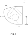
- the first drain pan 22 receives water.
- the indoor unit 3 includes a second heat exchanger 300, a second fan 31, a second drain pan 32, and the like.
- the second fan 31 sucks indoor air into the indoor unit 3, supplies the indoor air to the second heat exchanger 300, and then discharges the indoor air to the outside of the indoor unit 3.
- the second heat exchanger 300 exchanges heat between the refrigerant and the indoor air.
- the second heat exchanger 300 is a heat exchanger that functions as an evaporator for the refrigerant during the cooling operation, and functions as a radiator for the refrigerant during the heating operation.
- the second drain pan 32 receives water.
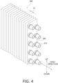
- the first heat exchanger 200 includes a plurality of first heat transfer tubes 210 and a plurality of first fins 220.
- the first heat transfer tubes 210 and the first fins 220 are made of aluminum or an aluminum alloy.
- the first heat exchanger 200 according to the present embodiment is a cross-fin-tube heat exchanger.
- the first heat transfer tubes 210 each allow the refrigerant to flow therethrough.
- the first heat transfer tube 210 has a cylindrical shape.
- the first heat transfer tube 210 is a round tube.
- the first heat transfer tube 210 is provided with a through hole through which the refrigerant that exchanges heat with the outdoor air in the first heat exchanger 200 passes.
- the through hole of the first heat transfer tube 210 penetrates along a first direction.
- the first direction is a longitudinal direction.
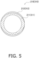
- the first heat transfer tube 210 includes a first base material 211 and a first sacrificial layer 212.
- the first sacrificial layer 212 is provided on a surface of the first heat transfer tube 210.
- the first sacrificial layer 212 may be provided on the entire surface of the first heat transfer tube 210, or may be provided on a part of the surface of the first heat transfer tube 210 as illustrated in FIG. 5 .
- the first sacrificial layer 212 may be formed on an entire exposed outer surface, or may be formed on a part of the exposed outer surface as illustrated in FIG. 5 .
- the first sacrificial layer 212 is formed in a part in a thickness direction from the outer surface of the first heat transfer tube 210 toward an inner surface through which the refrigerant flows, and is not formed in an entire thickness. In other words, in the first heat transfer tube 210, the first sacrificial layer 212 is not formed on at least a part of the inner surface through which the refrigerant flows. In the present embodiment, the first sacrificial layer 212 is not formed on the entire inner surface of the first heat transfer tube 210.
- the first sacrificial layer 212 is lower in potential than the first base material 211 of the first heat transfer tube 210 and lower in potential than the first fin 220.
- the potential difference between the potential of the first sacrificial layer 212 and the potential of the first base material 211 is, for example, 226 mV.
- the potential difference between the potential of the first sacrificial layer 212 and the potential of the first fin 220 is, for example, 180 mV.
- the first sacrificial layer 212 contains a metal such as zinc (Zn) in order to lower the potential.
- the first sacrificial layer 212 according to the present embodiment is a zinc diffusion layer sprayed with zinc.
- the first sacrificial layer 212 on the outer surface side prevents a progress of corrosion of the first base material 211 on the inner surface side in the first heat transfer tube 210.
- the plurality of first heat transfer tubes 210 is aligned in an up-down direction.
- a lowermost end of each of the plurality of first heat transfer tubes 210 is located above a water level of the first drain pan 22 (see FIG. 2 ).
- the lowermost end of each of the plurality of first heat transfer tubes 210 is located above a highest water level when the first drain pan 22 receives a maximum amount of water.
- the first fin 220 increases a heat transfer area between the first heat transfer tube 210 and the outdoor air to promote heat exchange between the refrigerant and the outdoor air.
- the first fin 220 is in contact with the first heat transfer tube 210.
- the first fin 220 is lower in potential than the first base material 211 of the first heat transfer tube 210 and higher in potential than the first sacrificial layer 212.
- the first base material 211, the first fin 220, and the first sacrificial layer 212 have higher potentials in that order.
- the potential difference between the potential of the first fin 220 and the potential of the first base material 211 is, for example, 46 mV.
- the first fin 220 according to the present embodiment contains zinc.
- the rate of zinc content of the first fin 220 is preferably 0.5 mass% or more.
- the "rate of zinc content" described in the present specification is a value measured by, for example, an emission spectroscopic analysis method.
- the first fin 220 includes a first body 220a and a first surface layer 220b.
- the first surface layer 220b is provided on a surface of the first body 220a.
- the first surface layers 220b are provided on both surfaces extending in an extending direction of the first body 220a.
- a thickness W220b of the first surface layer 220b is smaller than a thickness W220a of the first body 220a.
- Each thickness of the first fin 220 is a maximum value of a distance in the first direction from the outer surface toward the inside.
- the first surface layer 220b contains a resin.
- the resin has electric resistance.
- An electrical conductivity of the first surface layer 220b is smaller than an electrical conductivity of the first body 220a.
- the first surface layer 220b is a layer formed by performing a surface treatment on the surface of the first body 220a.
- the first surface layer 220b imparts hydrophilicity, corrosion resistance, and the like to the first fin 220.
- the first surface layer 220b may be a single layer or a plurality of layers.
- An electric resistance value of the first surface layer 220b is preferably 1 ⁇ 10 4 ⁇ or more and 1 ⁇ 10 10 ⁇ or less, and more preferably 1 ⁇ 10 5 ⁇ or more and 1 ⁇ 10 8 ⁇ or less.
- the plurality of first fins 220 is stacked in the first direction (see FIG. 4 ) in which the first heat transfer tubes 210 extend.
- the plurality of first fins 220 extends in the up-down direction so as to cross (be orthogonal to in FIG. 4 ) the first heat transfer tubes 210.
- the plurality of first fins 220 is disposed in parallel and at equal intervals. In other words, the plurality of first fins 220 is aligned in the first direction at a predetermined fin pitch P1.
- the plurality of first fins 220 each includes a fin body 221 and a first collar 222.
- the fin body 221 is a flat plate-shaped member.
- the first collar 222 allows the first heat transfer tube 210 to pass therethrough.
- the first collar 222 has a through hole through which the first heat transfer tube 210 passes.
- the first collar 222 includes a first upright portion 223, a flat portion 224, a second upright portion 225, and a flange 226.
- the first upright portion 223, the flat portion 224, the second upright portion 225, and the flange 226 are constituted by one member.
- the first upright portion 223, the flat portion 224, the second upright portion 225, and the flange 226 are constituted by nesting.
- the first upright portion 223 extends in the first direction from the fin body 221.
- the first upright portion 223 is orthogonal to the fin body 221.
- a coupling portion between the first upright portion 223 and the fin body 221 has a curved (R) shape.
- the second direction and the first direction are illustrated as the same direction, but the second direction may be different from the first direction.
- the first upright portion 323 extends in the second direction from the fin body 321.
- the first upright portion 323 is orthogonal to the fin body 321.
- a coupling portion between the first upright portion 323 and the fin body 321 has a curved (R) shape.
- the flat portion 324 extends from the first upright portion 323 toward the second heat transfer tube 310.
- the flat portion 324 is orthogonal to the first upright portion 323.
- a coupling portion between flat portion 324 and first upright portion 323 has a curved shape.
- the second upright portion 325 extends from the flat portion 324 along the second heat transfer tube 310.
- the second upright portion 325 is in contact with the second heat transfer tube 310.
- the second upright portion 325 is orthogonal to the flat portion 324.
- a coupling portion between second upright portion 325 and flat portion 324 has a curved shape.
- the flange 326 extends outward from the second upright portion 325.
- the flange 326 is orthogonal to the second upright portion 325.
- the coupling portion between the flange 326 and the second upright portion 325 has a curved shape.
- the coupling portion has a curvature radius of 0.2 mm or more.
- the fin pitch P1 of the first fins 220 illustrated in FIG. 4 is larger than the fin pitch P2 of the second fins 320 illustrated in FIG. 8 .
- the fin pitch P1 is a distance between the adjacent first fins 220.
- the fin pitch P1 is a distance between opposing faces of the adjacent first fins 220.
- the fin pitch P2 is a distance between the adjacent second fins 320.
- the fin pitch P2 is a distance between opposing faces of the adjacent second fins 320.
- a difference between the fin pitch P1 of the first fins 220 and the fin pitch P2 of the second fins 320 is 0.1 mm or more and 0.3 mm or less.
- a pitch difference (fin pitch P1 - fin pitch P2) is 0.1 mm or more and 0.3 mm or less.
- the fin pitch P1 of the first fins 220 is 1.4 mm or more and 1.5 mm or less.
- the fin pitch P2 of the second fins 320 is 1.2 mm or more and 1.4 mm or less.
- the outer diameter of the first heat transfer tube 210 and the outer diameter of the second heat transfer tube 310 are the same.
- the inner diameter of the first heat transfer tube 210 and the inner diameter of the second heat transfer tube 310 are the same.
- the material of the first heat transfer tube 210 and the material of the second heat transfer tube 310 are the same. Specifically, the material of the first base material 211 and the material of the second base material 311 are the same. The material of the first sacrificial layer 212 and the material of the second sacrificial layer 312 are the same.
- the material of the first fin 220 and the material of the second fin 320 may be the same, but preferably, the rate of zinc content of the first fin 220 is larger than the rate of zinc content of the second fin 320, and for example, the rate of zinc content of the first fin 220 is larger than the rate of zinc content of the second fin 320 by 0.2 mass% or more.
- the electrical conductivity of the first surface layer 220b and the electrical conductivity of the second surface layer 320b may be completely the same, and a case where the ratio of the electrical conductivity of the first surface layer 220b to the electrical conductivity of the second surface layer 320b (the electrical conductivity of the first surface layer 220b/the electrical conductivity of the second surface layer 320b) is 1.1 times or less is included.
- the thickness of the first fin 220 and the thickness of the second fin 320 may be the same, but are different in the present embodiment.
- the thickness of the first fin 220 is smaller than the thickness of the second fin.
- the thickness W220a of the first body 220a of the first fin 220 illustrated in FIG. 10 is smaller than the thickness W320a of the second body 320a of the second fin 320 illustrated in FIG. 11 .
- the thickness W220b of the first surface layer 220b of the first fin 220 illustrated in FIG. 10 is larger than the thickness W320b of the second surface layer 320b of the second fin 320 illustrated in FIG. 11 .
- the thickness W220b of the first surface layer 220b is preferably 1.1 times or more, more preferably 1.2 times or more, and still more preferably 1.5 times or more the thickness W320b of the second surface layer 320b.
- the electric resistance value of the first surface layer 220b is preferably 1.2 times or more the electric resistance value of the second surface layer 320b.
- the air conditioner 1 includes the outdoor unit 2 and the indoor unit 3.
- the outdoor unit 2 includes the first heat exchanger 200.
- the first heat exchanger 200 includes the first heat transfer tube 210 and the plurality of first fins 220.
- the first heat transfer tubes 210 are made of aluminum or an aluminum alloy.
- the plurality of first fins 220 is made of aluminum or an aluminum alloy.
- the indoor unit 3 includes the second heat exchanger 300.
- the second heat exchanger 300 includes the second heat transfer tube 310 and the plurality of second fins 320.
- the second heat transfer tubes 310 are made of aluminum or an aluminum alloy.
- the plurality of second fins 320 is made of aluminum or an aluminum alloy.
- the first sacrificial layer 212 is provided on the surface of the first heat transfer tube 210.
- the first sacrificial layer 212 is lower in potential than the first base material 211 of the first heat transfer tube 210 and lower in potential than the first fin 220.
- the fin pitch P1 of the first fins 220 is larger than the fin pitch P2 of the second fins 320.
- the first sacrificial layer 212 which is lower in potential than the first base material 211 is provided in the first heat transfer tube 210 made of aluminum or an aluminum alloy, corrosion of the first base material 211 can be suppressed.
- the first sacrificial layer 212 is lower in potential than the first fin 220 made of aluminum or an aluminum alloy. Therefore, when a water droplet adheres across the first fin 220 and the first sacrificial layer 212, a potential difference is generated, and the first sacrificial layer 212 is consumed by the first fin 220. If rapidly consumed, the first sacrificial layer 212 fails to protect the first base material 211.
- the fin pitch P1 of the first fins 220 of the first heat exchanger 200 is made larger than the fin pitch P2 of the second fins 320 of the second heat exchanger 300. Therefore, by reducing the number of the first fins 220, a surface area of the first fins 220 in contact with the first sacrificial layer 212 of the first heat transfer tube 210 can be reduced.
- the first heat transfer tube 210 and the second heat transfer tube 310 have a cylindrical shape. Workability is required for the first fin 220 attached to the first heat transfer tube 210 having a cylindrical shape and the second fin 320 attached to the second heat transfer tube 310.
- the air conditioner 1 according to the present embodiment can be suitably used for the air conditioner 1 including the first heat exchanger 200 having the cylindrical first heat transfer tube 210 and the second heat exchanger 300 having the cylindrical second heat transfer tube 310.
- the first surface layer 220b containing resin is provided on the surface of the first fin 220.
- the corrosion rate of the first sacrificial layer 212 can be reduced by the electric resistance between the first surface layer 220b containing resin and the first heat transfer tube 210.
- the second surface layer 320b containing resin is provided on the surface of the second fin 320.
- the thickness W220b of the first surface layer 220b is larger than the thickness W320b of the second surface layer 320b.
- the electric resistance between the first surface layer 220b of the outdoor unit 2 and the first heat transfer tube 210 which are susceptible to salt damage, can be made larger than an electric resistance between the second surface layer 320b of the indoor unit 3 and the second heat transfer tube 310. Therefore, the corrosion rate of the first sacrificial layer 212 can be further reduced.
- the second sacrificial layer 312 is provided on the surface of the second heat transfer tube 310.
- the second sacrificial layer 312 is lower in potential than the second base material 311 of the second heat transfer tube 310 and lower in potential than the second fin 320.
- the second sacrificial layer 312 which is lower in potential than the second base material 311 is provided in the second heat transfer tube 310 made of aluminum or an aluminum alloy, corrosion of the second base material 311 can be suppressed.
- the second sacrificial layer 312 is lower in potential than the second fin 320, it is possible to suppress deterioration in workability of the second fin 320.
- a difference (P1 - P2) between the fin pitch P1 of the first fins 220 and the fin pitch P2 of the second fins 320 is 0.1 mm or more and 0.3 mm or less.
- the fin pitch P1 of the first fins 220 is more than 1.0 times and less than 1.3 times the fin pitch P2 of the second fins 320. As a result, corrosion of the first sacrificial layer 212 can be further suppressed.
- the thickness of the first sacrificial layer 212 and the thickness of the second sacrificial layer 312 are the same. In such a manner, since the first sacrificial layer 212 of the first heat transfer tube 210 and the second sacrificial layer 312 of the second heat transfer tube 310 can be made common, a production efficiency of the first heat exchanger 200 and the second heat exchanger 300 can be improved.
- the outer diameter of the first heat transfer tube 210 and the outer diameter of the second heat transfer tube 310 are the same. In such a manner, since the outer diameter of the first heat transfer tube 210 and the outer diameter of the second heat transfer tube 310 can be made common, a production efficiency of the first heat exchanger 200 and the second heat exchanger 300 can be improved.
- the material of the first heat transfer tube 210 and the material of the second heat transfer tube 310 are the same. In such a manner, since the material of the first heat transfer tube 210 and the material of the second heat transfer tube 310 can be made common, the production efficiency of the first heat exchanger 200 and the second heat exchanger 300 can be improved.
- the outdoor unit 2 further includes the first drain pan 22 that receives water.
- the indoor unit 3 further includes the second drain pan 32 that receives water.
- the plurality of first heat transfer tubes 210 and the plurality of second heat transfer tubes 310 are provided. The lowermost end of the plurality of first heat transfer tubes 210 is located above the water level of the first drain pan 22. The lowermost end of the plurality of second heat transfer tubes 310 is located above the water level of the second drain pan 32.
- the plurality of first fins 220 is stacked in the first direction in which the first heat transfer tubes 210 extend, and includes the first collar 222 through which the first heat transfer tube 210 passes.
- the first collar 222 includes the first upright portion 223, the flat portion 224, the second upright portion 225, and the flange 226.
- the first upright portion 223 extends in the first direction from the fin body 221.
- the flat portion 224 extends from the first upright portion 223 toward the first heat transfer tube 210.
- the second upright portion 225 extends from the flat portion 224 along the first heat transfer tube 210.
- the flange 226 extends outward from the second upright portion 225.
- One flat portion 224 is in contact with the flange 226 of another adjacent first fin 220.
Landscapes
- Engineering & Computer Science (AREA)
- Mechanical Engineering (AREA)
- General Engineering & Computer Science (AREA)
- Physics & Mathematics (AREA)
- Thermal Sciences (AREA)
- Chemical & Material Sciences (AREA)
- Combustion & Propulsion (AREA)
- Geometry (AREA)
- Heat-Exchange Devices With Radiators And Conduit Assemblies (AREA)
Abstract
Description
- The present disclosure relates to an air conditioner.
- Conventionally, as disclosed in Patent Literature 1 (
JP 2001-304783 A Patent Literature 1, a heat transfer tube penetrates a plurality of fins. - When the heat transfer tube of the indoor heat exchanger and the outdoor heat exchanger in
Patent Literature 1 are made of aluminum or an aluminum alloy, there is a problem that the heat transfer tube is more easily corroded than a heat transfer tube including copper. - An air conditioner according to a first aspect includes an outdoor unit and an indoor unit. The outdoor unit includes a first heat exchanger. The first heat exchanger includes a first heat transfer tube and a plurality of first fins. The first heat transfer tube is made of aluminum or an aluminum alloy. The plurality of first fins is made of aluminum or an aluminum alloy. The indoor unit includes a second heat exchanger. The second heat exchanger includes a second heat transfer tube and a plurality of second fins. The second heat transfer tube is made of aluminum or an aluminum alloy. The plurality of second fins is made of aluminum or an aluminum alloy. A first sacrificial layer is provided on a surface of the first heat transfer tube. The first sacrificial layer is lower in potential than a base material of the first heat transfer tube and lower in potential than the first fins. A fin pitch of the first fins is larger than a fin pitch of the second fins.
- In the air conditioner according to the first aspect, since the first sacrificial layer which is lower in potential than the base material is provided in the first heat transfer tube made of aluminum or an aluminum alloy, corrosion of the base material can be suppressed. However, the first sacrificial layer, which is lower in potential than the first fin made of aluminum or an aluminum alloy, may be corroded due to the first fins.
- Thus, in the air conditioner according to the first aspect, since the first heat exchanger of the outdoor unit is more susceptible to salt damage than the second heat exchanger of the indoor unit, the fin pitch of the first fins of the first heat exchanger is made larger than the fin pitch of the second fins of the second heat exchanger. As a result, a surface area of the first fin in contact with the first sacrificial layer of the first heat transfer tube can be reduced. As a result, corrosion of the first sacrificial layer can be suppressed.
- An air conditioner according to a second aspect is the air conditioner according to the first aspect, in which the first heat transfer tube and the second heat transfer tube have a cylindrical shape.
- Workability is required for the first fin and the second fin attached to the first heat transfer tube and the second heat transfer tube having a cylindrical shape. In the air conditioner according to the second aspect, since the first fin is higher in potential than the first sacrificial layer, it is possible to suppress deterioration in workability of the first fin. Therefore, the air conditioner of the present disclosure is suitably used for the air conditioner including the first heat exchanger having the cylindrical first heat transfer tube and the second heat exchanger having the cylindrical second heat transfer tube.
- An air conditioner according to a third aspect is the air conditioner according to the first or second aspect, in which a first surface layer containing a resin is provided on a surface of the first fin.
- In the air conditioner according to the third aspect, a corrosion rate of the first sacrificial layer can be reduced by an electric resistance between the first surface layer containing a resin and the first heat transfer tube.
- An air conditioner according to a fourth aspect is the air conditioner according to the third aspect, in which a second surface layer containing a resin is provided on a surface of the second fin. A thickness of the first surface layer is larger than a thickness of the second surface layer.
- In the air conditioner according to the fourth aspect, the electric resistance between the first surface layer of the outdoor unit and the first heat transfer tube, which are susceptible to salt damage, can be made larger than an electric resistance between the second surface layer of the indoor unit and the second heat transfer tube. Therefore, the corrosion rate of the first sacrificial layer can be further reduced.
- An air conditioner according to a fifth aspect is the air conditioner according to any of the first to fourth aspects, in which a second sacrificial layer is provided on a surface of the second heat transfer tube. The second sacrificial layer is lower in potential than a base material of the second heat transfer tube and lower in potential than the second fins.
- In the air conditioner according to the fifth aspect, since the second sacrificial layer which is lower in potential than the base material is provided in the second heat transfer tube made of aluminum or an aluminum alloy, corrosion of the base material can be suppressed. In addition, since the second sacrificial layer is lower in potential than the second fins, it is possible to suppress deterioration in workability of the second fins.
- An air conditioner according to a sixth aspect is the air conditioner according to any of the first to fifth aspects, in which a difference between the fin pitch of the first fins and the fin pitch of the second fins is 0.1 mm or more and 0.3 mm or less.
- In the air conditioner according to the sixth aspect, the corrosion of the first sacrificial layer can be further suppressed by setting the pitch difference to 0.1 mm or more and 0.3 mm or less.
- An air conditioner according to a seventh aspect is the air conditioner according to any of the first to sixth aspects, in which the fin pitch of the first fins is more than 1.0 times and less than 1.3 times the fin pitch of the second fins.
- In the air conditioner according to the seventh aspect, by setting a ratio of the fin pitch of the first fins to the fin pitch of the second fins (the fin pitch of the first fins/the fin pitch of the second fins) to more than 1.0 and less than 1.3, the corrosion of the first sacrificial layer can be further suppressed.
- An air conditioner according to an eighth aspect is the air conditioner according to any of the first to seventh aspects, in which a second sacrificial layer is provided on a surface of the second heat transfer tube. The second sacrificial layer is lower in potential than the base material of the second heat transfer tube. A thickness of the first sacrificial layer and a thickness of the second sacrificial layer are the same.
- In the air conditioner according to the eighth aspect, since the first sacrificial layer of the first heat transfer tube and the second sacrificial layer of the second heat transfer tube can be made common, a production efficiency of the first heat exchanger and the second heat exchanger can be improved.
- An air conditioner according to a ninth aspect is the air conditioner according to any of the first to eighth aspects, in which an outer diameter of the first transfer tube and an outer diameter of the second heat transfer tube are the same.
- In the air conditioner according to the ninth aspect, since the outer diameter of the first heat transfer tube and the outer diameter of the second heat transfer tube can be made common, the production efficiency of the first heat exchanger and the second heat exchanger can be improved.
- An air conditioner according to a tenth aspect is the air conditioner according to any of the first to ninth aspects, in which a material of the first transfer tube and a material of the second heat transfer tube are the same.
- In the air conditioner according to the tenth aspect, since the material of the first heat transfer tube and the material of the second heat transfer tube can be made common, the production efficiency of the first heat exchanger and the second heat exchanger can be improved.
- An air conditioner according to an eleventh aspect is the air conditioner according to any of the first to tenth aspects, in which the outdoor unit further includes a first drain pan that receives water. The indoor unit further includes a second drain pan that receives water. A plurality of the first heat transfer tubes and a plurality of the second heat transfer tubes are provided. A lowermost end of the plurality of first heat transfer tubes is located above a water level of the first drain pan. A lowermost end of the plurality of second heat transfer tubes is located above a water level of the second drain pan.
- In the air conditioner according to the eleventh aspect, it is possible to prevent the water in the first drain pan from adhering to the first heat transfer tube, and it is possible to prevent the water in the second drain pan from adhering to the second heat transfer tube. Therefore, corrosion of the first heat transfer tube due to water in the first drain pan can be suppressed, and corrosion of the second heat transfer tube due to water in the second drain pan can be suppressed.
- An air conditioner according to a twelfth aspect is the air conditioner according to any of the first to eleventh aspects, in which the plurality of first fins is stacked in a first direction in which the first heat transfer tubes extend, and includes a first collar through which the first heat transfer tube passes. The first collar portion includes the first upright portion, the flat portion, the second upright portion, and the flange. The first upright portion extends in the first direction from the fin body. The flat portion extends from the first upright portion toward the first heat transfer tube. The second upright portion extends from the flat portion along the first heat transfer tube. The flange extends outward from the second upright portion. One flat portion is in contact with the flange of another adjacent first fin. The plurality of second fins is stacked in a second direction in which the second heat transfer tubes extend, and includes a second collar through which the second heat transfer tube passes. The second collar includes a first upright portion, a flat portion, a second upright portion, and a flange. The first upright portion extends in the second direction from the fin body. The flat portion extends from the first upright portion toward the second heat transfer tube. The second upright portion extends from the flat portion along the second heat transfer tube. The flange extends outward from the second upright portion. One flat portion is in contact with the flange of another adjacent second fin.
- In the air conditioner according to the twelfth aspect, since a gap is generated in the first collar of the first fin and the second collar of the second fin to be stacked, the problem of corrosion is serious. Therefore, the air conditioner of the present disclosure is suitably used for the air conditioner including the first heat exchanger having the first fin and the second heat exchanger having the second fin having such a structure.
- An air conditioner according to a thirteenth aspect is the air conditioner according to any of the first to twelfth aspects, in which the plurality of first fins is stacked in a first direction in which the first heat transfer tubes extend, and includes a first collar through which the first heat transfer tube passes. The first collar includes a second upright portion and a flange. The second upright portion extends along the first heat transfer tube. The flange extends outward from the second upright portion. The plurality of second fins is stacked in a second direction in which the second heat transfer tubes extend, and includes a second collar through which the second heat transfer tube passes. The second collar includes a second upright portion and a flange. The second upright portion extends along the second heat transfer tube. The flange extends outward from the second upright portion. A coupling portion between the flange and the second upright portion of each of the first collar and the second collar has a curved shape with a curvature radius of 0.2 mm or more.
- In the air conditioner according to the thirteenth aspect, since a gap is generated in the collars (here, the coupling portion between the second upright portion and the flange) of the first fin and the second fin to be stacked, the problem of corrosion is serious. Therefore, the air conditioner of the present disclosure is suitably used for the air conditioner including the first heat exchanger having the first fin and the second heat exchanger having the second fin having such a structure.
- An air conditioner according to a fourteenth aspect is the air conditioner according to any of the first to fourth aspects, in which a second sacrificial layer is provided on a surface of the second heat transfer tube. The second sacrificial layer is lower in potential than the base material of the second heat transfer tube and higher in potential than the second fins.
- In the air conditioner according to the fourteenth aspect, since the second sacrificial layer which is lower in potential than the base material is provided in the second heat transfer tube made of aluminum or an aluminum alloy, corrosion of the base material can be suppressed. Since the second sacrificial layer is higher in potential than the second fin, even when the fin pitch is smaller, corrosion of the second sacrificial layer by the second fin can be suppressed.
- An air conditioner according to a fifteenth aspect is the air conditioner according to any of the first to fourteenth aspects, in which a rate of zinc content of the first fin is higher than a rate of zinc content of the second fin.
- In the air conditioner according to the fifteenth aspect, since the rate of zinc content of the first fin of the outdoor unit susceptible to salt damage is higher than the rate of zinc content of the second fin of the indoor unit, the potential of the first fin can be lowered. Therefore, a potential difference between the first fin and the first sacrificial layer can be reduced. As a result, corrosion of the first sacrificial layer can be further suppressed.
-
-
FIG. 1 is an external view of an air conditioner according to an embodiment of the present disclosure. -
FIG. 2 is a schematic diagram of an outdoor unit. -
FIG. 3 is a schematic diagram of an indoor unit. -
FIG. 4 is a perspective view of a first heat exchanger. -
FIG. 5 is a sectional view of first and second heat transfer tubes. -
FIG. 6 is a sectional view of a first heat exchanger and a second heat exchanger. -
FIG. 7 is a plan view of a first fin and a second fin. -
FIG. 8 is a perspective view of the second heat exchanger. -
FIG. 9 is a sectional view of the first heat transfer tube and the second heat transfer tube according to a modification. -
FIG. 10 is a sectional view of the first fin according to an embodiment. -
FIG. 11 is a sectional view of the second fin according to an embodiment. - An air conditioner according to an embodiment of the present disclosure will be described with reference to the drawings. In the following description, expressions indicating directions such as "up", "down", and the like are appropriately used, and these expressions indicate directions in a state of normal use, and the present disclosure is not limited thereto.
- As illustrated in
FIG. 1 , anair conditioner 1 according to an embodiment of the present disclosure includes anoutdoor unit 2, anindoor unit 3, and aconnection pipe 4. Theoutdoor unit 2 is installed outdoors. Theindoor unit 3 is installed indoors. Here, theindoor unit 3 is attached to an indoor wall surface or the like. Theconnection pipe 4 connects theoutdoor unit 2 and theindoor unit 3. Such anair conditioner 1 can perform a cooling operation, a heating operation, and the like indoors. - As illustrated in
FIG. 2 , theoutdoor unit 2 includes afirst heat exchanger 200, afirst fan 21, afirst drain pan 22, and the like. Thefirst fan 21 sucks outdoor air into theoutdoor unit 2, supplies the outdoor air to thefirst heat exchanger 200, and then discharges the outdoor air to the outside of theoutdoor unit 2. Thefirst heat exchanger 200 exchanges heat between the outdoor air and a refrigerant. Thefirst heat exchanger 200 is a heat exchanger that functions as a radiator for the refrigerant during the cooling operation, and functions as an evaporator for the refrigerant during the heating operation. Thefirst drain pan 22 receives water. - As illustrated in
FIG. 3 , theindoor unit 3 includes asecond heat exchanger 300, asecond fan 31, asecond drain pan 32, and the like. Thesecond fan 31 sucks indoor air into theindoor unit 3, supplies the indoor air to thesecond heat exchanger 300, and then discharges the indoor air to the outside of theindoor unit 3. Thesecond heat exchanger 300 exchanges heat between the refrigerant and the indoor air. Thesecond heat exchanger 300 is a heat exchanger that functions as an evaporator for the refrigerant during the cooling operation, and functions as a radiator for the refrigerant during the heating operation. Thesecond drain pan 32 receives water. - As illustrated in
FIG. 4 , thefirst heat exchanger 200 includes a plurality of firstheat transfer tubes 210 and a plurality offirst fins 220. The firstheat transfer tubes 210 and thefirst fins 220 are made of aluminum or an aluminum alloy. Thefirst heat exchanger 200 according to the present embodiment is a cross-fin-tube heat exchanger. - The first
heat transfer tubes 210 each allow the refrigerant to flow therethrough. The firstheat transfer tube 210 has a cylindrical shape. Here, the firstheat transfer tube 210 is a round tube. The firstheat transfer tube 210 is provided with a through hole through which the refrigerant that exchanges heat with the outdoor air in thefirst heat exchanger 200 passes. The through hole of the firstheat transfer tube 210 penetrates along a first direction. Here, the first direction is a longitudinal direction. - As illustrated in
FIG. 5 , the firstheat transfer tube 210 includes afirst base material 211 and a firstsacrificial layer 212. The firstsacrificial layer 212 is provided on a surface of the firstheat transfer tube 210. The firstsacrificial layer 212 may be provided on the entire surface of the firstheat transfer tube 210, or may be provided on a part of the surface of the firstheat transfer tube 210 as illustrated inFIG. 5 . In other words, the firstsacrificial layer 212 may be formed on an entire exposed outer surface, or may be formed on a part of the exposed outer surface as illustrated inFIG. 5 . The firstsacrificial layer 212 is formed in a part in a thickness direction from the outer surface of the firstheat transfer tube 210 toward an inner surface through which the refrigerant flows, and is not formed in an entire thickness. In other words, in the firstheat transfer tube 210, the firstsacrificial layer 212 is not formed on at least a part of the inner surface through which the refrigerant flows. In the present embodiment, the firstsacrificial layer 212 is not formed on the entire inner surface of the firstheat transfer tube 210. - The first
sacrificial layer 212 is lower in potential than thefirst base material 211 of the firstheat transfer tube 210 and lower in potential than thefirst fin 220. The potential difference between the potential of the firstsacrificial layer 212 and the potential of thefirst base material 211 is, for example, 226 mV. The potential difference between the potential of the firstsacrificial layer 212 and the potential of thefirst fin 220 is, for example, 180 mV. The firstsacrificial layer 212 contains a metal such as zinc (Zn) in order to lower the potential. The firstsacrificial layer 212 according to the present embodiment is a zinc diffusion layer sprayed with zinc. The firstsacrificial layer 212 on the outer surface side prevents a progress of corrosion of thefirst base material 211 on the inner surface side in the firstheat transfer tube 210. - As illustrated in
FIG. 4 , the plurality of firstheat transfer tubes 210 is aligned in an up-down direction. A lowermost end of each of the plurality of firstheat transfer tubes 210 is located above a water level of the first drain pan 22 (seeFIG. 2 ). Here, the lowermost end of each of the plurality of firstheat transfer tubes 210 is located above a highest water level when thefirst drain pan 22 receives a maximum amount of water. - The
first fin 220 increases a heat transfer area between the firstheat transfer tube 210 and the outdoor air to promote heat exchange between the refrigerant and the outdoor air. Thefirst fin 220 is in contact with the firstheat transfer tube 210. - The
first fin 220 is lower in potential than thefirst base material 211 of the firstheat transfer tube 210 and higher in potential than the firstsacrificial layer 212. In other words, thefirst base material 211, thefirst fin 220, and the firstsacrificial layer 212 have higher potentials in that order. The potential difference between the potential of thefirst fin 220 and the potential of thefirst base material 211 is, for example, 46 mV. Thefirst fin 220 according to the present embodiment contains zinc. - The rate of zinc content of the
first fin 220 is preferably 0.5 mass% or more. The "rate of zinc content" described in the present specification is a value measured by, for example, an emission spectroscopic analysis method. - As illustrated in
FIG. 10 , thefirst fin 220 includes afirst body 220a and afirst surface layer 220b. Thefirst surface layer 220b is provided on a surface of thefirst body 220a. Here, the first surface layers 220b are provided on both surfaces extending in an extending direction of thefirst body 220a. - A thickness W220b of the
first surface layer 220b is smaller than a thickness W220a of thefirst body 220a. Each thickness of thefirst fin 220 is a maximum value of a distance in the first direction from the outer surface toward the inside. - The
first surface layer 220b contains a resin. The resin has electric resistance. An electrical conductivity of thefirst surface layer 220b is smaller than an electrical conductivity of thefirst body 220a. Thefirst surface layer 220b is a layer formed by performing a surface treatment on the surface of thefirst body 220a. Thefirst surface layer 220b imparts hydrophilicity, corrosion resistance, and the like to thefirst fin 220. Thefirst surface layer 220b may be a single layer or a plurality of layers. - An electric resistance value of the
first surface layer 220b is preferably 1×10⁴ Ω or more and 1×10¹⁰ Ω or less, and more preferably 1×10⁵ Ω or more and 1×10⁸ Ω or less. - The plurality of
first fins 220 is stacked in the first direction (seeFIG. 4 ) in which the firstheat transfer tubes 210 extend. Here, the plurality offirst fins 220 extends in the up-down direction so as to cross (be orthogonal to inFIG. 4 ) the firstheat transfer tubes 210. In the present embodiment, the plurality offirst fins 220 is disposed in parallel and at equal intervals. In other words, the plurality offirst fins 220 is aligned in the first direction at a predetermined fin pitch P1. - The plurality of
first fins 220 each includes afin body 221 and afirst collar 222. Thefin body 221 is a flat plate-shaped member. Thefirst collar 222 allows the firstheat transfer tube 210 to pass therethrough. Specifically, thefirst collar 222 has a through hole through which the firstheat transfer tube 210 passes. - As illustrated in
FIGS. 6 and7 , thefirst collar 222 includes a firstupright portion 223, aflat portion 224, a secondupright portion 225, and aflange 226. The firstupright portion 223, theflat portion 224, thesecond upright portion 225, and theflange 226 are constituted by one member. Here, the firstupright portion 223, theflat portion 224, thesecond upright portion 225, and theflange 226 are constituted by nesting. - The first
upright portion 223 extends in the first direction from thefin body 221. Here, the firstupright portion 223 is orthogonal to thefin body 221. A coupling portion between the firstupright portion 223 and thefin body 221 has a curved (R) shape. - The
flat portion 224 extends from the firstupright portion 223 toward the firstheat transfer tube 210. Here, theflat portion 224 is orthogonal to the firstupright portion 223. A coupling portion betweenflat portion 224 and firstupright portion 223 has a curved shape. - The
second upright portion 225 extends from theflat portion 224 along the firstheat transfer tube 210. Thesecond upright portion 225 is in contact with the firstheat transfer tube 210. Here, thesecond upright portion 225 is orthogonal to theflat portion 224. A coupling portion between secondupright portion 225 andflat portion 224 has a curved shape. - The
flange 226 extends outward from thesecond upright portion 225. Here, theflange 226 is orthogonal to thesecond upright portion 225. The coupling portion between theflange 226 and thesecond upright portion 225 has a curved shape. The coupling portion has a curvature radius of 0.2 mm or more. - One
flat portion 224 is in contact with theflange 226 of another adjacentfirst fin 220. Theflat portion 224 and theflange 226 extend in the same direction. - As illustrated in
FIG. 8 , thesecond heat exchanger 300 includes a plurality of secondheat transfer tubes 310 and a plurality ofsecond fins 320. The secondheat transfer tubes 310 and thesecond fins 320 are made of aluminum or an aluminum alloy. Thesecond heat exchanger 300 according to the present embodiment is a cross-fin-tube heat exchanger. - The second
heat transfer tubes 310 each allow the refrigerant to flow therethrough. The secondheat transfer tube 310 has a cylindrical shape. Here, the secondheat transfer tube 310 is a round tube. The secondheat transfer tube 310 is provided with a through hole through which the refrigerant that exchanges heat with the indoor air in thesecond heat exchanger 300 passes. The through hole of the secondheat transfer tube 310 penetrates along a second direction. Here, the second direction is a longitudinal direction. - As illustrated in
FIG. 5 , the secondheat transfer tube 310 includes asecond base material 311 and a secondsacrificial layer 312. The secondsacrificial layer 312 is provided on a surface of the secondheat transfer tube 310. The secondsacrificial layer 312 may be provided on the entire surface of the secondheat transfer tube 310, or may be provided on a part of the surface of the secondheat transfer tube 310 as illustrated inFIG. 5 . In other words, the secondsacrificial layer 312 may be formed on an entire exposed outer surface, or may be formed on a part of the exposed outer surface as illustrated inFIG. 5 . The secondsacrificial layer 312 is formed in a part in a thickness direction from the outer surface of the secondheat transfer tube 310 toward an inner surface through which the refrigerant flows, and is not formed in an entire thickness. In other words, in the secondheat transfer tube 310, the secondsacrificial layer 312 is not formed on at least a part of the inner surface through which the refrigerant flows. In the present embodiment, the secondsacrificial layer 312 is not formed on the entire inner surface of the secondheat transfer tube 310. - The second
sacrificial layer 312 is lower in potential than thesecond base material 311 of the secondheat transfer tube 310 and lower in potential than thesecond fin 320. The secondsacrificial layer 312 contains a metal such as zinc in order to lower the potential. The secondsacrificial layer 312 according to the present embodiment is a zinc diffusion layer sprayed with zinc. The secondsacrificial layer 312 on the outer surface side prevents a progress of corrosion of thesecond base material 311 on the inner surface side in the secondheat transfer tube 310. - As illustrated in
FIG. 8 , the plurality of secondheat transfer tubes 310 is aligned in an up-down direction. A lowermost end of each of the plurality of secondheat transfer tubes 310 is located above a water level of the second drain pan 32 (seeFIG. 3 ). Here, the lowermost end of each of the plurality of secondheat transfer tubes 310 is located above a highest water level when thesecond drain pan 32 receives a maximum amount of water. - The
second fin 320 increases a heat transfer area between the secondheat transfer tube 310 and the indoor air to promote heat exchange between the refrigerant and the indoor air. Thesecond fin 320 is in contact with the secondheat transfer tube 310. - The
second fin 320 is lower in potential than thesecond base material 311 of the secondheat transfer tube 310 and higher in potential than the secondsacrificial layer 312. In other words, thesecond base material 311, thesecond fin 320, and the secondsacrificial layer 312 have higher potentials in that order. Thesecond fin 320 according to the present embodiment contains zinc. - As illustrated in
FIG. 11 , thesecond fin 320 includes asecond body 320a and asecond surface layer 320b. Thesecond surface layer 320b is provided on a surface of thesecond body 320a. Here, the second surface layers 320b are provided on both surfaces extending in an extending direction of thesecond body 320a. - A thickness W320b of the
second surface layer 320b is smaller than a thickness W320a of thesecond body 320a. Each thickness of thesecond fin 320 is a maximum value of a distance in the second direction from the outer surface toward the inside. - The
second surface layer 320b contains a resin. The resin has electric resistance. An electrical conductivity of thesecond surface layer 320b is smaller than an electrical conductivity of thesecond body 320a. Thesecond surface layer 320b is a layer formed by performing a surface treatment on the surface of thesecond body 320a. Thesecond surface layer 320b imparts hydrophilicity, corrosion resistance, and the like to thesecond fin 320. Thesecond surface layer 320b may be a single layer or a plurality of layers. - The plurality of
second fins 320 is stacked in the second direction (seeFIG. 8 ) in which the secondheat transfer tubes 310 extend. Here, the plurality ofsecond fins 320 extends in the up-down direction so as to cross (be orthogonal to inFIG. 8 ) the secondheat transfer tubes 310. In the present embodiment, the plurality ofsecond fins 320 is disposed in parallel and at equal intervals. In other words, the plurality ofsecond fins 320 is aligned in the second direction at a predetermined fin pitch P2. - In
FIG. 6 , for convenience, the second direction and the first direction are illustrated as the same direction, but the second direction may be different from the first direction. - The plurality of
second fins 320 each includes afin body 321 and asecond collar 322. Thefin body 321 is a flat plate-shaped member. Thesecond collar 322 allows the secondheat transfer tube 310 to pass therethrough. Specifically, thesecond collar 322 has a through hole through which the secondheat transfer tube 310 passes. - As illustrated in
FIGS. 6 and7 , thesecond collar 322 includes a firstupright portion 323, aflat portion 324, a secondupright portion 325, and aflange 326. The firstupright portion 323, theflat portion 324, thesecond upright portion 325, and theflange 326 are constituted by one member. Here, the firstupright portion 323, theflat portion 324, thesecond upright portion 325, and theflange 326 are constituted by nesting. - The first
upright portion 323 extends in the second direction from thefin body 321. Here, the firstupright portion 323 is orthogonal to thefin body 321. A coupling portion between the firstupright portion 323 and thefin body 321 has a curved (R) shape. - The
flat portion 324 extends from the firstupright portion 323 toward the secondheat transfer tube 310. Here, theflat portion 324 is orthogonal to the firstupright portion 323. A coupling portion betweenflat portion 324 and firstupright portion 323 has a curved shape. - The
second upright portion 325 extends from theflat portion 324 along the secondheat transfer tube 310. Thesecond upright portion 325 is in contact with the secondheat transfer tube 310. Here, thesecond upright portion 325 is orthogonal to theflat portion 324. A coupling portion between secondupright portion 325 andflat portion 324 has a curved shape. - The
flange 326 extends outward from thesecond upright portion 325. Here, theflange 326 is orthogonal to thesecond upright portion 325. The coupling portion between theflange 326 and thesecond upright portion 325 has a curved shape. The coupling portion has a curvature radius of 0.2 mm or more. - One
flat portion 324 is in contact with theflange 326 of another adjacentsecond fin 320. Theflat portion 324 and theflange 326 extend in the same direction. - The fin pitch P1 of the
first fins 220 illustrated inFIG. 4 is larger than the fin pitch P2 of thesecond fins 320 illustrated inFIG. 8 . Here, the fin pitch P1 is a distance between the adjacentfirst fins 220. Specifically, the fin pitch P1 is a distance between opposing faces of the adjacentfirst fins 220. Similarly, the fin pitch P2 is a distance between the adjacentsecond fins 320. Specifically, the fin pitch P2 is a distance between opposing faces of the adjacentsecond fins 320. - A difference between the fin pitch P1 of the
first fins 220 and the fin pitch P2 of thesecond fins 320 is 0.1 mm or more and 0.3 mm or less. In other words, a pitch difference (fin pitch P1 - fin pitch P2) is 0.1 mm or more and 0.3 mm or less. - The fin pitch P1 of the
first fins 220 is more than 1.0 times and less than 1.3 times the fin pitch P2 of thesecond fins 320. In other words, a fin pitch ratio (the fin pitch P1 of thefirst fins 220/the fin pitch P2 of the second fins 320) is more than 1.0 and less than 1.3. - For example, the fin pitch P1 of the
first fins 220 is 1.4 mm or more and 1.5 mm or less. The fin pitch P2 of thesecond fins 320 is 1.2 mm or more and 1.4 mm or less. - The outer diameter of the first
heat transfer tube 210 and the outer diameter of the secondheat transfer tube 310 are the same. Here, the inner diameter of the firstheat transfer tube 210 and the inner diameter of the secondheat transfer tube 310 are the same. - The material of the first
heat transfer tube 210 and the material of the secondheat transfer tube 310 are the same. Specifically, the material of thefirst base material 211 and the material of thesecond base material 311 are the same. The material of the firstsacrificial layer 212 and the material of the secondsacrificial layer 312 are the same. - A thickness of the first
sacrificial layer 212 and a thickness of the secondsacrificial layer 312 are the same. The thicknesses of the first and secondsacrificial layers first base material 211 and the thickness of thesecond base material 311 are the same. The thicknesses of the first andsecond base materials - In such a manner, in the present embodiment, the first
heat transfer tube 210 and the second heat transfer tube are the same. Therefore, when theair conditioner 1 is manufactured, cylindrical heat transfer tubes made of the same material and having the same size are manufactured as the firstheat transfer tube 210 and the secondheat transfer tube 310, and then the heat transfer tubes are processed in accordance with the shapes of thefirst heat exchanger 200 and thesecond heat exchanger 300. Accordingly, the cost of the firstheat transfer tube 210 and the secondheat transfer tube 310 can be reduced. - The material of the
first fin 220 and the material of thesecond fin 320 may be the same, but preferably, the rate of zinc content of thefirst fin 220 is larger than the rate of zinc content of thesecond fin 320, and for example, the rate of zinc content of thefirst fin 220 is larger than the rate of zinc content of thesecond fin 320 by 0.2 mass% or more. - The insulation performance of the
first surface layer 220b of thefirst fin 220 and the insulation performance of thesecond surface layer 320b of thesecond fin 320 are the same. In other words, the electrical conductivity of thefirst surface layer 220b of thefirst fin 220 and the electrical conductivity of thesecond surface layer 320b of thesecond fin 320 are the same. "Same" includes a ratio of the electrical conductivities of 10% or less. Specifically, for example, the electrical conductivity of thefirst surface layer 220b and the electrical conductivity of thesecond surface layer 320b may be completely the same, and a case where the ratio of the electrical conductivity of thefirst surface layer 220b to the electrical conductivity of thesecond surface layer 320b (the electrical conductivity of thefirst surface layer 220b/the electrical conductivity of thesecond surface layer 320b) is 1.1 times or less is included. - For example, the thickness of the
first fin 220 and the thickness of thesecond fin 320 may be the same, but are different in the present embodiment. Here, the thickness of thefirst fin 220 is smaller than the thickness of the second fin. - The thickness W220a of the
first body 220a of thefirst fin 220 illustrated inFIG. 10 is smaller than the thickness W320a of thesecond body 320a of thesecond fin 320 illustrated inFIG. 11 . - The thickness W220b of the
first surface layer 220b of thefirst fin 220 illustrated inFIG. 10 is larger than the thickness W320b of thesecond surface layer 320b of thesecond fin 320 illustrated inFIG. 11 . The thickness W220b of thefirst surface layer 220b is preferably 1.1 times or more, more preferably 1.2 times or more, and still more preferably 1.5 times or more the thickness W320b of thesecond surface layer 320b. - The electric resistance value of the
first surface layer 220b is preferably 1.2 times or more the electric resistance value of thesecond surface layer 320b. - (3-1)
Theair conditioner 1 according to the present embodiment includes theoutdoor unit 2 and theindoor unit 3. Theoutdoor unit 2 includes thefirst heat exchanger 200. Thefirst heat exchanger 200 includes the firstheat transfer tube 210 and the plurality offirst fins 220. The firstheat transfer tubes 210 are made of aluminum or an aluminum alloy. The plurality offirst fins 220 is made of aluminum or an aluminum alloy. Theindoor unit 3 includes thesecond heat exchanger 300. Thesecond heat exchanger 300 includes the secondheat transfer tube 310 and the plurality ofsecond fins 320. The secondheat transfer tubes 310 are made of aluminum or an aluminum alloy. The plurality ofsecond fins 320 is made of aluminum or an aluminum alloy. The firstsacrificial layer 212 is provided on the surface of the firstheat transfer tube 210. The firstsacrificial layer 212 is lower in potential than thefirst base material 211 of the firstheat transfer tube 210 and lower in potential than thefirst fin 220. The fin pitch P1 of thefirst fins 220 is larger than the fin pitch P2 of thesecond fins 320. - In the
air conditioner 1 according to the present embodiment, since the firstsacrificial layer 212 which is lower in potential than thefirst base material 211 is provided in the firstheat transfer tube 210 made of aluminum or an aluminum alloy, corrosion of thefirst base material 211 can be suppressed. However, the firstsacrificial layer 212 is lower in potential than thefirst fin 220 made of aluminum or an aluminum alloy. Therefore, when a water droplet adheres across thefirst fin 220 and the firstsacrificial layer 212, a potential difference is generated, and the firstsacrificial layer 212 is consumed by thefirst fin 220. If rapidly consumed, the firstsacrificial layer 212 fails to protect thefirst base material 211. - Thus, in the
air conditioner 1 according to the present embodiment, since thefirst heat exchanger 200 of theoutdoor unit 2 installed outdoors is more susceptible to salt damage than thesecond heat exchanger 300 of theindoor unit 3 installed indoors, the fin pitch P1 of thefirst fins 220 of thefirst heat exchanger 200 is made larger than the fin pitch P2 of thesecond fins 320 of thesecond heat exchanger 300. Therefore, by reducing the number of thefirst fins 220, a surface area of thefirst fins 220 in contact with the firstsacrificial layer 212 of the firstheat transfer tube 210 can be reduced. As a result, when a water droplet adheres across thefirst fin 220 and the firstsacrificial layer 212, and a potential difference is generated, the consumption of the firstsacrificial layer 212 byfirst fin 220 can be prevented. In this manner, in the present embodiment, corrosion of the firstsacrificial layer 212 can be suppressed. - In addition, by reducing the fin pitch P2 of the
second fins 320 of thesecond heat exchanger 300 of theindoor unit 3 which is not easily affected by salt damage, it is possible to secure a large number ofsecond fins 320. It is therefore possible to suppress a decrease in performance of theair conditioner 1 as a whole. - (3-2)
In theair conditioner 1 according to the present embodiment, the firstheat transfer tube 210 and the secondheat transfer tube 310 have a cylindrical shape. Workability is required for thefirst fin 220 attached to the firstheat transfer tube 210 having a cylindrical shape and thesecond fin 320 attached to the secondheat transfer tube 310. Here, since thefirst fin 220 is higher in potential than the firstsacrificial layer 212, it is possible to suppress deterioration in workability of thefirst fin 220. Therefore, theair conditioner 1 according to the present embodiment can be suitably used for theair conditioner 1 including thefirst heat exchanger 200 having the cylindrical firstheat transfer tube 210 and thesecond heat exchanger 300 having the cylindrical secondheat transfer tube 310. - (3-3)
In theair conditioner 1 according to the present embodiment, thefirst surface layer 220b containing resin is provided on the surface of thefirst fin 220. - Here, the corrosion rate of the first
sacrificial layer 212 can be reduced by the electric resistance between thefirst surface layer 220b containing resin and the firstheat transfer tube 210. - (3-4)
In theair conditioner 1 according to the present embodiment, thesecond surface layer 320b containing resin is provided on the surface of thesecond fin 320. The thickness W220b of thefirst surface layer 220b is larger than the thickness W320b of thesecond surface layer 320b. - Here, the electric resistance between the
first surface layer 220b of theoutdoor unit 2 and the firstheat transfer tube 210, which are susceptible to salt damage, can be made larger than an electric resistance between thesecond surface layer 320b of theindoor unit 3 and the secondheat transfer tube 310. Therefore, the corrosion rate of the firstsacrificial layer 212 can be further reduced. - (3-5)
In theair conditioner 1 according to the present embodiment, the secondsacrificial layer 312 is provided on the surface of the secondheat transfer tube 310. The secondsacrificial layer 312 is lower in potential than thesecond base material 311 of the secondheat transfer tube 310 and lower in potential than thesecond fin 320. - Here, since the second
sacrificial layer 312 which is lower in potential than thesecond base material 311 is provided in the secondheat transfer tube 310 made of aluminum or an aluminum alloy, corrosion of thesecond base material 311 can be suppressed. In addition, since the secondsacrificial layer 312 is lower in potential than thesecond fin 320, it is possible to suppress deterioration in workability of thesecond fin 320. - (3-6)
In theair conditioner 1 according to the present embodiment, a difference (P1 - P2) between the fin pitch P1 of thefirst fins 220 and the fin pitch P2 of thesecond fins 320 is 0.1 mm or more and 0.3 mm or less. As a result, corrosion of the firstsacrificial layer 212 can be further suppressed. - (3-7)
In theair conditioner 1 according to the present embodiment, the fin pitch P1 of thefirst fins 220 is more than 1.0 times and less than 1.3 times the fin pitch P2 of thesecond fins 320. As a result, corrosion of the firstsacrificial layer 212 can be further suppressed. - (3-8)
In theair conditioner 1 according to the present embodiment, the thickness of the firstsacrificial layer 212 and the thickness of the secondsacrificial layer 312 are the same. In such a manner, since the firstsacrificial layer 212 of the firstheat transfer tube 210 and the secondsacrificial layer 312 of the secondheat transfer tube 310 can be made common, a production efficiency of thefirst heat exchanger 200 and thesecond heat exchanger 300 can be improved. - (3-9)
In theair conditioner 1 according to the present embodiment, the outer diameter of the firstheat transfer tube 210 and the outer diameter of the secondheat transfer tube 310 are the same. In such a manner, since the outer diameter of the firstheat transfer tube 210 and the outer diameter of the secondheat transfer tube 310 can be made common, a production efficiency of thefirst heat exchanger 200 and thesecond heat exchanger 300 can be improved. - (3-10)
In theair conditioner 1 according to the present embodiment, the material of the firstheat transfer tube 210 and the material of the secondheat transfer tube 310 are the same. In such a manner, since the material of the firstheat transfer tube 210 and the material of the secondheat transfer tube 310 can be made common, the production efficiency of thefirst heat exchanger 200 and thesecond heat exchanger 300 can be improved. - (3-11)
In theair conditioner 1 according to the present embodiment, theoutdoor unit 2 further includes thefirst drain pan 22 that receives water. Theindoor unit 3 further includes thesecond drain pan 32 that receives water. The plurality of firstheat transfer tubes 210 and the plurality of secondheat transfer tubes 310 are provided. The lowermost end of the plurality of firstheat transfer tubes 210 is located above the water level of thefirst drain pan 22. The lowermost end of the plurality of secondheat transfer tubes 310 is located above the water level of thesecond drain pan 32. - As a result, it is possible to prevent the water in the
first drain pan 22 from adhering to the firstheat transfer tube 210, and it is possible to prevent the water in thesecond drain pan 32 from adhering to the secondheat transfer tube 310. Therefore, corrosion of the firstheat transfer tube 210 due to water in thefirst drain pan 22 can be suppressed, and corrosion of the secondheat transfer tube 310 due to water in thesecond drain pan 32 can be suppressed. - (3-12)
In theair conditioner 1 according to the present embodiment, the plurality offirst fins 220 is stacked in the first direction in which the firstheat transfer tubes 210 extend, and includes thefirst collar 222 through which the firstheat transfer tube 210 passes. Thefirst collar 222 includes the firstupright portion 223, theflat portion 224, thesecond upright portion 225, and theflange 226. The firstupright portion 223 extends in the first direction from thefin body 221. Theflat portion 224 extends from the firstupright portion 223 toward the firstheat transfer tube 210. Thesecond upright portion 225 extends from theflat portion 224 along the firstheat transfer tube 210. Theflange 226 extends outward from thesecond upright portion 225. Oneflat portion 224 is in contact with theflange 226 of another adjacentfirst fin 220. - The plurality of
second fins 320 is stacked in the second direction in which the secondheat transfer tubes 310 extend, and includes thesecond collar 322 through which the second heat transfer tube passes. Thesecond collar 322 includes the firstupright portion 323, theflat portion 324, thesecond upright portion 325, and theflange 326. The firstupright portion 323 extends in the second direction from thefin body 321. Theflat portion 324 extends from the firstupright portion 323 toward the secondheat transfer tube 310. Thesecond upright portion 325 extends from theflat portion 324 along the secondheat transfer tube 310. Theflange 326 extends outward from thesecond upright portion 325. Oneflat portion 324 is in contact with theflange 326 of another adjacentsecond fin 320. - When the
first fin 220 and thesecond fin 320 have such a structure, a gap is generated between thefirst collar 222 of thefirst fin 220 and thesecond collar 322 of thesecond fin 320 which are stacked. Specifically, for example, a gap is generated between the coupling portion between the firstupright portion 223 and theflat portion 224 of onefirst fin 220 and theflange 226 of anotherfirst fin 220. The problem of corrosion becomes more serious due to adhesion of water droplets to the gap. - However, since the
air conditioner 1 according to the present embodiment can suppress corrosion of the firstsacrificial layer 212 by thefirst fin 220, the problem of corrosion can be solved even if thefirst fin 220 and thesecond fin 320 have the above-described structure. Therefore, theair conditioner 1 according to the present embodiment can be suitably used for theair conditioner 1 including thefirst heat exchanger 200 having thefirst fin 220 structured as described above and thesecond heat exchanger 300 having thesecond fin 320 structured as described above. - (3-13)
In theair conditioner 1 according to the present embodiment, the coupling portion between thesecond upright portion 225 of thefirst collar 222 and theflange 226 and the coupling portion between thesecond upright portion 325 of thesecond collar 322 and theflange 326 have a curved shape with a curvature radius of 0.2 mm or more. - When the
first fin 220 and thesecond fin 320 have such a structure, a gap is generated in each coupling portion between the secondupright portions first fin 220 and thesecond fin 320, which are stacked, and theflanges - However, the
air conditioner 1 according to the present embodiment can suppress corrosion of the firstsacrificial layer 212 by thefirst fin 220, and thus can be suitably used for theair conditioner 1 including thefirst heat exchanger 200 having thefirst fin 220 structured as described above and thesecond heat exchanger 300 having thesecond fin 320 structured as described above. - (3-14)
In theair conditioner 1 according to the present embodiment, the rate of zinc content of thefirst fin 220 is preferably higher than the rate of zinc content of thesecond fin 320. - Here, since the rate of zinc content of the
first fin 220 of theoutdoor unit 2 susceptible to salt damage is higher than the rate of zinc content of thesecond fin 320 of theindoor unit 3, the potential of thefirst fin 220 can be lowered. Therefore, the potential difference between thefirst fin 220 and the firstsacrificial layer 212 can be reduced. As a result, corrosion of the firstsacrificial layer 212 can be further suppressed. - In the above-described embodiment, in the
second heat exchanger 300 of theindoor unit 3, thesecond base material 311, thesecond fin 320, and the secondsacrificial layer 312 are higher in potential in that order, but the present disclosure is not limited thereto. In this modification, thesecond base material 311, the secondsacrificial layer 312, and thesecond fin 320 are higher in potential in that order in thesecond heat exchanger 300 of theindoor unit 3. The potentials of thesecond base material 311, the secondsacrificial layer 312, and thesecond fin 320 are adjusted by the content of a metal lower in potential, such as zinc, for example. - In this manner, in the air conditioner according to this modification, the second
sacrificial layer 312 is lower in potential than thesecond base material 311 of the secondheat transfer tube 310 and higher in potential than thesecond fin 320. As a result, since the secondsacrificial layer 312 which is lower in potential than thesecond base material 311 is provided in the secondheat transfer tube 310 made of aluminum or an aluminum alloy, corrosion of thesecond base material 311 can be suppressed. Since the secondsacrificial layer 312 is higher in potential than thesecond fin 320, even when the fin pitch P2 of thesecond fin 320 is smaller, corrosion of the secondsacrificial layer 312 by thesecond fin 320 can be suppressed. - In the above-described embodiment, the first
sacrificial layer 212 of the firstheat transfer tube 210 and the secondsacrificial layer 312 of the secondheat transfer tube 310 have been described by taking a diffusion layer sprayed with zinc as an example as illustrated inFIG. 5 , but the present disclosure is not limited thereto. In this modification, as illustrated inFIG. 9 , a clad material is used as the base material and the sacrificial layer. - Specifically, the first
heat transfer tube 210 is formed by using a clad material in which a metal to be thefirst base material 211 and a metal to be the firstsacrificial layer 212 are bonded together. The secondheat transfer tube 310 is formed by using a clad material in which a metal to be thesecond base material 311 and a metal to be the secondsacrificial layer 312 are bonded together. - In the above-described embodiment, as illustrated in
FIGS. 10 and 11 , the surface layer is provided in both thefirst fin 220 and thesecond fin 320, but the present disclosure is not limited thereto. In this modification, thefirst fin 220 is provided with thefirst surface layer 220b, but thesecond fin 320 is not provided with thesecond surface layer 320b. In the air conditioner of the present disclosure, the surface layer is not required to be provided in both thefirst fin 220 and thesecond fin 320. - The embodiments of the present disclosure have been described above. It will be understood that various changes to modes and details can be made without departing from the gist and scope of the present disclosure recited in the claims.
-
- 1: air conditioner
- 2: outdoor unit
- 3: indoor unit
- 22: first drain pan
- 32: second drain pan
- 200: first heat exchanger
- 210: first heat transfer tube
- 211: first base material (base material)
- 212: first sacrificial layer
- 220: first fin
- 220b: first surface layer
- 221, 321: fin body
- 222: first collar
- 223, 323: first upright portion
- 224, 324: flat portion
- 225, 325: second upright portion
- 226, 326: flange
- 300: second heat exchanger
- 310: second heat transfer tube
- 311: second base material (base material)
- 312: second sacrificial layer
- 320: second fin
- 320b: second surface layer
- 322: second collar
- P1, P2: fin pitch
- W220b, W320b: thickness
- Patent Literature 1:
JP 2001-304783 A
Claims (15)
- An air conditioner (1) comprising:an outdoor unit (2) including a first heat exchanger (200) havinga first heat transfer tube (210) made of aluminum or an aluminum alloy, anda plurality of first fins (220) made of aluminum or an aluminum alloy; and an indoor unit (3) including a second heat exchanger (300) having a second heat transfer tube (310) made of aluminum or an aluminum alloy, anda plurality of second fins (320) made of aluminum or an aluminum alloy,
whereina first sacrificial layer (212) that is lower in potential than a base material (211) of the first heat transfer tube and lower in potential than the first fins is provided on a surface of the first heat transfer tube, anda fin pitch (P1) of the first fins is larger than a fin pitch (P2) of the second fins. - The air conditioner according to claim 1, wherein the first heat transfer tube and the second heat transfer tube have a cylindrical shape.
- The air conditioner according to claim 1 or 2, wherein a first surface layer (220b) containing a resin is provided on a surface of the first fin.
- The air conditioner according to claim 3, whereina second surface layer (320b) containing a resin is provided on a surface of the second fin, anda thickness (W220b) of the first surface layer is larger than a thickness (W320b) of the second surface layer.
- The air conditioner according to any one of claims 1 to 4, wherein a second sacrificial layer (312) that is lower in potential than a base material (311) of the second heat transfer tube and lower in potential than the second fin is provided on a surface of the second heat transfer tube.
- The air conditioner according to any one of claims 1 to 5, wherein a difference between the fin pitch of the first fins and the fin pitch of the second fins is 0.1 mm or more and 0.3 mm or less.
- The air conditioner according to any one of claims 1 to 6, wherein the fin pitch of the first fins is more than 1.0 times and less than 1.3 times the fin pitch of the second fins.
- The air conditioner according to any one of claims 1 to 7, whereinthe second sacrificial layer that is lower in potential than the base material of the second heat transfer tube is provided on the surface of the second heat transfer tube, anda thickness of the first sacrificial layer and a thickness of the second sacrificial layer are same.
- The air conditioner according to any one of claims 1 to 8, wherein an outer diameter of the first heat transfer tube and an outer diameter of the second heat transfer tube are same.
- The air conditioner according to any one of claims 1 to 9, wherein a material of the first heat transfer tube and a material of the second heat transfer tube are same.
- The air conditioner according to any one of claims 1 to 10, whereinthe outdoor unit further includes a first drain pan (22) that receives water,the indoor unit further includes a second drain pan (32) that receives water,a plurality of the first heat transfer tubes and a plurality of the second heat transfer tubes are provided,a lowermost end of the plurality of first heat transfer tubes is located above a water level of the first drain pan, anda lowermost end of the plurality of second heat transfer tubes is located above a water level of the second drain pan.
- The air conditioner according to any one of claims 1 to 11, whereinthe plurality of first fins is stacked in a first direction in which the first heat transfer tube extends and includes a first collar (222) through which the first heat transfer tube passes,the first collar includesa first upright portion (223) extending in the first direction from a fin body (221),a flat portion (224) extending from the first upright portion toward the first heat transfer tube,a second upright portion (225) extending from the flat portion along the first heat transfer tube, anda flange (226) extending outward from the second upright portion,one of the flat portions (224) is in contact with the flange (226) of another adjacent first fin of the first fins, and
the plurality of second fins is stacked in a second direction in which the second heat transfer tube extends and includes a second collar (322) through which the second heat transfer tube passes,the second collar includesa first upright portion (323) extending from the fin body in the second direction,a flat portion (324) extending from the second upright portion toward the second heat transfer tube,a second upright portion (325) extending from the flat portion along the second heat transfer tube, anda flange (326) extending outward from the second upright portion, andone of the flat portions (324) is in contact with the flange (326) of another adjacent second fin of the second fins. - The air conditioner according to any one of claims 1 to 12, whereinthe plurality of first fins is stacked in a first direction in which the first heat transfer tube extends, and includes a first collar through which the first heat transfer tube passes, andthe first collar includesa second upright portion extending along the first heat transfer tube, anda flange extending outward from the second upright portion,the plurality of second fins is stacked in a second direction in which the second heat transfer tube extends and includes a second collar through which the second heat transfer tube passes,the second collar includesa second upright portion extending along the second heat transfer tube, anda flange extending outward from the second upright portion,
anda coupling portion between the second upright portion and the flange of each of the first collar and the second collar has a curved shape having a curvature radius of 0.2 mm or more. - The air conditioner according to any one of claims 1 to 4, wherein a second sacrificial layer (312) that is lower in potential than a base material (311) of the second heat transfer tube and higher in potential than the second fin is provided on a surface of the second heat transfer tube.
- The air conditioner according to any one of claims 1 to 14, wherein a rate of zinc content of the first fin is higher than a rate of zinc content of the second fin.
Applications Claiming Priority (3)
| Application Number | Priority Date | Filing Date | Title |
|---|---|---|---|
| JP2022060705 | 2022-03-31 | ||
| JP2022153804A JP7401812B2 (en) | 2022-03-31 | 2022-09-27 | air conditioner |
| PCT/JP2023/013216 WO2023190889A1 (en) | 2022-03-31 | 2023-03-30 | Air conditioner |
Publications (2)
| Publication Number | Publication Date |
|---|---|
| EP4502505A1 true EP4502505A1 (en) | 2025-02-05 |
| EP4502505A4 EP4502505A4 (en) | 2025-07-09 |
Family
ID=88202797
Family Applications (1)
| Application Number | Title | Priority Date | Filing Date |
|---|---|---|---|
| EP23780897.7A Pending EP4502505A4 (en) | 2022-03-31 | 2023-03-30 | AIR CONDITIONING |
Country Status (3)
| Country | Link |
|---|---|
| US (1) | US20250020416A1 (en) |
| EP (1) | EP4502505A4 (en) |
| WO (1) | WO2023190889A1 (en) |
Citations (7)
| Publication number | Priority date | Publication date | Assignee | Title |
|---|---|---|---|---|
| JPH11211377A (en) | 1998-01-26 | 1999-08-06 | Kobe Steel Ltd | Aluminum for heat-exchanger or aluminum alloy fin materials, and manufacture thereof |
| JP2001304783A (en) | 2000-04-14 | 2001-10-31 | Daikin Ind Ltd | Outdoor heat exchanger, indoor heat exchanger, and air conditioner |
| EP2778593A1 (en) | 2011-11-10 | 2014-09-17 | Panasonic Corporation | Heat transfer fin, fin-tube heat exchanger, and heat pump device |
| WO2015097821A1 (en) | 2013-12-26 | 2015-07-02 | 東芝キヤリア株式会社 | Air conditioner and heat exchanger |
| CN106524332A (en) | 2015-09-09 | 2017-03-22 | 江森自控日立空调技术(香港)有限公司 | Air conditioner and manufacturing method thereof |
| JP2018197634A (en) | 2017-05-24 | 2018-12-13 | 株式会社デンソーエアクール | Heat exchanger |
| JP2019215118A (en) | 2018-06-12 | 2019-12-19 | ダイキン工業株式会社 | Heat exchanger, and air conditioner |
Family Cites Families (6)
| Publication number | Priority date | Publication date | Assignee | Title |
|---|---|---|---|---|
| JP5610714B2 (en) * | 2009-06-24 | 2014-10-22 | 株式会社Uacj | Aluminum alloy heat exchanger |
| JP2014095524A (en) * | 2012-11-12 | 2014-05-22 | Hitachi Appliances Inc | Air conditioner |
| WO2016111089A1 (en) * | 2015-01-07 | 2016-07-14 | 三菱電機株式会社 | Method for manufacturing refrigerant distributor, apparatus for manufacturing refrigerant distributor, refrigerant distributor, heat exchanger, and air conditioning apparatus |
| JP2017180991A (en) * | 2016-03-31 | 2017-10-05 | 株式会社Uacj | Fin material for heat exchanger and heat exchanger |
| JP7561483B2 (en) * | 2018-06-12 | 2024-10-04 | ダイキン工業株式会社 | Indoor heat exchanger and air conditioning device |
| JP2020051731A (en) * | 2018-09-28 | 2020-04-02 | 三菱アルミニウム株式会社 | Hydrophilic fin and heat exchanger |
-
2023
- 2023-03-30 EP EP23780897.7A patent/EP4502505A4/en active Pending
- 2023-03-30 WO PCT/JP2023/013216 patent/WO2023190889A1/en not_active Ceased
-
2024
- 2024-09-27 US US18/900,065 patent/US20250020416A1/en active Pending
Patent Citations (7)
| Publication number | Priority date | Publication date | Assignee | Title |
|---|---|---|---|---|
| JPH11211377A (en) | 1998-01-26 | 1999-08-06 | Kobe Steel Ltd | Aluminum for heat-exchanger or aluminum alloy fin materials, and manufacture thereof |
| JP2001304783A (en) | 2000-04-14 | 2001-10-31 | Daikin Ind Ltd | Outdoor heat exchanger, indoor heat exchanger, and air conditioner |
| EP2778593A1 (en) | 2011-11-10 | 2014-09-17 | Panasonic Corporation | Heat transfer fin, fin-tube heat exchanger, and heat pump device |
| WO2015097821A1 (en) | 2013-12-26 | 2015-07-02 | 東芝キヤリア株式会社 | Air conditioner and heat exchanger |
| CN106524332A (en) | 2015-09-09 | 2017-03-22 | 江森自控日立空调技术(香港)有限公司 | Air conditioner and manufacturing method thereof |
| JP2018197634A (en) | 2017-05-24 | 2018-12-13 | 株式会社デンソーエアクール | Heat exchanger |
| JP2019215118A (en) | 2018-06-12 | 2019-12-19 | ダイキン工業株式会社 | Heat exchanger, and air conditioner |
Non-Patent Citations (1)
| Title |
|---|
| See also references of WO2023190889A1 |
Also Published As
| Publication number | Publication date |
|---|---|
| US20250020416A1 (en) | 2025-01-16 |
| EP4502505A4 (en) | 2025-07-09 |
| WO2023190889A1 (en) | 2023-10-05 |
Similar Documents
| Publication | Publication Date | Title |
|---|---|---|
| JP6004202B2 (en) | Air conditioner heat exchanger | |
| CN103946662B (en) | Idle call coil heat exchanger | |
| JPWO2012014934A1 (en) | Serpentine heat exchanger for air conditioner | |
| EP3875879B1 (en) | Heat exchanger fins and manufacturing method therefor, heat exchanger, and air-conditioning apparatus | |
| US20130043013A1 (en) | Heat Exchanger and Method for Producing Heat Exchanger | |
| US12510300B2 (en) | Heat exchanger and air conditioning system | |
| US20100212876A1 (en) | Heat Exchanger | |
| EP0237761A1 (en) | A method for manufacturing a heat exchanger | |
| JP7401812B2 (en) | air conditioner | |
| US20250020415A1 (en) | Air conditioner | |
| CN110785622A (en) | Heat Exchanger Tubes | |
| JP2014020704A (en) | Bonded body of pipe members and heat exchanger for refrigeration cycle device | |
| JP2018021756A (en) | Heat transfer tube for fin-and-tube type heat exchanger, and fin-and-tube type heat exchanger | |
| US20250020416A1 (en) | Air conditioner | |
| EP3234490B1 (en) | Aluminum alloy finned heat exchanger | |
| CN118974506A (en) | Air conditioner | |
| JP2001208494A (en) | Heat exchanger | |
| JP2020098064A (en) | Hydrophilic paint for heat exchanger fin material and aluminum fin material for heat exchanger and heat exchanger | |
| JP2011185589A (en) | Serpentine heat exchanger for air conditioner | |
| WO2013011945A1 (en) | Flat tube for heat exchanger | |
| CN209672487U (en) | Tube-fin heat exchanger, air conditioner outdoor unit and air conditioner | |
| JP2012202572A (en) | Fin-and-tube heat exchanger | |
| JP4336534B2 (en) | Heat transfer tube with corrosion resistance | |
| CN219141608U (en) | Heat exchanger and air conditioning system | |
| CN107270589A (en) | Heat exchanger and household electrical appliance |
Legal Events
| Date | Code | Title | Description |
|---|---|---|---|
| STAA | Information on the status of an ep patent application or granted ep patent |
Free format text: STATUS: THE INTERNATIONAL PUBLICATION HAS BEEN MADE |
|
| PUAI | Public reference made under article 153(3) epc to a published international application that has entered the european phase |
Free format text: ORIGINAL CODE: 0009012 |
|
| STAA | Information on the status of an ep patent application or granted ep patent |
Free format text: STATUS: REQUEST FOR EXAMINATION WAS MADE |
|
| 17P | Request for examination filed |
Effective date: 20241015 |
|
| AK | Designated contracting states |
Kind code of ref document: A1 Designated state(s): AL AT BE BG CH CY CZ DE DK EE ES FI FR GB GR HR HU IE IS IT LI LT LU LV MC ME MK MT NL NO PL PT RO RS SE SI SK SM TR |
|
| A4 | Supplementary search report drawn up and despatched |
Effective date: 20250605 |
|
| DAV | Request for validation of the european patent (deleted) | ||
| DAX | Request for extension of the european patent (deleted) | ||
| RIC1 | Information provided on ipc code assigned before grant |
Ipc: F25B 39/04 20060101ALI20250530BHEP Ipc: F25B 39/02 20060101ALI20250530BHEP Ipc: F24F 13/30 20060101ALI20250530BHEP Ipc: F24F 1/0003 20190101ALI20250530BHEP Ipc: F24F 1/36 20110101ALI20250530BHEP Ipc: F24F 1/14 20110101ALI20250530BHEP Ipc: F24F 1/0067 20190101ALI20250530BHEP Ipc: F28F 19/06 20060101ALI20250530BHEP Ipc: F24F 13/22 20060101ALI20250530BHEP Ipc: F28F 21/08 20060101ALI20250530BHEP Ipc: F28F 1/32 20060101ALI20250530BHEP Ipc: F28D 1/053 20060101ALI20250530BHEP Ipc: F25B 39/00 20060101AFI20250530BHEP |
|
| TPAC | Observations filed by third parties |
Free format text: ORIGINAL CODE: EPIDOSNTIPA |
|
| P01 | Opt-out of the competence of the unified patent court (upc) registered |
Free format text: CASE NUMBER: UPC_APP_3799_4502505/2025 Effective date: 20250820 |
|
| STAA | Information on the status of an ep patent application or granted ep patent |
Free format text: STATUS: EXAMINATION IS IN PROGRESS |
|
| 17Q | First examination report despatched |
Effective date: 20260211 |