EP4502498A1 - Two-stage refrigeration device - Google Patents
Two-stage refrigeration device Download PDFInfo
- Publication number
- EP4502498A1 EP4502498A1 EP23779408.6A EP23779408A EP4502498A1 EP 4502498 A1 EP4502498 A1 EP 4502498A1 EP 23779408 A EP23779408 A EP 23779408A EP 4502498 A1 EP4502498 A1 EP 4502498A1
- Authority
- EP
- European Patent Office
- Prior art keywords
- low
- compressor
- circulation path
- refrigerant
- heat exchanger
- Prior art date
- Legal status (The legal status is an assumption and is not a legal conclusion. Google has not performed a legal analysis and makes no representation as to the accuracy of the status listed.)
- Pending
Links
Images


Classifications
-
- F—MECHANICAL ENGINEERING; LIGHTING; HEATING; WEAPONS; BLASTING
- F25—REFRIGERATION OR COOLING; COMBINED HEATING AND REFRIGERATION SYSTEMS; HEAT PUMP SYSTEMS; MANUFACTURE OR STORAGE OF ICE; LIQUEFACTION SOLIDIFICATION OF GASES
- F25B—REFRIGERATION MACHINES, PLANTS OR SYSTEMS; COMBINED HEATING AND REFRIGERATION SYSTEMS; HEAT PUMP SYSTEMS
- F25B7/00—Compression machines, plants or systems, with cascade operation, i.e. with two or more circuits, the heat from the condenser of one circuit being absorbed by the evaporator of the next circuit
-
- F—MECHANICAL ENGINEERING; LIGHTING; HEATING; WEAPONS; BLASTING
- F25—REFRIGERATION OR COOLING; COMBINED HEATING AND REFRIGERATION SYSTEMS; HEAT PUMP SYSTEMS; MANUFACTURE OR STORAGE OF ICE; LIQUEFACTION SOLIDIFICATION OF GASES
- F25B—REFRIGERATION MACHINES, PLANTS OR SYSTEMS; COMBINED HEATING AND REFRIGERATION SYSTEMS; HEAT PUMP SYSTEMS
- F25B13/00—Compression machines, plants or systems, with reversible cycle
-
- F—MECHANICAL ENGINEERING; LIGHTING; HEATING; WEAPONS; BLASTING
- F25—REFRIGERATION OR COOLING; COMBINED HEATING AND REFRIGERATION SYSTEMS; HEAT PUMP SYSTEMS; MANUFACTURE OR STORAGE OF ICE; LIQUEFACTION SOLIDIFICATION OF GASES
- F25B—REFRIGERATION MACHINES, PLANTS OR SYSTEMS; COMBINED HEATING AND REFRIGERATION SYSTEMS; HEAT PUMP SYSTEMS
- F25B2500/00—Problems to be solved
- F25B2500/26—Problems to be solved characterised by the startup of the refrigeration cycle
-
- F—MECHANICAL ENGINEERING; LIGHTING; HEATING; WEAPONS; BLASTING
- F25—REFRIGERATION OR COOLING; COMBINED HEATING AND REFRIGERATION SYSTEMS; HEAT PUMP SYSTEMS; MANUFACTURE OR STORAGE OF ICE; LIQUEFACTION SOLIDIFICATION OF GASES
- F25B—REFRIGERATION MACHINES, PLANTS OR SYSTEMS; COMBINED HEATING AND REFRIGERATION SYSTEMS; HEAT PUMP SYSTEMS
- F25B2600/00—Control issues
- F25B2600/02—Compressor control
- F25B2600/026—Compressor control by controlling unloaders
- F25B2600/0261—Compressor control by controlling unloaders external to the compressor
-
- F—MECHANICAL ENGINEERING; LIGHTING; HEATING; WEAPONS; BLASTING
- F25—REFRIGERATION OR COOLING; COMBINED HEATING AND REFRIGERATION SYSTEMS; HEAT PUMP SYSTEMS; MANUFACTURE OR STORAGE OF ICE; LIQUEFACTION SOLIDIFICATION OF GASES
- F25B—REFRIGERATION MACHINES, PLANTS OR SYSTEMS; COMBINED HEATING AND REFRIGERATION SYSTEMS; HEAT PUMP SYSTEMS
- F25B2700/00—Sensing or detecting of parameters; Sensors therefor
- F25B2700/21—Temperatures
- F25B2700/2115—Temperatures of a compressor or the drive means therefor
- F25B2700/21152—Temperatures of a compressor or the drive means therefor at the discharge side of the compressor
-
- F—MECHANICAL ENGINEERING; LIGHTING; HEATING; WEAPONS; BLASTING
- F25—REFRIGERATION OR COOLING; COMBINED HEATING AND REFRIGERATION SYSTEMS; HEAT PUMP SYSTEMS; MANUFACTURE OR STORAGE OF ICE; LIQUEFACTION SOLIDIFICATION OF GASES
- F25B—REFRIGERATION MACHINES, PLANTS OR SYSTEMS; COMBINED HEATING AND REFRIGERATION SYSTEMS; HEAT PUMP SYSTEMS
- F25B2700/00—Sensing or detecting of parameters; Sensors therefor
- F25B2700/21—Temperatures
- F25B2700/2116—Temperatures of a condenser
- F25B2700/21161—Temperatures of a condenser of the fluid heated by the condenser
Definitions
- the present invention relates to a cascade refrigeration system, and particularly relates to a cascade refrigeration system that enables a smooth start-up to a steady-state operation.
- a conventional cascade refrigeration system includes a high-side refrigerant circuit in which a compressor, a condenser, an expansion mechanism, and an evaporation unit of an intermediate heat exchanger are sequentially connected and through which a high-side refrigerant circulates and a low-side refrigerant circuit in which a compressor, a condensing unit of an intermediate heat exchanger, an expansion mechanism, and an evaporator are sequentially connected, through which a low-side refrigerant circulates, and in which the high-side refrigerant and the low-side refrigerant exchange heat in the intermediate heat exchanger.
- Such a cascade refrigeration system can dissipate heat in the condenser of the high-side refrigerant circuit or obtain a cold source of a refrigerator in the evaporator of the low-side refrigerant circuit.
- the low-side refrigerant circuit and the high-side refrigerant circuit are simultaneously activated, the refrigerant is not condensed in the condenser until the discharge temperature sufficiently rises, and therefore the refrigerant circulation amount cannot be sufficiently ensured in the high-side refrigerant circuit, sometimes leading to a low-pressure cutoff of the high-side refrigerant circuit. Further, the low-side refrigerant circuit is activated in a state where the refrigerant circulation amount of the high-side refrigerant circuit cannot be sufficiently ensured.
- the low-side refrigerant of the low-side refrigerant circuit does not sufficiently exchange heat with the high-side refrigerant in the intermediate heat exchanger, sometimes leading to a high-pressure cutoff of the low-side refrigerant circuit.
- the conventional cascade refrigeration system has had a high risk that in any case results in an abnormal stop before a steady-state operation is achieved.
- the cascade refrigeration system disclosed in PTL 1 alternately operates the compressor of the low-side refrigerant circuit and the compressor of the high-side refrigerant circuit, and therefore requires time for the start-up and undergoes a decrease in reliability of the compressors. Further, the cascade refrigeration system disclosed in PTL 1 has a problem of an increase in power consumption due to repeated activation and stop of the compressors.
- One aspect of the present invention is a cascade refrigeration system including: a high-side refrigerant circuit containing a high-side compressor, a high-side heat exchanger configured to exchange heat with a heating medium, a high-side expansion mechanism, and a cascade heat exchanger sequentially connected by a refrigerant pipe and having a high-side first circulation path through which a high-side refrigerant circulates; a low-side refrigerant circuit containing a low-side compressor, the cascade heat exchanger, a low-side expansion mechanism, and a heat source-side heat exchanger sequentially connected by a refrigerant pipe, the low-side refrigerant circuit through which a low-side refrigerant circulates; and a controller configured to control the high-side refrigerant circuit and the low-side refrigerant circuit, in which the high-side refrigerant and the low-side refrigerant exchange heat in the cascade heat exchanger, and the high-side refrigerant circuit includes: a high-
- the present invention can provide a cascade refrigeration system capable of promptly performing a start-up operation, and suppressing the decrease in reliability of the compressor and suppressing the increase in power consumption in the cascade refrigeration system.
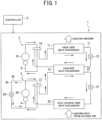
- FIG. 1 is a refrigeration circuit diagram of a cascade refrigeration system according to a first embodiment of the present invention.
- FIG. 2 is a control flow diagram of the cascade refrigeration system according to the first embodiment of the present invention.
- the cascade refrigeration system 1 is a refrigeration system usable for an operation of making high-temperature hot water or for a heating operation on a high-temperature side.
- the hot water making operation and the heating operation are sometimes collectively referred to as a heating operation.
- This embodiment describes a cascade refrigeration system used for the heating operation.
- the cascade refrigeration system 1 includes a high-side refrigerant circuit 2, a low-side refrigerant circuit 3, and a controller 5, in which the controller 5 controls the cascade refrigeration system 1.
- the high-side refrigerant circuit 2 has a high-side first circulation path 17.
- the high-side first circulation path 17 contains a high-side compressor 10, a high-side heat exchanger 11 exchanging heat with a heating medium, such as air or water, a high-side expansion valve 12 as a high-side expansion mechanism, and a cascade heat exchanger 13 sequentially connected by a refrigerant pipe 6, the high-side first circulation path 17 through which a high-side refrigerant circulates.
- the cascade heat exchanger 13 is a heat exchanger where the high-side refrigerant flowing through the high-side refrigerant circuit 2 and a low-side refrigerant flowing through the low-side refrigerant circuit 3 exchange heat.
- the high-side heat exchanger 11 is a heat exchanger exchanging heat with the high-side refrigerant and air as the heating medium through a ventilator (not illustrated).
- the high-side heat exchanger 11 is a heat exchanger where the high-side refrigerant and the air as the heating medium exchange heat, but may also be a heat exchanger exchanging heat with water as a heating medium flowing through a heating medium circuit (not illustrated), for example.
- the arrows in the high-side refrigerant circuit 2 indicate the flow of the high-side refrigerant in the heating operation.
- a high-side four-way valve 14 is connected to a discharge side of the high-side compressor 10, the high-side four-way valve 14 which switches the flow of the high-side refrigerant discharged from the high-side compressor 10 between the flow to the side of the high-side heat exchanger 11 and the flow to the side of the cascade heat exchanger 13.
- This embodiment describes a case where the high-side four-way valve 14 sends the high-side refrigerant discharged from the high-side compressor 10 to the side of the high-side heat exchanger 11 (heating operation).
- the high-side refrigerant discharged from the high-side compressor 10 flows through the high-side heat exchanger 11, the high-side expansion valve 12, and the cascade heat exchanger 13 to be sucked into the high-side compressor 10.
- the low-side refrigerant circuit 3 has a low-side first circulation path 23 and a low-side second circulation path 28.
- the low-side first circulation path 23 contains a low-side compressor 20, the cascade heat exchanger 13 connected to the high-side refrigerant circuit 2, a low-side expansion valve 21 as a low-side expansion mechanism, and a heat source-side heat exchanger 22 absorbing heat from the outside air sequentially connected by the refrigerant pipe 6, the low-side first circulation path 23 through which the low-side refrigerant circulates.
- the cascade heat exchanger 13 is a heat exchanger where the low-side refrigerant and the high-side refrigerant flowing through the high-side refrigerant circuit 2 exchange heat.
- the arrows in the low-side refrigerant circuit 3 indicate the flow of the low-side refrigerant.
- the low-side refrigerant circuit 3 has a low-side bypass path 25 connecting a discharge side of the low-side compressor 20 and a suction side of the low-side compressor 20.
- the low-side bypass path 25 is provided with a low-side opening and closing valve 26.
- the low-side opening and closing valve 26 opens and closes the low-side bypass path 25.
- a flow path where the low-side refrigerant circulates from the discharge side of the low-side compressor 20 to the suction side of the low-side compressor 20 through the low-side bypass path 25 serves as the low-side second circulation path 28.
- the low-side opening and closing valve 26 When the low-side opening and closing valve 26 is closed, the low-side refrigerant circulates through the low-side first circulation path 23.
- the low-side opening and closing valve 26 serves as a low-side switching device switching the circulation of the low-side refrigerant discharged from the low-side compressor 20 between the circulation to the low-side first circulation path 23 and the circulation to the low-side second circulation path 28 in the present invention.
- This embodiment uses the low-side opening and closing valve 26, which is an opening and closing valve, as the low-side switching device.
- the other device may be used as the low-side switching device.
- a three-way valve is provided at one end or the other end of the low-side bypass path 25 and the three-way valve switches the circulation of the low-side refrigerant discharged from the low-side compressor 20 between the circulation to the low-side first circulation path 23 and the circulation to the low-side second circulation path 28.
- a low-side four-way valve 27 is connected to the discharge side of the low-side compressor 20, the low-side four-way valve 27 which switches the flow of the low-side refrigerant discharged from the low-side compressor 20 between the flow to the side of the cascade heat exchanger 13 and the flow to the heat source-side heat exchanger 22.
- This embodiment describes a case where the low-side four-way valve 27 sends the low-side refrigerant discharged from the low-side compressor 20 to the side of the cascade heat exchanger 13 (heating operation).
- the low-side refrigerant discharged from the low-side compressor 20 flows through the cascade heat exchanger 13, the low-side expansion valve 21, and the heat source-side heat exchanger 22 to be sucked into the low-side compressor 20.
- the low-side compressor 20 is a configuration commonly used in the low-side first circulation path 23 and the low-side second circulation path 28.
- the high-side refrigerant in the high-side refrigerant circuit 2 and the low-side refrigerant in the low-side refrigerant circuit 3 are the same refrigerant, but are not necessarily required to be the same, and a low-side refrigerant having a lower boiling point than that of a high-side refrigerant may be acceptable, for example .
- the controller 5 When the cascade refrigeration system 1 is activated, the controller 5 first activates the high-side compressor 10 (ST1), and then activates the low-side compressor 20 (ST2) . More specifically, the high-side compressor 10 and the low-side compressor 20 are almost simultaneously activated. Next, the low-side opening and closing valve 26 is opened (ST3) . By opening the low-side opening and closing valve 26, most of the low-side refrigerants at high temperatures and high pressures discharged from the low-side compressor 20 flow to the suction side of the low-side compressor 20 through the low-side bypass path 25 smaller in flow resistance than the low-side first circulation path 23.
- the low-side refrigerant at a high temperature and a high pressure discharged from the low-side compressor 20 circulates through the low-side second circulation path 28.
- the temperature of the high-side refrigerant is detected by a temperature sensor (not illustrated) provided in a pipe connected to the discharge side of the high-side compressor 10.
- the temperature of the heating medium is detected by a temperature sensor (not illustrated) provided at a position where the temperature of the heating medium flowing into the high-side heat exchanger 11 is detected.
- the cascade refrigeration system 1 of the first embodiment is characterized by the fact that the high-side compressor 10 is activated (ST1), the low-side compressor 20 is activated (ST2), the low-side opening and closing valve 26 is opened, and then the low-side refrigerant at a high temperature and a high pressure discharged from the low-side compressor 20 circulates through the low-side second circulation path 28. More specifically, most of the low-side refrigerants at high temperatures and high pressures discharged from the low-side compressor 20 circulate to the suction side of the low-side compressor 20 through the low-side bypass path 25 smaller in flow resistance than the low-side first circulation path 23.
- a cascade refrigeration system 50 as a second embodiment is described with reference to FIG. 3 .
- a difference between the cascade refrigeration system 50 of the second embodiment and the cascade refrigeration system 1 of the first embodiment is that the high-side refrigerant circuit 2 is provided with a high-side second circulation path 18 and the low-side refrigerant circuit 3 is not provided with the low-side second circulation path 28, and the other configurations are common.
- the same reference numerals are used for the common configurations.
- FIG. 3 is a refrigerant circuit diagram of the cascade refrigeration system 50 of the second embodiment.
- the cascade refrigeration system 50 is a refrigeration system usable for the heating operation on the high temperature side.
- This embodiment describes a cascade refrigeration system used for the heating operation.
- the cascade refrigeration system 50 includes the high-side refrigerant circuit 2, the low-side refrigerant circuit 3, and the controller 5, in which the controller 5 controls the cascade refrigeration system 50.
- the high-side refrigerant circuit 2 has the high-side first circulation path 17 and the high-side second circulation path 18.
- the high-side first circulation path 17 contains the high-side compressor 10, the high-side heat exchanger 11 exchanging heat with the heating medium, such as air or water, the high-side expansion valve 12 as the high-side expansion mechanism, and the cascade heat exchanger 13 sequentially connected by the refrigerant pipe 6, the high-side first circulation path 17 through which the high-side refrigerant circulates.
- the cascade heat exchanger 13 is a heat exchanger where the high-side refrigerant flowing through the high-side refrigerant circuit 2 and the low-side refrigerant flowing through the low-side refrigerant circuit 3 exchange heat.
- the high-side heat exchanger 11 is a heat exchanger exchanging heat with the high-side refrigerant and air as a heating medium through a ventilator (not illustrated) .
- the high-side heat exchanger 11 is a heat exchanger where the high-side refrigerant and the air as the heating medium exchange heat, but may also be a heat exchanger exchanging heat with water as a heating medium flowing through a heating medium circuit (not illustrated), for example.
- the arrows in the high-side refrigerant circuit 2 indicate the flow of the high-side refrigerant (heating operation).
- the high-side refrigerant circuit 2 includes a high-side bypass path 15 connecting the discharge side of the high-side compressor 10 and a suction side of the high-side compressor 10.
- the high-side bypass path 15 is provided with a high-side opening and closing valve 16.
- the high-side opening and closing valve 16 opens and closes the high-side bypass path 15.
- a flow path where the high-side refrigerant circulates from the discharge side of the high-side compressor 10 to the suction side of the high-side compressor 10 through the high-side bypass path 15 serves as the high-side second circulation path 18.
- the high-side opening and closing valve 16 When the high-side opening and closing valve 16 is closed, the high-side refrigerant circulates through the high-side first circulation path 17.
- the high-side opening and closing valve 16 serves as a high-side switching device switching the circulation of the high-side refrigerant discharged from the high-side compressor 10 between the circulation to the high-side first circulation path 17 and the circulation to the high-side second circulation path 18 in the present invention.
- This embodiment uses the high-side opening and closing valve 16, which is an opening and closing valve, as the high-side switching device.
- the other device may be used as the high-side switching device.
- a three-way valve is provided at one end or the other end of the high-side bypass path 15 and the three-way valve switches the circulation of the high-side refrigerant discharged from the high-side compressor 10 between the circulation to the high-side first circulation path 17 and the circulation to the high-side second circulation path 18.
- a high-side four-way valve 14 is connected to the discharge side of the high-side compressor 10, the high-side four-way valve 14 which switches the flow of the high-side refrigerant discharged from the high-side compressor 10 between the flow to the side of the high-side heat exchanger 11 and the flow to the side of the cascade heat exchanger 13.
- This embodiment describes a case where the high-side four-way valve 14 sends the high-side refrigerant discharged from the high-side compressor 10 to the side of the high-side heat exchanger 11.
- the high-side refrigerant discharged from the high-side compressor 10 flows through the high-side heat exchanger 11, the high-side expansion valve 12, and the cascade heat exchanger 13 to be sucked into the high-side compressor 10.
- the high-side compressor 10 is a configuration commonly used in the high-side first circulation path 17 and the high-side second circulation path 18.
- the low-side refrigerant circuit 3 has the low-side first circulation path 23.
- the low-side first circulation path 23 contains a low-side compressor 20, the cascade heat exchanger 13 connected to the high-side refrigerant circuit 2, a low-side expansion valve 21 as a low-side expansion mechanism, and a heat source-side heat exchanger 22 absorbing heat from the outside air sequentially connected by the refrigerant pipe 6, the low-side first circulation path 23 through which the low-side refrigerant circulates.
- the cascade heat exchanger 13 is a heat exchanger where the low-side refrigerant and the high-side refrigerant flowing through the high-side refrigerant circuit 2 exchange heat.
- the arrows in the low-side refrigerant circuit 3 indicate the flow of the low-side refrigerant.
- the low-side four-way valve 27 is connected to the discharge side of the low-side compressor 20, the low-side four-way valve 27 which switches the flow of the low-side refrigerant discharged from the low-side compressor 20 between the flow to the side of the cascade heat exchanger 13 and the flow to the heat source-side heat exchanger 22.
- This embodiment describes a case where the low-side four-way valve 27 sends the low-side refrigerant discharged from the low-side compressor 20 to the side of the cascade heat exchanger 13.
- the low-side refrigerant discharged from the low-side compressor 20 flows through the cascade heat exchanger 13, the low-side expansion valve 21, and the heat source-side heat exchanger 22 to be sucked into the low-side compressor 20.
- the high-side refrigerant in the high-side refrigerant circuit 2 and the low-side refrigerant in the low-side refrigerant circuit 3 are the same refrigerant, but are not necessarily required to be the same, and a low-side refrigerant having a lower boiling point than that of a high-side refrigerant may be acceptable, for example.
- the controller 5 first activates the high-side compressor 10 (ST10).
- the high-side opening and closing valve 16 is opened (ST11).
- ST11 By opening the high-side opening and closing valve 16, most of the high-side refrigerants at high temperatures and high pressures discharged from the high-side compressor 10 circulate to the suction side of the high-side compressor 10 through the high-side bypass path 15 smaller in flow resistance than the high-side first circulation path 17. More specifically, the high-side refrigerant at a high temperature and a high pressure discharged from the high-side compressor 10 circulates through the high-side second circulation path 18. Next, it is determined whether the temperature of the high-side compressor 10 exceeds 60°C which is a predetermined value (ST12).
- the temperature of the high-side compressor 10 is detected by a temperature sensor (not illustrated) provided in a pipe connected to the discharge side of the high-side compressor 10.
- the predetermined value is such a value that, when the temperature of the high-side compressor 10 is equal to or larger than the value, a desired heat exchange amount with the heating medium is obtained in the high-side heat exchanger 11, and, when the temperature is reached, the high-side refrigerant can be sufficiently condensed in the high-side heat exchanger 11.
- the temperature of the high-side compressor 10 exceeds 60°C which is the predetermined value (Yes in ST12)
- the high-side opening and closing valve 16 is closed (ST13) .
- the operation is continued.
- the temperature of the heating medium is detected by a temperature sensor (not illustrated) provided at a position where the temperature of the heating medium flowing into the high-side heat exchanger 11 is detected.
- the low-side compressor 20 is activated (ST15).
- the cascade refrigeration system 1 of this embodiment is characterized by the fact that the high-side compressor 10 is activated (ST10), the high-side opening and closing valve 16 is opened, and then the high-side refrigerant at a high temperature and a high pressure discharged from the high-side compressor 10 circulates through the high-side second circulation path 18. More specifically, most of the high-side refrigerants at high temperatures and high pressures discharged from the high-side compressor 10 circulate to the suction side of the high-side compressor 10 through the high-side bypass path 15 smaller in flow resistance than the high-side first circulation path 17. This makes it possible to immediately raise the temperature of the high-side compressor 10 and suppress a stagnation operation when the outside air temperature is low.
- a cascade refrigeration system 51 as a third embodiment is described with reference to FIG. 5 .
- a difference between the cascade refrigeration system 51 of the third embodiment and the cascade refrigeration system 1 of the first embodiment is that the high-side refrigerant circuit 2 is provided with the high-side second circulation path 18 and the low-side refrigerant circuit 3 is provided with the low-side second circulation path 28, and the other configurations are common.
- the same reference numerals are used for the common configurations.
- FIG. 5 is a refrigerant circuit diagram of the cascade refrigeration system 51 of the third embodiment.
- the cascade refrigeration system 51 is a refrigeration system usable for storing frozen food or other items when used on the low temperature side, and usable for making high-temperature hot water or usable for the heating operation when used on the high temperature side.
- This embodiment describes a cascade refrigeration system used for the heating operation.
- the cascade refrigeration system 51 includes the high-side refrigerant circuit 2, the low-side refrigerant circuit 3, and the controller 5, in which the controller 5 controls the cascade refrigeration system 51.
- the high-side refrigerant circuit 2 has the high-side first circulation path 17 and the high-side second circulation path 18.
- the high-side first circulation path 17 contains the high-side compressor 10, the high-side heat exchanger 11 exchanging heat with the heating medium, such as air or water, the high-side expansion valve 12 as the high-side expansion mechanism, and the cascade heat exchanger 13 sequentially connected by the refrigerant pipe 6, the high-side first circulation path 17 through which the high-side refrigerant circulates.
- the cascade heat exchanger 13 is a heat exchanger where the high-side refrigerant flowing through the high-side refrigerant circuit 2 and the low-side refrigerant flowing through the low-side refrigerant circuit 3 exchange heat.
- the high-side heat exchanger 11 is a heat exchanger exchanging heat with the high-side refrigerant and the air as the heating medium through a ventilator (not illustrated).
- the high-side heat exchanger 11 is a heat exchanger where the high-side refrigerant and the air as the heating medium exchange heat, but may also be a heat exchanger exchanging heat with water as a heating medium flowing through a heating medium circuit (not illustrated), for example.
- the arrows in the high-side refrigerant circuit 2 indicate the flow of the high-side refrigerant (heating operation).
- the high-side refrigerant circuit 2 includes the high-side bypass path 15 connecting the discharge side of the high-side compressor 10 and the suction side of the high-side compressor 10.
- the high-side bypass path 15 is provided with the high-side opening and closing valve 16.
- the high-side opening and closing valve 16 opens and closes the high-side bypass path 15.
- a flow path where the high-side refrigerant circulates from the discharge side of the high-side compressor 10 to the suction side of the high-side compressor 10 through the high-side bypass path 15 serves as the high-side second circulation path 18.
- the high-side opening and closing valve 16 When the high-side opening and closing valve 16 is closed, the high-side refrigerant circulates through the high-side first circulation path 17.
- the high-side opening and closing valve 16 serves as the high-side switching device switching the circulation of the high-side refrigerant discharged from the high-side compressor 10 between the circulation to the high-side first circulation path 17 and the circulation to the high-side second circulation path 18 in the present invention.
- This embodiment uses the high-side opening and closing valve 16, which is an opening and closing valve, as the high-side switching device.
- the other device may be used as the high-side switching device.
- a three-way valve is provided at one end or the other end of the high-side bypass path 15 and the three-way valve switches the circulation of the high-side refrigerant discharged from the high-side compressor 10 between the circulation to the high-side first circulation path 17 and the circulation to the high-side second circulation path 18.
- the high-side four-way valve 14 is connected to the discharge side of the high-side compressor 10, the high-side four-way valve 14 which switches the flow of the high-side refrigerant discharged from the high-side compressor 10 between the flow to the side of the high-side heat exchanger 11 and the flow to the side of the cascade heat exchanger 13.
- This embodiment describes a case where the high-side four-way valve 14 sends the high-side refrigerant discharged from the high-side compressor 10 to the side of the high-side heat exchanger 11.
- the high-side refrigerant discharged from the high-side compressor 10 flows through the high-side heat exchanger 11, the high-side expansion valve 12, and the cascade heat exchanger 13 to be sucked into the high-side compressor 10.
- the high-side compressor 10 is a configuration commonly used in the high-side first circulation path 17 and the high-side second circulation path 18.
- the low-side refrigerant circuit 3 has the low-side first circulation path 23 and the low-side second circulation path 28.
- the low-side first circulation path 23 contains the low-side compressor 20, the cascade heat exchanger 13 connected to the high-side refrigerant circuit 2, the low-side expansion valve 21 as the low-side expansion mechanism, and the heat source-side heat exchanger 22 absorbing heat from the outside air sequentially connected by the refrigerant pipe 6, the low-side first circulation path 23 through which the low-side refrigerant circulates.
- the cascade heat exchanger 13 is a heat exchanger where the low-side refrigerant and the high-side refrigerant flowing through the high-side refrigerant circuit 2 exchange heat.
- the arrows in the low-side refrigerant circuit 3 indicate the flow of the low-side refrigerant.
- the low-side refrigerant circuit 3 has the low-side bypass path 25 connecting the discharge side of the low-side compressor 20 and the suction side of the low-side compressor 20.
- the low-side bypass path 25 is provided with the low-side opening and closing valve 26.
- the low-side opening and closing valve 26 opens and closes the low-side bypass path 25.
- a flow path where the low-side refrigerant circulates from the discharge side of the low-side compressor 20 to the suction side of the low-side compressor 20 through the low-side bypass path 25 serves as the low-side second circulation path 28.
- the low-side opening and closing valve 26 When the low-side opening and closing valve 26 is closed, the low-side refrigerant circulates through the low-side first circulation path 23.
- the low-side opening and closing valve 26 serves as the low-side switching device switching the circulation of the low-side refrigerant discharged from the low-side compressor 20 between the circulation to the low-side first circulation path 23 and the circulation to the low-side second circulation path 28 in the present invention.
- This embodiment uses the low-side opening and closing valve 26, which is an opening and closing valve, as the low-side switching device.
- the other device may be used as the low-side switching device.
- a three-way valve is provided at one end or the other end of the low-side bypass path 25 and the three-way valve switches the circulation of the low-side refrigerant discharged from the low-side compressor 20 between the circulation to the low-side first circulation path 23 and the circulation to the low-side second circulation path 28.
- the low-side four-way valve 27 is connected to the discharge side of the low-side compressor 20, the low-side four-way valve 27 which switches the flow of the low-side refrigerant discharged from the low-side compressor 20 between the flow to the side of the cascade heat exchanger 13 and the flow to the heat source-side heat exchanger 22.
- This embodiment describes a case where the low-side four-way valve 27 sends the low-side refrigerant discharged from the low-side compressor 20 to the side of the cascade heat exchanger 13.
- the low-side refrigerant discharged from the low-side compressor 20 flows through the cascade heat exchanger 13, the low-side expansion valve 21, and the heat source-side heat exchanger 22 to be sucked into the low-side compressor 20.
- the low-side compressor 20 is a configuration commonly used in the low-side first circulation path 23 and the low-side second circulation path 28.
- the high-side refrigerant in the high-side refrigerant circuit 2 and the low-side refrigerant in the low-side refrigerant circuit 3 are the same refrigerant, but are not necessarily required to be the same, and a low-side refrigerant having a lower boiling point than that of a high-side refrigerant may be acceptable, for example.
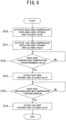
- the controller 5 When the cascade refrigeration system 51 is activated, the controller 5 first activates the high-side compressor 10, and then opens the high-side opening and closing valve 16 (ST20). By opening the high-side opening and closing valve 16, most of the high-side refrigerants at high temperatures and high pressures discharged from the high-side compressor 10 circulate to the suction side of the high-side compressor 10 through the high-side bypass path 15 smaller in flow resistance than the high-side first circulation path 17. More specifically, the high-side refrigerant at a high temperature and a high pressure discharged from the high-side compressor 10 circulates through the high-side second circulation path 18. Next, the low-side compressor 20 is activated, and then the low-side opening and closing valve 26 is opened (ST21).
- the low-side opening and closing valve 26 By opening the low-side opening and closing valve 26, most of the low-side refrigerants at high temperatures and high pressures discharged from the low-side compressor 20 circulate to the suction side of the low-side compressor 20 through the low-side bypass path 25 smaller in flow resistance than the low-side first circulation path 23. More specifically, the low-side refrigerant at a high temperature and a high pressure discharged from the low-side compressor 20 circulates through the low-side second circulation path 28. Next, it is determined whether the temperature of the high-side compressor 10 exceeds 60°C which is the predetermined value (ST22). The temperature of the high-side compressor 10 is detected by a temperature sensor (not illustrated) provided in a pipe connected to the discharge side of the high-side compressor 10.
- the predetermined value is such a value that a desired heat exchange amount with the heating medium is obtained in the high-side heat exchanger 11, and, when the temperature is reached, the high-side refrigerant can be sufficiently condensed in the high-side heat exchanger 11.
- the temperature of the high-side refrigerant discharged from the high-side compressor 10 of the high-side refrigerant circuit 2 is higher than the temperature of the air as the heating medium exchanging heat in the high-side heat exchanger 11 (ST24).
- the temperature of the heating medium is detected by a temperature sensor (not illustrated) provided at a position where the temperature of the heating medium flowing into the high-side heat exchanger 11 is detected.
- the low-side opening and closing valve 26 is closed (ST25).
- the cascade refrigeration system 51 of this embodiment is characterized that the high-side compressor 10 is activated and the high-side opening and closing valve 16 is opened, and the low-side compressor 20 is activated and the low-side opening and closing valve 26 is opened, the high-side refrigerant at a high temperature and a high pressure discharged from the high-side compressor 10 circulates through the high-side second circulation path 18, and the low-side refrigerant at a high temperature and a high pressure discharged from the low-side compressor 20 circulates through the low-side second circulation path 28.
- the high-side refrigerant can exchange heat with the air which is the heating medium in the high-side heat exchanger 11, and thus can be condensed.
- This enables the high-side refrigerant to exchange heat with the low-side refrigerant in the cascade heat exchanger 13, which makes it possible to promptly start the activation of the low-side compressor 20.
- a rise in the high-pressure side of the low-side refrigerant in the low-side refrigerant circuit 3 can be suppressed. Accordingly, even when the high-side refrigerant is unable to evaporate in the cascade heat exchanger 13 of the high-side refrigerant circuit 2, the operation of the low-side compressor 20 can be continued. Further, by immediately warming the low-side compressor 20, stagnation when the outside air is low can be suppressed.
Landscapes
- Engineering & Computer Science (AREA)
- Physics & Mathematics (AREA)
- Mechanical Engineering (AREA)
- Thermal Sciences (AREA)
- General Engineering & Computer Science (AREA)
- Compression-Type Refrigeration Machines With Reversible Cycles (AREA)
- Applications Or Details Of Rotary Compressors (AREA)
Abstract
Description
- The present invention relates to a cascade refrigeration system, and particularly relates to a cascade refrigeration system that enables a smooth start-up to a steady-state operation.
- A conventional cascade refrigeration system includes a high-side refrigerant circuit in which a compressor, a condenser, an expansion mechanism, and an evaporation unit of an intermediate heat exchanger are sequentially connected and through which a high-side refrigerant circulates and a low-side refrigerant circuit in which a compressor, a condensing unit of an intermediate heat exchanger, an expansion mechanism, and an evaporator are sequentially connected, through which a low-side refrigerant circulates, and in which the high-side refrigerant and the low-side refrigerant exchange heat in the intermediate heat exchanger. Such a cascade refrigeration system can dissipate heat in the condenser of the high-side refrigerant circuit or obtain a cold source of a refrigerator in the evaporator of the low-side refrigerant circuit.
- In such a cascade refrigeration system, when the low-side refrigerant circuit and the high-side refrigerant circuit are simultaneously activated, the refrigerant is not condensed in the condenser until the discharge temperature sufficiently rises, and therefore the refrigerant circulation amount cannot be sufficiently ensured in the high-side refrigerant circuit, sometimes leading to a low-pressure cutoff of the high-side refrigerant circuit. Further, the low-side refrigerant circuit is activated in a state where the refrigerant circulation amount of the high-side refrigerant circuit cannot be sufficiently ensured. Therefore, the low-side refrigerant of the low-side refrigerant circuit does not sufficiently exchange heat with the high-side refrigerant in the intermediate heat exchanger, sometimes leading to a high-pressure cutoff of the low-side refrigerant circuit. The conventional cascade refrigeration system has had a high risk that in any case results in an abnormal stop before a steady-state operation is achieved.
- Therefore, in the cascade refrigeration system disclosed in PTL 1, when the low-side refrigerant reaches a predetermined first pressure after the low-side refrigerant circuit is activated, the low-side refrigerant circuit is stopped and the high-side refrigerant circuit is activated. Then, when the low-side refrigerant of the low-side refrigerant circuit is depressurized to a prescribed second pressure, the low-side refrigerant circuit is activated. Therefore, in the start-up, there is no risk of causing either a high-pressure abnormality of the low-side refrigerant circuit or a low-pressure abnormality of the high-side refrigerant circuit, thus enabling a smooth start-up to a steady-state operation.
- PTL 1:
JP 2013-213592 A - However, the cascade refrigeration system disclosed in PTL 1 alternately operates the compressor of the low-side refrigerant circuit and the compressor of the high-side refrigerant circuit, and therefore requires time for the start-up and undergoes a decrease in reliability of the compressors. Further, the cascade refrigeration system disclosed in PTL 1 has a problem of an increase in power consumption due to repeated activation and stop of the compressors.
- In view of the above-described problem, it is an object of the present invention to provide a cascade refrigeration system capable of promptly performing a start-up operation, and suppressing the decrease in reliability of the compressor and suppressing the increase in power consumption in the cascade refrigeration system.
- One aspect of the present invention is a cascade refrigeration system including: a high-side refrigerant circuit containing a high-side compressor, a high-side heat exchanger configured to exchange heat with a heating medium, a high-side expansion mechanism, and a cascade heat exchanger sequentially connected by a refrigerant pipe and having a high-side first circulation path through which a high-side refrigerant circulates; a low-side refrigerant circuit containing a low-side compressor, the cascade heat exchanger, a low-side expansion mechanism, and a heat source-side heat exchanger sequentially connected by a refrigerant pipe, the low-side refrigerant circuit through which a low-side refrigerant circulates; and a controller configured to control the high-side refrigerant circuit and the low-side refrigerant circuit, in which the high-side refrigerant and the low-side refrigerant exchange heat in the cascade heat exchanger, and the high-side refrigerant circuit includes: a high-side second circulation path in which a discharge side and a suction side of the high-side compressor are connected by a high-side bypass path and the high-side refrigerant discharged from the high-side compressor circulates to the suction side of the high-side compressor through the high-side bypass path; and a high-side switching device configured to switch a circulation path such that the high-side refrigerant discharged from the high-side compressor circulates through the high-side first circulation path or the high-side second circulation path.
- The present invention can provide a cascade refrigeration system capable of promptly performing a start-up operation, and suppressing the decrease in reliability of the compressor and suppressing the increase in power consumption in the cascade refrigeration system.
-
-
FIG. 1 is a refrigeration circuit diagram of a cascade refrigeration system according to a first embodiment of the present invention; -
FIG. 2 is a control flow diagram of the cascade refrigeration system according to the first embodiment of the present invention; -
FIG. 3 is a refrigeration circuit diagram of a cascade refrigeration system according to a second embodiment of the present invention; -
FIG. 4 is a control flow diagram of the cascade refrigeration system according to the second embodiment of the present invention; -
FIG. 5 is a refrigeration circuit diagram of a cascade refrigeration system according to a third embodiment of the present invention; and -
FIG. 6 is a control flow diagram of the cascade refrigeration system according to the third embodiment of the present invention. - Hereinafter, embodiments of a cascade refrigeration system according to the present invention are described in detail based on the drawings. This invention is not limited by the embodiments.
-
FIG. 1 is a refrigeration circuit diagram of a cascade refrigeration system according to a first embodiment of the present invention.FIG. 2 is a control flow diagram of the cascade refrigeration system according to the first embodiment of the present invention. - A cascade refrigeration system 1, which is a first embodiment, is described with reference to
FIG. 1 . The cascade refrigeration system 1 is a refrigeration system usable for an operation of making high-temperature hot water or for a heating operation on a high-temperature side. Hereinafter, the hot water making operation and the heating operation are sometimes collectively referred to as a heating operation. This embodiment describes a cascade refrigeration system used for the heating operation. The cascade refrigeration system 1 includes a high-side refrigerant circuit 2, a low-side refrigerant circuit 3, and acontroller 5, in which thecontroller 5 controls the cascade refrigeration system 1. - The high-
side refrigerant circuit 2 has a high-sidefirst circulation path 17. The high-sidefirst circulation path 17 contains a high-side compressor 10, a high-side heat exchanger 11 exchanging heat with a heating medium, such as air or water, a high-side expansion valve 12 as a high-side expansion mechanism, and acascade heat exchanger 13 sequentially connected by arefrigerant pipe 6, the high-sidefirst circulation path 17 through which a high-side refrigerant circulates. Thecascade heat exchanger 13 is a heat exchanger where the high-side refrigerant flowing through the high-side refrigerant circuit 2 and a low-side refrigerant flowing through the low-side refrigerant circuit 3 exchange heat. In this embodiment, the high-side heat exchanger 11 is a heat exchanger exchanging heat with the high-side refrigerant and air as the heating medium through a ventilator (not illustrated). The high-side heat exchanger 11 is a heat exchanger where the high-side refrigerant and the air as the heating medium exchange heat, but may also be a heat exchanger exchanging heat with water as a heating medium flowing through a heating medium circuit (not illustrated), for example. The arrows in the high-side refrigerant circuit 2 indicate the flow of the high-side refrigerant in the heating operation. - In the high-
side refrigerant circuit 2, a high-side four-way valve 14 is connected to a discharge side of the high-side compressor 10, the high-side four-way valve 14 which switches the flow of the high-side refrigerant discharged from the high-side compressor 10 between the flow to the side of the high-side heat exchanger 11 and the flow to the side of thecascade heat exchanger 13. This embodiment describes a case where the high-side four-way valve 14 sends the high-side refrigerant discharged from the high-side compressor 10 to the side of the high-side heat exchanger 11 (heating operation). Accordingly, in the high-side refrigerant circuit 2, the high-side refrigerant discharged from the high-side compressor 10 flows through the high-side heat exchanger 11, the high-side expansion valve 12, and thecascade heat exchanger 13 to be sucked into the high-side compressor 10. - The low-
side refrigerant circuit 3 has a low-sidefirst circulation path 23 and a low-sidesecond circulation path 28. The low-sidefirst circulation path 23 contains a low-side compressor 20, thecascade heat exchanger 13 connected to the high-side refrigerant circuit 2, a low-side expansion valve 21 as a low-side expansion mechanism, and a heat source-side heat exchanger 22 absorbing heat from the outside air sequentially connected by therefrigerant pipe 6, the low-sidefirst circulation path 23 through which the low-side refrigerant circulates. Thecascade heat exchanger 13 is a heat exchanger where the low-side refrigerant and the high-side refrigerant flowing through the high-side refrigerant circuit 2 exchange heat. The arrows in the low-side refrigerant circuit 3 indicate the flow of the low-side refrigerant. - The low-
side refrigerant circuit 3 has a low-side bypass path 25 connecting a discharge side of the low-side compressor 20 and a suction side of the low-side compressor 20. The low-side bypass path 25 is provided with a low-side opening andclosing valve 26. The low-side opening andclosing valve 26 opens and closes the low-side bypass path 25. A flow path where the low-side refrigerant circulates from the discharge side of the low-side compressor 20 to the suction side of the low-side compressor 20 through the low-side bypass path 25 serves as the low-sidesecond circulation path 28. When the low-side opening andclosing valve 26 is closed, the low-side refrigerant circulates through the low-sidefirst circulation path 23. When the low-side opening andclosing valve 26 is opened, most of the low-side refrigerants circulate through the low-sidesecond circulation path 28 smaller in flow resistance than the low-sidefirst circulation path 23. The low-side opening andclosing valve 26 serves as a low-side switching device switching the circulation of the low-side refrigerant discharged from the low-side compressor 20 between the circulation to the low-sidefirst circulation path 23 and the circulation to the low-sidesecond circulation path 28 in the present invention. This embodiment uses the low-side opening andclosing valve 26, which is an opening and closing valve, as the low-side switching device. However, the other device may be used as the low-side switching device. For example, it may be acceptable that a three-way valve is provided at one end or the other end of the low-side bypass path 25 and the three-way valve switches the circulation of the low-side refrigerant discharged from the low-side compressor 20 between the circulation to the low-sidefirst circulation path 23 and the circulation to the low-sidesecond circulation path 28. - In the low-
side refrigerant circuit 3, a low-side four-way valve 27 is connected to the discharge side of the low-side compressor 20, the low-side four-way valve 27 which switches the flow of the low-side refrigerant discharged from the low-side compressor 20 between the flow to the side of thecascade heat exchanger 13 and the flow to the heat source-side heat exchanger 22. This embodiment describes a case where the low-side four-way valve 27 sends the low-side refrigerant discharged from the low-side compressor 20 to the side of the cascade heat exchanger 13 (heating operation). In this case, in the low-siderefrigerant circuit 3, the low-side refrigerant discharged from the low-side compressor 20 flows through thecascade heat exchanger 13, the low-side expansion valve 21, and the heat source-side heat exchanger 22 to be sucked into the low-side compressor 20. In the low-siderefrigerant circuit 3, the low-side compressor 20 is a configuration commonly used in the low-sidefirst circulation path 23 and the low-sidesecond circulation path 28. - In the first embodiment, the high-side refrigerant in the high-side
refrigerant circuit 2 and the low-side refrigerant in the low-siderefrigerant circuit 3 are the same refrigerant, but are not necessarily required to be the same, and a low-side refrigerant having a lower boiling point than that of a high-side refrigerant may be acceptable, for example . - Next, the control of the cascade refrigeration system 1 according to the first embodiment is described with reference to the control flow diagram illustrated in
FIG. 2 . - When the cascade refrigeration system 1 is activated, the
controller 5 first activates the high-side compressor 10 (ST1), and then activates the low-side compressor 20 (ST2) . More specifically, the high-side compressor 10 and the low-side compressor 20 are almost simultaneously activated. Next, the low-side opening and closingvalve 26 is opened (ST3) . By opening the low-side opening and closingvalve 26, most of the low-side refrigerants at high temperatures and high pressures discharged from the low-side compressor 20 flow to the suction side of the low-side compressor 20 through the low-side bypass path 25 smaller in flow resistance than the low-sidefirst circulation path 23. More specifically, the low-side refrigerant at a high temperature and a high pressure discharged from the low-side compressor 20 circulates through the low-sidesecond circulation path 28. Next, it is determined whether the temperature of the high-side refrigerant discharged from the high-side compressor 10 of the high-siderefrigerant circuit 2 is higher than the temperature of air as the heating medium exchanging heat in the high-side heat exchanger 11 (ST4). The temperature of the high-side refrigerant is detected by a temperature sensor (not illustrated) provided in a pipe connected to the discharge side of the high-side compressor 10. The temperature of the heating medium is detected by a temperature sensor (not illustrated) provided at a position where the temperature of the heating medium flowing into the high-side heat exchanger 11 is detected. When the temperature of the high-side refrigerant discharged from the high-side compressor 10 of the high-siderefrigerant circuit 2 is higher than the temperature of the air as the heating medium exchanging heat in the high-side heat exchanger 11 (Yes in ST4), the low-side opening and closingvalve 26 is closed (ST5) . - The cascade refrigeration system 1 of the first embodiment is characterized by the fact that the high-
side compressor 10 is activated (ST1), the low-side compressor 20 is activated (ST2), the low-side opening and closingvalve 26 is opened, and then the low-side refrigerant at a high temperature and a high pressure discharged from the low-side compressor 20 circulates through the low-sidesecond circulation path 28. More specifically, most of the low-side refrigerants at high temperatures and high pressures discharged from the low-side compressor 20 circulate to the suction side of the low-side compressor 20 through the low-side bypass path 25 smaller in flow resistance than the low-sidefirst circulation path 23. This reduces a difference between the pressure of the refrigerant discharged from the low-side compressor 20 and the pressure of the refrigerant suctioned into the low-side compressor 20. This makes it possible to suppress a rise in the pressure of the low-side refrigerant on the high-pressure side of the low-siderefrigerant circuit 3 and makes it possible to continue the operation of the low-side compressor 20 even when the high-side refrigerant is unable to evaporate in thecascade heat exchanger 13 of the high-siderefrigerant circuit 2. Further, by immediately warming the low-side compressor 20, stagnation when the outside air is low can be suppressed. - Next, a
cascade refrigeration system 50 as a second embodiment is described with reference toFIG. 3 . A difference between thecascade refrigeration system 50 of the second embodiment and the cascade refrigeration system 1 of the first embodiment is that the high-siderefrigerant circuit 2 is provided with a high-sidesecond circulation path 18 and the low-siderefrigerant circuit 3 is not provided with the low-sidesecond circulation path 28, and the other configurations are common. The same reference numerals are used for the common configurations. -
FIG. 3 is a refrigerant circuit diagram of thecascade refrigeration system 50 of the second embodiment. Thecascade refrigeration system 50 is a refrigeration system usable for the heating operation on the high temperature side. This embodiment describes a cascade refrigeration system used for the heating operation. Thecascade refrigeration system 50 includes the high-siderefrigerant circuit 2, the low-siderefrigerant circuit 3, and thecontroller 5, in which thecontroller 5 controls thecascade refrigeration system 50. - The high-side
refrigerant circuit 2 has the high-sidefirst circulation path 17 and the high-sidesecond circulation path 18. The high-sidefirst circulation path 17 contains the high-side compressor 10, the high-side heat exchanger 11 exchanging heat with the heating medium, such as air or water, the high-side expansion valve 12 as the high-side expansion mechanism, and thecascade heat exchanger 13 sequentially connected by therefrigerant pipe 6, the high-sidefirst circulation path 17 through which the high-side refrigerant circulates. Thecascade heat exchanger 13 is a heat exchanger where the high-side refrigerant flowing through the high-siderefrigerant circuit 2 and the low-side refrigerant flowing through the low-siderefrigerant circuit 3 exchange heat. In this embodiment, the high-side heat exchanger 11 is a heat exchanger exchanging heat with the high-side refrigerant and air as a heating medium through a ventilator (not illustrated) . The high-side heat exchanger 11 is a heat exchanger where the high-side refrigerant and the air as the heating medium exchange heat, but may also be a heat exchanger exchanging heat with water as a heating medium flowing through a heating medium circuit (not illustrated), for example. The arrows in the high-siderefrigerant circuit 2 indicate the flow of the high-side refrigerant (heating operation). - The high-side
refrigerant circuit 2 includes a high-side bypass path 15 connecting the discharge side of the high-side compressor 10 and a suction side of the high-side compressor 10. The high-side bypass path 15 is provided with a high-side opening and closingvalve 16. The high-side opening and closingvalve 16 opens and closes the high-side bypass path 15. A flow path where the high-side refrigerant circulates from the discharge side of the high-side compressor 10 to the suction side of the high-side compressor 10 through the high-side bypass path 15 serves as the high-sidesecond circulation path 18. When the high-side opening and closingvalve 16 is closed, the high-side refrigerant circulates through the high-sidefirst circulation path 17. When the high-side opening and closingvalve 16 is opened, most of the high-side refrigerants circulate through the high-sidesecond circulation path 18 smaller in flow resistance than the high-sidefirst circulation path 17. The high-side opening and closingvalve 16 serves as a high-side switching device switching the circulation of the high-side refrigerant discharged from the high-side compressor 10 between the circulation to the high-sidefirst circulation path 17 and the circulation to the high-sidesecond circulation path 18 in the present invention. This embodiment uses the high-side opening and closingvalve 16, which is an opening and closing valve, as the high-side switching device. However, the other device may be used as the high-side switching device. For example, it may be acceptable that a three-way valve is provided at one end or the other end of the high-side bypass path 15 and the three-way valve switches the circulation of the high-side refrigerant discharged from the high-side compressor 10 between the circulation to the high-sidefirst circulation path 17 and the circulation to the high-sidesecond circulation path 18. - In the high-side
refrigerant circuit 2, a high-side four-way valve 14 is connected to the discharge side of the high-side compressor 10, the high-side four-way valve 14 which switches the flow of the high-side refrigerant discharged from the high-side compressor 10 between the flow to the side of the high-side heat exchanger 11 and the flow to the side of thecascade heat exchanger 13. This embodiment describes a case where the high-side four-way valve 14 sends the high-side refrigerant discharged from the high-side compressor 10 to the side of the high-side heat exchanger 11. Accordingly, in the high-siderefrigerant circuit 2, the high-side refrigerant discharged from the high-side compressor 10 flows through the high-side heat exchanger 11, the high-side expansion valve 12, and thecascade heat exchanger 13 to be sucked into the high-side compressor 10. In the high-siderefrigerant circuit 2, the high-side compressor 10 is a configuration commonly used in the high-sidefirst circulation path 17 and the high-sidesecond circulation path 18. - The low-side
refrigerant circuit 3 has the low-sidefirst circulation path 23. The low-sidefirst circulation path 23 contains a low-side compressor 20, thecascade heat exchanger 13 connected to the high-siderefrigerant circuit 2, a low-side expansion valve 21 as a low-side expansion mechanism, and a heat source-side heat exchanger 22 absorbing heat from the outside air sequentially connected by therefrigerant pipe 6, the low-sidefirst circulation path 23 through which the low-side refrigerant circulates. Thecascade heat exchanger 13 is a heat exchanger where the low-side refrigerant and the high-side refrigerant flowing through the high-siderefrigerant circuit 2 exchange heat. The arrows in the low-siderefrigerant circuit 3 indicate the flow of the low-side refrigerant. - In the low-side
refrigerant circuit 3, the low-side four-way valve 27 is connected to the discharge side of the low-side compressor 20, the low-side four-way valve 27 which switches the flow of the low-side refrigerant discharged from the low-side compressor 20 between the flow to the side of thecascade heat exchanger 13 and the flow to the heat source-side heat exchanger 22. This embodiment describes a case where the low-side four-way valve 27 sends the low-side refrigerant discharged from the low-side compressor 20 to the side of thecascade heat exchanger 13. Accordingly, in the low-siderefrigerant circuit 3, the low-side refrigerant discharged from the low-side compressor 20 flows through thecascade heat exchanger 13, the low-side expansion valve 21, and the heat source-side heat exchanger 22 to be sucked into the low-side compressor 20. - In this embodiment, the high-side refrigerant in the high-side
refrigerant circuit 2 and the low-side refrigerant in the low-siderefrigerant circuit 3 are the same refrigerant, but are not necessarily required to be the same, and a low-side refrigerant having a lower boiling point than that of a high-side refrigerant may be acceptable, for example. - Next, the control of the
cascade refrigeration system 50 according to the second embodiment is described with reference to the control flow diagram illustrated inFIG. 4 . - When the
cascade refrigeration system 50 is activated, thecontroller 5 first activates the high-side compressor 10 (ST10). Next, the high-side opening and closingvalve 16 is opened (ST11). By opening the high-side opening and closingvalve 16, most of the high-side refrigerants at high temperatures and high pressures discharged from the high-side compressor 10 circulate to the suction side of the high-side compressor 10 through the high-side bypass path 15 smaller in flow resistance than the high-sidefirst circulation path 17. More specifically, the high-side refrigerant at a high temperature and a high pressure discharged from the high-side compressor 10 circulates through the high-sidesecond circulation path 18. Next, it is determined whether the temperature of the high-side compressor 10 exceeds 60°C which is a predetermined value (ST12). The temperature of the high-side compressor 10 is detected by a temperature sensor (not illustrated) provided in a pipe connected to the discharge side of the high-side compressor 10. The predetermined value is such a value that, when the temperature of the high-side compressor 10 is equal to or larger than the value, a desired heat exchange amount with the heating medium is obtained in the high-side heat exchanger 11, and, when the temperature is reached, the high-side refrigerant can be sufficiently condensed in the high-side heat exchanger 11. When the temperature of the high-side compressor 10 exceeds 60°C which is the predetermined value (Yes in ST12), the high-side opening and closingvalve 16 is closed (ST13) . When the temperature of the high-side compressor 10 does not exceed 60°C which is the predetermined value (No in ST12), the operation is continued. Next, it is determined whether the temperature of the high-side refrigerant discharged from the high-side compressor 10 of the high-siderefrigerant circuit 2 is higher than the temperature of the air as the heating medium exchanging heat in the high-side heat exchanger 11 (ST14). The temperature of the heating medium is detected by a temperature sensor (not illustrated) provided at a position where the temperature of the heating medium flowing into the high-side heat exchanger 11 is detected. When the temperature of the high-side refrigerant discharged from the high-side compressor 10 of the high-siderefrigerant circuit 2 is higher than the temperature of the air as the heating medium exchanging heat in the high-side heat exchanger 11 (Yes in ST14), the low-side compressor 20 is activated (ST15). - The cascade refrigeration system 1 of this embodiment is characterized by the fact that the high-
side compressor 10 is activated (ST10), the high-side opening and closingvalve 16 is opened, and then the high-side refrigerant at a high temperature and a high pressure discharged from the high-side compressor 10 circulates through the high-sidesecond circulation path 18. More specifically, most of the high-side refrigerants at high temperatures and high pressures discharged from the high-side compressor 10 circulate to the suction side of the high-side compressor 10 through the high-side bypass path 15 smaller in flow resistance than the high-sidefirst circulation path 17. This makes it possible to immediately raise the temperature of the high-side compressor 10 and suppress a stagnation operation when the outside air temperature is low. Further, a state where the refrigerant pressure of the high-side refrigerant is easily raised can be achieved, and therefore the high-side refrigerant exchange heat with the air which is the heating medium in the high-side heat exchanger 11, and thus can be condensed. This enables the high-side refrigerant to exchange heat with the low-side refrigerant in thecascade heat exchanger 13, which makes it possible to promptly start the activation of the low-side compressor 20. - Next, a
cascade refrigeration system 51 as a third embodiment is described with reference toFIG. 5 . A difference between thecascade refrigeration system 51 of the third embodiment and the cascade refrigeration system 1 of the first embodiment is that the high-siderefrigerant circuit 2 is provided with the high-sidesecond circulation path 18 and the low-siderefrigerant circuit 3 is provided with the low-sidesecond circulation path 28, and the other configurations are common. The same reference numerals are used for the common configurations. -
FIG. 5 is a refrigerant circuit diagram of thecascade refrigeration system 51 of the third embodiment. Thecascade refrigeration system 51 is a refrigeration system usable for storing frozen food or other items when used on the low temperature side, and usable for making high-temperature hot water or usable for the heating operation when used on the high temperature side. This embodiment describes a cascade refrigeration system used for the heating operation. Thecascade refrigeration system 51 includes the high-siderefrigerant circuit 2, the low-siderefrigerant circuit 3, and thecontroller 5, in which thecontroller 5 controls thecascade refrigeration system 51. - The high-side
refrigerant circuit 2 has the high-sidefirst circulation path 17 and the high-sidesecond circulation path 18. The high-sidefirst circulation path 17 contains the high-side compressor 10, the high-side heat exchanger 11 exchanging heat with the heating medium, such as air or water, the high-side expansion valve 12 as the high-side expansion mechanism, and thecascade heat exchanger 13 sequentially connected by therefrigerant pipe 6, the high-sidefirst circulation path 17 through which the high-side refrigerant circulates. Thecascade heat exchanger 13 is a heat exchanger where the high-side refrigerant flowing through the high-siderefrigerant circuit 2 and the low-side refrigerant flowing through the low-siderefrigerant circuit 3 exchange heat. In this embodiment, the high-side heat exchanger 11 is a heat exchanger exchanging heat with the high-side refrigerant and the air as the heating medium through a ventilator (not illustrated). The high-side heat exchanger 11 is a heat exchanger where the high-side refrigerant and the air as the heating medium exchange heat, but may also be a heat exchanger exchanging heat with water as a heating medium flowing through a heating medium circuit (not illustrated), for example. The arrows in the high-siderefrigerant circuit 2 indicate the flow of the high-side refrigerant (heating operation). - The high-side
refrigerant circuit 2 includes the high-side bypass path 15 connecting the discharge side of the high-side compressor 10 and the suction side of the high-side compressor 10. The high-side bypass path 15 is provided with the high-side opening and closingvalve 16. The high-side opening and closingvalve 16 opens and closes the high-side bypass path 15. A flow path where the high-side refrigerant circulates from the discharge side of the high-side compressor 10 to the suction side of the high-side compressor 10 through the high-side bypass path 15 serves as the high-sidesecond circulation path 18. When the high-side opening and closingvalve 16 is closed, the high-side refrigerant circulates through the high-sidefirst circulation path 17. When the high-side opening and closingvalve 16 is opened, most of the high-side refrigerants circulate through the high-sidesecond circulation path 18 smaller in flow resistance than the high-sidefirst circulation path 17. The high-side opening and closingvalve 16 serves as the high-side switching device switching the circulation of the high-side refrigerant discharged from the high-side compressor 10 between the circulation to the high-sidefirst circulation path 17 and the circulation to the high-sidesecond circulation path 18 in the present invention. This embodiment uses the high-side opening and closingvalve 16, which is an opening and closing valve, as the high-side switching device. However, the other device may be used as the high-side switching device. For example, it may be acceptable that a three-way valve is provided at one end or the other end of the high-side bypass path 15 and the three-way valve switches the circulation of the high-side refrigerant discharged from the high-side compressor 10 between the circulation to the high-sidefirst circulation path 17 and the circulation to the high-sidesecond circulation path 18. - In the high-side
refrigerant circuit 2, the high-side four-way valve 14 is connected to the discharge side of the high-side compressor 10, the high-side four-way valve 14 which switches the flow of the high-side refrigerant discharged from the high-side compressor 10 between the flow to the side of the high-side heat exchanger 11 and the flow to the side of thecascade heat exchanger 13. This embodiment describes a case where the high-side four-way valve 14 sends the high-side refrigerant discharged from the high-side compressor 10 to the side of the high-side heat exchanger 11. Accordingly, in the high-siderefrigerant circuit 2, the high-side refrigerant discharged from the high-side compressor 10 flows through the high-side heat exchanger 11, the high-side expansion valve 12, and thecascade heat exchanger 13 to be sucked into the high-side compressor 10. In the high-siderefrigerant circuit 2, the high-side compressor 10 is a configuration commonly used in the high-sidefirst circulation path 17 and the high-sidesecond circulation path 18. - The low-side
refrigerant circuit 3 has the low-sidefirst circulation path 23 and the low-sidesecond circulation path 28. The low-sidefirst circulation path 23 contains the low-side compressor 20, thecascade heat exchanger 13 connected to the high-siderefrigerant circuit 2, the low-side expansion valve 21 as the low-side expansion mechanism, and the heat source-side heat exchanger 22 absorbing heat from the outside air sequentially connected by therefrigerant pipe 6, the low-sidefirst circulation path 23 through which the low-side refrigerant circulates. Thecascade heat exchanger 13 is a heat exchanger where the low-side refrigerant and the high-side refrigerant flowing through the high-siderefrigerant circuit 2 exchange heat. The arrows in the low-siderefrigerant circuit 3 indicate the flow of the low-side refrigerant. - The low-side
refrigerant circuit 3 has the low-side bypass path 25 connecting the discharge side of the low-side compressor 20 and the suction side of the low-side compressor 20. The low-side bypass path 25 is provided with the low-side opening and closingvalve 26. The low-side opening and closingvalve 26 opens and closes the low-side bypass path 25. A flow path where the low-side refrigerant circulates from the discharge side of the low-side compressor 20 to the suction side of the low-side compressor 20 through the low-side bypass path 25 serves as the low-sidesecond circulation path 28. When the low-side opening and closingvalve 26 is closed, the low-side refrigerant circulates through the low-sidefirst circulation path 23. When the low-side opening and closingvalve 26 is opened, most of the low-side refrigerants circulate through the low-sidesecond circulation path 28 smaller in flow resistance than the low-sidefirst circulation path 23. The low-side opening and closingvalve 26 serves as the low-side switching device switching the circulation of the low-side refrigerant discharged from the low-side compressor 20 between the circulation to the low-sidefirst circulation path 23 and the circulation to the low-sidesecond circulation path 28 in the present invention. This embodiment uses the low-side opening and closingvalve 26, which is an opening and closing valve, as the low-side switching device. However, the other device may be used as the low-side switching device. For example, it may be acceptable that a three-way valve is provided at one end or the other end of the low-side bypass path 25 and the three-way valve switches the circulation of the low-side refrigerant discharged from the low-side compressor 20 between the circulation to the low-sidefirst circulation path 23 and the circulation to the low-sidesecond circulation path 28. - In the low-side
refrigerant circuit 3, the low-side four-way valve 27 is connected to the discharge side of the low-side compressor 20, the low-side four-way valve 27 which switches the flow of the low-side refrigerant discharged from the low-side compressor 20 between the flow to the side of thecascade heat exchanger 13 and the flow to the heat source-side heat exchanger 22. This embodiment describes a case where the low-side four-way valve 27 sends the low-side refrigerant discharged from the low-side compressor 20 to the side of thecascade heat exchanger 13. Accordingly, in the low-siderefrigerant circuit 3, the low-side refrigerant discharged from the low-side compressor 20 flows through thecascade heat exchanger 13, the low-side expansion valve 21, and the heat source-side heat exchanger 22 to be sucked into the low-side compressor 20. In the low-siderefrigerant circuit 3, the low-side compressor 20 is a configuration commonly used in the low-sidefirst circulation path 23 and the low-sidesecond circulation path 28. - In this embodiment, the high-side refrigerant in the high-side
refrigerant circuit 2 and the low-side refrigerant in the low-siderefrigerant circuit 3 are the same refrigerant, but are not necessarily required to be the same, and a low-side refrigerant having a lower boiling point than that of a high-side refrigerant may be acceptable, for example. - Next, the control of the
cascade refrigeration system 51 according to the third embodiment is described with reference to the control flow diagram illustrated inFIG. 6 . - When the
cascade refrigeration system 51 is activated, thecontroller 5 first activates the high-side compressor 10, and then opens the high-side opening and closing valve 16 (ST20). By opening the high-side opening and closingvalve 16, most of the high-side refrigerants at high temperatures and high pressures discharged from the high-side compressor 10 circulate to the suction side of the high-side compressor 10 through the high-side bypass path 15 smaller in flow resistance than the high-sidefirst circulation path 17. More specifically, the high-side refrigerant at a high temperature and a high pressure discharged from the high-side compressor 10 circulates through the high-sidesecond circulation path 18. Next, the low-side compressor 20 is activated, and then the low-side opening and closingvalve 26 is opened (ST21). By opening the low-side opening and closingvalve 26, most of the low-side refrigerants at high temperatures and high pressures discharged from the low-side compressor 20 circulate to the suction side of the low-side compressor 20 through the low-side bypass path 25 smaller in flow resistance than the low-sidefirst circulation path 23. More specifically, the low-side refrigerant at a high temperature and a high pressure discharged from the low-side compressor 20 circulates through the low-sidesecond circulation path 28. Next, it is determined whether the temperature of the high-side compressor 10 exceeds 60°C which is the predetermined value (ST22). The temperature of the high-side compressor 10 is detected by a temperature sensor (not illustrated) provided in a pipe connected to the discharge side of the high-side compressor 10. The predetermined value is such a value that a desired heat exchange amount with the heating medium is obtained in the high-side heat exchanger 11, and, when the temperature is reached, the high-side refrigerant can be sufficiently condensed in the high-side heat exchanger 11. When the temperature of the high-side compressor 10 exceeds 60°C which is the predetermined value (Yes in ST22), the high-side opening and closingvalve 16 is closed (ST23). When the temperature of the high-side compressor 10 does not exceed 60°C which is the predetermined value (No in ST22), the operation is continued. Next, it is determined whether the temperature of the high-side refrigerant discharged from the high-side compressor 10 of the high-siderefrigerant circuit 2 is higher than the temperature of the air as the heating medium exchanging heat in the high-side heat exchanger 11 (ST24). The temperature of the heating medium is detected by a temperature sensor (not illustrated) provided at a position where the temperature of the heating medium flowing into the high-side heat exchanger 11 is detected. When the temperature of the high-side refrigerant discharged from the high-side compressor 10 of the high-siderefrigerant circuit 2 is higher than the temperature of the air as the heating medium exchanging heat in the high-side heat exchanger 11 (Yes in ST24), the low-side opening and closingvalve 26 is closed (ST25). - In the
cascade refrigeration system 51 of this embodiment is characterized that the high-side compressor 10 is activated and the high-side opening and closingvalve 16 is opened, and the low-side compressor 20 is activated and the low-side opening and closingvalve 26 is opened, the high-side refrigerant at a high temperature and a high pressure discharged from the high-side compressor 10 circulates through the high-sidesecond circulation path 18, and the low-side refrigerant at a high temperature and a high pressure discharged from the low-side compressor 20 circulates through the low-sidesecond circulation path 28. More specifically, most of the high-side refrigerants at high temperatures and high pressures discharged from the high-side compressor 10 circulate to the suction side of the high-side compressor 10 through the high-side bypass path 15 smaller in flow resistance than the high-sidefirst circulation path 17. Most of the low-side refrigerants at high temperatures and high pressures discharged from the low-side compressor 20 circulate to the suction side of the low-side compressor 20 through the low-side bypass path 25 smaller in flow resistance than the low-sidefirst circulation path 23. This makes it possible to immediately raise the temperature of the high-side compressor 10 and suppress a stagnation operation when the outside air temperature is low. Further, a state where the refrigerant pressure of the high-side refrigerant is easily raised can be achieved. Therefore, the high-side refrigerant can exchange heat with the air which is the heating medium in the high-side heat exchanger 11, and thus can be condensed. This enables the high-side refrigerant to exchange heat with the low-side refrigerant in thecascade heat exchanger 13, which makes it possible to promptly start the activation of the low-side compressor 20. Further, a rise in the high-pressure side of the low-side refrigerant in the low-siderefrigerant circuit 3 can be suppressed. Accordingly, even when the high-side refrigerant is unable to evaporate in thecascade heat exchanger 13 of the high-siderefrigerant circuit 2, the operation of the low-side compressor 20 can be continued. Further, by immediately warming the low-side compressor 20, stagnation when the outside air is low can be suppressed. - The description above is given with reference to the limited number of embodiments, but the scope of the present invention is not limited to thereto, and modifications of the embodiment based on the disclosure above are obvious to those skilled in the art.
-
- 1
- cascade refrigeration system
- 2
- high-side refrigerant circuit
- 3
- low-side refrigerant circuit
- 5
- controller
- 6
- refrigerant pipe
- 10
- high-side compressor
- 11
- high-side heat exchanger
- 12
- high-side expansion valve
- 13
- cascade heat exchanger
- 14
- high-side four-way valve
- 15
- high-side bypass path
- 16
- high-side opening and closing valve
- 17
- high-side first circulation path
- 18
- high-side second circulation path
- 20
- low-side compressor
- 21
- low-side expansion valve
- 22
- heat source-side heat exchanger
- 23
- low-side first circulation path
- 25
- low-side bypass path
- 26
- low-side opening and closing valve
- 27
- low-side four-way valve
- 28
- low-side second circulation path
- 50
- cascade refrigeration system
- 51
- cascade refrigeration system
Claims (8)
- A cascade refrigeration system comprising:a high-side refrigerant circuit containing a high-side compressor, a high-side heat exchanger configured to exchange heat with a heating medium, a high-side expansion mechanism, and a cascade heat exchanger sequentially connected by a refrigerant pipe and having a high-side first circulation path through which a high-side refrigerant circulates;a low-side refrigerant circuit containing a low-side compressor, the cascade heat exchanger, a low-side expansion mechanism, and a heat-side heat exchanger sequentially connected by a refrigerant pipe, the low-side refrigerant circuit through which a low-side refrigerant circulates; anda controller configured to control the high-side refrigerant circuit and the low-side refrigerant circuit, whereinthe high-side refrigerant and the low-side refrigerant exchange heat in the cascade heat exchanger, andthe high-side refrigerant circuit includes: a high-side second circulation path in which a discharge side and a suction side of the high-side compressor are connected by a high-side bypass path and the high-side refrigerant discharged from the high-side compressor circulates to the suction side of the high-side compressor through the high-side bypass path; and a high-side switching device configured to switch a circulation path such that the high-side refrigerant discharged from the high-side compressor circulates through the high-side first circulation path or the high-side second circulation path.
- The cascade refrigeration system according to claim 1, whereinthe controller is configured to, in activating the cascade refrigeration system, activate the high-side compressor and control the high-side switching device such that the high-side refrigerant circulates through the high-side second circulation path,when a discharge medium temperature of the high-side refrigerant exceeds a predetermined value, to switch the high-side switching device to the high-side first circulation path to circulate the high-side refrigerant through the high-side first circulation path, andwhen the discharge medium temperature of the high-side refrigerant exceeds a temperature of the heating medium, to activate the low-side compressor.
- A cascade refrigeration system comprising:a high-side refrigerant circuit containing a high-side compressor, a high-side heat exchanger configured to exchange heat with a heating medium, a high-side expansion mechanism, and a cascade heat exchanger sequentially connected by a refrigerant pipe, the high-side refrigerant circuit through which a high-side refrigerant circulates;a low-side refrigerant circuit containing a low-side compressor, the cascade heat exchanger, a low-side expansion mechanism, and a heat source-side heat exchanger sequentially connected by a refrigerant pipe and having a low-side first circulation path through which a low-side refrigerant circulates; anda controller configured to control the high-side refrigerant circuit and the low-side refrigerant circuit, whereinthe high-side refrigerant and the low-side refrigerant exchange heat in the cascade heat exchanger, andthe low-side refrigerant circuit includes: a low-side second circulation path in which a discharge side and a suction side of the low-side compressor are connected by a low-side bypass path and the low-side refrigerant discharged from the low-side compressor circulates to the suction side of the low-side compressor through the low-side bypass path; and a low-side switching device configured to switch a circulation path such that the low-side refrigerant discharged from the low-side compressor circulates through the low-side first circulation path or the low-side second circulation path.
- The cascade refrigeration system according to claim 3, wherein the controller is configured to, in activating the cascade refrigeration system, activate the high-side compressor and the low-side compressor and control the low-side switching device such that the low-side refrigerant circulates through the low-side second circulation path.
- The cascade refrigeration system according to claim 4, wherein the controller is configured to, when a discharge medium temperature of the high-side refrigerant exceeds a temperature of the heating medium, switch the low-side switching device to the low-side first circulation path to circulate the low-side refrigerant through the low-side first circulation path.
- A cascade refrigeration system comprising:a high-side refrigerant circuit containing a high-side compressor, a high-side heat exchanger configured to exchange heat with a heating medium, a high-side expansion mechanism, and a cascade heat exchanger sequentially connected by a refrigerant pipe and having a high-side first circulation path through which a high-side refrigerant circulates;a low-side refrigerant circuit containing a low-side compressor, the cascade heat exchanger, a low-side expansion mechanism, and a heat source-side heat exchanger sequentially connected by a refrigerant pipe and having a low-side first circulation path through which a low-side refrigerant circulates; anda controller configured to control the high-side refrigerant circuit and the low-side refrigerant circuit, whereinthe high-side refrigerant and the low-side refrigerant exchange heat in the cascade heat exchanger,the high-side refrigerant circuit includes: a high-side second circulation path in which a discharge side and a suction side of the high-side compressor are connected by a high-side bypass path and the high-side refrigerant discharged from the high-side compressor circulates to the suction side of the high-side compressor through the high-side bypass path; and a high-side switching device configured to switch a circulation path such that the high-side refrigerant discharged from the high-side compressor circulates through the high-side first circulation path or the high-side second circulation path, andthe low-side refrigerant circuit includes: a low-side second circulation path in which a discharge side and a suction side of the low-side compressor are connected by a low-side bypass path and the low-side refrigerant discharged from the low-side compressor circulates to the suction side of the low-side compressor through the low-side bypass path; and a low-side switching device configured to switch a circulation path such that the low-side refrigerant discharged from the low-side compressor circulates through the low-side first circulation path or the low-side second circulation path.
- The cascade refrigeration system according to claim 6, whereinthe controller is configured to, in activating the cascade refrigeration system, activate the high-side compressor and the low-side compressor,to control the high-side switching device such that the high-side refrigerant circulates through the high-side second circulation path, andto control the low-side switching device such that the low-side refrigerant circulates through the low-side second circulation path.
- The cascade refrigeration system according to claim 7, whereinthe controller is configured to, when a discharge medium temperature of the high-side refrigerant exceeds a predetermined value, switch the high-side switching device to the high-side first circulation path to circulate the high-side refrigerant through the high-side first circulation path, andwhen the discharge medium temperature of the high-side refrigerant exceeds a temperature of the heating medium, to switch the low-side switching device to the low-side first circulation path to circulate the low-side refrigerant through the low-side first circulation path.
Applications Claiming Priority (2)
| Application Number | Priority Date | Filing Date | Title |
|---|---|---|---|
| JP2022060096A JP7388467B2 (en) | 2022-03-31 | 2022-03-31 | dual refrigeration equipment |
| PCT/JP2023/009142 WO2023189382A1 (en) | 2022-03-31 | 2023-03-09 | Two-stage refrigeration device |
Publications (2)
| Publication Number | Publication Date |
|---|---|
| EP4502498A1 true EP4502498A1 (en) | 2025-02-05 |
| EP4502498A4 EP4502498A4 (en) | 2026-02-25 |
Family
ID=88200706
Family Applications (1)
| Application Number | Title | Priority Date | Filing Date |
|---|---|---|---|
| EP23779408.6A Pending EP4502498A4 (en) | 2022-03-31 | 2023-03-09 | TWO-STAGE COOLING DEVICE |
Country Status (6)
| Country | Link |
|---|---|
| US (1) | US20250198663A1 (en) |
| EP (1) | EP4502498A4 (en) |
| JP (1) | JP7388467B2 (en) |
| CN (1) | CN118871728A (en) |
| AU (1) | AU2023242214B2 (en) |
| WO (1) | WO2023189382A1 (en) |
Family Cites Families (4)
| Publication number | Priority date | Publication date | Assignee | Title |
|---|---|---|---|---|
| JP3240811B2 (en) * | 1994-03-09 | 2001-12-25 | ダイキン工業株式会社 | Dual cooling system |
| JP4086636B2 (en) | 2002-11-28 | 2008-05-14 | 三洋電機株式会社 | Dual refrigeration equipment |
| JP5982017B2 (en) | 2013-01-21 | 2016-08-31 | 東芝キヤリア株式会社 | Dual refrigeration cycle equipment |
| WO2016147305A1 (en) | 2015-03-16 | 2016-09-22 | 三菱電機株式会社 | Air conditioning and hot water supply combined system |
-
2022
- 2022-03-31 JP JP2022060096A patent/JP7388467B2/en active Active
-
2023
- 2023-03-09 CN CN202380027229.1A patent/CN118871728A/en active Pending
- 2023-03-09 US US18/846,904 patent/US20250198663A1/en active Pending
- 2023-03-09 EP EP23779408.6A patent/EP4502498A4/en active Pending
- 2023-03-09 WO PCT/JP2023/009142 patent/WO2023189382A1/en not_active Ceased
- 2023-03-09 AU AU2023242214A patent/AU2023242214B2/en active Active
Also Published As
| Publication number | Publication date |
|---|---|
| US20250198663A1 (en) | 2025-06-19 |
| AU2023242214A1 (en) | 2024-10-03 |
| JP2023150806A (en) | 2023-10-16 |
| CN118871728A (en) | 2024-10-29 |
| AU2023242214B2 (en) | 2026-02-05 |
| WO2023189382A1 (en) | 2023-10-05 |
| EP4502498A4 (en) | 2026-02-25 |
| JP7388467B2 (en) | 2023-11-29 |
Similar Documents
| Publication | Publication Date | Title |
|---|---|---|
| CN103250012B (en) | binary refrigeration cycle device | |
| JP5575192B2 (en) | Dual refrigeration equipment | |
| EP2068097B1 (en) | Refrigeration device | |
| KR20070065867A (en) | HVAC Heat Pump | |
| EP3627067B1 (en) | Refrigeration cycle device | |
| EP2770276A1 (en) | Heat pump | |
| EP2068093A1 (en) | Refrigeration device | |
| TW200928260A (en) | Refrigeration device | |
| EP3348932A1 (en) | Refrigeration cycle apparatus | |
| JP2015064169A (en) | Hot water generator | |
| WO2018008053A1 (en) | Refrigeration cycle system | |
| JP4317793B2 (en) | Cooling system | |
| JPWO2014112615A1 (en) | Dual refrigeration cycle equipment | |
| CN103776185B (en) | Heat pump assembly | |
| JP5279105B1 (en) | Start-up control method for dual refrigeration system | |
| AU2023242214B2 (en) | Cascade refrigeration device | |
| EP4567348A1 (en) | Binary refrigeration device | |
| CN114341571A (en) | Refrigerating device | |
| US12460852B2 (en) | Heat pump | |
| EP4579141A1 (en) | Refrigeration device | |
| WO2015097843A1 (en) | Air conditioning device | |
| JP2015102287A (en) | Heat pump system and heat pump water heater | |
| JP2004205142A (en) | Refrigeration air conditioner and operation control method thereof | |
| JP2025051133A (en) | Dual refrigeration cycle device and method for controlling the dual refrigeration cycle device | |
| WO2024095339A1 (en) | Refrigeration cycle device |
Legal Events
| Date | Code | Title | Description |
|---|---|---|---|
| STAA | Information on the status of an ep patent application or granted ep patent |
Free format text: STATUS: THE INTERNATIONAL PUBLICATION HAS BEEN MADE |
|
| PUAI | Public reference made under article 153(3) epc to a published international application that has entered the european phase |
Free format text: ORIGINAL CODE: 0009012 |
|
| STAA | Information on the status of an ep patent application or granted ep patent |
Free format text: STATUS: REQUEST FOR EXAMINATION WAS MADE |
|
| 17P | Request for examination filed |
Effective date: 20240925 |
|
| AK | Designated contracting states |
Kind code of ref document: A1 Designated state(s): AL AT BE BG CH CY CZ DE DK EE ES FI FR GB GR HR HU IE IS IT LI LT LU LV MC ME MK MT NL NO PL PT RO RS SE SI SK SM TR |
|
| DAV | Request for validation of the european patent (deleted) | ||
| DAX | Request for extension of the european patent (deleted) | ||
| A4 | Supplementary search report drawn up and despatched |
Effective date: 20260127 |
|
| RIC1 | Information provided on ipc code assigned before grant |
Ipc: F25B 7/00 20060101AFI20260121BHEP Ipc: F25B 1/00 20060101ALI20260121BHEP Ipc: F25B 13/00 20060101ALI20260121BHEP |