EP4502497A1 - Heat pump device - Google Patents
Heat pump device Download PDFInfo
- Publication number
- EP4502497A1 EP4502497A1 EP23780238.4A EP23780238A EP4502497A1 EP 4502497 A1 EP4502497 A1 EP 4502497A1 EP 23780238 A EP23780238 A EP 23780238A EP 4502497 A1 EP4502497 A1 EP 4502497A1
- Authority
- EP
- European Patent Office
- Prior art keywords
- water
- temperature
- threshold
- refrigerant
- controller
- Prior art date
- Legal status (The legal status is an assumption and is not a legal conclusion. Google has not performed a legal analysis and makes no representation as to the accuracy of the status listed.)
- Pending
Links
Images


Classifications
-
- F—MECHANICAL ENGINEERING; LIGHTING; HEATING; WEAPONS; BLASTING
- F25—REFRIGERATION OR COOLING; COMBINED HEATING AND REFRIGERATION SYSTEMS; HEAT PUMP SYSTEMS; MANUFACTURE OR STORAGE OF ICE; LIQUEFACTION SOLIDIFICATION OF GASES
- F25B—REFRIGERATION MACHINES, PLANTS OR SYSTEMS; COMBINED HEATING AND REFRIGERATION SYSTEMS; HEAT PUMP SYSTEMS
- F25B49/00—Arrangement or mounting of control or safety devices
- F25B49/02—Arrangement or mounting of control or safety devices for compression type machines, plants or systems
-
- F—MECHANICAL ENGINEERING; LIGHTING; HEATING; WEAPONS; BLASTING
- F24—HEATING; RANGES; VENTILATING
- F24H—FLUID HEATERS, e.g. WATER OR AIR HEATERS, HAVING HEAT-GENERATING MEANS, e.g. HEAT PUMPS, IN GENERAL
- F24H15/00—Control of fluid heaters
- F24H15/10—Control of fluid heaters characterised by the purpose of the control
- F24H15/176—Improving or maintaining comfort of users
-
- F—MECHANICAL ENGINEERING; LIGHTING; HEATING; WEAPONS; BLASTING
- F24—HEATING; RANGES; VENTILATING
- F24H—FLUID HEATERS, e.g. WATER OR AIR HEATERS, HAVING HEAT-GENERATING MEANS, e.g. HEAT PUMPS, IN GENERAL
- F24H15/00—Control of fluid heaters
- F24H15/20—Control of fluid heaters characterised by control inputs
- F24H15/212—Temperature of the water
- F24H15/219—Temperature of the water after heating
-
- F—MECHANICAL ENGINEERING; LIGHTING; HEATING; WEAPONS; BLASTING
- F24—HEATING; RANGES; VENTILATING
- F24H—FLUID HEATERS, e.g. WATER OR AIR HEATERS, HAVING HEAT-GENERATING MEANS, e.g. HEAT PUMPS, IN GENERAL
- F24H15/00—Control of fluid heaters
- F24H15/20—Control of fluid heaters characterised by control inputs
- F24H15/242—Pressure
-
- F—MECHANICAL ENGINEERING; LIGHTING; HEATING; WEAPONS; BLASTING
- F24—HEATING; RANGES; VENTILATING
- F24H—FLUID HEATERS, e.g. WATER OR AIR HEATERS, HAVING HEAT-GENERATING MEANS, e.g. HEAT PUMPS, IN GENERAL
- F24H15/00—Control of fluid heaters
- F24H15/30—Control of fluid heaters characterised by control outputs; characterised by the components to be controlled
- F24H15/335—Control of pumps, e.g. on-off control
- F24H15/34—Control of the speed of pumps
-
- F—MECHANICAL ENGINEERING; LIGHTING; HEATING; WEAPONS; BLASTING
- F24—HEATING; RANGES; VENTILATING
- F24H—FLUID HEATERS, e.g. WATER OR AIR HEATERS, HAVING HEAT-GENERATING MEANS, e.g. HEAT PUMPS, IN GENERAL
- F24H15/00—Control of fluid heaters
- F24H15/30—Control of fluid heaters characterised by control outputs; characterised by the components to be controlled
- F24H15/375—Control of heat pumps
- F24H15/38—Control of compressors of heat pumps
-
- F—MECHANICAL ENGINEERING; LIGHTING; HEATING; WEAPONS; BLASTING
- F24—HEATING; RANGES; VENTILATING
- F24H—FLUID HEATERS, e.g. WATER OR AIR HEATERS, HAVING HEAT-GENERATING MEANS, e.g. HEAT PUMPS, IN GENERAL
- F24H4/00—Fluid heaters characterised by the use of heat pumps
- F24H4/02—Water heaters
-
- F—MECHANICAL ENGINEERING; LIGHTING; HEATING; WEAPONS; BLASTING
- F25—REFRIGERATION OR COOLING; COMBINED HEATING AND REFRIGERATION SYSTEMS; HEAT PUMP SYSTEMS; MANUFACTURE OR STORAGE OF ICE; LIQUEFACTION SOLIDIFICATION OF GASES
- F25B—REFRIGERATION MACHINES, PLANTS OR SYSTEMS; COMBINED HEATING AND REFRIGERATION SYSTEMS; HEAT PUMP SYSTEMS
- F25B30/00—Heat pumps
- F25B30/02—Heat pumps of the compression type
-
- F—MECHANICAL ENGINEERING; LIGHTING; HEATING; WEAPONS; BLASTING
- F25—REFRIGERATION OR COOLING; COMBINED HEATING AND REFRIGERATION SYSTEMS; HEAT PUMP SYSTEMS; MANUFACTURE OR STORAGE OF ICE; LIQUEFACTION SOLIDIFICATION OF GASES
- F25B—REFRIGERATION MACHINES, PLANTS OR SYSTEMS; COMBINED HEATING AND REFRIGERATION SYSTEMS; HEAT PUMP SYSTEMS
- F25B49/00—Arrangement or mounting of control or safety devices
- F25B49/005—Arrangement or mounting of control or safety devices of safety devices
-
- F—MECHANICAL ENGINEERING; LIGHTING; HEATING; WEAPONS; BLASTING
- F25—REFRIGERATION OR COOLING; COMBINED HEATING AND REFRIGERATION SYSTEMS; HEAT PUMP SYSTEMS; MANUFACTURE OR STORAGE OF ICE; LIQUEFACTION SOLIDIFICATION OF GASES
- F25B—REFRIGERATION MACHINES, PLANTS OR SYSTEMS; COMBINED HEATING AND REFRIGERATION SYSTEMS; HEAT PUMP SYSTEMS
- F25B2339/00—Details of evaporators; Details of condensers
- F25B2339/04—Details of condensers
- F25B2339/047—Water-cooled condensers
-
- F—MECHANICAL ENGINEERING; LIGHTING; HEATING; WEAPONS; BLASTING
- F25—REFRIGERATION OR COOLING; COMBINED HEATING AND REFRIGERATION SYSTEMS; HEAT PUMP SYSTEMS; MANUFACTURE OR STORAGE OF ICE; LIQUEFACTION SOLIDIFICATION OF GASES
- F25B—REFRIGERATION MACHINES, PLANTS OR SYSTEMS; COMBINED HEATING AND REFRIGERATION SYSTEMS; HEAT PUMP SYSTEMS
- F25B2700/00—Sensing or detecting of parameters; Sensors therefor
- F25B2700/19—Pressures
- F25B2700/193—Pressures of the compressor
- F25B2700/1931—Discharge pressures
-
- F—MECHANICAL ENGINEERING; LIGHTING; HEATING; WEAPONS; BLASTING
- F25—REFRIGERATION OR COOLING; COMBINED HEATING AND REFRIGERATION SYSTEMS; HEAT PUMP SYSTEMS; MANUFACTURE OR STORAGE OF ICE; LIQUEFACTION SOLIDIFICATION OF GASES
- F25B—REFRIGERATION MACHINES, PLANTS OR SYSTEMS; COMBINED HEATING AND REFRIGERATION SYSTEMS; HEAT PUMP SYSTEMS
- F25B2700/00—Sensing or detecting of parameters; Sensors therefor
- F25B2700/19—Pressures
- F25B2700/193—Pressures of the compressor
- F25B2700/1933—Suction pressures
-
- F—MECHANICAL ENGINEERING; LIGHTING; HEATING; WEAPONS; BLASTING
- F25—REFRIGERATION OR COOLING; COMBINED HEATING AND REFRIGERATION SYSTEMS; HEAT PUMP SYSTEMS; MANUFACTURE OR STORAGE OF ICE; LIQUEFACTION SOLIDIFICATION OF GASES
- F25B—REFRIGERATION MACHINES, PLANTS OR SYSTEMS; COMBINED HEATING AND REFRIGERATION SYSTEMS; HEAT PUMP SYSTEMS
- F25B2700/00—Sensing or detecting of parameters; Sensors therefor
- F25B2700/21—Temperatures
- F25B2700/2116—Temperatures of a condenser
- F25B2700/21161—Temperatures of a condenser of the fluid heated by the condenser
Definitions
- the present invention relates to a heat pump device.
- a heat pump device that includes a refrigerant circuit in which a refrigerant circulates with a compressor and a water circuit in which water circulates and that produces heated water by heat exchange with the refrigerant and that supplies the heated water to a plurality of indoor units using a circulation pump that is provided in the water circuit is known.
- the heat pump device produces heated water by heat exchange with the refrigerant and circulates the heated water to the indoor units using the circulation pump, thereby adjusting the temperature and humidity of an indoor space in which the indoor units are set.
- the heat pump device adjusts a flow adjustment valve that adjusts a rotation rate of a compressor in the refrigerant circuit and a flow of the refrigerant in the refrigerant circuit using the detected pressure and temperature of the refrigerant circuit and performs a pressure protection operation on the refrigerant circuit.
- Patent Literature 1 Japanese Laid-open Patent Publication No. 2015-205061
- the heat pump device including a refrigerant circuit, a water circuit, and a terminal.
- the refrigerant circuit in which a refrigerant circulates includes a compressor.
- the water circuit in which water circulates includes a flow adjustor that adjusts a flow of the water.
- the water circuit produces heated water by heat exchange of the water with the refrigerant.
- the terminal is connected to the water circuit.
- the heat pump device includes a first detector, a second detector and a controller.
- the first detector detects a condensing pressure of the refrigerant of the refrigerant circuit.
- the second detector detects a discharged heated-water temperature that is a temperature of the water flowing into the terminal.
- FIG. 1 is an illustration illustrating an example of a heat pump device 1 of the present embodiment.
- the heat pump device 1 illustrated in FIG. 1 includes heat source equipment 2, a use-side terminal group 3, and a control device 4.
- the heat source equipment 2 includes a refrigerant circuit 10 and a water circuit 20.
- the refrigerant circuit 10 is a line in which a refrigerant circulates inside and external air and the refrigerant perform heat exchange.
- the water circuit 20 is a line in which water circulates and the refrigerant from the refrigerant circuit 10 and water perform heat exchange.
- the use-side terminal group 3 is set in an indoor space and is, for example, a plurality of use-side terminals 31, such as a floor-heating device of a direct contact system that is used in an environment where a user is able to make direct contact, a fan convector of a forced convection system, and a panel heater of a natural convection system.
- the control device 4 controls the entire heat pump device 1.
- the refrigerant circuit 10 includes a compressor 11, a water heat exchanger 12, a pressure reducing valve 13, and an outdoor heat exchanger 17, which are connected mutually via each set of refrigerant piping.
- the compressor 11 is an ability variable compressor of a high pressure vessel type whose operation capacity is variable according to driving of a motor that is not illustrated in the drawings and whose rotation speed is controlled by an inverter.
- the water heat exchanger 12 is a heat exchanger that causes heat exchange between the refrigerant and water passing inside.
- the water heat exchanger 12 functions as a condenser that condenses the refrigerant passing inside in a heated water heating operation.
- the water heat exchanger 12 is connected to the compressor 11 via a refrigerant pipe 16A on a refrigerant inlet side.
- the water heat exchanger 12 is connected to the pressure reducing valve 13 via a refrigerant pipe 16B on a refrigerant outlet side.
- the pressure reducing valve 13 is provided in the refrigerant pipe 16B and is an electronic expansion valve that is driven by a pulse motor not illustrated in the drawings.
- the opening of the pressure reducing valve 13 is adjusted according to the number of pulses applied to the pulse motor and thus the volume of the refrigerant flowing into the outdoor heat exchanger 17 is adjusted.
- the pressure reducing valve 13 is connected to the water heat exchanger 12 via the refrigerant pipe 16B on a refrigerant inlet side.
- the water heat exchanger 12 is connected to the compressor 11 via the refrigerant pipe 16B on the refrigerant outlet side.
- the refrigerant flowing into the outdoor heat exchanger 17 causes heat exchange between the refrigerant passing inside and outdoor air.
- the outdoor heat exchanger 17 functions as an evaporator that evaporates the refrigerant passing inside in the heated water heating operation.
- the outdoor heat exchanger 17 is connected to the pressure reducing valve 13 via the refrigerant pipe 16B on the refrigerant inlet side.
- the outdoor heat exchanger 17 is connected to the compressor 11 via the refrigerant pipe 16B on the refrigerant outlet side.
- the refrigerant circuit 10 includes a high pressure sensor 14 and a low pressure sensor 15.
- the high pressure sensor 14 is provided between the compressor 11 and the water heat exchanger 12 and detects a condensing pressure of the refrigerant on an ejection side of the compressor 11.
- the high pressure sensor 14 is a first detector that detects a condensing pressure of the refrigerant on an ejection side of the compressor 11 that circulates the refrigerant in the refrigerant circuit 10.
- the low pressure sensor 15 is provided between the outdoor heat exchanger 17 and the compressor 11 and detects a pressure of the refrigerant on a suction side of the compressor 11.
- the water circuit 20 produces heated water by performing heat exchange between the refrigerant that circulates in the refrigerant circuit 10 and water that circulates in the water circuit 20.
- the water circuit 20 includes the water heat exchanger 12, a circulation pump 21, a buffer tank 22, and a bypass pipe 23 that are mutually connected via each set of liquid piping 24.
- the water circuit 20 includes a flow-out pipe 24A via which heated water flows from the water heat exchanger 12 into the use-side terminal group 3 and a flow-in pipe 24B via which heated water flows from the use-side terminal group 3 into the water heat exchanger 12.
- the circulation pump 21 is driven, thereby circulating water in the water circuit 20.
- the circulation pump 21 is a flow adjustment unit that adjusts the flow of water and whose operation capacity is variable according to driving of a motor that is not illustrated in the drawings and whose rotation speed is controlled by an inverter.
- the buffer tank 22 is a tank that stores water that is circulated in the water circuit 20.
- the bypass pipe 23 is piping for directly connecting the flow-out pipe 24A and the flow-in pipe 24B when the flow of heated water from the water circuit 20 into the use-side terminal group 3 is blocked.
- the water circuit 20 includes a discharged heated-water temperature sensor 26 and a return temperature sensor 25.
- the discharged heated-water temperature sensor 26 is arranged at the outlet of the water heat exchanger 12 and is a second detector that detects a discharged heated-water temperature that is a temperature of the heated water flowing into the use-side terminal 31.
- the return temperature sensor 25 is arranged at the inlet of the water heat exchanger 12 and detects a temperature of the heated water flowing into the water heat exchanger 12.
- the use-side terminal group 3 includes the use-side terminals 31, a branch pipe 32 and a merging pipe 33.
- the branch pipe 32 is piping that branches the heated water from the water circuit 20 to each use-side terminal 31.
- the merging pipe 33 is piping that merges the heated water having passed through each use-side terminal 31 and returns the merged heated water to the water circuit 20.
- the use-side terminal 31 includes a heat exchanger 35, a flow adjustment valve 34, and an outlet water temperature sensor 36.
- the heat exchanger 35 performs heat exchange between the heated water from the water circuit 20 branching from the branch pipe 32 and, for example, the air in the indoor space.
- the flow adjustment valve 34 is a valve that adjusts the flow of the heated water flowing from the branch pipe 32 into the heat exchanger 35.
- the outlet water temperature sensor 36 is a sensor that detects a temperature of the heated water flowing from the heat exchanger 35.
- Each use-side terminal 31 includes, for example, a terminal of the direct contact system, a terminal of the forced convection system, a terminal of the natural convection system, or the like.
- the terminal of the direct contact system is, for example, a floor-heating device that makes direct contact with a user and that adjusts the room temperature by radiating heat into the indoor space using radiation heat obtained in a way that the heated water of the water circuit 20 flows into a radiation panel (the heat exchanger 35).
- the terminal of the forced convection system is, for example, a fan convector that adjusts the temperature of the indoor space by causing the air that is heated by the heat exchanger 35 by heat exchange with the heated water flowing in from the water circuit 20 to blow by forced convection of a blower fan, or the like.
- the terminal of the natural convection system adjusts the temperature of the indoor space by radiation heat obtained by causing the heated water of the water circuit 20 to flow into a radiation panel (the heat exchanger 35).
- the terminal of the natural convection system is, for example, a panel heater.
- the control device 4 includes a storage unit 41 that stores various types of information and a controller 42 that controls the entire heat pump device 1.
- the storage unit 41 stores pressure thresholds that are thresholds of the condensing pressure, for example, a first threshold, a second threshold, and a third threshold. Each of the thresholds has the relation: the first threshold ⁇ the second threshold ⁇ the third threshold.
- the first threshold is a threshold for distinguishing a condensing pressure higher than a condensing pressure in a normal stable operating state (a condensing pressure that makes it possible to ensure reliability of a freezing cycle).
- the second threshold is a threshold for distinguishing a condensing pressure that is too large to be kept at or under the first threshold by first protection control to be described below.
- the third threshold is a threshold for distinguishing a condensing pressure that is large such that it is necessary to stop the compressor 11 immediately in view of reliability.
- the threshold can be also referred to as a threshold that determines a protection operation to which a switch is made according to a high condensing pressure.
- the storage unit 41 stores a temperature threshold that is a fixed threshold for selecting a subject of control from the discharged heated-water temperature.
- the controller 42 includes a refrigerant circuit controller 42A that controls the refrigerant circuit 10 and a water circuit controller 42B that controls the water circuit 20.
- the controller 42 executes the protection operation of adjusting the condensing pressure of the refrigerant. Based on the discharged heated-water temperature that is detected by the discharged heated-water temperature sensor 26, the controller 42 selects any one of the compressor 11 and the flow adjustment unit as a subject of control in the protection operation.
- the controller 42 sets, for the subject of control, the flow of the circulation pump 21 that is the flow adjustment unit and, when the discharged heated-water is under the temperature threshold, the rotation speed of the compressor 11 is set for the subject of control.
- the refrigerant circuit controller 42A in the controller 42 includes a temperature controller 42A1 that changes the rotation speed of the compressor 11 such that the discharged heated-water temperature reaches a target discharged heated-water temperature.
- the target discharged heated-water temperature is set based on a difference between a setting temperature that is set by the user and a room temperature (indoor heat load).
- the setting temperature is a temperature that is input as a room temperature that the user of each use-side terminal 31 requests and the room temperature is detected by a room temperature sensor that is not illustrated in the drawings and that is provided in the use-side terminal 31.
- a difference between a setting temperature and a room temperature is calculated per use-site terminal 31 and a target discharged heated-water temperature that is determined previously by a test, or the like, based on the maximum value of the difference is set.
- the temperature controller 42A1 controls the rotation speed of the compressor 11 according to an indoor heat load. For example, the larger the rotation speed of the compressor 11 increases, the more the condensing temperature of the refrigerant that circulates in the refrigerant circuit 10 increases, which increases an in increase in the discharged heated-water temperature of the water on which the heat exchange is performed because the condensing temperature of the refrigerant increases.
- the water circuit controller 42B in the controller 42 performs control such that the flow of the circulation pump 21 serving as the flow adjustment unit increases. Accordingly, the heat exchange between the refrigerant and water in the water heat exchanger 12 increases and thus the condensing pressure decreases. Specifically, when the discharged heated-water temperature is smaller than the target discharged heated-water temperature and is at or above the temperature threshold, the water circuit controller 42B increases the flow of the circulation pump 21. The condition that "the discharged heated-water temperature is smaller than the target discharged heated-water temperature" will be described below.
- the refrigerant circuit controller 42A in the controller 42 reduces the rotation speed of the compressor 11 and reduces the condensing pressure.
- FIG. 2 is an illustration illustrating an example of an operation of protecting the refrigerant circuit 10 with respect to each condensing pressure.
- the controller 42 When a condensing pressure is at or under the first threshold, the controller 42 does not execute the protection operation and keeps a normal heated-water heating operation.
- the controller 42 determines that the condensing pressure is a condensing pressure higher than normal and executes the first protection control.
- the first protection control is control of selecting any one of the flow adjustment unit (the circulation pump 21) and the compressor as a subject of control in the protection operation based on the discharged heated-water temperature and reducing the condensing pressure.
- the controller 42 sets the flow of the circulation pump 21 serving as the flow adjustment unit for the subject of control and, in the case where the discharged heated-water temperature is under the temperature threshold, the controller 42 sets the rotation speed of the compressor 11 for the subject of control.
- the reason for switching the protection control according to the magnitude of the discharged heated-temperature with respect to the temperature threshold is that the effect of reducing the refrigerant pressure by increasing the flow of water differs depending on the discharged heated-water temperature.
- the indoor heat load is large when the discharged heated-water temperature is high and thus the heat discharge of water in each use-side terminal 31 is large.
- the second protection control is control of selecting the compressor 11 in the refrigerant circuit 10 as the subject of control in the protection operation and reducing the condensing pressure by lowering the rotation speed of the compressor 11.
- the second threshold is a threshold for distinguishing a condensing pressure that is too large to be kept at or under the first threshold by the first protection control to be described below. For this reason, in order to reduce the condensing pressure, it is necessary to lower the rotation speed of the compressor 11 even if the discharged heated-water temperature lowers.
- the controller 42 executes third protection control.
- the third protection control is control of stopping the compressor 11 in the refrigerant circuit 10.
- the third threshold is a threshold for distinguishing a condensing pressure that is large such that it is necessary to stop the compressor 11 immediately in view of reliability. Stopping the compressor 11 makes it possible to inhibit reliability in reducing the condensing pressure from lowering.
- FIG. 3 is an illustration illustrating an example of a subject of control with respect to each discharged heated-water temperature.
- the controller 42 selects the compressor 11 in the refrigerant circuit 10 and controls the rotation speed of the compressor 11 to reduce the condensing pressure.
- the controller 42 performs control to increase the flow of the circulation pump 21 in the refrigerant circuit 10.
- the controller 42 executes the first protection control of selecting any one of the flow adjustment unit and the compressor 11 as the subject of control in the protection operation based on the discharged heated-water temperature that is detected and reducing the condensing pressure.
- the refrigerant circuit controller 42A in the controller 42 executes the second protection control of selecting the compressor 11 in the refrigerant circuit 10 as the subject of control in the protection operation and reducing the condensing pressure.
- the refrigerant circuit controller 42A in the controller 42 executes the third protection control of stopping the compressor 11.
- FIG. 4 is a flowchart illustrating an example of process operations of the control device 4 that relate to a protection control process.
- the controller 42 in the control device 4 determines whether the condensing pressure exceeds the first threshold (step S11). When the condensing pressure exceeds the first threshold (step S11: Yes), the controller 42 determines whether the condensing pressure exceeds the second threshold (step S12).
- step S12 determines whether the discharged heated-water temperature is smaller than the target discharged heated-water temperature and is at or above the temperature threshold (step S13).
- step S13 determines whether the discharged heated-water temperature is smaller than the target discharged heated-water temperature and is at or above the temperature threshold (step S13: Yes).
- step S15 determines whether a given time elapses (step S15). Note that the process at step S15 is a process of determining whether the given time elapses from the start of the process at step S14 or step S17.
- step S15: Yes the controller 42 returns to the process at step S11 in order to determine whether the condensing pressure exceeds the first threshold.
- step S11: No the controller 42 does not perform the protection control and returns to the process at step S11 in order to determine whether the condensing pressure exceeds the first threshold.
- step S12 determines whether the condensing pressure exceeds the third threshold (step S16).
- step S16 determines whether the condensing pressure exceeds the third threshold (step S16).
- step S17 executes a refrigerant circuit protection process illustrated in FIG. 5 (step S17). The controller 42 then returns to the process at step S15 in order to determine whether the given time elapses.
- step S16 Yes
- step S18 the controller 42 stops the compressor 11 (step S18) and ends the process operations illustrated in FIG. 4 .
- step S13: No the controller 42 shifts to the process at step S17 in order to execute the refrigerant circuit protection process illustrated in FIG. 5 .
- step S15: No the controller 42 returns to the process at step S15 in order to determine whether the given time elapses.
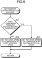
- FIG. 5 is a flowchart illustrating an example of process operations of the control device 4 that relate to the refrigerant circuit protection process.
- the compressor rotation speed is set at two stages according to the level of the condensing pressure for the pressure protection operation not to be excessive.
- the controller 42 determines whether the condensing pressure exceeds the second threshold (step S31). When the condensing pressure is under the second threshold (step S31: No), the controller 42 sets the rotation speed of the compressor 11 at a first rotation speed smaller than a normal rotation speed in order to reduce the condensing pressure (step S32) and ends the process operations illustrated in FIG. 5 .
- step S31 When the condensing pressure exceeds the second threshold (step S31: Yes), the controller 42 sets the rotation speed of the compressor 11 at a second rotation speed smaller than the first rotation speed in order to reduce the condensing pressure (step S33). The controller 42 then ends the process operations illustrated in FIG. 5 .
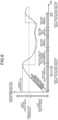
- FIG. 6 is an illustration illustrating an example of transition of heating ability of the heat pump device 1 that relates to the protection control process.
- Ability to heat heated water (referred to as heating ability for convenience) is needed until the current discharged heated-water temperature reaches the target discharged heated-water temperature.
- the target discharged heated-water temperature varies according to the indoor heat load and at least the maximum value of the target discharged heated-water temperature is a value larger than the temperature threshold.
- the first protection control mainly on the water circuit 20 is executed in order to increase the flow of the circulation pump 21 serving as the flow adjustment unit.
- the heat exchange in the heat exchanger 35 of the use-side terminal 31 increases and accordingly the heating ability increases compared to the case where the normal control is executed.
- the heating ability of the use-side terminal 31 is needed and thus, even when the flow of the circulation pump 21 is increased, this does not lead to a decrees in comfortableness to the user that is caused by excessive heating.
- the heating ability is unnecessary and the current discharged heated-water temperature lowers gradually.
- the condensing pressure exceeds the first threshold in the process where the discharged heated-water temperature lowers to the target discharged heated-water temperature, even if the first protection control mainly on the refrigerant circuit 10 that lowers the rotation speed of the compressor 11 is performed, the heating ability is not needed initially and thus comfortableness to the user is not diminished.
- the heat pump device 1 of the embodiment reduces the condensing pressure by increasing the flow of the circulation pump 21 in the water circuit 20. Furthermore, when the discharged heated-water temperature is under the temperature threshold, the heat pump device 1 reduces the condensing pressure by setting the rotation speed of the compressor 11 in the refrigerant circuit 10 at the first rotation speed.
- a switch to protection control mainly on the water circuit 20 is made in the case where the discharged heated-water temperature is at or above the temperature threshold and a switch to protection control mainly on the refrigerant circuit 10 is made in the case where the discharged heated-water temperature is under the temperature threshold.
- the heat pump device 1 When the condensing pressure exceeds the first pressure threshold and exceeds the second pressure threshold, the heat pump device 1 reduces the condensing pressure by setting the rotation speed of the compressor 11 at the second rotation speed. Furthermore, when the condensing pressure exceeds the second pressure threshold and exceeds the third pressure threshold, the heat pump device 1 stops the compressor 11. As a result, it is possible to perform the pressure protection operation appropriately by changing the subject of control in stages according to the level of the condensing pressure.
- the discharged heated-water temperature sensor 26 that is arranged at the outlet of the water heat exchanger 12 and that detects the discharged heated-water temperature that is the temperature of the heated water flowing into the use-side terminal 31 is exemplified as the second detector.
- the second detector however is not limited to the outlet of the water heat exchanger 12, and the second detector only need to detect the discharged heated-water temperature that is the temperature of the heated water until the flow from the outlet of the water heat converter 12 into the inlet of the heat exchanger 35 in the use-side terminal 31 and changes can be made as appropriate.
- the flow adjustment unit is the circulation pump 21 that is provided in the water circuit 20 and the flow of the circulation pump 21 is increased when the discharged heated-water temperature is at above the temperature threshold is exemplified.
- the flow adjustment unit however is not limited to the circulation pump 21 and the flow adjustment unit may be a flow adjustment valve and, in this case, when the discharged heated-water temperature is at or above the temperature threshold, the controller 42 increases the flow of the heated water by opening the flow adjustment valve. As a result, it is possible to reduce the condensing pressure.
- the controller 42 increases the flow of the circulation pump 21 has been exemplified.
- the controller 42 may increase the flow of the circulation pump 21 and increase the flow of heated water by opening the flow adjustment valve, and changes can be made as appropriate.
- each component of each unit illustrated in the drawings need not necessarily be configured physically as illustrated in the drawings.
- specific modes of distribution and integration of each units are not limited to those illustrated in the drawings and all or part of the units can be configured by functional or physical distribution or integration in any unit according to various types of load and usage.
- each device may be executed on a CPU (Central Processing Unit) (or a microcomputer, such as a MPU (Micro Processing Unit) or a MCU (Micro Controller Unit)).
- a CPU Central Processing Unit
- MPU Micro Processing Unit
- MCU Micro Controller Unit
- all or any part of the various types of processing functions may be executed on a program that is analyzed and executed by the CPU (or a microcomputer, such as a MPU or a MCU) or on hardware according to a wired logic.
Landscapes
- Engineering & Computer Science (AREA)
- Physics & Mathematics (AREA)
- Thermal Sciences (AREA)
- Mechanical Engineering (AREA)
- General Engineering & Computer Science (AREA)
- Chemical & Material Sciences (AREA)
- Combustion & Propulsion (AREA)
- Air Conditioning Control Device (AREA)
- Heat-Pump Type And Storage Water Heaters (AREA)
Abstract
Description
- The present invention relates to a heat pump device.
- For example, a heat pump device that includes a refrigerant circuit in which a refrigerant circulates with a compressor and a water circuit in which water circulates and that produces heated water by heat exchange with the refrigerant and that supplies the heated water to a plurality of indoor units using a circulation pump that is provided in the water circuit is known. The heat pump device produces heated water by heat exchange with the refrigerant and circulates the heated water to the indoor units using the circulation pump, thereby adjusting the temperature and humidity of an indoor space in which the indoor units are set.
- In the heat pump device, the pressure of the refrigerant circuit sometimes increases or decreases excessively because of variation in the outdoor temperature, etc. Thus, in order to deal with an excessive increase and decrease of the pressure of the refrigerant circuit, the heat pump device adjusts a flow adjustment valve that adjusts a rotation rate of a compressor in the refrigerant circuit and a flow of the refrigerant in the refrigerant circuit using the detected pressure and temperature of the refrigerant circuit and performs a pressure protection operation on the refrigerant circuit. Citation List
- Patent Literature 1:
Japanese Laid-open Patent Publication No. 2015-205061 - In the conventional heat pump device, however, when the pressure protection operation is performed by only control on the side of the refrigerant circuit, for example, control on the compressor, this sometimes results in an excessive protection operation. When the rotation rate of the compressor is lowered, the flow of the refrigerant and the differential pressure in the refrigerant circuit decrease, condensing and evaporating ability lowers, ability needed to adjust the temperature of the indoor unit is not sufficiently fulfilled, and it takes time to reach an appropriate room temperature, which diminishes comfortableness to a user. Such a problem is not limited to an indoor unit of an air conditioner and it can occur in a water heater that uses heated water that circulates.
- In view of such a problem, an object of the present invention is to provide a heat pump device that makes it possible to minimize a decrease in comfortableness and perform the pressure protection operation as appropriate.
- According to an aspect of an embodiment, the heat pump device including a refrigerant circuit, a water circuit, and a terminal. The refrigerant circuit in which a refrigerant circulates includes a compressor. The water circuit in which water circulates, includes a flow adjustor that adjusts a flow of the water. The water circuit produces heated water by heat exchange of the water with the refrigerant. The terminal is connected to the water circuit. The heat pump device includes a first detector, a second detector and a controller. The first detector detects a condensing pressure of the refrigerant of the refrigerant circuit. The second detector detects a discharged heated-water temperature that is a temperature of the water flowing into the terminal. The controller executes a protection operation of adjusting the condensing pressure of the refrigerant when the condensing pressure that is detected by the first detector exceeds a pressure threshold. The controller selects, as a subject of control in the protection operation, any one of the compressor and the flow adjustor based on the discharged heated-water temperature that is detected by the second detector. Advantageous Effects of Invention
- It is possible to minimize a decrease in comfortableness and perform a pressure protection operation as appropriate as an aspect.
-
-
FIG. 1 is an illustration illustrating an example of a heat pump device of an embodiment. -
FIG. 2 is an illustration illustrating an example of an operation of protecting a refrigerant circuit with respect to each condensing pressure. -
FIG. 3 is an illustration illustrating an example of a subject of control with respect to each discharged heated-water temperature. -
FIG. 4 is a flowchart illustrating an example of process operations of a control device that relate to a protection control process. -
FIG. 5 is a flowchart illustrating an example of process operations of the control device that relate to a refrigerant circuit protection process. -
FIG. 6 is an illustration illustrating an example of transition of heating ability of the heat pump device that relates to the protection control process. - An embodiment of a heat pump device, etc., disclosed in the preset application will be described in detail below according to the drawings. Note that the embodiment does not limit the disclosed technique. Each embodiment illustrated below may be modified as appropriate within a range where no inconsistency is caused.
-
FIG. 1 is an illustration illustrating an example of aheat pump device 1 of the present embodiment. Theheat pump device 1 illustrated inFIG. 1 includes heat source equipment 2, a use-side terminal group 3, and a control device 4. The heat source equipment 2 includes arefrigerant circuit 10 and awater circuit 20. Therefrigerant circuit 10 is a line in which a refrigerant circulates inside and external air and the refrigerant perform heat exchange. Thewater circuit 20 is a line in which water circulates and the refrigerant from therefrigerant circuit 10 and water perform heat exchange. The use-side terminal group 3 is set in an indoor space and is, for example, a plurality of use-side terminals 31, such as a floor-heating device of a direct contact system that is used in an environment where a user is able to make direct contact, a fan convector of a forced convection system, and a panel heater of a natural convection system. The control device 4 controls the entireheat pump device 1. - The
refrigerant circuit 10 includes acompressor 11, awater heat exchanger 12, apressure reducing valve 13, and anoutdoor heat exchanger 17, which are connected mutually via each set of refrigerant piping. - The
compressor 11 is an ability variable compressor of a high pressure vessel type whose operation capacity is variable according to driving of a motor that is not illustrated in the drawings and whose rotation speed is controlled by an inverter. Thewater heat exchanger 12 is a heat exchanger that causes heat exchange between the refrigerant and water passing inside. The water heat exchanger 12 functions as a condenser that condenses the refrigerant passing inside in a heated water heating operation. Thewater heat exchanger 12 is connected to thecompressor 11 via arefrigerant pipe 16A on a refrigerant inlet side. Thewater heat exchanger 12 is connected to thepressure reducing valve 13 via arefrigerant pipe 16B on a refrigerant outlet side. - The
pressure reducing valve 13 is provided in therefrigerant pipe 16B and is an electronic expansion valve that is driven by a pulse motor not illustrated in the drawings. The opening of thepressure reducing valve 13 is adjusted according to the number of pulses applied to the pulse motor and thus the volume of the refrigerant flowing into theoutdoor heat exchanger 17 is adjusted. Thepressure reducing valve 13 is connected to thewater heat exchanger 12 via therefrigerant pipe 16B on a refrigerant inlet side. Thewater heat exchanger 12 is connected to thecompressor 11 via therefrigerant pipe 16B on the refrigerant outlet side. The refrigerant flowing into theoutdoor heat exchanger 17 causes heat exchange between the refrigerant passing inside and outdoor air. Theoutdoor heat exchanger 17 functions as an evaporator that evaporates the refrigerant passing inside in the heated water heating operation. Theoutdoor heat exchanger 17 is connected to thepressure reducing valve 13 via therefrigerant pipe 16B on the refrigerant inlet side. Theoutdoor heat exchanger 17 is connected to thecompressor 11 via therefrigerant pipe 16B on the refrigerant outlet side. - Furthermore, the
refrigerant circuit 10 includes ahigh pressure sensor 14 and alow pressure sensor 15. Thehigh pressure sensor 14 is provided between thecompressor 11 and thewater heat exchanger 12 and detects a condensing pressure of the refrigerant on an ejection side of thecompressor 11. Thehigh pressure sensor 14 is a first detector that detects a condensing pressure of the refrigerant on an ejection side of thecompressor 11 that circulates the refrigerant in therefrigerant circuit 10. Thelow pressure sensor 15 is provided between theoutdoor heat exchanger 17 and thecompressor 11 and detects a pressure of the refrigerant on a suction side of thecompressor 11. - The
water circuit 20 produces heated water by performing heat exchange between the refrigerant that circulates in therefrigerant circuit 10 and water that circulates in thewater circuit 20. Thewater circuit 20 includes thewater heat exchanger 12, acirculation pump 21, abuffer tank 22, and abypass pipe 23 that are mutually connected via each set ofliquid piping 24. Thewater circuit 20 includes a flow-outpipe 24A via which heated water flows from thewater heat exchanger 12 into the use-side terminal group 3 and a flow-inpipe 24B via which heated water flows from the use-side terminal group 3 into thewater heat exchanger 12. - The
circulation pump 21 is driven, thereby circulating water in thewater circuit 20. Note that thecirculation pump 21 is a flow adjustment unit that adjusts the flow of water and whose operation capacity is variable according to driving of a motor that is not illustrated in the drawings and whose rotation speed is controlled by an inverter. Thebuffer tank 22 is a tank that stores water that is circulated in thewater circuit 20. Thebypass pipe 23 is piping for directly connecting the flow-outpipe 24A and the flow-inpipe 24B when the flow of heated water from thewater circuit 20 into the use-side terminal group 3 is blocked. - The
water circuit 20 includes a discharged heated-water temperature sensor 26 and areturn temperature sensor 25. The discharged heated-water temperature sensor 26 is arranged at the outlet of thewater heat exchanger 12 and is a second detector that detects a discharged heated-water temperature that is a temperature of the heated water flowing into the use-side terminal 31. Thereturn temperature sensor 25 is arranged at the inlet of thewater heat exchanger 12 and detects a temperature of the heated water flowing into thewater heat exchanger 12. - The use-side terminal group 3 includes the use-
side terminals 31, abranch pipe 32 and a mergingpipe 33. Thebranch pipe 32 is piping that branches the heated water from thewater circuit 20 to each use-side terminal 31. The mergingpipe 33 is piping that merges the heated water having passed through each use-side terminal 31 and returns the merged heated water to thewater circuit 20. - The use-
side terminal 31 includes aheat exchanger 35, a flow adjustment valve 34, and an outletwater temperature sensor 36. Theheat exchanger 35 performs heat exchange between the heated water from thewater circuit 20 branching from thebranch pipe 32 and, for example, the air in the indoor space. The flow adjustment valve 34 is a valve that adjusts the flow of the heated water flowing from thebranch pipe 32 into theheat exchanger 35. The outletwater temperature sensor 36 is a sensor that detects a temperature of the heated water flowing from theheat exchanger 35. - Each use-
side terminal 31 includes, for example, a terminal of the direct contact system, a terminal of the forced convection system, a terminal of the natural convection system, or the like. The terminal of the direct contact system is, for example, a floor-heating device that makes direct contact with a user and that adjusts the room temperature by radiating heat into the indoor space using radiation heat obtained in a way that the heated water of thewater circuit 20 flows into a radiation panel (the heat exchanger 35). The terminal of the forced convection system is, for example, a fan convector that adjusts the temperature of the indoor space by causing the air that is heated by theheat exchanger 35 by heat exchange with the heated water flowing in from thewater circuit 20 to blow by forced convection of a blower fan, or the like. Like the terminal of the direct contact system, the terminal of the natural convection system adjusts the temperature of the indoor space by radiation heat obtained by causing the heated water of thewater circuit 20 to flow into a radiation panel (the heat exchanger 35). The terminal of the natural convection system is, for example, a panel heater. - The control device 4 includes a
storage unit 41 that stores various types of information and acontroller 42 that controls the entireheat pump device 1. Thestorage unit 41 stores pressure thresholds that are thresholds of the condensing pressure, for example, a first threshold, a second threshold, and a third threshold. Each of the thresholds has the relation: the first threshold<the second threshold<the third threshold. The first threshold is a threshold for distinguishing a condensing pressure higher than a condensing pressure in a normal stable operating state (a condensing pressure that makes it possible to ensure reliability of a freezing cycle). The second threshold is a threshold for distinguishing a condensing pressure that is too large to be kept at or under the first threshold by first protection control to be described below. The third threshold is a threshold for distinguishing a condensing pressure that is large such that it is necessary to stop thecompressor 11 immediately in view of reliability. Thus, the threshold can be also referred to as a threshold that determines a protection operation to which a switch is made according to a high condensing pressure. - The
storage unit 41 stores a temperature threshold that is a fixed threshold for selecting a subject of control from the discharged heated-water temperature. - The
controller 42 includes arefrigerant circuit controller 42A that controls therefrigerant circuit 10 and awater circuit controller 42B that controls thewater circuit 20. When the condensing pressure that is detected by the high-pressure sensor 14 exceeds the first threshold, thecontroller 42 executes the protection operation of adjusting the condensing pressure of the refrigerant. Based on the discharged heated-water temperature that is detected by the discharged heated-water temperature sensor 26, thecontroller 42 selects any one of thecompressor 11 and the flow adjustment unit as a subject of control in the protection operation. Specifically, when the detected discharged heated-water temperature is at or above the temperature threshold that is stored in thestorage unit 41, thecontroller 42 sets, for the subject of control, the flow of thecirculation pump 21 that is the flow adjustment unit and, when the discharged heated-water is under the temperature threshold, the rotation speed of thecompressor 11 is set for the subject of control. - The
refrigerant circuit controller 42A in thecontroller 42 includes a temperature controller 42A1 that changes the rotation speed of thecompressor 11 such that the discharged heated-water temperature reaches a target discharged heated-water temperature. Note that the target discharged heated-water temperature is set based on a difference between a setting temperature that is set by the user and a room temperature (indoor heat load). The setting temperature is a temperature that is input as a room temperature that the user of each use-side terminal 31 requests and the room temperature is detected by a room temperature sensor that is not illustrated in the drawings and that is provided in the use-side terminal 31. A difference between a setting temperature and a room temperature is calculated per use-site terminal 31 and a target discharged heated-water temperature that is determined previously by a test, or the like, based on the maximum value of the difference is set. The temperature controller 42A1 controls the rotation speed of thecompressor 11 according to an indoor heat load. For example, the larger the rotation speed of thecompressor 11 increases, the more the condensing temperature of the refrigerant that circulates in therefrigerant circuit 10 increases, which increases an in increase in the discharged heated-water temperature of the water on which the heat exchange is performed because the condensing temperature of the refrigerant increases. - When the discharged heated-water temperature is at or above the temperature threshold, the
water circuit controller 42B in thecontroller 42 performs control such that the flow of thecirculation pump 21 serving as the flow adjustment unit increases. Accordingly, the heat exchange between the refrigerant and water in thewater heat exchanger 12 increases and thus the condensing pressure decreases. Specifically, when the discharged heated-water temperature is smaller than the target discharged heated-water temperature and is at or above the temperature threshold, thewater circuit controller 42B increases the flow of thecirculation pump 21. The condition that "the discharged heated-water temperature is smaller than the target discharged heated-water temperature" will be described below. - When the discharged heated-water temperature corresponds to at least one of the condition of being equal to or larger than the target heated-water temperature and the condition of being under the temperature threshold, the
refrigerant circuit controller 42A in thecontroller 42 reduces the rotation speed of thecompressor 11 and reduces the condensing pressure. -
FIG. 2 is an illustration illustrating an example of an operation of protecting therefrigerant circuit 10 with respect to each condensing pressure. When a condensing pressure is at or under the first threshold, thecontroller 42 does not execute the protection operation and keeps a normal heated-water heating operation. When the condensing pressure exceeds the first threshold and is at or under the second threshold, thecontroller 42 determines that the condensing pressure is a condensing pressure higher than normal and executes the first protection control. The first protection control is control of selecting any one of the flow adjustment unit (the circulation pump 21) and the compressor as a subject of control in the protection operation based on the discharged heated-water temperature and reducing the condensing pressure. - When executing the first protection control, in the case where the discharged heated-water temperature that is detected is at or above the temperature threshold that is stored in the
storage unit 41, thecontroller 42 sets the flow of thecirculation pump 21 serving as the flow adjustment unit for the subject of control and, in the case where the discharged heated-water temperature is under the temperature threshold, thecontroller 42 sets the rotation speed of thecompressor 11 for the subject of control. As described above, the reason for switching the protection control according to the magnitude of the discharged heated-temperature with respect to the temperature threshold is that the effect of reducing the refrigerant pressure by increasing the flow of water differs depending on the discharged heated-water temperature. The indoor heat load is large when the discharged heated-water temperature is high and thus the heat discharge of water in each use-side terminal 31 is large. When the heat discharge of water in each use-side terminal 31 is large, the difference between the discharged heated-water temperature and a return temperature increases. When the difference between the discharged heated-water temperature and the return temperature is large, a difference in temperature between the water and the refrigerant increases in thewater heat exchanger 12. Thus, increasing the flow of the water increases the effect of reducing the refrigerant pressure. On the other hand, when the discharged heated-water temperature is low, because the difference in temperature between the water and the refrigerant is small in thewater heat exchanger 12, the effect of reducing the condensing pressure is low even when the flow of the water is increased. Thus, the flow of thecirculation pump 21 is not set for the subject of control. - When the condensing pressure exceeds the second threshold and is at or under the third threshold, the
controller 42 executes second protection control. The second protection control is control of selecting thecompressor 11 in therefrigerant circuit 10 as the subject of control in the protection operation and reducing the condensing pressure by lowering the rotation speed of thecompressor 11. The second threshold is a threshold for distinguishing a condensing pressure that is too large to be kept at or under the first threshold by the first protection control to be described below. For this reason, in order to reduce the condensing pressure, it is necessary to lower the rotation speed of thecompressor 11 even if the discharged heated-water temperature lowers. - When the condensing pressure exceeds the third threshold, the
controller 42 executes third protection control. The third protection control is control of stopping thecompressor 11 in therefrigerant circuit 10. The third threshold is a threshold for distinguishing a condensing pressure that is large such that it is necessary to stop thecompressor 11 immediately in view of reliability. Stopping thecompressor 11 makes it possible to inhibit reliability in reducing the condensing pressure from lowering. -
FIG. 3 is an illustration illustrating an example of a subject of control with respect to each discharged heated-water temperature. When the discharged heated-water temperature is under the temperature threshold under the first protection control, thecontroller 42 selects thecompressor 11 in therefrigerant circuit 10 and controls the rotation speed of thecompressor 11 to reduce the condensing pressure. When the discharged heated-water temperature is at or above the temperature threshold under the first protection control, thecontroller 42 performs control to increase the flow of thecirculation pump 21 in therefrigerant circuit 10. - As described above, when the condensing pressure exceeds the first pressure threshold, the
controller 42 executes the first protection control of selecting any one of the flow adjustment unit and thecompressor 11 as the subject of control in the protection operation based on the discharged heated-water temperature that is detected and reducing the condensing pressure. - When the condensing pressure exceeds the second pressure threshold higher than the first pressure threshold, the
refrigerant circuit controller 42A in thecontroller 42 executes the second protection control of selecting thecompressor 11 in therefrigerant circuit 10 as the subject of control in the protection operation and reducing the condensing pressure. When the condensing pressure exceeds the third pressure threshold higher than the second pressure threshold, therefrigerant circuit controller 42A in thecontroller 42 executes the third protection control of stopping thecompressor 11. -
FIG. 4 is a flowchart illustrating an example of process operations of the control device 4 that relate to a protection control process. According toFIG. 4 , thecontroller 42 in the control device 4 determines whether the condensing pressure exceeds the first threshold (step S11). When the condensing pressure exceeds the first threshold (step S11: Yes), thecontroller 42 determines whether the condensing pressure exceeds the second threshold (step S12). - When the condensing pressure does not exceed the second threshold (step S12: No), the
controller 42 determines whether the discharged heated-water temperature is smaller than the target discharged heated-water temperature and is at or above the temperature threshold (step S13). When the discharged heated-water temperature is smaller than the target discharged heated-water temperature and is at or above the temperature threshold (step S13: Yes), thecontroller 42 controls thecirculation pump 21 in order to increase the flow of thecirculation pump 21 in the first protection control (step S14) and determines whether a given time elapses (step S15). Note that the process at step S15 is a process of determining whether the given time elapses from the start of the process at step S14 or step S17. - When the given time elapses (step S15: Yes), the
controller 42 returns to the process at step S11 in order to determine whether the condensing pressure exceeds the first threshold. When the condensing pressure does not exceed the first threshold (step S11: No), thecontroller 42 does not perform the protection control and returns to the process at step S11 in order to determine whether the condensing pressure exceeds the first threshold. - When the condensing pressure exceeds the second threshold (step S12: Yes), the
controller 42 determines whether the condensing pressure exceeds the third threshold (step S16). When the condensing pressure does not exceed the third threshold (step S16: No), thecontroller 42 executes a refrigerant circuit protection process illustrated inFIG. 5 (step S17). Thecontroller 42 then returns to the process at step S15 in order to determine whether the given time elapses. - When the condensing pressure exceeds the third threshold (step S16: Yes), the
controller 42 stops the compressor 11 (step S18) and ends the process operations illustrated inFIG. 4 . When the discharged heated-water temperature corresponds to at least any one of the condition of being equal to or larger than the target discharged heated-water temperature or the condition of being under the temperature threshold (step S13: No), thecontroller 42 shifts to the process at step S17 in order to execute the refrigerant circuit protection process illustrated inFIG. 5 . When the given time does not elapse (step S15: No), thecontroller 42 returns to the process at step S15 in order to determine whether the given time elapses. -
FIG. 5 is a flowchart illustrating an example of process operations of the control device 4 that relate to the refrigerant circuit protection process. In the refrigerant circuit protection process, the compressor rotation speed is set at two stages according to the level of the condensing pressure for the pressure protection operation not to be excessive. According toFIG. 5 , thecontroller 42 determines whether the condensing pressure exceeds the second threshold (step S31). When the condensing pressure is under the second threshold (step S31: No), thecontroller 42 sets the rotation speed of thecompressor 11 at a first rotation speed smaller than a normal rotation speed in order to reduce the condensing pressure (step S32) and ends the process operations illustrated inFIG. 5 . - When the condensing pressure exceeds the second threshold (step S31: Yes), the
controller 42 sets the rotation speed of thecompressor 11 at a second rotation speed smaller than the first rotation speed in order to reduce the condensing pressure (step S33). Thecontroller 42 then ends the process operations illustrated inFIG. 5 . -
FIG. 6 is an illustration illustrating an example of transition of heating ability of theheat pump device 1 that relates to the protection control process. Ability to heat heated water (referred to as heating ability for convenience) is needed until the current discharged heated-water temperature reaches the target discharged heated-water temperature. Note that the target discharged heated-water temperature varies according to the indoor heat load and at least the maximum value of the target discharged heated-water temperature is a value larger than the temperature threshold. When the discharged heated-water temperature is at or above the temperature threshold in the process of increasing toward the target discharged heated-water temperature and the condensing pressure exceeds the first threshold, the first protection control mainly on thewater circuit 20 is executed in order to increase the flow of thecirculation pump 21 serving as the flow adjustment unit. When the flow of thecirculation pump 21 increases, the heat exchange in theheat exchanger 35 of the use-side terminal 31 increases and accordingly the heating ability increases compared to the case where the normal control is executed. When the current discharged heated-water temperature is smaller than the target discharged heated-water temperature and the current discharged heated-water temperature is at or above the temperature threshold, however, the heating ability of the use-side terminal 31 is needed and thus, even when the flow of thecirculation pump 21 is increased, this does not lead to a decrees in comfortableness to the user that is caused by excessive heating. - On the other hand, when the current discharged heated-water temperature is above the target discharged heated-water temperature, the heating ability is unnecessary and the current discharged heated-water temperature lowers gradually. When the condensing pressure exceeds the first threshold in the process where the discharged heated-water temperature lowers to the target discharged heated-water temperature, even if the first protection control mainly on the
refrigerant circuit 10 that lowers the rotation speed of thecompressor 11 is performed, the heating ability is not needed initially and thus comfortableness to the user is not diminished. - When the detected condensing pressure exceeds the first pressure threshold and the discharged heated-water temperature is at or above the temperature threshold, the
heat pump device 1 of the embodiment reduces the condensing pressure by increasing the flow of thecirculation pump 21 in thewater circuit 20. Furthermore, when the discharged heated-water temperature is under the temperature threshold, theheat pump device 1 reduces the condensing pressure by setting the rotation speed of thecompressor 11 in therefrigerant circuit 10 at the first rotation speed. In other words, even when the condensing pressure increases, a switch to protection control mainly on thewater circuit 20 is made in the case where the discharged heated-water temperature is at or above the temperature threshold and a switch to protection control mainly on therefrigerant circuit 10 is made in the case where the discharged heated-water temperature is under the temperature threshold. As a result, it is possible to perform the pressure protection operation appropriately while minimizing a decrease in comfortableness. - When the condensing pressure exceeds the first pressure threshold and exceeds the second pressure threshold, the
heat pump device 1 reduces the condensing pressure by setting the rotation speed of thecompressor 11 at the second rotation speed. Furthermore, when the condensing pressure exceeds the second pressure threshold and exceeds the third pressure threshold, theheat pump device 1 stops thecompressor 11. As a result, it is possible to perform the pressure protection operation appropriately by changing the subject of control in stages according to the level of the condensing pressure. - Note that, for convenience of description, the discharged heated-
water temperature sensor 26 that is arranged at the outlet of thewater heat exchanger 12 and that detects the discharged heated-water temperature that is the temperature of the heated water flowing into the use-side terminal 31 is exemplified as the second detector. The second detector however is not limited to the outlet of thewater heat exchanger 12, and the second detector only need to detect the discharged heated-water temperature that is the temperature of the heated water until the flow from the outlet of thewater heat converter 12 into the inlet of theheat exchanger 35 in the use-side terminal 31 and changes can be made as appropriate. - The case where the flow adjustment unit is the
circulation pump 21 that is provided in thewater circuit 20 and the flow of thecirculation pump 21 is increased when the discharged heated-water temperature is at above the temperature threshold is exemplified. The flow adjustment unit however is not limited to thecirculation pump 21 and the flow adjustment unit may be a flow adjustment valve and, in this case, when the discharged heated-water temperature is at or above the temperature threshold, thecontroller 42 increases the flow of the heated water by opening the flow adjustment valve. As a result, it is possible to reduce the condensing pressure. - The case where, when the discharged heated-water temperature is at or above the temperature threshold, the
controller 42 increases the flow of thecirculation pump 21 has been exemplified. When the discharged heated-water temperature is at or above the temperature threshold, however, thecontroller 42 may increase the flow of thecirculation pump 21 and increase the flow of heated water by opening the flow adjustment valve, and changes can be made as appropriate. - Each component of each unit illustrated in the drawings need not necessarily be configured physically as illustrated in the drawings. In other words, specific modes of distribution and integration of each units are not limited to those illustrated in the drawings and all or part of the units can be configured by functional or physical distribution or integration in any unit according to various types of load and usage.
- Furthermore, all or given part of various types of processing functions implemented by each device may be executed on a CPU (Central Processing Unit) (or a microcomputer, such as a MPU (Micro Processing Unit) or a MCU (Micro Controller Unit)). Needless to say, all or any part of the various types of processing functions may be executed on a program that is analyzed and executed by the CPU (or a microcomputer, such as a MPU or a MCU) or on hardware according to a wired logic.
-
- 1
- HEAT PUMP DEVICE
- 3
- USE-SIDE TERMINAL GROUP
- 4
- CONTROL DEVICE
- 10
- REFRIGERANT CIRCUIT
- 11
- COMPRESSOR
- 14
- HIGH PRESSURE SENSOR
- 20
- WATER CIRCUIT
- 21
- CIRCULATION PUMP
- 26
- DISCHARGED HEATED-WATER TEMPERATURE SENSOR
- 42
- CONTROLLER
- 42A
- REFRIGERANT CIRCUIT CONTROLLER
- 42B
- WATER CIRCUIT CONTROLLER
- 42A1
- TEMPERATURE CONTROLLER
Claims (7)
- A heat pump device comprising:a refrigerant circuit that includes a compressor and in which a refrigerant circulates;a water circuit in which water circulates, that includes a flow adjustor that adjusts a flow of the water, and that produces heated water by heat exchange of the water with the refrigerant; anda terminal that is connected to the water circuit,wherein the heat pump device includes:a first detector that detects a condensing pressure of the refrigerant of the refrigerant circuit;a second detector that detects a discharged heated-water temperature that is a temperature of the water flowing into the terminal; anda controller that executes a protection operation of adjusting the condensing pressure of the refrigerant when the condensing pressure that is detected by the first detector exceeds a pressure threshold, andthe controller selects, as a subject of control in the protection operation, any one of the compressor and the flow adjustor based on the discharged heated-water temperature that is detected by the second detector.
- The heat pump device according to claim 1,
wherein the controller sets the flow adjustor for the subject of control when the discharged heated-water temperature is at or above a temperature threshold and sets the compressor for the subject of control when the discharged heated-temperature is under the temperature threshold. - The heat pump device according to claim 1,
wherein the controller includes a temperature controller that changes a rotation speed of the compressor such that the discharged heated-water temperature reaches a target discharged heated-water temperature, and
when the discharged heated-water temperature is smaller than the target discharged heated-water temperature and is at or above the temperature threshold, the controller reduces the condensing pressure by controlling the flow adjustor and, when the discharged heated-water temperature corresponds to at least one of a condition of being equal to or larger than the target discharged heated-water temperature and a condition of being under the temperature threshold, the controller reduces the condensing pressure by reducing the rotation speed of the compressor. - The heat pump device according to claim 2 or 3, wherein the flow adjustor is a circulation pump that is provided in the water circuit, and
when the discharged heated-water temperature is at or above the temperature threshold, the controller increases a flow of the circulation pump. - The heat pump device according to claim 2 or 3, wherein the flow adjustor is a flow adjustment valve that is provided in the water circuit, and
when the discharged heated-water temperature is at or above the temperature threshold, the controller increases the flow of the heated water by opening the flow adjustment valve. - The heat pump device according to claim 1, whereinwhen the condensing pressure exceeds a first pressure threshold, the controller selects any one of the flow adjustor and the compressor as the subject of control in the protection operation based on the discharged heated-water temperature that is detected by the second detector and reduces the condensing pressure,when the condensing pressure exceeds the first pressure threshold and exceeds a second pressure threshold higher than the first pressure threshold, the controller selects the compressor as the subject of control in the protection operation and reduces the condensing pressure, andwhen the condensing pressure exceeds the second pressure threshold and exceeds a third pressure threshold higher than the second pressure threshold, the controller stops the compressor.
- The heat pump device according to any one of claims 1 to 3, wherein the first detector is a high-pressure sensor that detects the condensing pressure on an ejection side of the compressor that circulates the refrigerant in the refrigerant circuit.
Applications Claiming Priority (2)
| Application Number | Priority Date | Filing Date | Title |
|---|---|---|---|
| JP2022052475A JP7310964B1 (en) | 2022-03-28 | 2022-03-28 | heat pump equipment |
| PCT/JP2023/011974 WO2023190228A1 (en) | 2022-03-28 | 2023-03-24 | Heat pump device |
Publications (2)
| Publication Number | Publication Date |
|---|---|
| EP4502497A1 true EP4502497A1 (en) | 2025-02-05 |
| EP4502497A4 EP4502497A4 (en) | 2026-04-15 |
Family
ID=87201242
Family Applications (1)
| Application Number | Title | Priority Date | Filing Date |
|---|---|---|---|
| EP23780238.4A Pending EP4502497A4 (en) | 2022-03-28 | 2023-03-24 | HEAT PUMP DEVICE |
Country Status (6)
| Country | Link |
|---|---|
| US (1) | US20250198678A1 (en) |
| EP (1) | EP4502497A4 (en) |
| JP (1) | JP7310964B1 (en) |
| CN (1) | CN118871727A (en) |
| AU (1) | AU2023243001B2 (en) |
| WO (1) | WO2023190228A1 (en) |
Family Cites Families (8)
| Publication number | Priority date | Publication date | Assignee | Title |
|---|---|---|---|---|
| JP3912035B2 (en) * | 2001-05-18 | 2007-05-09 | 松下電器産業株式会社 | Heat pump water heater |
| JP4412208B2 (en) * | 2005-03-17 | 2010-02-10 | パナソニック株式会社 | Heat pump type water heater |
| JP2011027372A (en) * | 2009-07-29 | 2011-02-10 | Hitachi Appliances Inc | Refrigerating cycle device and heat pump water heater |
| JP2013170764A (en) * | 2012-02-21 | 2013-09-02 | Fujitsu General Ltd | Heat pump cycle device |
| WO2014181401A1 (en) * | 2013-05-08 | 2014-11-13 | 三菱電機株式会社 | Circulation and heating apparatus |
| JP6304996B2 (en) * | 2013-10-03 | 2018-04-04 | 三菱電機株式会社 | Water heater |
| JP6389635B2 (en) | 2014-04-21 | 2018-09-12 | 株式会社三共 | Slot machine |
| JP6488160B2 (en) * | 2015-03-10 | 2019-03-20 | リンナイ株式会社 | Heat pump heating device |
-
2022
- 2022-03-28 JP JP2022052475A patent/JP7310964B1/en active Active
-
2023
- 2023-03-24 WO PCT/JP2023/011974 patent/WO2023190228A1/en not_active Ceased
- 2023-03-24 US US18/847,687 patent/US20250198678A1/en active Pending
- 2023-03-24 CN CN202380026581.3A patent/CN118871727A/en active Pending
- 2023-03-24 EP EP23780238.4A patent/EP4502497A4/en active Pending
- 2023-03-24 AU AU2023243001A patent/AU2023243001B2/en active Active
Also Published As
| Publication number | Publication date |
|---|---|
| EP4502497A4 (en) | 2026-04-15 |
| AU2023243001A1 (en) | 2024-10-03 |
| WO2023190228A1 (en) | 2023-10-05 |
| US20250198678A1 (en) | 2025-06-19 |
| JP7310964B1 (en) | 2023-07-19 |
| AU2023243001B2 (en) | 2026-01-22 |
| CN118871727A (en) | 2024-10-29 |
| JP2023145154A (en) | 2023-10-11 |
Similar Documents
| Publication | Publication Date | Title |
|---|---|---|
| CN107003038B (en) | Apparatus and method for mixing water heating and air cooling and their control | |
| US9644876B2 (en) | Refrigeration cycle apparatus | |
| US9557085B2 (en) | Heat pump apparatus | |
| US10816224B2 (en) | Heat-pump air-conditioning hot-water supply device | |
| EP2466220A1 (en) | Air conditioning system and method of controlling air conditioning system | |
| US11802724B2 (en) | Air-conditioning apparatus with simultaneous heating and defrosting modes | |
| EP2716989A1 (en) | Temperature adjusting system, air conditioning system, and control method | |
| US5046323A (en) | Multi-system air conditioner | |
| EP4116638B1 (en) | Air conditioner and air discharge method of air conditioner | |
| US12092383B2 (en) | Refrigeration cycle device | |
| CN101270905B (en) | Simultaneous heating and cooling multi-air conditioner and control method thereof | |
| US11525599B2 (en) | Controller of air conditioning apparatus, outdoor unit, relay unit, heat source unit, and air conditioning apparatus | |
| CN113405155A (en) | Expansion valve control method and device and multi-connected air conditioner | |
| AU2023243001B2 (en) | Heat pump device | |
| JP7571523B2 (en) | Heat pump cycle equipment | |
| EP3650770A1 (en) | Refrigeration cycle device | |
| KR20110117974A (en) | Heat pump type hot water supply device | |
| CN120702077A (en) | Method and device for noise reduction of multi-split air conditioning system, multi-split air conditioning system, and computer-readable storage medium | |
| EP4521038B1 (en) | Heating medium circulation apparatus | |
| EP3764022B1 (en) | Hot water supply device | |
| KR20080065196A (en) | How to control overload operation of the air conditioner | |
| EP3348938B1 (en) | Refrigeration cycle system | |
| CN110953739A (en) | Control method of refrigeration system, refrigeration system and refrigerator | |
| JP7829723B2 (en) | Air conditioning equipment and air conditioning systems | |
| EP4502507A1 (en) | Heat pump device |
Legal Events
| Date | Code | Title | Description |
|---|---|---|---|
| STAA | Information on the status of an ep patent application or granted ep patent |
Free format text: STATUS: THE INTERNATIONAL PUBLICATION HAS BEEN MADE |
|
| PUAI | Public reference made under article 153(3) epc to a published international application that has entered the european phase |
Free format text: ORIGINAL CODE: 0009012 |
|
| STAA | Information on the status of an ep patent application or granted ep patent |
Free format text: STATUS: REQUEST FOR EXAMINATION WAS MADE |
|
| 17P | Request for examination filed |
Effective date: 20240918 |
|
| AK | Designated contracting states |
Kind code of ref document: A1 Designated state(s): AL AT BE BG CH CY CZ DE DK EE ES FI FR GB GR HR HU IE IS IT LI LT LU LV MC ME MK MT NL NO PL PT RO RS SE SI SK SM TR |
|
| DAV | Request for validation of the european patent (deleted) | ||
| DAX | Request for extension of the european patent (deleted) | ||
| A4 | Supplementary search report drawn up and despatched |
Effective date: 20260318 |
|
| RIC1 | Information provided on ipc code assigned before grant |
Ipc: F25B 1/00 20060101AFI20260312BHEP Ipc: F24H 4/02 20220101ALI20260312BHEP Ipc: F24H 15/176 20220101ALI20260312BHEP Ipc: F24H 15/219 20220101ALI20260312BHEP Ipc: F24H 15/242 20220101ALI20260312BHEP Ipc: F24H 15/34 20220101ALI20260312BHEP Ipc: F24H 15/38 20220101ALI20260312BHEP Ipc: F25B 30/02 20060101ALI20260312BHEP Ipc: F25B 49/02 20060101ALI20260312BHEP Ipc: F25B 49/00 20060101ALI20260312BHEP |