EP4502458A1 - Vehicle lamp - Google Patents
Vehicle lamp Download PDFInfo
- Publication number
- EP4502458A1 EP4502458A1 EP23779972.1A EP23779972A EP4502458A1 EP 4502458 A1 EP4502458 A1 EP 4502458A1 EP 23779972 A EP23779972 A EP 23779972A EP 4502458 A1 EP4502458 A1 EP 4502458A1
- Authority
- EP
- European Patent Office
- Prior art keywords
- light
- light emitting
- emitting element
- inner lens
- intermediate member
- Prior art date
- Legal status (The legal status is an assumption and is not a legal conclusion. Google has not performed a legal analysis and makes no representation as to the accuracy of the status listed.)
- Pending
Links
Images




Classifications
-
- F—MECHANICAL ENGINEERING; LIGHTING; HEATING; WEAPONS; BLASTING
- F21—LIGHTING
- F21S—NON-PORTABLE LIGHTING DEVICES; SYSTEMS THEREOF; VEHICLE LIGHTING DEVICES SPECIALLY ADAPTED FOR VEHICLE EXTERIORS
- F21S41/00—Illuminating devices specially adapted for vehicle exteriors, e.g. headlamps
- F21S41/60—Illuminating devices specially adapted for vehicle exteriors, e.g. headlamps characterised by a variable light distribution
- F21S41/65—Illuminating devices specially adapted for vehicle exteriors, e.g. headlamps characterised by a variable light distribution by acting on light sources
- F21S41/663—Illuminating devices specially adapted for vehicle exteriors, e.g. headlamps characterised by a variable light distribution by acting on light sources by switching light sources
-
- F—MECHANICAL ENGINEERING; LIGHTING; HEATING; WEAPONS; BLASTING
- F21—LIGHTING
- F21S—NON-PORTABLE LIGHTING DEVICES; SYSTEMS THEREOF; VEHICLE LIGHTING DEVICES SPECIALLY ADAPTED FOR VEHICLE EXTERIORS
- F21S41/00—Illuminating devices specially adapted for vehicle exteriors, e.g. headlamps
- F21S41/10—Illuminating devices specially adapted for vehicle exteriors, e.g. headlamps characterised by the light source
- F21S41/14—Illuminating devices specially adapted for vehicle exteriors, e.g. headlamps characterised by the light source characterised by the type of light source
- F21S41/141—Light emitting diodes [LED]
- F21S41/143—Light emitting diodes [LED] the main emission direction of the LED being parallel to the optical axis of the illuminating device
-
- F—MECHANICAL ENGINEERING; LIGHTING; HEATING; WEAPONS; BLASTING
- F21—LIGHTING
- F21S—NON-PORTABLE LIGHTING DEVICES; SYSTEMS THEREOF; VEHICLE LIGHTING DEVICES SPECIALLY ADAPTED FOR VEHICLE EXTERIORS
- F21S41/00—Illuminating devices specially adapted for vehicle exteriors, e.g. headlamps
- F21S41/10—Illuminating devices specially adapted for vehicle exteriors, e.g. headlamps characterised by the light source
- F21S41/14—Illuminating devices specially adapted for vehicle exteriors, e.g. headlamps characterised by the light source characterised by the type of light source
- F21S41/141—Light emitting diodes [LED]
- F21S41/151—Light emitting diodes [LED] arranged in one or more lines
-
- F—MECHANICAL ENGINEERING; LIGHTING; HEATING; WEAPONS; BLASTING
- F21—LIGHTING
- F21S—NON-PORTABLE LIGHTING DEVICES; SYSTEMS THEREOF; VEHICLE LIGHTING DEVICES SPECIALLY ADAPTED FOR VEHICLE EXTERIORS
- F21S41/00—Illuminating devices specially adapted for vehicle exteriors, e.g. headlamps
- F21S41/10—Illuminating devices specially adapted for vehicle exteriors, e.g. headlamps characterised by the light source
- F21S41/19—Attachment of light sources or lamp holders
-
- F—MECHANICAL ENGINEERING; LIGHTING; HEATING; WEAPONS; BLASTING
- F21—LIGHTING
- F21S—NON-PORTABLE LIGHTING DEVICES; SYSTEMS THEREOF; VEHICLE LIGHTING DEVICES SPECIALLY ADAPTED FOR VEHICLE EXTERIORS
- F21S41/00—Illuminating devices specially adapted for vehicle exteriors, e.g. headlamps
- F21S41/20—Illuminating devices specially adapted for vehicle exteriors, e.g. headlamps characterised by refractors, transparent cover plates, light guides or filters
- F21S41/25—Projection lenses
- F21S41/255—Lenses with a front view of circular or truncated circular outline
-
- F—MECHANICAL ENGINEERING; LIGHTING; HEATING; WEAPONS; BLASTING
- F21—LIGHTING
- F21S—NON-PORTABLE LIGHTING DEVICES; SYSTEMS THEREOF; VEHICLE LIGHTING DEVICES SPECIALLY ADAPTED FOR VEHICLE EXTERIORS
- F21S41/00—Illuminating devices specially adapted for vehicle exteriors, e.g. headlamps
- F21S41/20—Illuminating devices specially adapted for vehicle exteriors, e.g. headlamps characterised by refractors, transparent cover plates, light guides or filters
- F21S41/25—Projection lenses
- F21S41/265—Composite lenses; Lenses with a patch-like shape
-
- F—MECHANICAL ENGINEERING; LIGHTING; HEATING; WEAPONS; BLASTING
- F21—LIGHTING
- F21S—NON-PORTABLE LIGHTING DEVICES; SYSTEMS THEREOF; VEHICLE LIGHTING DEVICES SPECIALLY ADAPTED FOR VEHICLE EXTERIORS
- F21S41/00—Illuminating devices specially adapted for vehicle exteriors, e.g. headlamps
- F21S41/20—Illuminating devices specially adapted for vehicle exteriors, e.g. headlamps characterised by refractors, transparent cover plates, light guides or filters
- F21S41/25—Projection lenses
- F21S41/275—Lens surfaces, e.g. coatings or surface structures
-
- F—MECHANICAL ENGINEERING; LIGHTING; HEATING; WEAPONS; BLASTING
- F21—LIGHTING
- F21S—NON-PORTABLE LIGHTING DEVICES; SYSTEMS THEREOF; VEHICLE LIGHTING DEVICES SPECIALLY ADAPTED FOR VEHICLE EXTERIORS
- F21S41/00—Illuminating devices specially adapted for vehicle exteriors, e.g. headlamps
- F21S41/30—Illuminating devices specially adapted for vehicle exteriors, e.g. headlamps characterised by reflectors
- F21S41/32—Optical layout thereof
- F21S41/323—Optical layout thereof the reflector having two perpendicular cross sections having regular geometrical curves of a distinct nature
-
- F—MECHANICAL ENGINEERING; LIGHTING; HEATING; WEAPONS; BLASTING
- F21—LIGHTING
- F21S—NON-PORTABLE LIGHTING DEVICES; SYSTEMS THEREOF; VEHICLE LIGHTING DEVICES SPECIALLY ADAPTED FOR VEHICLE EXTERIORS
- F21S41/00—Illuminating devices specially adapted for vehicle exteriors, e.g. headlamps
- F21S41/30—Illuminating devices specially adapted for vehicle exteriors, e.g. headlamps characterised by reflectors
- F21S41/32—Optical layout thereof
- F21S41/36—Combinations of two or more separate reflectors
-
- F—MECHANICAL ENGINEERING; LIGHTING; HEATING; WEAPONS; BLASTING
- F21—LIGHTING
- F21S—NON-PORTABLE LIGHTING DEVICES; SYSTEMS THEREOF; VEHICLE LIGHTING DEVICES SPECIALLY ADAPTED FOR VEHICLE EXTERIORS
- F21S41/00—Illuminating devices specially adapted for vehicle exteriors, e.g. headlamps
- F21S41/30—Illuminating devices specially adapted for vehicle exteriors, e.g. headlamps characterised by reflectors
- F21S41/39—Attachment thereof
-
- F—MECHANICAL ENGINEERING; LIGHTING; HEATING; WEAPONS; BLASTING
- F21—LIGHTING
- F21S—NON-PORTABLE LIGHTING DEVICES; SYSTEMS THEREOF; VEHICLE LIGHTING DEVICES SPECIALLY ADAPTED FOR VEHICLE EXTERIORS
- F21S41/00—Illuminating devices specially adapted for vehicle exteriors, e.g. headlamps
- F21S41/40—Illuminating devices specially adapted for vehicle exteriors, e.g. headlamps characterised by screens, non-reflecting members, light-shielding members or fixed shades
-
- F—MECHANICAL ENGINEERING; LIGHTING; HEATING; WEAPONS; BLASTING
- F21—LIGHTING
- F21S—NON-PORTABLE LIGHTING DEVICES; SYSTEMS THEREOF; VEHICLE LIGHTING DEVICES SPECIALLY ADAPTED FOR VEHICLE EXTERIORS
- F21S41/00—Illuminating devices specially adapted for vehicle exteriors, e.g. headlamps
- F21S41/40—Illuminating devices specially adapted for vehicle exteriors, e.g. headlamps characterised by screens, non-reflecting members, light-shielding members or fixed shades
- F21S41/43—Illuminating devices specially adapted for vehicle exteriors, e.g. headlamps characterised by screens, non-reflecting members, light-shielding members or fixed shades characterised by the shape thereof
-
- F—MECHANICAL ENGINEERING; LIGHTING; HEATING; WEAPONS; BLASTING
- F21—LIGHTING
- F21S—NON-PORTABLE LIGHTING DEVICES; SYSTEMS THEREOF; VEHICLE LIGHTING DEVICES SPECIALLY ADAPTED FOR VEHICLE EXTERIORS
- F21S45/00—Arrangements within vehicle lighting devices specially adapted for vehicle exteriors, for purposes other than emission or distribution of light
- F21S45/40—Cooling of lighting devices
- F21S45/47—Passive cooling, e.g. using fins, thermal conductive elements or openings
-
- F—MECHANICAL ENGINEERING; LIGHTING; HEATING; WEAPONS; BLASTING
- F21—LIGHTING
- F21W—INDEXING SCHEME ASSOCIATED WITH SUBCLASSES F21K, F21L, F21S and F21V, RELATING TO USES OR APPLICATIONS OF LIGHTING DEVICES OR SYSTEMS
- F21W2102/00—Exterior vehicle lighting devices for illuminating purposes
- F21W2102/10—Arrangement or contour of the emitted light
- F21W2102/13—Arrangement or contour of the emitted light for high-beam region or low-beam region
-
- F—MECHANICAL ENGINEERING; LIGHTING; HEATING; WEAPONS; BLASTING
- F21—LIGHTING
- F21W—INDEXING SCHEME ASSOCIATED WITH SUBCLASSES F21K, F21L, F21S and F21V, RELATING TO USES OR APPLICATIONS OF LIGHTING DEVICES OR SYSTEMS
- F21W2102/00—Exterior vehicle lighting devices for illuminating purposes
- F21W2102/10—Arrangement or contour of the emitted light
- F21W2102/13—Arrangement or contour of the emitted light for high-beam region or low-beam region
- F21W2102/135—Arrangement or contour of the emitted light for high-beam region or low-beam region the light having cut-off lines, i.e. clear borderlines between emitted regions and dark regions
-
- F—MECHANICAL ENGINEERING; LIGHTING; HEATING; WEAPONS; BLASTING
- F21—LIGHTING
- F21W—INDEXING SCHEME ASSOCIATED WITH SUBCLASSES F21K, F21L, F21S and F21V, RELATING TO USES OR APPLICATIONS OF LIGHTING DEVICES OR SYSTEMS
- F21W2107/00—Use or application of lighting devices on or in particular types of vehicles
- F21W2107/10—Use or application of lighting devices on or in particular types of vehicles for land vehicles
- F21W2107/13—Use or application of lighting devices on or in particular types of vehicles for land vehicles for cycles
- F21W2107/17—Use or application of lighting devices on or in particular types of vehicles for land vehicles for cycles for motorcycles
-
- F—MECHANICAL ENGINEERING; LIGHTING; HEATING; WEAPONS; BLASTING
- F21—LIGHTING
- F21Y—INDEXING SCHEME ASSOCIATED WITH SUBCLASSES F21K, F21L, F21S and F21V, RELATING TO THE FORM OR THE KIND OF THE LIGHT SOURCES OR OF THE COLOUR OF THE LIGHT EMITTED
- F21Y2103/00—Elongate light sources, e.g. fluorescent tubes
- F21Y2103/10—Elongate light sources, e.g. fluorescent tubes comprising a linear array of point-like light-generating elements
-
- F—MECHANICAL ENGINEERING; LIGHTING; HEATING; WEAPONS; BLASTING
- F21—LIGHTING
- F21Y—INDEXING SCHEME ASSOCIATED WITH SUBCLASSES F21K, F21L, F21S and F21V, RELATING TO THE FORM OR THE KIND OF THE LIGHT SOURCES OR OF THE COLOUR OF THE LIGHT EMITTED
- F21Y2115/00—Light-generating elements of semiconductor light sources
- F21Y2115/10—Light-emitting diodes [LED]
Definitions
- the present disclosure relates to a vehicle lamp to be mounted on a vehicle.
- a vehicle lamp disclosed in Patent Literature 1 is a front lamp for a two-wheeled vehicle, which includes a first lamp unit that forms a high-beam distribution pattern, a second lamp unit that forms a low-beam distribution pattern, and a panel member surrounding the first lamp unit and the second lamp unit.
- the first lamp unit and the second lamp unit have separate inner lenses.
- Patent Literature 1 JP2015-076364A
- a lamp including a plurality of inner lenses tends to have an increased number of components.
- An object of the present disclosure is to provide a vehicle lamp that can achieve a reduced number of components, reduced cost, and facilitated assembly.
- a vehicle lamp according to an aspect of the present disclosure is a vehicle front lamp configured to be mounted on a vehicle, the vehicle front lamp including a plurality of optical systems, each of the plurality of optical systems including a light emitting element and an inner lens disposed on a front side relative to the light emitting element.
- the plurality of inner lenses are integrated.
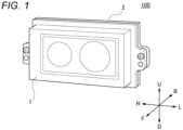
- FIG. 1 is a front perspective view illustrating configurations of a vehicle lamp 100 according to an embodiment of the present disclosure.
- the vehicle lamp 100 is a low-beam and high-beam front lamp to be mounted on a vehicle such as a motorcycle.
- the vehicle lamp 100 includes an outer lens 1 and a heat sink 2 to which the outer lens 1 is attached.
- a direction of an arrow F illustrated in FIG. 1 is “front”, and a direction of an arrow B is “rear”.
- a direction of an arrow R illustrated in FIG. 1 is “right”, and a direction of an arrow L is “left”.
- a direction of an arrow U illustrated in FIG. 1 is “upper”, and a direction of an arrow D is “lower”.
- FIG. 2 is an exploded perspective view illustrating detailed configurations of the vehicle lamp 100 illustrated in FIG. 1 .
- FIG. 2 does not illustrate the heat sink 2 illustrated in FIG. 1 .
- the vehicle lamp 100 includes a plurality of optical systems 20 in addition to the outer lens 1 and the heat sink 2.
- the vehicle lamp 100 includes, for example, as the optical system 20, a first optical system 20a that forms a low-beam distribution pattern including a cutoff line and a second optical system 20b that forms a high-beam distribution pattern.
- the first optical system 20a and the second optical system 20b are arranged, for example, side by side in a left-right direction.
- the vehicle lamp 100 further includes inner lenses 4a and 4b, an intermediate member 5, light emitting elements 6a and 6b, and a substrate 7.
- each of the inner lenses 4a and 4b is also referred to as an “inner lens 4".
- Each of the light emitting elements 6a and 6b is also referred to as a "light emitting element 6".
- the outer lens 1, the inner lens 4, the intermediate member 5, the light emitting element 6, and the substrate 7 are arranged in this order from a front side.
- the heat sink 2 illustrated in FIG. 1 is disposed on a rear side relative to the substrate 7.
- the inner lens 4a and the light emitting element 6a are included in the first optical system 20a.
- the inner lens 4b and the light emitting element 6b are included in the second optical system 20b.
- the light emitting element 6 is, for example, a white light emitting diode, and has a rectangular light emitting surface.
- the light emitting surface of the light emitting element 6 is provided on a front side, and a rear surface of the light emitting element 6 is supported by the substrate 7.
- the substrate 7 is supported by the heat sink 2 illustrated in FIG. 1 .
- the intermediate member 5 is formed with an opening 11 for each optical system. That is, the intermediate member 5 is formed with, as the opening 11, an opening 11a allowing light from the light emitting element 6a to enter the inner lens 4a and an opening 11b allowing light from the light emitting element 6b to enter the inner lens 4b.
- the intermediate member 5 further includes reflecting portions 12a and 12b that reflect light from the light emitting element 6a toward the inner lens 4a in a vicinity of the opening 11a.
- each of the reflecting portions 12a and 12b is also referred to as a "reflecting portion 12". Details of the reflecting portion 12 will be described later.
- the inner lens 4 is, for example, a projection lens.
- the inner lens 4 is a convex lens having a rear surface, which is an incident surface, being a flat surface and a front surface, which is an emitting surface, being curved and protruding forward.
- the inner lens 4a refracts light from the light emitting element 6a
- the inner lens 4b refracts light from the light emitting element 6b.
- the inner lens 4a and the inner lens 4b are formed of the same material and are integrated.
- the vehicle lamp 100 further includes a plateshaped coupling portion 8 formed of the same material as the inner lenses 4a and 4b.
- the front surfaces of the inner lenses 4a and 4b protrude to a front side relative to the coupling portion 8.
- the rear surfaces of the inner lenses 4a and 4b are formed in the same plane as a rear surface of the coupling portion 8.
- the intermediate member 5 is not limited to the configuration of having an opening for each optical system, and may have, for example, one opening coupling the opening 11a and the opening 11b. However, in this case, light from the light emitting element 6a may enter the inner lens 4b, and light from the light emitting element 6b may enter the inner lens 4a. For this reason, the intermediate member 5 preferably has an opening for each optical system.
- FIG. 3 is an enlarged view illustrating a detailed configuration of a part of an intermediate member illustrated in FIG. 2 .
- FIG. 3 illustrates a part of the intermediate member 5, the light emitting element 6a, and a part of the substrate 7 as viewed from a front side.
- the light emitting element 6a and a part of the substrate 7 are exposed from the opening 11a of the intermediate member 5.
- the reflecting portions 12a and 12b are provided respectively on an upper right side and an upper left side relative to the light emitting element 6a on a front surface of the intermediate member 5.
- FIG. 3 illustrates three light emitting elements 6a, and the number of light emitting elements 6a may be one, two, or four or more.
- the intermediate member 5 is provided with a region E for blocking unnecessary light toward a lower side relative to the low-beam distribution pattern.
- the region E is a part in a vicinity of a lower side of the opening 11a of the intermediate member 5.
- the reflecting portion 12 is preferably provided in a region other than the region E.
- the cutoff line is formed by refraction of light incident on a prescribed region of the inner lens 4a.
- the reflecting portion 12 is preferably disposed to be avoided from existing on a path of light that forms the cutoff line.
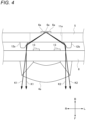
- FIG. 4 illustrates a path of light reflected by a reflecting portion among light emitted from a light emitting element illustrated in FIG. 3 .
- FIG. 4 illustrates a part of the intermediate member 5, the light emitting element 6a, the inner lens 4a, and a part of the coupling portion 8 as viewed from above.
- FIG. 5 illustrates a region illuminated with light reflected by the reflecting portion illustrated in FIG. 4 .
- FIG. 5 illustrates a road surface forward of a vehicle as viewed from a vehicle side.
- the light reaching the reflecting portion 12a provided on the upper right side relative to the light emitting element 6a may illuminate the left region X1 on the road surface in the vicinity of the vehicle
- the light reaching the reflecting portion 12b provided on the upper left side relative to the light emitting element 6a may illuminate the right region X2 on the road surface in the vicinity of the vehicle.
- the present disclosure is not limited to the configuration in which one reflecting portion 12 is provided on each of the upper right side and the upper left side relative to the light emitting element 6a, and the reflecting portion 12 may be provided on any one of the upper right side and the upper left side relative to the light emitting element 6a, or provided in other positions.
- the number of reflecting portions 12 may be one or three or more.
- the intermediate member 5 may not include the reflecting portion 12.
- the inner lens 4a includes light diffusing portions 13 that diffuse light emitted from the light emitting element 6a to an incident surface of the light, that is, a part of the rear surface.
- the light diffusing portion 13 is preferably disposed to be avoided from existing on the path of light that forms the cutoff line.
- the light diffusing portion 13 may be subjected to, for example, an embossing treatment or a frost treatment.
- a blockshaped member or the like may be provided as the light diffusing portion 13.
- FIG. 6 illustrates a path of light passing through a light diffusing portion of an inner lens among light emitted from the light emitting element illustrated in FIG. 3 . Similar to FIG. 4 , FIG. 6 illustrates a part of the intermediate member 5, the light emitting element 6a, the inner lens 4a, and a part of the coupling portion 8 as viewed from above.
- light reaching the light diffusing portion 13 is diffused by the light diffusing portion 13, enters the inner lens 4a, and is emitted from the inner lens 4a, as indicated by arrows K3. Accordingly, direct light from the light emitting element 6a can be effectively diffused and unevenness of light in an illumination region can be further reduced.
- a step may be provided on the incident surface of the inner lens 4a on a lower side relative to the light emitting element 6a in a front view of the vehicle lamp 100.
- the step is preferably disposed to be avoided from existing on the path of light that forms the cutoff line.
- the light diffusing portion 13 is not limited to the configuration of diffusing direct light emitted from the light emitting element 6a as illustrated in FIG. 6 .
- the light diffusing portion 13 may diffuse light reflected by the reflecting portion 12.
- the first optical system 20a and the second optical system 20b are not limited to respectively forming the low-beam distribution pattern and the high-beam distribution pattern.
- both the first optical system 20a and the second optical system 20b may form a low-beam distribution pattern.
- the reflecting portion 12 is preferably provided not only in the vicinity of the opening 11a of the intermediate member 5 but also in a vicinity of the opening 11b.
- the light diffusing portion 13 preferably diffuses light from the light emitting element 6b not only on the incident surface of the inner lens 4a but also on the incident surface of the inner lens 4b.
- the vehicle lamp 100 is not limited to the configuration of including two optical systems, and may include three or more optical systems.
- a plurality of optical systems are not limited to being arranged side by side in the left-right direction, and may be provided side by side in an upper-lower direction, for example.
- the vehicle lamp 100 is not limited to the configuration of including the intermediate member 5, and may not include the intermediate member 5.
- the vehicle lamp 100 includes a plurality of optical systems 20, each of the plurality of optical systems 20 includes the light emitting element 6 and the inner lens 4 disposed on a front side relative to the light emitting element 6, and the plurality of inner lenses 4 are integrated.
- the number of components can be reduced, cost can be reduced, and assembly can be facilitated.
- At least one of the plurality of inner lenses 4 includes the light diffusing portion 13 on a part of an incident surface on which the light from the light emitting element 6 is incident, and the light diffusing portion 30 is configured to diffuse the light.
- the substrate 7 supports the light emitting element 6.
- the intermediate member 5 is disposed between the substrate 7 and the inner lens 4.
- the intermediate member 5 includes the reflecting portion 12 configured to reflect light from the light emitting element 6a toward the inner lens 4a.
- the reflecting portion 12 is provided on at least one of the upper right side and the upper left side relative to the light emitting element 6a.
- the intermediate member 5 is formed with, for each optical system 20, the opening 11 for allowing the light from the light emitting element 6 to enter the inner lens 4.
- the intermediate member 5 can not only reflect the light from the light emitting element 6 toward the inner lens 4 by the reflecting portion 12, but also prevent the light from the light emitting element 6 from entering the inner lens 4 not corresponding to the light emitting element 6.
- the configuration in which the plurality of inner lenses 4 are integrated is particularly effective.
- the light emitting element 6 and the inner lens 4 are provided in the optical system 20 to form a light distribution pattern including a cutoff line.
- the reflecting portion 12 in the intermediate member 5 is disposed to be avoided from existing on the path of light forming the cutoff line.
Landscapes
- Engineering & Computer Science (AREA)
- General Engineering & Computer Science (AREA)
- Physics & Mathematics (AREA)
- Microelectronics & Electronic Packaging (AREA)
- Optics & Photonics (AREA)
- Geometry (AREA)
- Non-Portable Lighting Devices Or Systems Thereof (AREA)
Abstract
Description
- The present disclosure relates to a vehicle lamp to be mounted on a vehicle.
- Techniques relating to a vehicle lamp are being developed in the related art. For example, a vehicle lamp disclosed in
Patent Literature 1 is a front lamp for a two-wheeled vehicle, which includes a first lamp unit that forms a high-beam distribution pattern, a second lamp unit that forms a low-beam distribution pattern, and a panel member surrounding the first lamp unit and the second lamp unit. The first lamp unit and the second lamp unit have separate inner lenses. - Patent Literature 1:
JP2015-076364A - As in the vehicle lamp described in
Patent Literature 1, a lamp including a plurality of inner lenses tends to have an increased number of components. - An object of the present disclosure is to provide a vehicle lamp that can achieve a reduced number of components, reduced cost, and facilitated assembly.
- A vehicle lamp according to an aspect of the present disclosure is a vehicle front lamp configured to be mounted on a vehicle, the vehicle front lamp including a plurality of optical systems, each of the plurality of optical systems including a light emitting element and an inner lens disposed on a front side relative to the light emitting element. The plurality of inner lenses are integrated.
- According to the present disclosure, it is possible to achieve a reduced number of components, reduced cost, and facilitated assembly.
-
- [
FIG. 1] FIG. 1 is a front perspective view illustrating configurations of a vehicle lamp according to an embodiment of the present disclosure. - [
FIG. 2] FIG. 2 is an exploded perspective view illustrating detailed configurations of the vehicle lamp illustrated inFIG. 1 . - [
FIG. 3] FIG. 3 is an enlarged view illustrating a detailed configuration of a part of an intermediate member illustrated inFIG. 2 . - [
FIG. 4] FIG. 4 illustrates a path of light reflected by a reflecting portion among light emitted from a light emitting element illustrated inFIG. 3 . - [
FIG. 5] FIG. 5 illustrates a region illuminated with light reflected by the reflecting portion illustrated inFIG. 4 . - [
FIG. 6] FIG. 6 illustrates a path of light passing through a light diffusing portion of an inner lens among light emitted from the light emitting element illustrated inFIG. 3 . - The present disclosure will be described with reference to the drawings.
FIG. 1 is a front perspective view illustrating configurations of avehicle lamp 100 according to an embodiment of the present disclosure. - Referring to
FIG. 1 , thevehicle lamp 100 is a low-beam and high-beam front lamp to be mounted on a vehicle such as a motorcycle. Thevehicle lamp 100 includes anouter lens 1 and aheat sink 2 to which theouter lens 1 is attached. - In this example, a direction of an arrow F illustrated in
FIG. 1 is "front", and a direction of an arrow B is "rear". A direction of an arrow R illustrated inFIG. 1 is "right", and a direction of an arrow L is "left". A direction of an arrow U illustrated inFIG. 1 is "upper", and a direction of an arrow D is "lower". -
FIG. 2 is an exploded perspective view illustrating detailed configurations of thevehicle lamp 100 illustrated inFIG. 1 .FIG. 2 does not illustrate theheat sink 2 illustrated inFIG. 1 . Referring toFIGS. 1 and2 , thevehicle lamp 100 includes a plurality ofoptical systems 20 in addition to theouter lens 1 and theheat sink 2. - Specifically, the
vehicle lamp 100 includes, for example, as theoptical system 20, a firstoptical system 20a that forms a low-beam distribution pattern including a cutoff line and a secondoptical system 20b that forms a high-beam distribution pattern. The firstoptical system 20a and the secondoptical system 20b are arranged, for example, side by side in a left-right direction. - More specifically, the
vehicle lamp 100 further includesinner lenses intermediate member 5,light emitting elements substrate 7. Hereinafter, each of theinner lenses inner lens 4". Each of thelight emitting elements light emitting element 6". - The
outer lens 1, theinner lens 4, theintermediate member 5, thelight emitting element 6, and thesubstrate 7 are arranged in this order from a front side. Theheat sink 2 illustrated inFIG. 1 is disposed on a rear side relative to thesubstrate 7. Theinner lens 4a and thelight emitting element 6a are included in the firstoptical system 20a. Theinner lens 4b and thelight emitting element 6b are included in the secondoptical system 20b. - The
light emitting element 6 is, for example, a white light emitting diode, and has a rectangular light emitting surface. The light emitting surface of thelight emitting element 6 is provided on a front side, and a rear surface of thelight emitting element 6 is supported by thesubstrate 7. Thesubstrate 7 is supported by theheat sink 2 illustrated inFIG. 1 . - The
intermediate member 5 is formed with anopening 11 for each optical system. That is, theintermediate member 5 is formed with, as theopening 11, an opening 11a allowing light from thelight emitting element 6a to enter theinner lens 4a and an opening 11b allowing light from thelight emitting element 6b to enter theinner lens 4b. - The
intermediate member 5 further includes reflectingportions light emitting element 6a toward theinner lens 4a in a vicinity of the opening 11a. Hereinafter, each of the reflectingportions portion 12". Details of the reflectingportion 12 will be described later. - The
inner lens 4 is, for example, a projection lens. Specifically, theinner lens 4 is a convex lens having a rear surface, which is an incident surface, being a flat surface and a front surface, which is an emitting surface, being curved and protruding forward. Theinner lens 4a refracts light from thelight emitting element 6a, and theinner lens 4b refracts light from thelight emitting element 6b. Theinner lens 4a and theinner lens 4b are formed of the same material and are integrated. - More specifically, for example, the
vehicle lamp 100 further includes aplateshaped coupling portion 8 formed of the same material as theinner lenses inner lenses coupling portion 8. The rear surfaces of theinner lenses coupling portion 8. - The
intermediate member 5 is not limited to the configuration of having an opening for each optical system, and may have, for example, one opening coupling the opening 11a and the opening 11b. However, in this case, light from thelight emitting element 6a may enter theinner lens 4b, and light from thelight emitting element 6b may enter theinner lens 4a. For this reason, theintermediate member 5 preferably has an opening for each optical system. -
FIG. 3 is an enlarged view illustrating a detailed configuration of a part of an intermediate member illustrated inFIG. 2 .FIG. 3 illustrates a part of theintermediate member 5, thelight emitting element 6a, and a part of thesubstrate 7 as viewed from a front side. - Referring to
FIG. 3 , thelight emitting element 6a and a part of thesubstrate 7 are exposed from the opening 11a of theintermediate member 5. The reflectingportions light emitting element 6a on a front surface of theintermediate member 5.FIG. 3 illustrates three light emittingelements 6a, and the number oflight emitting elements 6a may be one, two, or four or more. - More specifically, the
intermediate member 5 is provided with a region E for blocking unnecessary light toward a lower side relative to the low-beam distribution pattern. Specifically, the region E is a part in a vicinity of a lower side of theopening 11a of theintermediate member 5. The reflectingportion 12 is preferably provided in a region other than the region E. The cutoff line is formed by refraction of light incident on a prescribed region of theinner lens 4a. The reflectingportion 12 is preferably disposed to be avoided from existing on a path of light that forms the cutoff line. -
FIG. 4 illustrates a path of light reflected by a reflecting portion among light emitted from a light emitting element illustrated inFIG. 3 .FIG. 4 illustrates a part of theintermediate member 5, thelight emitting element 6a, theinner lens 4a, and a part of thecoupling portion 8 as viewed from above.FIG. 5 illustrates a region illuminated with light reflected by the reflecting portion illustrated inFIG. 4 .FIG. 5 illustrates a road surface forward of a vehicle as viewed from a vehicle side. - Referring to
FIGS. 4 and5 , among light from thelight emitting element 6a, light reaching the reflectingportion 12a provided on the upper right side relative to thelight emitting element 6a is reflected by the reflectingportion 12a and enters theinner lens 4a as indicated by arrows K1. Then, as illustrated inFIG. 5 , the light illuminates a right region X2 on the road surface in a vicinity and forward of the vehicle. - Light reaching the reflecting
portion 12b provided on the upper left side relative to thelight emitting element 6a is reflected by the reflectingportion 12b and enters theinner lens 4a as indicated by arrows K2 inFIG. 4 . Then, as illustrated inFIG. 5 , the light illuminates a left region X1 on the road surface in the vicinity and forward of the vehicle. Accordingly, visibility on the road surface in the vicinity and forward of the vehicle can be improved. - Among the light from the
light emitting element 6a, the light reaching the reflectingportion 12a provided on the upper right side relative to thelight emitting element 6a may illuminate the left region X1 on the road surface in the vicinity of the vehicle, and the light reaching the reflectingportion 12b provided on the upper left side relative to thelight emitting element 6a may illuminate the right region X2 on the road surface in the vicinity of the vehicle. - Alternatively, the present disclosure is not limited to the configuration in which one reflecting
portion 12 is provided on each of the upper right side and the upper left side relative to thelight emitting element 6a, and the reflectingportion 12 may be provided on any one of the upper right side and the upper left side relative to thelight emitting element 6a, or provided in other positions. The number of reflectingportions 12 may be one or three or more. Theintermediate member 5 may not include the reflectingportion 12. - Referring again to
FIG. 4 , theinner lens 4a includeslight diffusing portions 13 that diffuse light emitted from thelight emitting element 6a to an incident surface of the light, that is, a part of the rear surface. Thelight diffusing portion 13 is preferably disposed to be avoided from existing on the path of light that forms the cutoff line. Thelight diffusing portion 13 may be subjected to, for example, an embossing treatment or a frost treatment. A blockshaped member or the like may be provided as thelight diffusing portion 13. -
FIG. 6 illustrates a path of light passing through a light diffusing portion of an inner lens among light emitted from the light emitting element illustrated inFIG. 3 . Similar toFIG. 4 ,FIG. 6 illustrates a part of theintermediate member 5, thelight emitting element 6a, theinner lens 4a, and a part of thecoupling portion 8 as viewed from above. - Referring to
FIG. 6 , among light from thelight emitting element 6a, light reaching thelight diffusing portion 13 is diffused by thelight diffusing portion 13, enters theinner lens 4a, and is emitted from theinner lens 4a, as indicated by arrows K3. Accordingly, direct light from thelight emitting element 6a can be effectively diffused and unevenness of light in an illumination region can be further reduced. - Further, a step (not illustrated) may be provided on the incident surface of the
inner lens 4a on a lower side relative to thelight emitting element 6a in a front view of thevehicle lamp 100. In this case, among the light from thelight emitting element 6a, light reaching the step is reflected by the step and is emitted forward and upward from theinner lens 4a. Accordingly, the light can illuminate a signboard or the like located forward and upward of the vehicle on which thevehicle lamp 100 is mounted. Similar to thelight diffusing portion 13, the step is preferably disposed to be avoided from existing on the path of light that forms the cutoff line. - The
light diffusing portion 13 is not limited to the configuration of diffusing direct light emitted from thelight emitting element 6a as illustrated inFIG. 6 . For example, thelight diffusing portion 13 may diffuse light reflected by the reflectingportion 12. - The first
optical system 20a and the secondoptical system 20b are not limited to respectively forming the low-beam distribution pattern and the high-beam distribution pattern. For example, both the firstoptical system 20a and the secondoptical system 20b may form a low-beam distribution pattern. In this case, the reflectingportion 12 is preferably provided not only in the vicinity of theopening 11a of theintermediate member 5 but also in a vicinity of theopening 11b. In this case, thelight diffusing portion 13 preferably diffuses light from thelight emitting element 6b not only on the incident surface of theinner lens 4a but also on the incident surface of theinner lens 4b. - The
vehicle lamp 100 is not limited to the configuration of including two optical systems, and may include three or more optical systems. A plurality of optical systems are not limited to being arranged side by side in the left-right direction, and may be provided side by side in an upper-lower direction, for example. Thevehicle lamp 100 is not limited to the configuration of including theintermediate member 5, and may not include theintermediate member 5. - As described above, the
vehicle lamp 100 according to the embodiment of the present disclosure includes a plurality ofoptical systems 20, each of the plurality ofoptical systems 20 includes thelight emitting element 6 and theinner lens 4 disposed on a front side relative to thelight emitting element 6, and the plurality ofinner lenses 4 are integrated. With such a configuration, compared to a case in which theinner lenses 4 are separately provided for eachoptical system 20, the number of components can be reduced, cost can be reduced, and assembly can be facilitated. - In the
vehicle lamp 100 according to the embodiment of the present disclosure, at least one of the plurality ofinner lenses 4 includes thelight diffusing portion 13 on a part of an incident surface on which the light from thelight emitting element 6 is incident, and the light diffusing portion 30 is configured to diffuse the light. With such a configuration, direct light from thelight emitting element 6 can be effectively diffused and unevenness of light in an illumination region can be further reduced. - In the
vehicle lamp 100 according to the embodiment of the present disclosure, thesubstrate 7 supports thelight emitting element 6. Theintermediate member 5 is disposed between thesubstrate 7 and theinner lens 4. Theintermediate member 5 includes the reflectingportion 12 configured to reflect light from thelight emitting element 6a toward theinner lens 4a. The reflectingportion 12 is provided on at least one of the upper right side and the upper left side relative to thelight emitting element 6a. With such a configuration, at least one of a left region and a right region on the road surface in the vicinity and forward of the vehicle is illuminated by appropriate light, and visibility on the road surface in the vicinity and forward of the vehicle can be further improved. - In the
vehicle lamp 100 according to the embodiment of the present disclosure, theintermediate member 5 is formed with, for eachoptical system 20, theopening 11 for allowing the light from thelight emitting element 6 to enter theinner lens 4. With such a configuration, theintermediate member 5 can not only reflect the light from thelight emitting element 6 toward theinner lens 4 by the reflectingportion 12, but also prevent the light from thelight emitting element 6 from entering theinner lens 4 not corresponding to thelight emitting element 6. As described above, the configuration in which the plurality ofinner lenses 4 are integrated is particularly effective. - In the
vehicle lamp 100 according to the embodiment of the present disclosure, thelight emitting element 6 and theinner lens 4 are provided in theoptical system 20 to form a light distribution pattern including a cutoff line. The reflectingportion 12 in theintermediate member 5 is disposed to be avoided from existing on the path of light forming the cutoff line. With such a configuration, visibility on the road surface in the vicinity and forward of the vehicle can be further improved, and the cutoff line can be prevented from being not clear. - Although the embodiment of the present disclosure is described above, it is needless to say that the technical scope of the present disclosure should not be construed as being limited by the description of the embodiment. It should be understood by a person skilled in the art that the present embodiment is merely an example, and that various modifications of the embodiment are possible within the scope of the inventions described in the claims. The technical scope of the present disclosure is determined based on the scope of the inventions described in the claims and an equivalent scope thereof.
- The present application is based on a
Japanese patent application No. 2022-060196 filed on March 31, 2022
Claims (5)
- A vehicle front lamp configured to be mounted on a vehicle, the vehicle front lamp comprising:a plurality of optical systems, each of the plurality of optical systems comprising a light emitting element and an inner lens disposed on a front side relative to the light emitting element,wherein the plurality of inner lenses are integrated.
- The vehicle front lamp according to claim 1, wherein at least one of the plurality of inner lenses comprises a light diffusing portion on a part of an incident surface on which light from the light emitting element is incident, the light diffusing portion being configured to diffuse the light.
- The vehicle front lamp according to claim 1 or 2, further comprising:a substrate supporting the light emitting element; andan intermediate member disposed between the substrate and the inner lens,wherein the intermediate member comprises a reflecting portion configured to reflect light from the light emitting element toward the inner lens, andwherein the reflecting portion is provided on at least one of an upper right side and an upper left side relative to the light emitting element.
- The vehicle front lamp according to claim 3, wherein the intermediate member is formed with, for each of the optical systems, an opening allowing the light from the light emitting element to enter the inner lens.
- The vehicle front lamp according to claim 3 or 4,wherein in each of the optical systems, the light emitting element and the inner lens are disposed to form at least a light distribution pattern including a cutoff line, andwherein the reflecting portion provided on the intermediate member is disposed to be avoided from existing on a path of light forming the cutoff line.
Applications Claiming Priority (2)
| Application Number | Priority Date | Filing Date | Title |
|---|---|---|---|
| JP2022060196 | 2022-03-31 | ||
| PCT/JP2023/011292 WO2023189960A1 (en) | 2022-03-31 | 2023-03-22 | Vehicle lamp |
Publications (2)
| Publication Number | Publication Date |
|---|---|
| EP4502458A1 true EP4502458A1 (en) | 2025-02-05 |
| EP4502458A4 EP4502458A4 (en) | 2025-07-16 |
Family
ID=88201880
Family Applications (1)
| Application Number | Title | Priority Date | Filing Date |
|---|---|---|---|
| EP23779972.1A Pending EP4502458A4 (en) | 2022-03-31 | 2023-03-22 | VEHICLE LIGHT |
Country Status (5)
| Country | Link |
|---|---|
| US (1) | US20250224092A1 (en) |
| EP (1) | EP4502458A4 (en) |
| JP (1) | JPWO2023189960A1 (en) |
| CN (1) | CN119173720A (en) |
| WO (1) | WO2023189960A1 (en) |
Family Cites Families (14)
| Publication number | Priority date | Publication date | Assignee | Title |
|---|---|---|---|---|
| JP5442463B2 (en) * | 2010-01-12 | 2014-03-12 | 株式会社小糸製作所 | Vehicle headlamp |
| JP5945125B2 (en) * | 2012-02-07 | 2016-07-05 | 株式会社小糸製作所 | Vehicle lighting |
| CN104169641B (en) * | 2012-03-15 | 2016-08-31 | 株式会社小糸制作所 | Light-emitting device and lamps apparatus for vehicle |
| JP6261276B2 (en) | 2013-10-11 | 2018-01-17 | 株式会社小糸製作所 | Vehicle lighting |
| JP6430120B2 (en) * | 2014-01-23 | 2018-11-28 | 株式会社小糸製作所 | Motorcycle headlights |
| JP6709655B2 (en) * | 2016-03-25 | 2020-06-17 | 株式会社小糸製作所 | Vehicle lamp and vehicle equipped with the vehicle lamp |
| JP6709654B2 (en) * | 2016-03-25 | 2020-06-17 | 株式会社小糸製作所 | Vehicle lamp and vehicle equipped with the vehicle lamp |
| JP6722030B2 (en) * | 2016-04-19 | 2020-07-15 | スタンレー電気株式会社 | Vehicle lighting |
| FR3051884A1 (en) * | 2016-05-27 | 2017-12-01 | Koito Mfg Co Ltd | VEHICLE LAMP |
| JP2018092883A (en) * | 2016-11-25 | 2018-06-14 | 株式会社小糸製作所 | Vehicular lighting fixture |
| JP2019061905A (en) * | 2017-09-27 | 2019-04-18 | パナソニックIpマネジメント株式会社 | Moving body illuminating device and moving body |
| JP7231700B2 (en) | 2018-02-20 | 2023-03-01 | マクセル株式会社 | small electrical equipment |
| JP7479192B2 (en) * | 2020-05-14 | 2024-05-08 | スタンレー電気株式会社 | Vehicle lighting fixtures |
| JP7447698B2 (en) * | 2020-06-24 | 2024-03-12 | 市光工業株式会社 | Vehicle lights |
-
2023
- 2023-03-22 EP EP23779972.1A patent/EP4502458A4/en active Pending
- 2023-03-22 JP JP2024512225A patent/JPWO2023189960A1/ja active Pending
- 2023-03-22 WO PCT/JP2023/011292 patent/WO2023189960A1/en not_active Ceased
- 2023-03-22 CN CN202380032205.5A patent/CN119173720A/en active Pending
- 2023-03-22 US US18/852,864 patent/US20250224092A1/en not_active Abandoned
Also Published As
| Publication number | Publication date |
|---|---|
| JPWO2023189960A1 (en) | 2023-10-05 |
| CN119173720A (en) | 2024-12-20 |
| US20250224092A1 (en) | 2025-07-10 |
| WO2023189960A1 (en) | 2023-10-05 |
| EP4502458A4 (en) | 2025-07-16 |
Similar Documents
| Publication | Publication Date | Title |
|---|---|---|
| US6805476B2 (en) | Led-type vehicular lamp having uniform brightness | |
| US10310158B2 (en) | Vehicle lighting device wherein a light guide supports another light guide | |
| EP2166279B1 (en) | Vehicle headlamp | |
| US7736039B2 (en) | Vehicle lamp | |
| US8007149B2 (en) | Vehicle lighting assembly and light guiding lens for use in vehicle lighting assembly | |
| JP3195294B2 (en) | Vehicle lighting | |
| CN112781004A (en) | Vehicle lamps | |
| JP5563209B2 (en) | Lamp | |
| US6543923B2 (en) | Vehicle lamp | |
| RU2507442C2 (en) | Light device for vehicle | |
| US8752991B2 (en) | Vehicle lighting device | |
| US20170241616A1 (en) | Vehicle lighting fixture | |
| CN112135998A (en) | Vehicle lamps | |
| EP3228924B1 (en) | Vehicle lamp | |
| JP2005251435A (en) | Vehicle headlamp | |
| US20190120453A1 (en) | Vehicular lamp | |
| US10865956B1 (en) | Vehicle light | |
| KR20180078729A (en) | Lamp for vehicle | |
| US20250224092A1 (en) | Vehicle lamp | |
| JP6648428B2 (en) | Vehicle lighting | |
| US20250147399A1 (en) | Optical member, light source device, and head-up display | |
| JP6052599B2 (en) | Vehicle headlamp | |
| KR20250058451A (en) | Lamp for vehicle and vehicle including the same | |
| US12090915B2 (en) | Lamp for vehicle | |
| US10883688B2 (en) | Lamp device for vehicle |
Legal Events
| Date | Code | Title | Description |
|---|---|---|---|
| STAA | Information on the status of an ep patent application or granted ep patent |
Free format text: STATUS: THE INTERNATIONAL PUBLICATION HAS BEEN MADE |
|
| PUAI | Public reference made under article 153(3) epc to a published international application that has entered the european phase |
Free format text: ORIGINAL CODE: 0009012 |
|
| STAA | Information on the status of an ep patent application or granted ep patent |
Free format text: STATUS: REQUEST FOR EXAMINATION WAS MADE |
|
| 17P | Request for examination filed |
Effective date: 20240930 |
|
| AK | Designated contracting states |
Kind code of ref document: A1 Designated state(s): AL AT BE BG CH CY CZ DE DK EE ES FI FR GB GR HR HU IE IS IT LI LT LU LV MC ME MK MT NL NO PL PT RO RS SE SI SK SM TR |
|
| DAV | Request for validation of the european patent (deleted) | ||
| DAX | Request for extension of the european patent (deleted) | ||
| A4 | Supplementary search report drawn up and despatched |
Effective date: 20250616 |
|
| RIC1 | Information provided on ipc code assigned before grant |
Ipc: F21S 41/265 20180101AFI20250610BHEP Ipc: F21S 41/143 20180101ALI20250610BHEP Ipc: F21S 41/151 20180101ALI20250610BHEP Ipc: F21S 41/255 20180101ALI20250610BHEP Ipc: F21S 41/275 20180101ALI20250610BHEP Ipc: F21S 41/32 20180101ALI20250610BHEP Ipc: F21S 41/39 20180101ALI20250610BHEP Ipc: F21S 41/43 20180101ALI20250610BHEP Ipc: F21S 41/47 20180101ALI20250610BHEP Ipc: F21W 102/135 20180101ALI20250610BHEP Ipc: F21Y 115/10 20160101ALI20250610BHEP |
|
| STAA | Information on the status of an ep patent application or granted ep patent |
Free format text: STATUS: THE APPLICATION IS DEEMED TO BE WITHDRAWN |