EP4502426A1 - Magnetic gear and magnetic-geared electric machine - Google Patents
Magnetic gear and magnetic-geared electric machine Download PDFInfo
- Publication number
- EP4502426A1 EP4502426A1 EP23807240.9A EP23807240A EP4502426A1 EP 4502426 A1 EP4502426 A1 EP 4502426A1 EP 23807240 A EP23807240 A EP 23807240A EP 4502426 A1 EP4502426 A1 EP 4502426A1
- Authority
- EP
- European Patent Office
- Prior art keywords
- magnetic pole
- magnets
- pole piece
- circumferential direction
- magnetic
- Prior art date
- Legal status (The legal status is an assumption and is not a legal conclusion. Google has not performed a legal analysis and makes no representation as to the accuracy of the status listed.)
- Pending
Links
Images










Classifications
-
- H—ELECTRICITY
- H02—GENERATION; CONVERSION OR DISTRIBUTION OF ELECTRIC POWER
- H02K—DYNAMO-ELECTRIC MACHINES
- H02K49/00—Dynamo-electric clutches; Dynamo-electric brakes
- H02K49/10—Dynamo-electric clutches; Dynamo-electric brakes of the permanent-magnet type
- H02K49/102—Magnetic gearings, i.e. assembly of gears, linear or rotary, by which motion is magnetically transferred without physical contact
-
- H—ELECTRICITY
- H02—GENERATION; CONVERSION OR DISTRIBUTION OF ELECTRIC POWER
- H02K—DYNAMO-ELECTRIC MACHINES
- H02K2213/00—Specific aspects, not otherwise provided for and not covered by codes H02K2201/00 - H02K2211/00
- H02K2213/03—Machines characterised by numerical values, ranges, mathematical expressions or similar information
Definitions
- the present disclosure relates to a magnetic gear and a magnetic geared electrical machine.
- the magnetic geared electrical machine includes a magnetic gear unit for transmitting a magnetic torque.
- the magnetic gear unit exemplified in PTL 1 includes an outer rotor, a magnetic pole piece module, and an inner rotor in order from the outside in the radial direction.
- the outer rotor includes a plurality of outer magnets arranged in the circumferential direction
- the inner rotor includes a plurality of inner magnets arranged in the circumferential direction.
- the plurality of outer magnets and the plurality of inner magnets are permanent magnets.
- the amount of change (gradient) in the rotational direction of the magnetomotive force caused by the permanent magnet contributes to the transmission torque of the magnetic gear unit.
- the transmission torque further includes a magnetic reluctance torque for bringing the tooth portion and the magnetic pole piece closer to each other in the rotational direction. In such a configuration, it is desired to further improve the transmission torque.
- the present disclosure provides a magnetic gear and a magnetic geared electrical machine having a tooth portion protruding toward a magnetic pole piece and supporting magnets to improve transmission torque.
- a magnetic gear and a magnetic geared electrical machine having a tooth portion protruding toward a magnetic pole piece and supporting a magnet to improve transmission torque.
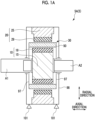
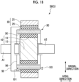
- Figs. 1A and 1B are schematic diagrams of a magnetic gear 5 according to some embodiments of the present disclosure.
- an "axial direction” is a direction parallel to a rotation axis (the first rotation axis A1 or the second rotation axis A2) of the magnetic gear 5
- a "radial direction” is a direction orthogonal to the rotation axis of the magnetic gear 5
- a “circumferential direction” is a circumferential direction based on the rotation axis of the magnetic gear 5.
- the circumferential length of a component of the magnetic gear 5 may be simply referred to as the circumferential length of the component.
- Each of the magnetic gears 5 shown in Figs. 1A and 1B includes a first yoke unit 10, a second yoke unit 20, and a magnetic pole piece unit 30 in order from one side in the radial direction. These three units all extend in the axial direction.
- the first yoke unit 10 includes a plurality of first magnets 19 arranged in the circumferential direction and a first yoke 15 supporting the plurality of first magnets 19.
- the second yoke unit 20 includes a plurality of second magnets 29 arranged in the circumferential direction and a second yoke 25 supporting the plurality of second magnets 29.
- the magnetic pole piece unit 30 includes a plurality of magnetic pole pieces 50 arranged in the circumferential direction, and the plurality of magnetic pole pieces 50 face each of the plurality of first magnets 19 and the plurality of second magnets 29 between the first yoke unit 10 and the second yoke unit 20 with gaps G1 and G2 (see Fig. 2A , for example) therebetween.
- One of the first yoke unit 10, the second yoke unit 20, and the magnetic pole piece unit 30 functions as a stator, and the remaining two function as rotors.
- the number of the second magnets 29 is larger than the number of the magnetic pole pieces 50, and the number of the magnetic pole pieces 50 is larger than the number of the first magnets 19.
- the circumferential length of the first magnet 19 is longer than the circumferential length of the second magnet 29.
- the second yoke unit 20 is disposed on the outer circumferential side of the first yoke unit 10. That is, the magnetic gear 5 includes the first yoke unit 10, the magnetic pole piece unit 30, and the second yoke unit 20 in order from the inner side (inner circumferential side) in the radial direction.
- the second yoke unit 20 may be disposed on the inner circumferential side of the first yoke unit 10, that is, the magnetic gear 5 may include the first yoke unit 10, the magnetic pole piece unit 30, and the second yoke unit 20 in order from the outer side (outer circumferential side) in the radial direction (see Figs. 2B and 2D ).
- the magnetic gear 5A (5) shown in Fig. 1A includes a housing 98 which may be mounted on a base 101.
- the second yoke unit 20 functions as a stator.
- the housing 98 rotatably supports the first rotation axis A1, which may function as an input shaft, via a bearing.
- Both axial ends of the magnetic pole piece unit 30 are coupled to the pair of end plates 97, respectively.
- One of the end plates 97 is coupled to the first rotation axis A1, and the other end plate 97 is coupled via a bearing to the second rotation axis A2 disposed coaxially with the first rotation axis A1.
- the magnetic pole piece unit 30 shown in the same drawing functions as a rotor that rotates together with the first rotation axis A1.
- the second rotation axis A2 of the present example which may function as an output shaft, supports the first yoke unit 10 disposed between the pair of end plates 97. Therefore, the first yoke unit 10 shown in the same drawing functions as a rotor that rotates together with the second rotation axis A2.
- the second rotation axis A2 is rotatably supported by the housing 98 via a bearing. One end portion of the second rotation axis A2 may be coupled to the first rotation axis A1 via a bearing or may not be coupled to the first rotation axis A1.
- the magnetic gear 5A operates as follows, for example.
- the first rotation axis A1 as the input shaft rotates together with the magnetic pole piece unit 30, the plurality of magnetic pole pieces 50 rotate relative to the plurality of first magnets 19 and the plurality of second magnets 29.
- the magnetic flux flowing through the magnetic pole piece unit 30 between the first yoke unit 10 and the second yoke unit 20 changes, and the first yoke unit 10 rotates in a direction in which the magnitude of the magnetic flux of the first magnet 19 increases.
- the second rotation axis A2 as the output shaft rotates.
- the second rotation axis A2 may function as an input shaft, and the first rotation axis A1 may function as an output shaft.
- the plurality of magnetic pole pieces 50 rotate relative to the plurality of first magnets 19.
- the magnetic flux flowing through the magnetic pole piece unit 30 between the first yoke unit 10 and the second yoke unit 20 changes, and the magnetic pole piece unit 30 rotates in a direction in which the magnitude of the magnetic flux flowing through the magnetic pole piece unit 30 increases. Accordingly, the first rotation axis A1 as the output shaft rotates.
- NL/NH is greater than 1
- the first yoke unit 10 functions as a high-speed rotor
- the magnetic pole piece unit 30 functions as a low-speed rotor.
- the number NL of magnetic poles of the magnetic pole piece 50 is smaller than the number NS of magnetic poles of the second magnet 29.
- the magnetic pole piece unit 30 functions as a stator, and the first yoke unit 10 and the second yoke unit 20 function as a rotor.
- the magnetic gear 5B includes a housing 96 which may be mounted on the base 101 and by which the magnetic pole piece unit 30 is supported.
- the housing 96 rotatably supports a second rotation axis A2 that may function as an output shaft via a bearing.
- the first rotation axis A1 which is disposed coaxially with the second rotation axis A2 and may function as an input shaft, is rotatably supported by a support unit (not shown) and is coupled to the second yoke unit 20 via a coupling member 95.
- the second yoke unit 20 may be coupled to the magnetic pole piece unit 30 via a bearing.
- the second rotation axis A2 may be coupled to the first rotation axis A1 via a bearing, or may not be coupled to the first rotation axis A1.
- the magnetic gear 5B operates as follows, for example.
- the first rotation axis A1 as the input shaft rotates together with the second yoke unit 20
- the plurality of magnetic pole pieces 50 rotate relative to the plurality of second magnets 29.
- the magnetic flux flowing through the magnetic pole piece unit 30 between the first yoke unit 10 and the second yoke unit 20 changes, and the first yoke unit 10 rotates in a direction in which the magnitude of the magnetic flux flowing through the first magnet 19 increases.
- the second rotation axis A2 as the output shaft rotates.
- the second rotation axis A2 may function as an input shaft
- the first rotation axis A1 may function as an output shaft.
- the plurality of magnetic pole pieces 50 rotate relative to the plurality of first magnets 19.
- the magnetic flux flowing through the magnetic pole piece unit 30 between the first yoke unit 10 and the second yoke unit 20 changes, and the second yoke unit 20 rotates in a direction in which the magnitude of the magnetic flux flowing through the second magnet 29 increases. Accordingly, the first rotation axis A1 as the output shaft rotates.
- the magnetic gear 5 shown in Fig. 1A and Fig. 1B can also be incorporated into a magnetic geared electrical machine 1 described below, which may be, for example, a magnetic geared generator 2 or a magnetic geared motor 3 (see Figs. 11A to 11D ).
- a magnetic geared electrical machine 1 is a magnetic geared generator 2
- the first rotation axis A1 or the second rotation axis A2 functioning as an output shaft may not be provided.
- the magnetic geared electrical machine 1 is the magnetic geared motor 3
- the first rotation axis A1 or the second rotation axis A2 functioning as the input shaft may not be provided.
- the first rotation axis A1 and the second rotation axis A2 may be provided with a single rotation axis.
- one rotation axis may be rotatably supported by the housing 98 (see Fig. 1A ) and may be rotatably coupled to the first yoke unit 10, and each of the pair of end plates 97 may be fixed to the outer peripheral portion of the rotating axis.
- the first yoke unit 10 and the magnetic pole piece unit 30 function as a rotor
- the second yoke unit 20 functions as a stator.
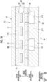
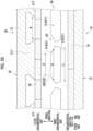
- Fig. 2A to Fig. 2D are schematic diagrams showing an internal structure of the magnetic gear 5 according to some embodiments of the present disclosure.
- the circumferential direction is shown linearly.
- Each magnetic pole piece 50 extending in the axial direction faces any one or more of the plurality of first magnets 19 with a gap G1 therebetween, and faces any one or more of the plurality of second magnets 29 with a gap G2 therebetween.
- the plurality of first magnets 19 are configured by magnets (N-pole magnets and S-pole magnets) having different magnetic poles alternately arranged in the circumferential direction.
- the plurality of second magnets 29 are configured by magnets (N-pole magnets and S-pole magnets) having different magnetic poles alternately arranged in the circumferential direction.
- a surface facing the first magnet 19 is a first opposing surface 31, and a surface facing the second magnet 29 is a second opposing surface 32.
- the magnetic pole piece 50 has a structure in which a plurality of electromagnetic steel plates 150 (see Fig. 4A ) are stacked in the axial direction. At least one of the outer circumferential surface and the inner circumferential surface of the magnetic pole piece 50 may be covered with a cover (not shown).
- the first opposing surface 31 may face the first magnet 19 with the gap G1 and the cover therebetween
- the second opposing surface 32 may face the second magnet 29 with the gap G2 and the cover therebetween.
- the magnetic pole piece unit 30 includes a holder (not shown) for holding the plurality of magnetic pole pieces 50.
- the holder made of a nonmagnetic material may be a single ring-shaped member, or may include a plurality of bar-shaped members arranged alternately with the plurality of magnetic pole pieces 50 in the circumferential direction. Both axial ends of the magnetic pole piece unit 30 formed in a ring shape by the plurality of magnetic pole pieces 50 and the holders may be coupled respectively to the pair of end plates 97 described above (see Fig. 1A ), or may be fixed to the housing 96 described above (see Fig. 1B ).
- the first yoke unit 10 is disposed on one of the outer circumferential side or the inner circumferential side of the magnetic pole piece unit 30, and the second yoke unit 20 is disposed on the other side. At least one of the first yoke unit 10 or the second yoke unit 20 is provided with a tooth portion protruding toward the magnetic pole piece unit 30, and the tooth portion supports the magnet (the first magnet 19 or the second magnet 29).
- These variations on the internal structure of the magnetic gear 5 include a first internal structure, a second internal structure, a third internal structure, a fourth internal structure, a fifth internal structure, and a sixth internal structure.
- the first yoke unit 10 is disposed on the inner circumferential side of the magnetic pole piece unit 30, and the second yoke unit 20 is disposed on the outer circumferential side. Further, the first yoke unit 10 is not provided with tooth portion, and the second yoke unit 20 is provided with tooth portion.
- a more detailed structure is as follows.
- the first yoke 15 includes a first main body portion 11, which may be a core formed of a soft magnetic material.
- the first main body portion 11 shown in Fig. 2A has an outer circumferential surface 11B that supports the plurality of first magnets 19 arranged in the circumferential direction.
- the outer circumferential surface 11B is a curved surface formed over the entire circumferential length of the magnetic gear 5.
- the second yoke 25 includes a second main body portion 21, which may be a core formed of a soft magnetic material, and at least one second tooth portion 21T. In the example of Fig.
- the second main body portion 21 has an inner circumferential surface 21A facing the plurality of second magnets 29, and the second tooth portion 21T protrudes from the inner circumferential surface 21A toward the magnetic pole piece 50 and supports one or more second magnets 29.
- the second tooth portion 21T is formed of a soft magnetic material, and may be formed integrally with the second main body portion 21.
- the second tooth portion 21T may have a tip portion configured such that the circumferential length becomes longer as approaching the magnetic pole piece 50.
- the second tooth portion 21T may have the same circumferential length regardless of the radial position (see Fig. 8 ).
- the second yoke unit 20 is disposed on the inner circumferential side of the magnetic pole piece unit 30, and the first yoke unit 10 is disposed on the outer circumferential side.
- the first yoke unit 10 is not provided with tooth portion, and the second yoke unit 20 is provided with tooth portion.
- the first yoke 15 includes a first main body portion 11, which may be a core formed of a soft magnetic material.
- the first main body portion 11 shown in Fig. 2B has an inner circumferential surface 11A that supports the plurality of first magnets 19 arranged in the circumferential direction.
- the inner circumferential surface 11A is a curved surface formed over the entire circumferential length of the magnetic gear 5.
- the second yoke 25 includes a second main body portion 21, which may be a core formed of a soft magnetic material, and at least one second tooth portion 21T. In the example of Fig.
- the second main body portion 21 has an outer circumferential surface 21B facing the plurality of second magnets 29, and the second tooth portion 21T protrudes from the outer circumferential surface 21B toward the magnetic pole piece 50 and supports one or more second magnets 29. Since the shape and material of the second tooth portion 21T are the same as those of the first internal structure, detailed description thereof is omitted.
- the third internal structure shown in Fig. 2C similarly to the first internal structure, the first yoke unit 10 is disposed on the inner circumferential side of the magnetic pole piece unit 30, and the second yoke unit 20 is disposed on the outer circumferential side.
- the third internal structure is different from the first internal structure in that tooth portions are provided in both the first yoke unit 10 and the second yoke unit 20.
- the first yoke unit 10 shown in the example of Fig. 2C includes a first main body portion 11, which may be a core formed of a soft magnetic material, and at least one first tooth portion 11T.
- the first main body portion 11 has an outer circumferential surface 11B facing the plurality of first magnets 19, and the first tooth portion 11T protrudes from the outer circumferential surface 11B toward the magnetic pole piece 50 and supports the plurality of first magnets 19.
- the outer circumferential surface 11B is a curved surface formed over the entire circumferential length of the magnetic gear 5.
- the first tooth portion 11T is formed of a soft magnetic material, and may be formed integrally with the first main body portion 11. Since the second yoke unit 20 shown in the same drawing has the same configuration as the second yoke unit 20 of the first internal structure, detailed description thereof is omitted.
- the fourth internal structure shown in Fig. 2D similarly to the second internal structure, the second yoke unit 20 is disposed on the inner circumferential side of the magnetic pole piece unit 30, and the first yoke unit 10 is disposed on the outer circumferential side.
- the fourth internal structure is different from the second internal structure in that tooth portions are provided in both the first yoke unit 10 and the second yoke unit 20.
- the first yoke unit 10 shown in the example of Fig. 2D includes a first main body portion 11, which may be a core formed of a soft magnetic material, and at least one first tooth portion 11T.
- the first main body portion 11 has an inner circumferential surface 11A facing the plurality of first magnets 19, and the first tooth portion 11T protrudes from the inner circumferential surface 11A toward the magnetic pole piece 50 and supports the plurality of first magnets 19.
- the inner circumferential surface 11A is a curved surface formed over the entire circumferential length of the magnetic gear 5.
- the first tooth portion 11T is formed of a soft magnetic material, and may be formed integrally with the first main body portion 11. Since the second yoke unit 20 shown in the same drawing has the same configuration as the second yoke unit 20 of the second internal structure, detailed description thereof is omitted.
- the fifth internal structure has a structure in which the second yoke 25 in the third internal structure does not have the second tooth portion 21T.
- the sixth internal structure has a structure in which the second yoke 25 in the fourth internal structure does not have the second tooth portion 21T. That is, in the fifth internal structure and the sixth internal structure, a configuration in which the inner circumferential surface 21A or the outer circumferential surface 21B of the second main body portion 21 supports the second magnet 29 is employed. Detailed description of these internal structures is omitted.
- FIG. 3A to 6 specific examples of the magnetic pole piece 50 applied to the above-described internal structure will be described below in order as a magnetic pole piece 51 (50) according to a first example, a magnetic pole piece 52 (50) according to a second example, and a magnetic pole piece 53 (50) according to a third example.
- a magnetic pole piece 51 (50) according to a first example will be described with reference to Figs. 3A to 4C .
- the magnetic pole piece 51 is applied to an internal structure in which tooth portion are provided in only one of the first yoke unit 10 and the second yoke unit 20. That is, the internal structure to which the magnetic pole piece 51 can be applied includes a first internal structure, a second internal structure, a fifth internal structure, and a sixth internal structure.
- an embodiment in which the magnetic pole piece 51 is applied to the first internal structure will be described, and description of embodiments in which the magnetic pole piece 51 is applied to other internal structures will be omitted.
- Figs. 3A to 3D are conceptual diagrams of the magnetic pole piece 51 according to the first example.
- Each of the magnetic pole pieces 511 to 514 (51) shown in Figs. 3A to 3D has a first opposing surface 31A to 31D (31) facing the first magnet 19 and a second opposing surface 32A to 32D (32) facing the second magnet 29.
- the magnetic pole pieces 511 to 514 (51) satisfy the relationship of L1 > L2.
- L2 shown in the same drawings is shorter than the circumferential length of the first magnet 19 and longer than the circumferential length of the second magnet 29. In another example, L2 may be shorter than the circumferential length of the second magnet 29.
- the plurality of magnetic pole pieces 511 are arranged in the circumferential direction, and when at least one magnetic pole piece 511 satisfies the relationship of L1 > L2, the above advantage can be obtained.
- at least one of the plurality of magnetic pole pieces 512 may satisfy the relationship of L1 > L2.
- the first opposing surfaces 31A to 31C (31) have first ends 311A to 311C (311) that are ends on one side in the circumferential direction and second ends 312A to 312C (312) that are ends on the other side in the circumferential direction.
- the magnetic pole pieces 511 to 513 have main body portions 60A to 60C (60).
- the main body portion 60 has the same circumferential length regardless of the radial position (for example, in Fig. 3C , both ends of the main body portion 60C in the circumferential direction are indicated by a two-dot chain line U).
- the magnetic pole pieces 511 to 513 (51) have first flange portions 61A to 61C (61) protruding from the main body portion 60 to one side in the circumferential direction and second flange portions 62A to 62C (62) protruding from the main body portion 60 to the other side in the circumferential direction.
- first flange portion 61 and the second flange portion 62 have shapes symmetrical to each other in the circumferential direction.
- the first flange portion 61 and the second flange portion 62 may have shapes asymmetrical to each other in the circumferential direction.
- the first flange portions 61A to 61C (61) have first ends 311A to 311C (311) of the first opposing surface 31, and the second flange portions 62A to 62C (62) have second ends 312A to 312C (312) of the second opposing surface 32.
- the magnetic pole piece 51 (50) since the magnetic pole piece 51 (50) includes the first flange portion 61 and the second flange portion 62, the circumferential length (L1) of the first opposing surface 31 is increased. This reduces the magnetic resistance between the magnetic pole piece 51 (50) and the first yoke unit 10, and further increases the magnetic flux flowing between the first yoke unit 10 and the second yoke unit 20 through the magnetic pole piece 51 (50). Therefore, the transmission torque is further improved.
- Fig. 3A when at least one of the plurality of magnetic pole pieces 511 has the first flange portion 61A and the second flange portion 62A, the above advantage can be obtained.
- Fig. 3B at least one of the plurality of magnetic pole pieces 512 may have the first flange portion 61B and the second flange portion 62B. The same applies to the plurality of magnetic pole pieces 513 shown in Fig. 3C .
- the shape of the magnetic pole pieces 511 and 512 (51) will be described in detail with reference to Figs. 3A and 3B .
- the first flange portions 61A and 61B (61) are configured such that the length in the radial direction decreases toward the one side.
- the second flange portions 62A and 62B (62) are configured such that the length in the radial direction decreases toward the other side.
- the first flange portion 61 has first tapered surfaces 701A and 701B (701) inclined with respect to the first opposing surface 31, and the second flange portion 62 has second tapered surfaces 702A and 702B (702) inclined with respect to the first opposing surface 31.
- the first tapered surface 701 and the second tapered surface 702 may be flat surfaces as shown in Fig. 3A or curved surfaces as shown in Fig. 3B .
- both the first tapered surface 701 and the second tapered surface 702 are directly connected to the first opposing surface 31.
- the first flange portion 61 and the second flange portion 62 may be chamfered, that is, the first tapered surface 701 and the second tapered surface 702 may be connected to the first opposing surface 31 via different surfaces (see Fig. 4C ).
- the other surface may be either a flat surface or a curved surface.
- the first flange portion 61 and the second flange portion 62 are close to the adjacent magnetic pole piece 51 (50) only at the tips. That is, the first flange portion 61 and the second flange portion 62 are partially separated from the adjacent magnetic pole pieces 51. Accordingly, it is possible to prevent the magnetic flux flowing between the two adjacent magnetic pole pieces 51. That is, the leakage magnetic flux is suppressed. Therefore, a decrease in transmission torque due to leakage of magnetic flux can be suppressed.
- the shape of the magnetic pole piece 511 (51) will be described in detail with reference to Fig. 3A .
- the second opposing surface 32A (32) has a third end 323 that is an end on one side in the circumferential direction and a fourth end 324 that is an end on the other side in the circumferential direction.
- An end of the first flange portion 61A on the second opposing surface 32A side in the radial direction is an end 611
- an end of the second flange portion 62A on the second opposing surface 32 side in the radial direction is an end 621.
- the magnetic pole piece 511 has a first connection surface 71 and a second connection surface 72.
- the first connection surface 71 and the second connection surface 72 are flat surfaces extending along the radial direction.
- the first connection surface 71 connects the end 611 of the first flange portion 61A and the third end 323 of the second opposing surface 32A
- the second connection surface 72 connects the end 621 of the second flange portion 62A and the fourth end 324 of the second opposing surface 32A.
- the first connection surface 71 extending along the radial direction may be parallel to the radial direction or substantially parallel to the radial direction.
- first connection surface 71 when an acute angle formed by the first connection surface 71 with respect to the radial direction is less than or equal to 5°, it is understood that the first connection surface 71 is substantially parallel to the radial direction. The same applies to the second connection surface 72 extending along the radial direction.
- the shape of the magnetic pole piece 51 is simplified and manufacturing is easy as compared with a case where the first connection surface 71 and the second connection surface 72 have tapered shapes that approach each other toward the second opposing surface 32A side.
- L3 represents the average circumferential magnetoresistive length of the magnetic pole pieces 511 to 514 (51).
- H the length of the magnetic pole piece in the radial direction
- Lh the length of the magnetic pole piece in the circumferential direction at a position h in the radial direction in the magnetic pole piece
- L3 a magnetoresistive average length L3 of the magnetic pole piece is represented by Expression (A).
- L3 is understood to be the average length of the magnetic pole piece 50 in the circumferential direction.
- L 3 1 1 H ⁇ 0 H 1 L h dh
- At least one second tooth portion 21T of the second yoke unit 20 includes a plurality of second tooth portions 21T arranged in the circumferential direction.
- an adjacent distance (shortest distance) between two second tooth portions 21T adjacent to each other in the circumferential direction included in the plurality of second tooth portions 21T is denoted as M
- the magnetic pole pieces 511 to 514 (51) satisfy a relationship of 0.9 ⁇ min ⁇ L2, L3 ⁇ ⁇ M ⁇ 1.1 ⁇ max ⁇ L2, L3 ⁇ .
- min ⁇ L2, L3 ⁇ is a smaller value of L2 and L3
- max ⁇ L2, L3 ⁇ is a larger value of L2 and L3.
- the magnetic pole pieces 511 to 514 (51) satisfy a relationship of 0.95 ⁇ min ⁇ L2, L3 ⁇ ⁇ M ⁇ 1.05 ⁇ max ⁇ L2, L3 ⁇ . Still more preferably, the magnetic pole pieces 511 to 514 (51) satisfy a relationship of 1.0 ⁇ min ⁇ L2, L3 ⁇ ⁇ M ⁇ 1.0 ⁇ max ⁇ L2, L3 ⁇ .
- the plurality of magnetic pole pieces 511 are arranged in the circumferential direction, and when at least one of the magnetic pole pieces 511 satisfies a relationship of 0.9 ⁇ min ⁇ L2, L3 ⁇ ⁇ M ⁇ 1.1 ⁇ max ⁇ L2, L3 ⁇ (more preferably a relationship of 0.95 ⁇ min ⁇ L2, L3 ⁇ ⁇ M ⁇ 1.05 ⁇ max ⁇ L2, L3 ⁇ , and still more preferably a relationship of 1.0 ⁇ min ⁇ L2, L3 ⁇ ⁇ M ⁇ 1.0 ⁇ max ⁇ L2, L3 ⁇ ), the above advantage is obtained.
- Fig. 3A the above advantage is obtained.
- At least one of the plurality of magnetic pole pieces 512 may satisfy the relationship of 0.9 ⁇ min ⁇ L2, L3 ⁇ ⁇ M ⁇ 1.1 ⁇ max ⁇ L2, L3 ⁇ (more preferably the relationship of 0.95 ⁇ min ⁇ L2, L3 ⁇ ⁇ M ⁇ 1.05 ⁇ max ⁇ L2, L3 ⁇ , and still more preferably the relationship of 1.0 ⁇ min ⁇ L2, L3 ⁇ ⁇ M ⁇ 1.0 ⁇ max ⁇ L2, L3 ⁇ ).
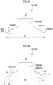
- Fig. 4A is a conceptual perspective view of a magnetic pole piece 511 (51) according to an embodiment of the present disclosure.
- Fig. 4B is a conceptual diagram of the first electromagnetic steel plate 151 according to the embodiment of the present disclosure.
- Fig. 4C is a conceptual diagram of the second electromagnetic steel plate 152 according to the embodiment of the present disclosure.
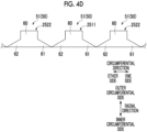
- Fig. 4D is a conceptual diagram of a magnetic pole piece 51 (50) according to an embodiment of the present disclosure. In the same drawing, the circumferential direction is shown linearly.
- the second flange portion 62 may include a second edge portion 82 that is a portion of the magnetic pole piece 511 located closest to the other side in the circumferential direction, and a second recessed portion 92 recessed from the second edge portion 82 toward the one side in the circumferential direction.
- the second edge portion 82 extends in the axial direction, and the second recessed portion 92 opens in the radial direction.
- a plurality of first recessed portions 91 may be provided in the first flange portion 61. In this case, the plurality of first recessed portions 91 are disposed at intervals in the axial direction.
- the second flange portion 62 may have a plurality of second recessed portions 92 disposed at intervals in the axial direction.
- the transmission torque increases.
- the magnetic flux of the magnetic pole piece 51 does not leak to the adjacent magnetic pole piece 51, and the magnetic flux flows in the radial direction between the first yoke unit 10 and the second yoke unit 20
- the transmission torque increases.
- the magnetic flux leaks to the adjacent magnetic pole pieces 511, and the transmission torque decreases.
- the first recessed portion 91 and the second recessed portion 92 are provided, the first flange portion 61 of the first adjacent magnetic pole piece 1511 and the second flange portion 62 of the second adjacent magnetic pole piece 1512 are partially separated from each other in the circumferential direction. Accordingly, it is possible to prevent the magnetic flux flowing between two adjacent magnetic pole pieces 511. That is, the magnetic flux leakage can be suppressed. Therefore, the transmission torque is further improved.
- the first recessed portion 91 of the first adjacent magnetic pole piece 1511 may be disposed so as to overlap at least a part of the second recessed portion 92 of the second adjacent magnetic pole piece 1512 in the axial direction, or the first recessed portion 91 may be disposed so as not to overlap the second recessed portion 92 in the axial direction at all.
- the first recessed portion 91 and the second recessed portion 92 have the same shape, and the first recessed portion 91 of the first adjacent magnetic pole piece 1511 and the second recessed portion 92 of the second adjacent magnetic pole piece 1512 are disposed so as to coincide with each other in the axial direction.
- each of the two magnetic pole pieces 511 includes a plurality of first recessed portions 91 and a plurality of second recessed portions 92, and the plurality of first recessed portions 91 and the plurality of second recessed portions 92 are arranged to coincide with each other in the axial direction.
- the configurations of the first flange portion 61 and the second flange portion 62 described above may be applied to the magnetic pole pieces 512 and 513 or may be applied to the other magnetic pole pieces 51. Even in this case, the above-described advantages are obtained.
- the magnetic pole piece 511 includes a plurality of electromagnetic steel plates 150 stacked in the axial direction.
- the magnetic pole piece 511 (51) has an axial range in which the first edge portion 81 and the second edge portion 82 are formed and an axial range in which the first recessed portion 91 and the second recessed portion 92 are formed. Therefore, the plurality of electromagnetic steel plates 150 include a first electromagnetic steel plate 151 and a second electromagnetic steel plate 152 having different shapes.
- the first electromagnetic steel plate 151 forms the first edge portion 81 and the second edge portion 82.
- both ends of the first electromagnetic steel plate 151 in the circumferential direction form the first edge portion 81 and the second edge portion 82, respectively.
- the second electromagnetic steel plate 152 forms a bottom surface of each of the first recessed portion 91 and the second recessed portion 92.
- the circumferential length (maximum circumferential length) of the second electromagnetic steel plate 152 is shorter than the circumferential length (maximum circumferential length) of the first electromagnetic steel plate 151.
- the former circumferential length corresponds to the dimension P2 in Fig. 4C
- the latter circumferential length corresponds to the dimension P1 in Fig. 4B .
- the plurality of first electromagnetic steel plates 151 are disposed on one side of the second electromagnetic steel plate 152 in the axial direction, and the plurality of first electromagnetic steel plates 151 are also disposed on the other side of the second electromagnetic steel plate 152 in the axial direction.
- the first recessed portion 91 and the second recessed portion 92 may be manufactured before the stacking process of the plurality of electromagnetic steel plates 150.
- the specified processing for forming the first recessed portion 91 and the second recessed portion 92 may be executed after the plurality of electromagnetic steel plates 150 are stacked.
- the specified machining is, for example, drilling.
- each of the first recessed portion 91 and the second recessed portion 92 is formed by the second electromagnetic steel plate 152 included in the plurality of electromagnetic steel plates 150, the configuration of the first recessed portion 91 and the second recessed portion 92 can be simplified.
- the configurations of the first flange portion 61 and the second flange portion 62 described above may be applied to the magnetic pole pieces 512 and 513 or may be applied to the other magnetic pole pieces 51. Even in this case, the above-described advantages are obtained.
- the first electromagnetic steel plate 151 has a first base portion 151A forming the main body portion 60 of the magnetic pole piece 511, a first corner portion 151B forming the first edge portion 81, and a second corner portion 151C forming the second edge portion 82.
- the first base portion 151A has the same shape as the main body portion 60 as viewed in the axial direction.
- the first corner portion 151B is a portion of the first electromagnetic steel plate 151 located closest to one side in the circumferential direction
- the second corner portion 151C is a portion of the first electromagnetic steel plate 151 located closest to the other side in the circumferential direction.
- the first corner portion 151B and the second corner portion 151C may be symmetrical to each other in the circumferential direction.
- the second electromagnetic steel plate 152 includes a second base portion 152A forming the main body portion 60 of the magnetic pole piece 511, a first protrusion portion 152B forming the bottom surface of the first recessed portion 91, and a second protrusion portion 152C forming the bottom surface of the second recessed portion 92.
- the second base portion 152A has the same shape as the first base portion 151A.
- the first protrusion portion 152B protrudes from the second base portion 152A to one side in the circumferential direction
- the second protrusion portion 152C protrudes from the second base portion 152A to the other side in the circumferential direction.
- the first protrusion portion 152B and the second protrusion portion 152C may be symmetrical to each other in the circumferential direction.
- the bottom surface of the first recessed portion 91 is formed by the tip of the first protrusion portion 152B, and the bottom surface of the second recessed portion 92 is formed by the tip of the second protrusion portion 152C.
- the plurality of magnetic pole pieces 51 (50) arranged in the circumferential direction may include a first specified magnetic pole piece 2511 and a second specified magnetic pole piece 2522 adjacent to each other in the circumferential direction.
- Each of the first specified magnetic pole piece 2511 and the second specified magnetic pole piece 2522 includes a main body portion 60, a first flange portion 61, and a second flange portion 62.
- the first flange portion 61 of the first specified magnetic pole piece 2511 and the second flange portion 62 of the second specified magnetic pole piece 2522 are in contact with each other.
- the plurality of first specified magnetic pole pieces 2511 and the plurality of second specified magnetic pole pieces 2522 are alternately arranged in the circumferential direction. Therefore, the first flange portion 61 of an arbitrary first specified magnetic pole piece 2511 is in contact with the second flange portion 62 of the second specified magnetic pole piece 2522 on one side, and the second flange portion 62 of the first specified magnetic pole piece 2511 is in contact with the first flange portion 61 of the second specified magnetic pole piece 2522 on the other side.
- the contact may be a bond, for example by welding.
- the plurality of first specified magnetic pole pieces 2511 and the plurality of second specified magnetic pole pieces 2522 arranged alternately in the circumferential direction are integrally formed with each other. According to the above configuration, the reinforcing effect of the plurality of magnetic pole pieces 51 can be improved.
- FIGS. 5A to 5D are conceptual diagrams of a magnetic pole piece 52 according to a second example.
- Fig. 5D is a conceptual diagram of the plurality of magnetic pole pieces 52 (50), and the circumferential direction is shown linearly in the same drawing.
- the magnetic pole piece 52 according to the second example is applied to an internal structure in which tooth portion are provided in at least the second yoke unit 20 of the first yoke unit 10 or the second yoke unit 20. That is, the internal structure applicable to the magnetic pole piece 52 includes a first internal structure, a second internal structure, a third internal structure, and a fourth internal structure.
- the magnetic pole piece 52 is applied to the third internal structure will be described, and description of embodiments in which the magnetic pole piece 52 is applied to other internal structures will be omitted.
- Each of the magnetic pole pieces 521 to 523 (52) shown in Figs. 5A to Fig. 5C has a first opposing surface 310A to 310C (31) facing the first magnet 19 and a second opposing surface 320A to 320C (32) facing the second magnet 29.
- the second opposing surfaces 320A to 320C have third ends 1323A to 1323C (323), which are ends on one side in the circumferential direction, and fourth ends 1324A to 1324C (324), which are ends on the other side in the circumferential direction.
- the magnetic pole pieces 521 to 523 (52) satisfy a relationship of 0.9 ⁇ min ⁇ L2, L3 ⁇ ⁇ N ⁇ 1.1 ⁇ max ⁇ L2, L3 ⁇ , where L2 is a circumferential length of the second opposing surface 32, L3 is an average length of the magnetic pole pieces 52 in the circumferential direction, and N is a circumferential length of each of the second magnets 29. More preferably, the magnetic pole pieces 521 to 523 (52) satisfy a relationship of 0.95 ⁇ min ⁇ L2, L3 ⁇ ⁇ N ⁇ 1.05 ⁇ max ⁇ L2, L3 ⁇ . Still more preferably, the magnetic pole pieces 521 to 523 (52) satisfy a relationship of 1.0 ⁇ min ⁇ L2, L3 ⁇ ⁇ N ⁇ 1.0 ⁇ max ⁇ L2, L3 ⁇ .
- the magnetic pole pieces 521 to 523 (52) have main body portions 160A to 160C (60), third flange portions 63A to 63C (63) that protrudes from the main body portion 60 to one side in the circumferential direction, and fourth flange portions 64A to 64C (64) protruding from the main body portion 60 to the other side in the circumferential direction.
- the shape of the main body portion 60 of the magnetic pole piece 52 is the same as the shape of the main body portion 60 according to the first example.
- the first flange portion 61 and the second flange portion 62 have shapes symmetrical to each other in the circumferential direction, but may be asymmetrical.
- the third flange portions 63A to 63C have third ends 1323A to 1323C of the second opposing surface 32
- the fourth flange portions 64A to 64C have fourth ends 1324A to 1324C of the second opposing surface 32.
- the magnetic pole piece 52 satisfying the relationship of 0.9 ⁇ min ⁇ L2, L3 ⁇ ⁇ N ⁇ 1.1 ⁇ max ⁇ L2, L3 ⁇ (more preferably the relationship of 0.95 ⁇ min ⁇ L2, L3 ⁇ ⁇ N ⁇ 1.05 ⁇ max ⁇ L2, L3 ⁇ , and still more preferably the relationship of 1.0 ⁇ min ⁇ L2, L3 ⁇ ⁇ N ⁇ 1.0 ⁇ max ⁇ L2, L3 ⁇ ) can obtain a continuous magnetic reluctance torque in the process in which the positional relationship between the magnetic pole piece 52 and the second yoke 25 relatively changes in the circumferential direction in accordance with the operation of the magnetic gear 5 (the reason will be described in detail in " ⁇ 6.
- the magnetic pole piece 52 since the magnetic pole piece 52 has the third flange portion 63 and the fourth flange portion 64, it is possible to partially short-circuit the magnetomotive force that switches between positive and negative, and it is possible to moderate the switching between positive and negative of the magnetomotive force.
- the magnetic gear 5 can continue to rotate smoothly.
- the plurality of magnetic pole pieces 521 are arranged in the circumferential direction, and when at least one of the magnetic pole pieces 521 satisfies a relationship of 0.9 ⁇ min ⁇ L2, L3 ⁇ ⁇ N ⁇ 1.1 ⁇ max ⁇ L2, L3 ⁇ (more preferably a relationship of 0.95 ⁇ min ⁇ L2, L3 ⁇ ⁇ N ⁇ 1.05 ⁇ max ⁇ L2, L3 ⁇ , and still more preferably a relationship of 1.0 ⁇ min ⁇ L2, L3 ⁇ ⁇ N ⁇ 1.0 ⁇ max ⁇ L2, L3 ⁇ ), the above advantage is obtained.
- Fig. 5A the above advantage is obtained.
- At least one of the plurality of magnetic pole pieces 522 may satisfy the relationship of 0.9 ⁇ min ⁇ L2, L3 ⁇ ⁇ N ⁇ 1.1 ⁇ max ⁇ L2, L3 ⁇ (more preferably the relationship of 0.95 ⁇ min ⁇ L2, L3 ⁇ ⁇ N ⁇ 1.05 ⁇ max ⁇ L2, L3 ⁇ , and still more preferably the relationship of 1.0 ⁇ min ⁇ L2, L3 ⁇ ⁇ N ⁇ 1.0 ⁇ max ⁇ L2, L3 ⁇ ).
- the shape of the magnetic pole pieces 521 and 522 (52) will be described in detail with reference to Fig. 5A and Fig. 5B .
- the third flange portions 63A and 63B (63) are configured such that the length in the radial direction decreases toward the one side.
- the fourth flange portions 64A and 64B (64) are configured such that the length in the radial direction decreases toward the other side.
- the third flange portion 63 has third tapered surfaces 703A and 703B (703) inclined with respect to the second opposing surface 32
- the second flange portion 62 has fourth tapered surfaces 704A and 704B (704) inclined with respect to the second opposing surface 32.
- the third tapered surface 703 and the fourth tapered surface 704 may be flat surfaces as shown in Fig. 5A or curved surfaces as shown in Fig. 5B .
- both the third tapered surface 703 and the fourth tapered surface 704 are directly connected to the second opposing surface 32.
- the third flange portion 63 and the fourth flange portion 64 may be chamfered, that is, the third tapered surface 703 and the fourth tapered surface 704 may be connected to the second opposing surface 32 via different surfaces.
- the other surface may be either a flat surface or a curved surface.
- the second opposing surface 32 of the magnetic pole piece 52 can cover the second magnet 29 without excess or deficiency in the circumferential direction, and the magnetic flux flowing between the first yoke unit 10 and the second yoke unit 20 in the radial direction due to the magnetomotive force of the second magnet 29 is maximized, so that the transmission torque is further improved.
- the second opposing surface 32 of the magnetic pole piece 50 is excessive with respect to the circumferential length (N) of the second magnet 29, and the excessive portion of the second opposing surface 32 of the magnetic pole piece 50 receives the magnetomotive force in the opposite direction from the adjacent second magnet 29. Therefore, the magnetomotive force received by the second opposing surface 32 of the magnetic pole piece 50 as a whole is weakened. Thus, it is effective that the second opposing surface 32 of the magnetic pole piece 50 covers the second magnet 29 in the circumferential direction without excess or deficiency.
- Fig. 5A when at least one of the plurality of magnetic pole pieces 521 has the third flange portion 63A and the fourth flange portion 64A, the above advantage can be obtained.
- Fig. 5B at least one of the plurality of magnetic pole pieces 522 may have the third flange portion 63B and the fourth flange portion 64B.
- the shape of the magnetic pole piece 521 (52) will be described in detail with reference to Fig. 5A .
- the first opposing surface 310A has a first end 1311 (311) that is an end on one side in the circumferential direction and a second end 1312 (312) that is an end on the other side in the circumferential direction.
- An end of the third flange portion 63A on the first opposing surface 31 side in the radial direction is an end 1611
- an end of the fourth flange portion 64A on the first opposing surface 31 side in the radial direction is an end 1621.
- the magnetic pole piece 521 (52) has a third connection surface 73 and a fourth connection surface 74.
- the third connection surface 73 and the fourth connection surface 74 are flat surfaces extending along the radial direction.
- the third connection surface 73 connects the end 1611 of the third flange portion 63 and the third end 1323A of the second opposing surface 32
- the fourth connection surface 74 connects the end 1621 of the fourth flange portion 64 and the fourth end 1324A of the second opposing surface 32.
- the third connection surface 73 extending along the radial direction may be parallel to the radial direction or substantially parallel to the radial direction.
- the third connection surface 73 is substantially parallel to the radial direction.
- the fourth connection surface 74 extending along the radial direction. According to the above configuration, since the third connection surface 73 and the fourth connection surface 74 extend along the radial direction, the shape of the magnetic pole piece 52 (50) is simplified, and manufacturing can be facilitated.
- At least one second tooth portion 21T of the second yoke unit 20 includes a plurality of second tooth portions 21T arranged in the circumferential direction.
- an adjacent distance (shortest distance) between two second tooth portions 21T adjacent to each other in the circumferential direction included in the plurality of second tooth portions 21T is denoted as M as in the first example
- the magnetic pole pieces 521 to 523 (52) satisfy a relationship of 0.9 ⁇ min ⁇ L2, L3 ⁇ ⁇ M ⁇ 1.1 ⁇ max ⁇ L2, L3 ⁇ .
- the magnetic pole pieces 521 to 523 (52) satisfy a relationship of 0.95 ⁇ min ⁇ L2, L3 ⁇ ⁇ M ⁇ 1.05 ⁇ max ⁇ L2, L3 ⁇ . Still more preferably, the magnetic pole pieces 521 to 523 (52) satisfy a relationship of 1.0 ⁇ min ⁇ L2, L3 ⁇ ⁇ M ⁇ 1.0 ⁇ max ⁇ L2, L3 ⁇ .
- the magnetic flux leaks from one second tooth portion 21T to another second tooth portion 21T via the magnetic pole piece 52 (50), and the magnetic flux flowing in the radial direction decreases.
- the plurality of magnetic pole pieces 521 are arranged in the circumferential direction, and when at least one of the magnetic pole pieces 521 satisfies a relationship of 0.9 ⁇ min ⁇ L2, L3 ⁇ ⁇ M ⁇ 1.1 ⁇ max ⁇ L2, L3 ⁇ (more preferably a relationship of 0.95 ⁇ min ⁇ L2, L3 ⁇ ⁇ M ⁇ 1.05 ⁇ max ⁇ L2, L3 ⁇ , and still more preferably a relationship of 1.0 ⁇ min ⁇ L2, L3 ⁇ ⁇ M ⁇ 1.0 ⁇ max ⁇ L2, L3 ⁇ ), the above advantage is obtained.
- Fig. 5A the above advantage is obtained.
- At least one of the plurality of magnetic pole pieces 522 may satisfy the relationship of 0.9 ⁇ min ⁇ L2, L3 ⁇ ⁇ M ⁇ 1.1 ⁇ max ⁇ L2, L3 ⁇ (more preferably the relationship of 0.95 ⁇ min ⁇ L2, L3 ⁇ ⁇ M ⁇ 1.05 ⁇ max ⁇ L2, L3 ⁇ , and still more preferably the relationship of 1.0 ⁇ min ⁇ L2, L3 ⁇ ⁇ M ⁇ 1.0 ⁇ max ⁇ L2, L3 ⁇ ).
- the plurality of magnetic pole pieces 52 (50) arranged in the circumferential direction may include a first specified magnetic pole piece 3511 and a second specified magnetic pole piece 3522 adjacent to each other in the circumferential direction.
- Each of the first specified magnetic pole piece 3511 and the second specified magnetic pole piece 3522 includes a main body portion 60, a third flange portion 63, and a fourth flange portion 64.
- the third flange portion 63 of the first specified magnetic pole piece 3511 and the fourth flange portion 64 of the second specified magnetic pole piece 3522 are in contact with each other.
- the plurality of first specified magnetic pole pieces 3511 and the plurality of second specified magnetic pole pieces 3522 are alternately arranged in the circumferential direction. Therefore, the third flange portion 63 of an arbitrary first specified magnetic pole piece 3511 is in contact with the fourth flange portion 64 of the second specified magnetic pole piece 3522 on one side, and the fourth flange portion 64 of the first specified magnetic pole piece 3511 is in contact with the third flange portion 63 of the second specified magnetic pole piece 3522 on the other side.
- the contact may be a bond, for example by welding.
- the plurality of first specified magnetic pole pieces 3511 and the plurality of second specified magnetic pole pieces 3522 arranged alternately in the circumferential direction are integrally formed with each other. According to the above configuration, the reinforcing effect of the plurality of magnetic pole pieces 52 (50) can be improved.
- Fig. 6 is a conceptual diagram of a magnetic pole piece 53 (50) according to a third example.
- the magnetic pole piece 53 is applied to an internal structure in which a tooth portion is provided in at least the second yoke unit 20 of the first yoke unit 10 or the second yoke unit 20. That is, the internal structure applicable to the magnetic pole piece 53 includes a first internal structure, a second internal structure, a third internal structure, and a fourth internal structure.
- an embodiment in which the magnetic pole piece 53 is applied to the third internal structure will be described, and description of embodiments in which the magnetic pole piece 53 is applied to other internal structures will be omitted.
- the magnetic pole piece 53 (50) includes the first opposing surface 31 facing the first magnet 19 and the second opposing surface 32 facing the second magnet 29.
- At least one second tooth portion 21T of the second yoke 25 includes a plurality of second tooth portions 21T arranged in the circumferential direction.
- the first yoke 15 includes a plurality of first tooth portions 11T arranged in the circumferential direction.
- the circumferential length of the second opposing surface 32 is L2
- the average length of the magnetic pole pieces 53 in the circumferential direction is L3
- the adjacent distance between two adjacent second tooth portions 21T included in the plurality of second tooth portions 21T is M
- at least one of the plurality of magnetic pole pieces 53 satisfies a relationship of 0.9 ⁇ min ⁇ L2, L3 ⁇ ⁇ M ⁇ 1.1 ⁇ max ⁇ L2, L3 ⁇ (more preferably a relationship of 0.95 ⁇ min ⁇ L2, L3 ⁇ ⁇ M ⁇ 1.05 ⁇ max ⁇ L2, L3 ⁇ , and still more preferably a relationship of 1.0 ⁇ min ⁇ L2, L3 ⁇ ⁇ M ⁇ 1.0 ⁇ max ⁇ L2, L3 ⁇ ).
- the shape of the magnetic pole piece 53 (50) shown in Fig. 6 is merely an example.
- the magnetic flux flowing in the radial direction decreases.
- the magnetic gear 5 having the tooth portion that protrudes toward the magnetic pole piece 53 and supports the magnet and having improved transmission torque is realized.
- the internal structure applicable to the magnetic pole pieces 52 and 53 (50) includes the third internal structure and the fourth internal structure. Additional configurations in these internal structures will be described with reference to Figs. 7A and 7B showing a third internal structure. In order to avoid redundant description, the same description of the fourth internal structure is omitted.
- Fig. 7A is a schematic diagram showing a third internal structure according to an embodiment
- Fig. 7B is a schematic diagram showing a third internal structure according to another embodiment.
- at least one first tooth portion 11T includes a plurality of first tooth portions 11T arranged in the circumferential direction
- at least one second tooth portion 21T includes a plurality of second tooth portions 21T arranged in the circumferential direction.
- the ratio of the number (p1) of the plurality of first magnets 19 to the number (h1) of the plurality of first tooth portions 11T is equal to the ratio of the number (p2) of the plurality of second magnets 29 to the number (h2) of the plurality of second tooth portions 21T. That is, the following Formula (B) is established.
- p 1 : h 1 p 2 : h 2
- p1 is the number of poles of the plurality of first magnets 19
- p2 is the number of poles of the plurality of second magnets 29.
- the plurality of first magnets 19 are configured by N-pole magnets and S-pole magnets alternately arranged in the circumferential direction, and the plurality of second magnets 29 also have the same configuration.
- Expression (B) since Expression (B) is satisfied, when the magnetic gear 5 operates, the cycle in which the first magnet 19 facing the magnetic pole piece 52 (50) is switched from one of the N-pole magnet and the S-pole magnet to the other coincides with the cycle in which the second magnet 29 facing the magnetic pole piece 52 (50) is switched from one of the N-pole magnet and the S-pole magnet to the other.
- the same two cycles may be referred to as a prescribed cycle.
- the plurality of first magnets 19 shown in Fig. 7A include first specified magnets 191.
- the center of the first specified magnet 191 coincides with the center of the first tooth portion 11T supporting the first specified magnet 191.
- Both centers shown in Fig. 7A are on a two-dot chain line C1 parallel to the radial direction.
- the center of the first tooth portion 11T and the center of the first magnet 19 do not coincide with each other in the circumferential direction.
- the above-described first specified magnet 191 may be disposed in each of the plurality of first tooth portions 11T.
- the plurality of second magnets 29 include second adjacent magnets 295 adjacent to each other in the circumferential direction.
- any one of the intermediate points of the two second adjacent magnets 295 coincides with the center of the single second tooth portion 21T supporting the two second adjacent magnets 295.
- the intermediate point and the center are on a two-dot chain line C2 parallel to the radial direction in the example of Fig. 7A .
- the center of the second tooth portion 21T does not coincide with the intermediate point between the two adjacent second magnets 29 in the circumferential direction.
- two second adjacent magnets 295 may be disposed in each of the plurality of second tooth portions 21T.
- the shortest distance in the circumferential direction between the intermediate point between the two second adjacent magnets 295 and the center of the single second tooth portion 21T is less than 10% of the circumferential length of the second magnet 29, it is understood that the intermediate point and the center coincide with each other.
- the timing at which the first magnet 19 facing the magnetic pole piece 50 is switched from one of the N-pole magnet and the S-pole magnet to the other and the timing at which the second magnet 29 facing the magnetic pole piece 50 is switched from one of the N-pole magnet and the S-pole magnet to the other are shifted from each other by half of the above-described specified period, that is, 180 degrees in the specified period.
- the timing at which the second magnet 29 is switched from one of the N-pole magnet and the S-pole magnet to the other in the second tooth portion 21T and the timing at which the first magnet 19 is switched from one of the N-pole magnet and the S-pole magnet to the other in the first tooth portion 11T are generated at equal intervals shifted by 180 degrees in the specified cycle, and the generated torque is temporally equalized.
- the magnetomotive force exerted by the first magnet 19 on the magnetic pole piece 50 is maximized, but the N magnetic pole and the S magnetic pole cancel each other out in the second magnet 29, and the magnetomotive force from the second magnet does not act on the magnetic pole piece 50. Accordingly, it is possible to prevent the transmission torque of the magnetic gear 5 from decreasing due to the magnetic flux saturation.
- two first adjacent magnets 195 may be disposed in each of the plurality of first tooth portions 11T.
- the shortest distance in the circumferential direction between the intermediate point between the two first adjacent magnets 195 and the center of the single first tooth portion 11T is less than 10% of the circumferential length of the first magnet 19, it is understood that the intermediate point and the center coincide with each other.
- the plurality of second magnets 29 include a second specified magnet 291.
- the center of the second specified magnet 291 coincides with the center of the single second tooth portion 21T supporting the second specified magnet 291.
- Both centers shown in Fig. 7B are on a two-dot chain line C4 parallel to the radial direction.
- the center of the second tooth portion 21T and the center of the second magnet 29 do not coincide with each other in the circumferential direction.
- the second specified magnet 291 described above may be disposed in each of the plurality of second tooth portions 21T. When the shortest distance in the circumferential direction between the center of the second specified magnet 291 and the center of the second tooth portion 21T is less than 10% of the circumferential length of the second specified magnet 291, it is understood that both centers coincide with each other.
- the timing at which the first magnet 19 facing the magnetic pole piece 50 is switched from one of the N-pole magnet and the S-pole magnet to the other and the timing at which the second magnet 29 facing the magnetic pole piece 50 is switched from one of the N-pole magnet and the S-pole magnet to the other are shifted from each other by a half of the above-described specified period. Accordingly, the magnetic gear 5 can improve the transmission torque.
- a distance from a rotation center (hereinafter, also simply referred to as an axial center) of the magnetic gear 5 to the outer circumferential surface 11B of the first main body portion 11 (one end surface of the first magnet 19) is R1.
- a distance from the axial center to one end surface of the second magnet 29 facing the magnetic pole piece 50 is defined as R2.
- a distance from the axial center to the other end surface of the second magnet 29 (the tip of the second tooth portion 21T) is defined as R3.
- the radial lengths of the first magnet 19, the magnetic pole piece 50, and the second magnet 29 are t 1 , t 2 , and t 3 , respectively.
- the radial lengths of the gap G1 (see Fig. 2A ) and the gap G2 (see Fig. 2A ) are t 12 and t 23 , respectively.
- a magnetic flux between the magnetic pole piece 50 and the second tooth portion 21T is considered.
- the position of the magnetic gear 5 in the circumferential direction is represented by ⁇ .
- the magnetic pole piece 50 and the second tooth portion 21T are arranged in the radial direction in a section where ⁇ LT ⁇ ⁇ ⁇ ⁇ RT .
- a rectangle indicated by a two-dot chain line J1 in the same drawing is a region in which the magnetic pole piece 50 and the second tooth portion 21T are arranged.
- the magnetomotive force F T acting on the second tooth portion 21T and the magnetic pole piece 50 can be approximated by the following equation (3), where M 3 ⁇ is the magnetic moment of the second magnet 29 at the position ⁇ .
- M 3 ⁇ is +M or -M depending on ⁇ .
- F T t 3 ⁇ RT ⁇ ⁇ LT ⁇ ⁇ LT ⁇ RT M 3 ⁇ d ⁇
- the magnetic flux ⁇ T between the second tooth portion 21T and the magnetic pole piece 50 is represented by the following equation (4).
- the direction of the magnetic flux ⁇ T between the second tooth portion 21T and the magnetic pole piece 50 is defined such that the direction from the magnetic pole piece 50 to the second tooth portion 21T is positive.
- ⁇ T g T F T ⁇ F 2
- the magnetic flux between the magnetic pole piece 50 and the first yoke 15 will be considered.
- the first yoke 15 is not provided with a tooth portion, and the magnetic pole pieces 50 are arranged in the radial direction as a whole with respect to the first yoke 15.
- a region surrounded by a rectangle indicated by a two-dot chain line J2 in the same drawing corresponds to this.
- the permeance g B of the magnetic pole piece 50 and the first yoke 15 is represented by the following equation (5), where L is the axial length of the first tooth portion 11T.
- g B ⁇ LR 2 ⁇ RB ⁇ ⁇ LB t 1 + t 23
- the magnetomotive force F B acting on the magnetic pole piece 50 and the first yoke 15 is represented by the following equation (6), where M 1 ⁇ is the magnetic moment of the magnetic pole of the first yoke 15 at the position ⁇ .
- M 1 ⁇ is +M or -M depending on ⁇ .
- F B t 1 ⁇ RB ⁇ ⁇ LB ⁇ ⁇ LB ⁇ RB M 1 ⁇ d ⁇
- a magnetic flux ⁇ B between the magnetic pole piece 50 and the first yoke 15 is represented by the following equation (7).
- the direction of the magnetic flux ⁇ T between the first yoke 15 and the magnetic pole piece 50 is positive in the direction from the first yoke 15 to the magnetic pole piece 50.
- ⁇ B g B F B ⁇ F 2
- Expression (8) can be represented by Expression (8A).
- ⁇ g TB F T ⁇ F B
- the torque generated in the first yoke 15 and the magnetic pole piece 50 is obtained by partially differentiating the energy of the magnetic flux between the first yoke 15 and the second yoke 25 at each position.
- the torque T 1 generated in the first yoke 15 by the magnetic flux ⁇ L passing through the magnetic pole piece 50 is represented by the following equation (11), where ⁇ 1 is the position of the first yoke 15.
- T 1 1 2 ⁇ g TB ⁇ ⁇ 1 F T + F B 2 + g TB F T + F B ⁇ F T ⁇ ⁇ 1 + ⁇ F B ⁇ ⁇ 1
- T 2 1 2 ⁇ g TB ⁇ ⁇ 2 F T + F B 2 + g TB F T + F B ⁇ F T ⁇ ⁇ 2 + ⁇ F B ⁇ ⁇ 2
- the torque T 2 is the sum of a term proportional to the gradient ⁇ g TB / ⁇ 2 of the permeance in the first term on the right side and a term proportional to the gradient ⁇ F TB / ⁇ 2 + ⁇ F B / ⁇ 2 of the magnetomotive force in the second term on the right side, as shown in Expression (12).
- the term proportional to the gradient of the permeance is the force with which the magnet attracts the magnetic pole piece 50, and is the magnetic reluctance torque.
- the term proportional to the gradient of the magnetomotive force is a repulsive force and an attractive force acting on the magnets and is a magnet torque.
- Equation (13) is simplified using the fact that only the permeance g T between the first tooth portion 11T and the magnetic pole piece 50 is affected by the first yoke 15, and the permeance g B between the first yoke 15 and the magnetic pole piece 50 is irrelevant to the magnetic pole piece 50.
- Equation (13) it can be seen from Equation (13) that, by increasing g B , the value of the first term of Equation (12) increases, and the torque generated in the magnetic pole piece unit 30 also increases.
- the circumferential length of the first opposing surface 31 may be increased. That is, it is understood that the transmission torque is improved by setting L1 > L2.
- L1 may be increased to such an extent that two adjacent magnetic pole pieces 50 are in contact with each other.
- the same conclusion can be obtained when the magnetic pole piece unit 30 is a stator and the first yoke unit 10 and the second yoke unit 20 are rotors. The same conclusion can be obtained even when the second internal structure, the fifth internal structure, and the sixth internal structure are employed.
- Fig. 9 is a conceptual graph showing various parameters corresponding to the circumferential positions of the plurality of magnetic pole pieces 50 having different circumferential lengths.
- the magnetomotive force F T acting on the magnetic pole piece 50 and the second tooth portion 21T is represented by the equation (3).
- (A) of the same drawing shows the magnetic moment M 3 ⁇ of the second magnet 29 according to the circumferential position.
- the second magnets 29 that is, the N-pole magnets and the S-pole magnets
- the second magnets 29 are arranged in the circumferential direction so that the polarities of the magnetic moments of the second magnets 29 are reversed in the order of -M, +M, and ....
- the magnetomotive force F T acting on the magnetic pole piece 50 is proportional to an average value of magnetic moments of portions of the magnetic pole piece 50 arranged with the second tooth portion 21T in the radial direction.
- (B) shows the magnetomotive force (F T ) 1/2 when the circumferential length of the magnetic pole piece 50 is half the circumferential length of the second magnet 29
- (C) shows the magnetomotive force (F T ) 2/2 when the circumferential length of the magnetic pole piece 50 is equal to the circumferential length of the second magnet 29
- (D) shows the magnetomotive force (F T ) 3/2 when the circumferential length of the magnetic pole piece 50 is 1.5 times the circumferential length of the second magnet 29.
- a case where the circumferential length of the magnetic pole piece 50 is half the circumferential length of the magnetic pole of the second tooth portion 21T is referred to as a first case
- a case where the circumferential length of the magnetic pole piece 50 is equal to the circumferential length of the magnetic pole of the second tooth portion 21T is referred to as a second case
- a case where the circumferential length of the magnetic pole piece 50 is 1.5 times the circumferential length of the magnetic pole of the second tooth portion 21T is referred to as a third case.
- (E) of the same drawing shows g T F T according to ⁇ 2
- (F) of the same drawing shows g T F T ⁇ ⁇ F 1 / ⁇ 2 according to ⁇ 2 .
- ⁇ 2 is the circumferential position of the circumferential center of the magnetic pole piece 50.
- the gradient ⁇ F 1 / ⁇ 2 of the magnetomotive force of (F T ) 1/2 in the first case is the largest among the three, but there is a section in which the gradient is zero.
- the torque (g T F T ⁇ ⁇ F T / ⁇ 2 ) 1/2 in the first case is disadvantageous in that the torque due to the gradient of the magnetomotive force becomes zero in the section where the gradient is zero, and the torque becomes intermittent.
- the torque (g T F T ⁇ ⁇ F T / ⁇ 2 ) 2/2 can be obtained without interruption. This is advantageous in reducing vibration. This advantage is obtained when the circumferential length (L2) of the magnetic pole piece 50 is equal to or longer than the circumferential length (N) of the second magnet 29.
- the magnetic pole piece 50 faces the two second magnets 29 (the N-pole magnet and the S-pole magnet) on both the positive and negative sides, cancellation of the magnetic moments occurs. Therefore, as shown in (D) of the same drawing, the peak of the magnetomotive force (F T ) 3/2 in the third case is smaller than those in the other two cases.
- the torque is proportional to the gradient of the magnetomotive force ⁇ (magnetomotive force ⁇ permeance).
- the second case in which a continuously large torque is obtained is the best.
- it is an ideal state that the circumferential length L2 of the magnetic pole piece 50 is equal to N.
- the ideal state is approximately achieved.
- it can be regarded as an approximate ideal state (naturally, the difference between them is preferably as small as possible, for example, when the difference between them is within 5%, the approximate ideal state is more preferably achieved, and when the error can be regarded as 0%, the ideal state is still more preferably achieved).
- the circumferential length L2 of the magnetic pole piece 50 is a numerical value of the second opposing surface 32 of the magnetic pole piece 50 facing the second magnet 29 (that is, a numerical value of a local portion of the magnetic pole piece 50).
- the circumferential length L2 of the second opposing surface 32A can be extended as in the magnetic pole piece 512 (see Fig. 3A ) given as an example of the magnetic pole piece 50, or the circumferential length L2 of the second opposing surface 32D can be shortened as in the magnetic pole piece 514 (see Fig. 3D ) given as an example of the magnetic pole piece 50.
- the relationship between only two parameters L2 and N does not necessarily represent the essence of the technique of the present disclosure (that is, the magnitude of the transmission torque is not necessarily determined by only these two parameters). Therefore, the inventor claims that when the magnetic pole piece 50 satisfying the relationship of 0.9 ⁇ min ⁇ L2, L3 ⁇ ⁇ N ⁇ 1.1 ⁇ max ⁇ L2, L3 ⁇ is adopted by supplementarily using L3 as the magnetoresistive average circumferential length of the magnetic pole piece 50 defined by the formula (A) as the representative value of the circumferential length of the magnetic pole piece 50, further improvement of the transmission torque is expected.
- 0.9 and 1.1 in the inequality correspond to the lower limit value and the upper limit value of the difference of 10% from the ideal state described above, respectively.
- the magnetic pole piece 50 in order to more preferably achieve the approximate ideal state, it is preferable to adopt the magnetic pole piece 50 satisfying the relationship of 0.95 ⁇ min ⁇ L2, L3 ⁇ ⁇ N ⁇ 1.05 ⁇ max ⁇ L2, L3 ⁇ . In order to more preferably achieve the approximate ideal state, it is preferable to adopt the magnetic pole piece 50 satisfying the relationship of 1.0 ⁇ min ⁇ L2, L3 ⁇ ⁇ N ⁇ 1.0 ⁇ max ⁇ L2, L3 ⁇ .
- the embodiment in which the magnetic pole piece 50 is a rotor has been described, but the same result can be obtained even in an embodiment in which the magnetic pole piece 50 is a stator. This is because the transmission torque is generated by a relative change in the circumferential positional relationship among the first yoke unit 10, the second yoke unit 20, and the magnetic pole piece unit 30.
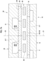
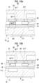
- FIGs. 10A and 10B are schematic diagrams showing a third internal structure according to an embodiment.
- the torque T 1 exerted on the first yoke 15 by one magnetic pole piece 50 and the torque T 2 exerted on the second yoke 25 by the magnetic pole piece 50 are represented by the equations (11) and (12) as described above.
- the second tooth portion 21T has a strong influence on the magnetic reluctance torque of the first term on the right side of Expression (11) and Expression (12).
- g TB is the permeance between the first yoke 15 and the second yoke 25, and is represented by Equation (9) as described above.
- g B is the permeance of the first yoke 15 and the magnetic pole piece 50.
- Fig. 10A shows a state in which the entire magnetic pole piece 50 is arranged with the first tooth portion 11T of the first yoke 15 in the radial direction.
- Fig. 10B shows a state in which the magnetic pole piece 50 is shifted in the circumferential direction with respect to the first tooth portion 11T.
- the magnetic pole piece 50 and the second tooth portion 21T are arranged in the radial direction in a region indicated by a two-dot chain line Q1 in Fig. 10A , and the permeance of the magnetic pole piece 50 and the second tooth portion 21T in the region is denoted by g T .
- the magnetic pole piece 50 is arranged with the first tooth portion 11T in the radial direction in a region indicated by a two-dot chain line Q2 in Fig. 10A , and the permeance of the magnetic pole piece 50 and the first tooth portion 11T in the region is denoted by g B .
- the gradient of the permeance is represented by the following equation (15).
- Expression (15) indicates that the magnetic reluctance torque is obtained in proportion to the area of the surface of the one end surface of the second magnet 29 facing the magnetic pole piece 50 (that is, the area can be approximated to the area of the surface of the second opposing surface 32 of the magnetic pole piece 50 facing the second magnet 29).
- both the magnetic reluctance torque of the first term of the right side of the equation (12) and the magnet torque of the second term act on the second yoke 25. This situation is preferable because the transmission torque is improved.
- 11D are magnetic geared motors 3A, 3B (3) configured to receive a supply of power P from a power supply source 6, which may be, for example, a power grid, to drive a rotary machine 8.
- the rotary machine 8 may be, for example, an electric vehicle that travels by driving of the magnetic geared motor 3.
- the magnetic geared motor 3 may be coupled to a drive shaft of the electric vehicle, which is a component of the rotary machine 8.
- the magnetic geared electrical machines 1A and 1C shown in Fig. 11A and Fig. 11C incorporate a magnetic gear 5A (see Fig. 1A ), and the magnetic geared electrical machines 1B and 1D shown in Fig. 11B and Fig. 11D incorporate a magnetic gear 5B (see Fig. 1B ).
- the magnetic geared generator 2A, 2B (2) includes the magnetic gear 5 and the coil 99 wound around the second tooth portion 21T or the magnetic pole piece 50.
- the coil 99 is provided so as to be electrically conducted to the power supply destination 4.
- the coil 99 functioning as a stator winding (armature winding) is provided on the plurality of second tooth portions 21T in Fig. 11A , and is provided on the plurality of magnetic pole pieces 50 in Fig. 11B .
- the magnetic geared motor 3A, 3B (3) includes the magnetic gear 5 and the coil 99 wound around the second tooth portion 21T or the magnetic pole piece 50.
- the coil 99 is provided so as to be electrically conducted to the power supply source 6.
- the coil 99 functioning as a stator winding (armature winding) is provided on the plurality of second tooth portions 21T in Fig. 11C , and is provided on the plurality of magnetic pole pieces 50 in Fig. 11D .
- the operating principle of the magnetic geared motor 3B shown in Fig. 11D is similar to that of the magnetic geared motor 3A.
- the second yoke unit 20 is biased by a rotating magnetic field generated by energization of the coil 99.
- the second rotation axis A2 which functions as an output shaft in the example of the same drawing, drives the rotary machine 8.
- the magnetic geared electrical machine (1) can improve the transmission torque.
- the magnetic geared generator 2 may not include the first rotation axis A1 or the second rotation axis A2 functioning as the output shaft, and the magnetic geared motor 3 may not include the first rotation axis A1 or the second rotation axis A2 functioning as the input shaft. Even in this case, the above-described advantages are obtained.
- the transmission torque is improved. Therefore, according to the above configuration 1), it is possible to realize the magnetic gear (5) having the tooth portion that protrudes toward the magnetic pole piece (50) and supports the magnet, and having improved transmission torque.
- the magnetic pole piece (50) since the magnetic pole piece (50) includes the first flange portion (61) and the second flange portion (62), the length of the first opposing surface (31) in the circumferential direction increases. This reduces the magnetic resistance between the magnetic pole piece (50) and the first yoke unit (10), and further increases the magnetic flux flowing between the first yoke unit (10) and the second yoke unit (20) through the magnetic pole piece (50). Therefore, the transmission torque is further improved.
- the first flange portion (61) and the second flange portion (62) are close to the adjacent magnetic pole piece (50) only at the tips. That is, the first flange portion (61) and the second flange portion (62) are partially separated from the adjacent magnetic pole piece (50). As a result, it is possible to prevent the flow of magnetic flux between the two adjacent magnetic pole pieces (50). That is, the leakage magnetic flux is suppressed. Therefore, a decrease in transmission torque due to leakage of magnetic flux can be suppressed.
- the transmission torque increases.
- the magnetic flux of the magnetic pole piece (50) does not leak to the adjacent magnetic pole piece (50) and is a magnetic flux that flows in the radial direction between the first yoke unit (10) and the second yoke unit (20)
- the transmission torque increases.
- the distance between two adjacent magnetic pole pieces (50) is too short, the magnetic flux flows between the two magnetic pole pieces (50), and the transmission torque decreases.
- the first recessed portion (91) and the second recessed portion (92) are provided, the first flange portion (61) and the second flange portion (62) are partially separated from the adjacent magnetic pole piece (50) in the circumferential direction.
- the magnetic flux flowing between the two adjacent magnetic pole pieces (50) can be suppressed. That is, the leakage magnetic flux can be suppressed. Therefore, the transmission torque is further improved.
- a magnetic gear (5) according to at least one embodiment of the present disclosure includes,
- the magnetic pole piece (50) satisfying the relationship of 0.9 ⁇ min ⁇ L2, L3 ⁇ ⁇ N ⁇ 1.1 ⁇ max ⁇ L2, L3 ⁇ can obtain a continuous magnetic reluctance torque in the process in which the positional relationship between the magnetic pole piece (50) and the second yoke (25) relatively changes in the circumferential direction as the magnetic gear (5) operates.
- the magnetic gear (5) that includes the tooth portion that protrudes toward the magnetic pole piece (50) and supports the magnet, and has improved transmission torque.
- the magnetic pole piece (50) when the magnetic pole piece (50) relatively moves across the boundary between two adjacent second magnets (29), the magnetomotive force is switched between positive and negative.
- the magnetic pole piece (50) since the magnetic pole piece (50) includes the third flange portion (63) and the fourth flange portion (64), it is possible to partially short-circuit the magnetomotive force that switches between positive and negative, and it is possible to moderate the switching between positive and negative of the magnetomotive force. This allows the magnetic gear (5) to continue rotating smoothly.
- the second opposing surface (32) of the magnetic pole piece (50) can cover the second magnet (29) in the circumferential direction without excess or deficiency, and the magnetic flux that flows between the first yoke unit (10) and the second yoke unit (20) in the radial direction due to the magnetomotive force of the second magnet (29) is maximized, thereby further improving the transmission torque.
- both the third connection surface (73) and the fourth connection surface (74) extend along the radial direction, the shape of the magnetic pole piece (50) is simplified, and manufacturing can be facilitated.
- the cycle in which the first magnet (19) facing the magnetic pole piece (50) is switched from the N-pole magnet to the S-pole magnet and the cycle in which the second magnet (29) facing the magnetic pole piece (50) is switched from the N-pole magnet to the S-pole magnet can coincide with each other.
- the timing at which the first magnet (19) facing the magnetic pole piece (50) is switched from one of the N-pole magnet and the S-pole magnet to the other and the timing at which the second magnet (29) facing the magnetic pole piece (50) is switched from one of the N-pole magnet and the S-pole magnet to the other are shifted from each other by half the cycle of configuration of 15), that is, 180 degrees in the period.
- the timing at which the second magnet (29) is switched from one of the N-pole magnet and the S-pole magnet to the other in the second tooth portion (21T) and the timing at which the first magnet (19) is switched from one of the N-pole magnet and the S-pole magnet to the other in the first tooth portion (11T) are generated at equal intervals shifted by 180 degrees in the cycle, and the generated torque is temporally uniformized. Accordingly, it is possible to prevent the transmission torque of the magnetic gear 5 from decreasing due to the magnetic flux saturation.
- the timing at which the first magnet (19) facing the magnetic pole piece (50) is switched from one of the N-pole magnet and the S-pole magnet to the other and the timing at which the second magnet (29) facing the magnetic pole piece (50) is switched from one of the N-pole magnet and the S-pole magnet to the other are shifted from each other by half the period the configuration of 20). Accordingly, it is possible to reduce a time period in which the magnetic pole piece (50) arranged with the second tooth portion (21T) in the radial direction is shifted in the circumferential direction with respect to the plurality of first tooth portions (11T), and thus the magnetic gear (5) can improve the transmission torque.
- a magnetic gear (5) according to at least one embodiment of the present disclosure includes
- the magnetic flux generated between the first yoke unit (10) and the second yoke unit (20) flows in the radial direction, the gradient of the magnetic flux with respect to the relative rotation of the magnetic pole piece (50) increases, and the transmission torque increases.
- the adjacent distance between the two adjacent second tooth portions (21T) is too short, the magnetic flux flows from the second tooth portion (21T) T to the adjacent second tooth portion (21T) via the magnetic pole piece (50), and the magnetic flux flowing in the radial direction decreases.
- a magnetic geared electrical machine (1) according to at least one embodiment of the present disclosure includes
- the magnetic geared electrical machine (1) that includes the tooth portion that protrudes toward the magnetic pole piece and supports the magnet, and has improved transmission torque. Further, since the torque caused by the magnetic field generated by energizing the coil (99) is obtained, the magnetic geared electrical machine (1) can improve the transmission torque.
- the present disclosure is not limited to the embodiments described above, and includes forms obtained by modifying the embodiments described above and forms obtained by appropriately combining these forms.
- an expression of relative or absolute arrangement such as “in a direction”, “along a direction”, “parallel”, “orthogonal”, “centered”, “concentric” and “coaxial” shall not be construed as indicating only the arrangement in a strict literal sense, but also includes a state where the arrangement is relatively displaced by a tolerance, or by an angle or a distance whereby it is possible to achieve the same function.
- an expression of an equal state such as “same”, “equal” and “uniform” shall not be construed as indicating only the state in which the feature is strictly equal, but also includes a state in which there is a tolerance or a difference that can still achieve the same function.
- an expression of a shape such as a rectangular shape or a cylindrical shape shall not be construed as only the geometrically strict shape, but also includes a shape with unevenness or chamfered corners within the range in which the same effect can be achieved.
Landscapes
- Engineering & Computer Science (AREA)
- Power Engineering (AREA)
- Dynamo-Electric Clutches, Dynamo-Electric Brakes (AREA)
- Connection Of Motors, Electrical Generators, Mechanical Devices, And The Like (AREA)
Abstract
Description
- The present disclosure relates to a magnetic gear and a magnetic geared electrical machine.
- Priority is claimed on
Japanese Patent Application No. 2022-081212, filed May 18, 2022 - The magnetic geared electrical machine includes a magnetic gear unit for transmitting a magnetic torque. The magnetic gear unit exemplified in
PTL 1 includes an outer rotor, a magnetic pole piece module, and an inner rotor in order from the outside in the radial direction. The outer rotor includes a plurality of outer magnets arranged in the circumferential direction, and the inner rotor includes a plurality of inner magnets arranged in the circumferential direction. The plurality of outer magnets and the plurality of inner magnets are permanent magnets. - [PTL 1]
Japanese Patent No. 6202354 - The amount of change (gradient) in the rotational direction of the magnetomotive force caused by the permanent magnet contributes to the transmission torque of the magnetic gear unit. In the magnetic gear unit, it is preferable that at least one of the outer rotor and the inner rotor is provided with a tooth portion that protrudes toward the magnetic pole piece and supports the magnet. This is because, in this case, the transmission torque further includes a magnetic reluctance torque for bringing the tooth portion and the magnetic pole piece closer to each other in the rotational direction. In such a configuration, it is desired to further improve the transmission torque.
- The present disclosure provides a magnetic gear and a magnetic geared electrical machine having a tooth portion protruding toward a magnetic pole piece and supporting magnets to improve transmission torque.
- A magnetic gear according to at least one embodiment of the present disclosure includes
- a first yoke unit including a plurality of first magnets arranged in a circumferential direction and a first yoke supporting the plurality of first magnets,
- a second yoke unit disposed on an outer circumferential side or an inner circumferential side of the first yoke unit and including a plurality of second magnets arranged in the circumferential direction and a second yoke supporting the plurality of second magnets, and
- a magnetic pole piece unit including a plurality of magnetic pole pieces arranged in the circumferential direction between the first yoke unit and the second yoke unit so as to face each of the plurality of first magnets and the plurality of second magnets with a gap therebetween,
- in which the first yoke includes a first main body portion having an inner circumferential surface or an outer circumferential surface supporting the plurality of first magnets,
- the second yoke includes a second main body portion having an outer circumferential surface or an inner circumferential surface facing the plurality of second magnets, and at least one second tooth portion protruding in a radial direction from the outer circumferential surface or the inner circumferential surface of the second main body portion toward the magnetic pole piece and supporting the second magnet,
- each of the magnetic pole pieces has
- a first opposing surface facing the first magnet, and
- a second opposing surface facing the second magnet, and
- in a case where a length of the first opposing surface in the circumferential direction is denoted as L1, and a length of the second opposing surface in the circumferential direction is denoted as L2,
- at least one of the plurality of magnetic pole pieces satisfies a relationship of L1 > L2.
- A magnetic gear according to at least one embodiment of the present disclosure includes
- a first yoke unit including a plurality of first magnets arranged in a circumferential direction and a first yoke supporting the plurality of first magnets,
- a second yoke unit disposed on an outer circumferential side or an inner circumferential side of the first yoke unit and including a plurality of second magnets arranged in the circumferential direction and having a length shorter than a length of the first magnet in the circumferential direction, and a second yoke supporting the plurality of second magnets, and
- a magnetic pole piece unit including a plurality of magnetic pole pieces arranged in the circumferential direction between the first yoke unit and the second yoke unit so as to face each of the plurality of first magnets and the plurality of second magnets with a gap therebetween,
- in which the second yoke includes a second main body portion having an outer circumferential surface or an inner circumferential surface facing the plurality of second magnets, and at least one second tooth portion protruding in a radial direction from the outer circumferential surface or the inner circumferential surface of the second main body portion toward the magnetic pole piece and supporting the second magnet,
- each of the magnetic pole pieces has a second opposing surface facing the second magnet,
- the second opposing surface includes
- a third end that is an end on one side in the circumferential direction, and
- a fourth end that is an end on the other side in the circumferential direction,
- the at least one of the plurality of magnetic pole pieces includes
- a main body portion,
- a third flange portion that protrudes from the main body portion to the one side in the circumferential direction and that has the third end of the second opposing surface, and
- a fourth flange portion that protrudes from the main body portion to the other side in the circumferential direction and that has the fourth end of the second opposing surface, and
- in a case where a length of the second opposing surface in the circumferential direction is denoted as L2, an average length of the magnetic pole pieces in the circumferential direction is denoted as L3, and a length of the second magnet in the circumferential direction is denoted as N,
- at least one of the plurality of magnetic pole pieces satisfies a relationship of 0.9 × min {L2, L3} ≤ N ≤ 1.1 × max {L2, L3}.
- A magnetic gear according to at least one embodiment of the present disclosure includes
- a first yoke unit including a plurality of first magnets arranged in a circumferential direction and a first yoke supporting the plurality of first magnets,
- a second yoke unit disposed on an outer circumferential side or an inner circumferential side of the first yoke unit and including a plurality of second magnets arranged in the circumferential direction and a second yoke supporting the plurality of second magnets, and
- a magnetic pole piece unit including a plurality of magnetic pole pieces arranged in the circumferential direction between the first yoke unit and the second yoke unit so as to face each of the plurality of first magnets and the plurality of second magnets with a gap therebetween,
- in which the second yoke includes a second main body portion having an outer circumferential surface or an inner circumferential surface facing the plurality of second magnets, and a plurality of second tooth portions arranged in the circumferential direction and protruding in a radial direction from the outer circumferential surface or the inner circumferential surface of the second main body portion toward the magnetic pole piece and supporting the second magnets,
- each of the magnetic pole pieces has a second opposing surface facing the second magnet, and
- in a case where a length of the second opposing surface in the circumferential direction is denoted as L2, an average length of the magnetic pole pieces in the circumferential direction is denoted as L3, and an adjacent distance between two of the second tooth portions adjacent to each other in the circumferential direction included in the plurality of second tooth portions is denoted as M,
- at least one of the plurality of magnetic pole pieces satisfies a relationship of 0.9 × min {L2, L3} ≤ M ≤ 1.1 × max {L2, L3}.
- A magnetic geared electrical machine according to one embodiment of the present disclosure includes:
- the magnetic gear according to any one of the above aspects; and
- a coil wound around the second tooth portion or the magnetic pole piece. Advantageous Effects of Invention
- According to the present disclosure, it is possible to provide a magnetic gear and a magnetic geared electrical machine having a tooth portion protruding toward a magnetic pole piece and supporting a magnet to improve transmission torque.
-
-
Fig. 1A is a schematic diagram of a magnetic gear (magnetic geared generator) according to an embodiment. -
Fig. 1B is a schematic diagram of a magnetic gear (magnetic geared generator) according to another embodiment. -
Fig. 2A is a schematic diagram showing a first internal structure of the magnetic gear according to the embodiment. -
Fig. 2B is a schematic diagram showing a second internal structure of the magnetic gear according to the embodiment; -
Fig. 2C is a schematic diagram showing a third internal structure of the magnetic gear according to the embodiment. -
Fig. 2D is a schematic diagram showing a fourth internal structure of the magnetic gear according to the embodiment. -
Fig. 3A is a first conceptual diagram of a magnetic pole piece according to a first example; -
Fig. 3B is a second conceptual diagram of the magnetic pole piece according to the first example. -
Fig. 3C is a third conceptual diagram of the magnetic pole piece according to the first example; -
Fig. 3D is a fourth conceptual diagram of the magnetic pole piece according to the first example. -
Fig. 4A is a conceptual perspective view of a magnetic pole piece according to the embodiment; -
Fig. 4B is a conceptual diagram of a first electromagnetic steel plate according to the embodiment. -
Fig. 4C is a conceptual diagram of a second electromagnetic steel plate according to the embodiment; -
Fig. 4D is a schematic diagram of a magnetic pole piece according to the first example; -
Fig. 5A is a first conceptual diagram of a magnetic pole piece according to a second example; -
Fig. 5B is a second conceptual diagram of the magnetic pole piece according to the second example. -
Fig. 5C is a third conceptual diagram of the magnetic pole piece according to the second example; -
Fig. 5D is a schematic diagram of a magnetic pole piece according to the second example; -
Fig. 6 is a conceptual diagram of a magnetic pole piece according to a third example. -
Fig. 7A is a schematic diagram showing a third internal structure according to the embodiment. -
Fig. 7B is a schematic diagram showing a third internal structure according to another embodiment. -
Fig. 8 is a conceptual diagram showing an electromagnetic force and permeance in the first internal structure according to the embodiment. -
Fig. 9 is a conceptual graph showing various parameters corresponding to circumferential positions of a plurality of magnetic pole pieces having different circumferential lengths; -
Figs. 10A and 10B are schematic diagrams showing a third internal structure according to the embodiment. -
Fig. 11A is a schematic diagram of a magnetic geared electrical machine (magnetic geared generator) according to the embodiment; -
Fig. 11B is a schematic diagram of a magnetic geared electrical machine (magnetic geared generator) according to another embodiment. -
Fig. 11C is a schematic diagram of a magnetic geared electrical machine (magnetic geared motor) according to an embodiment. -
Fig. 11D is a schematic diagram of a magnetic geared electrical machine (magnetic geared motor) according to another embodiment. - Hereinafter, some embodiments of the present disclosure will be described with reference to the accompanying drawings. However, dimensions, materials, shapes, and relative dispositions of components described as the embodiments or illustrated in the drawings are not intended to limit the scope of the present disclosure, and are merely examples for describing the present disclosure.
-
Figs. 1A and1B are schematic diagrams of amagnetic gear 5 according to some embodiments of the present disclosure. In the following description, an "axial direction" is a direction parallel to a rotation axis (the first rotation axis A1 or the second rotation axis A2) of themagnetic gear 5, a "radial direction" is a direction orthogonal to the rotation axis of themagnetic gear 5, and a "circumferential direction" is a circumferential direction based on the rotation axis of themagnetic gear 5. In the following description, the circumferential length of a component of themagnetic gear 5 may be simply referred to as the circumferential length of the component. - Each of the
magnetic gears 5 shown inFigs. 1A and1B includes afirst yoke unit 10, asecond yoke unit 20, and a magneticpole piece unit 30 in order from one side in the radial direction. These three units all extend in the axial direction. Thefirst yoke unit 10 includes a plurality offirst magnets 19 arranged in the circumferential direction and afirst yoke 15 supporting the plurality offirst magnets 19. Thesecond yoke unit 20 includes a plurality ofsecond magnets 29 arranged in the circumferential direction and asecond yoke 25 supporting the plurality ofsecond magnets 29. The magneticpole piece unit 30 includes a plurality ofmagnetic pole pieces 50 arranged in the circumferential direction, and the plurality ofmagnetic pole pieces 50 face each of the plurality offirst magnets 19 and the plurality ofsecond magnets 29 between thefirst yoke unit 10 and thesecond yoke unit 20 with gaps G1 and G2 (seeFig. 2A , for example) therebetween. One of thefirst yoke unit 10, thesecond yoke unit 20, and the magneticpole piece unit 30 functions as a stator, and the remaining two function as rotors. The number of thesecond magnets 29 is larger than the number of themagnetic pole pieces 50, and the number of themagnetic pole pieces 50 is larger than the number of thefirst magnets 19. The circumferential length of thefirst magnet 19 is longer than the circumferential length of thesecond magnet 29. - In the example of
Figs. 1A and1B , thesecond yoke unit 20 is disposed on the outer circumferential side of thefirst yoke unit 10. That is, themagnetic gear 5 includes thefirst yoke unit 10, the magneticpole piece unit 30, and thesecond yoke unit 20 in order from the inner side (inner circumferential side) in the radial direction. In another example, thesecond yoke unit 20 may be disposed on the inner circumferential side of thefirst yoke unit 10, that is, themagnetic gear 5 may include thefirst yoke unit 10, the magneticpole piece unit 30, and thesecond yoke unit 20 in order from the outer side (outer circumferential side) in the radial direction (seeFigs. 2B and2D ). - The
magnetic gear 5A (5) shown inFig. 1A includes ahousing 98 which may be mounted on abase 101. In the example in the same drawing, thesecond yoke unit 20 functions as a stator. Thehousing 98 rotatably supports the first rotation axis A1, which may function as an input shaft, via a bearing. Both axial ends of the magneticpole piece unit 30 are coupled to the pair ofend plates 97, respectively. One of theend plates 97 is coupled to the first rotation axis A1, and theother end plate 97 is coupled via a bearing to the second rotation axis A2 disposed coaxially with the first rotation axis A1. Therefore, the magneticpole piece unit 30 shown in the same drawing functions as a rotor that rotates together with the first rotation axis A1. The second rotation axis A2 of the present example, which may function as an output shaft, supports thefirst yoke unit 10 disposed between the pair ofend plates 97. Therefore, thefirst yoke unit 10 shown in the same drawing functions as a rotor that rotates together with the second rotation axis A2. The second rotation axis A2 is rotatably supported by thehousing 98 via a bearing. One end portion of the second rotation axis A2 may be coupled to the first rotation axis A1 via a bearing or may not be coupled to the first rotation axis A1. - The
magnetic gear 5A operates as follows, for example. When the first rotation axis A1 as the input shaft rotates together with the magneticpole piece unit 30, the plurality ofmagnetic pole pieces 50 rotate relative to the plurality offirst magnets 19 and the plurality ofsecond magnets 29. As a result, the magnetic flux flowing through the magneticpole piece unit 30 between thefirst yoke unit 10 and thesecond yoke unit 20 changes, and thefirst yoke unit 10 rotates in a direction in which the magnitude of the magnetic flux of thefirst magnet 19 increases. Accordingly, the second rotation axis A2 as the output shaft rotates. - In the
magnetic gear 5A, the second rotation axis A2 may function as an input shaft, and the first rotation axis A1 may function as an output shaft. Even in this case, when thefirst yoke unit 10 rotates together with the second rotation axis A2, the plurality ofmagnetic pole pieces 50 rotate relative to the plurality offirst magnets 19. As a result, the magnetic flux flowing through the magneticpole piece unit 30 between thefirst yoke unit 10 and thesecond yoke unit 20 changes, and the magneticpole piece unit 30 rotates in a direction in which the magnitude of the magnetic flux flowing through the magneticpole piece unit 30 increases. Accordingly, the first rotation axis A1 as the output shaft rotates. - In the
magnetic gear 5A described above, the ratio of the number of revolutions of thefirst yoke unit 10 to the magneticpole piece unit 30 is represented by the ratio of the number of magnetic poles NL of themagnetic pole piece 50 to the number of pole pairs NH of the first magnet 19 (= NL/NH). In the present example, NL/NH is greater than 1, thefirst yoke unit 10 functions as a high-speed rotor, and the magneticpole piece unit 30 functions as a low-speed rotor. The number NL of magnetic poles of themagnetic pole piece 50 is smaller than the number NS of magnetic poles of thesecond magnet 29. - In a
magnetic gear 5B (5) according to another embodiment shown inFig. 1B , the magneticpole piece unit 30 functions as a stator, and thefirst yoke unit 10 and thesecond yoke unit 20 function as a rotor. Themagnetic gear 5B includes ahousing 96 which may be mounted on thebase 101 and by which the magneticpole piece unit 30 is supported. Thehousing 96 rotatably supports a second rotation axis A2 that may function as an output shaft via a bearing. The first rotation axis A1, which is disposed coaxially with the second rotation axis A2 and may function as an input shaft, is rotatably supported by a support unit (not shown) and is coupled to thesecond yoke unit 20 via acoupling member 95. Thesecond yoke unit 20 may be coupled to the magneticpole piece unit 30 via a bearing. The second rotation axis A2 may be coupled to the first rotation axis A1 via a bearing, or may not be coupled to the first rotation axis A1. - The
magnetic gear 5B operates as follows, for example. When the first rotation axis A1 as the input shaft rotates together with thesecond yoke unit 20, the plurality ofmagnetic pole pieces 50 rotate relative to the plurality ofsecond magnets 29. As a result, the magnetic flux flowing through the magneticpole piece unit 30 between thefirst yoke unit 10 and thesecond yoke unit 20 changes, and thefirst yoke unit 10 rotates in a direction in which the magnitude of the magnetic flux flowing through thefirst magnet 19 increases. Accordingly, the second rotation axis A2 as the output shaft rotates. - In the
magnetic gear 5B described above, the second rotation axis A2 may function as an input shaft, and the first rotation axis A1 may function as an output shaft. Even in this case, when thefirst yoke unit 10 rotates together with the second rotation axis A2, the plurality ofmagnetic pole pieces 50 rotate relative to the plurality offirst magnets 19. As a result, the magnetic flux flowing through the magneticpole piece unit 30 between thefirst yoke unit 10 and thesecond yoke unit 20 changes, and thesecond yoke unit 20 rotates in a direction in which the magnitude of the magnetic flux flowing through thesecond magnet 29 increases. Accordingly, the first rotation axis A1 as the output shaft rotates. - The
magnetic gear 5 shown inFig. 1A andFig. 1B can also be incorporated into a magnetic gearedelectrical machine 1 described below, which may be, for example, a magnetic gearedgenerator 2 or a magnetic geared motor 3 (seeFigs. 11A to 11D ). In a case where the magnetic gearedelectrical machine 1 is a magnetic gearedgenerator 2, the first rotation axis A1 or the second rotation axis A2 functioning as an output shaft may not be provided. In a case where the magnetic gearedelectrical machine 1 is the magnetic gearedmotor 3, the first rotation axis A1 or the second rotation axis A2 functioning as the input shaft may not be provided. Furthermore, even in a case where the magnetic gearedelectrical machine 1 is any of a magnetic gearedgenerator 2 or a magnetic gearedmotor 3, the first rotation axis A1 and the second rotation axis A2 may be provided with a single rotation axis. Although not shown in detail, in themagnetic gear 5 according to the present embodiment, one rotation axis may be rotatably supported by the housing 98 (seeFig. 1A ) and may be rotatably coupled to thefirst yoke unit 10, and each of the pair ofend plates 97 may be fixed to the outer peripheral portion of the rotating axis. In this case, thefirst yoke unit 10 and the magneticpole piece unit 30 function as a rotor, and thesecond yoke unit 20 functions as a stator. -
Fig. 2A to Fig. 2D are schematic diagrams showing an internal structure of themagnetic gear 5 according to some embodiments of the present disclosure. InFig. 2A to Fig. 2D as schematic diagrams, the circumferential direction is shown linearly. Eachmagnetic pole piece 50 extending in the axial direction faces any one or more of the plurality offirst magnets 19 with a gap G1 therebetween, and faces any one or more of the plurality ofsecond magnets 29 with a gap G2 therebetween. The plurality offirst magnets 19 are configured by magnets (N-pole magnets and S-pole magnets) having different magnetic poles alternately arranged in the circumferential direction. Similarly, the plurality ofsecond magnets 29 are configured by magnets (N-pole magnets and S-pole magnets) having different magnetic poles alternately arranged in the circumferential direction. In each of themagnetic pole pieces 50, a surface facing thefirst magnet 19 is a first opposingsurface 31, and a surface facing thesecond magnet 29 is a second opposingsurface 32. As an example, themagnetic pole piece 50 has a structure in which a plurality of electromagnetic steel plates 150 (seeFig. 4A ) are stacked in the axial direction. At least one of the outer circumferential surface and the inner circumferential surface of themagnetic pole piece 50 may be covered with a cover (not shown). In this case, the first opposingsurface 31 may face thefirst magnet 19 with the gap G1 and the cover therebetween, and the second opposingsurface 32 may face thesecond magnet 29 with the gap G2 and the cover therebetween. - The magnetic
pole piece unit 30 includes a holder (not shown) for holding the plurality ofmagnetic pole pieces 50. As an example, the holder made of a nonmagnetic material may be a single ring-shaped member, or may include a plurality of bar-shaped members arranged alternately with the plurality ofmagnetic pole pieces 50 in the circumferential direction. Both axial ends of the magneticpole piece unit 30 formed in a ring shape by the plurality ofmagnetic pole pieces 50 and the holders may be coupled respectively to the pair ofend plates 97 described above (seeFig. 1A ), or may be fixed to thehousing 96 described above (seeFig. 1B ). - As shown in
Fig. 2A to Fig. 2D , thefirst yoke unit 10 is disposed on one of the outer circumferential side or the inner circumferential side of the magneticpole piece unit 30, and thesecond yoke unit 20 is disposed on the other side. At least one of thefirst yoke unit 10 or thesecond yoke unit 20 is provided with a tooth portion protruding toward the magneticpole piece unit 30, and the tooth portion supports the magnet (thefirst magnet 19 or the second magnet 29). These variations on the internal structure of themagnetic gear 5 include a first internal structure, a second internal structure, a third internal structure, a fourth internal structure, a fifth internal structure, and a sixth internal structure. - In the first internal structure shown in
Fig. 2A , thefirst yoke unit 10 is disposed on the inner circumferential side of the magneticpole piece unit 30, and thesecond yoke unit 20 is disposed on the outer circumferential side. Further, thefirst yoke unit 10 is not provided with tooth portion, and thesecond yoke unit 20 is provided with tooth portion. A more detailed structure is as follows. - The
first yoke 15 includes a firstmain body portion 11, which may be a core formed of a soft magnetic material. The firstmain body portion 11 shown inFig. 2A has an outercircumferential surface 11B that supports the plurality offirst magnets 19 arranged in the circumferential direction. The outercircumferential surface 11B is a curved surface formed over the entire circumferential length of themagnetic gear 5. Thesecond yoke 25 includes a secondmain body portion 21, which may be a core formed of a soft magnetic material, and at least onesecond tooth portion 21T. In the example ofFig. 2A , the secondmain body portion 21 has an innercircumferential surface 21A facing the plurality ofsecond magnets 29, and thesecond tooth portion 21T protrudes from the innercircumferential surface 21A toward themagnetic pole piece 50 and supports one or moresecond magnets 29. Thesecond tooth portion 21T is formed of a soft magnetic material, and may be formed integrally with the secondmain body portion 21. In addition, as shown in the same drawing, thesecond tooth portion 21T may have a tip portion configured such that the circumferential length becomes longer as approaching themagnetic pole piece 50. In another example, thesecond tooth portion 21T may have the same circumferential length regardless of the radial position (seeFig. 8 ). - In the second internal structure shown in
Fig. 2B , thesecond yoke unit 20 is disposed on the inner circumferential side of the magneticpole piece unit 30, and thefirst yoke unit 10 is disposed on the outer circumferential side. Similarly to the first internal structure, thefirst yoke unit 10 is not provided with tooth portion, and thesecond yoke unit 20 is provided with tooth portion. A more detailed structure is as follows. - The
first yoke 15 includes a firstmain body portion 11, which may be a core formed of a soft magnetic material. The firstmain body portion 11 shown inFig. 2B has an innercircumferential surface 11A that supports the plurality offirst magnets 19 arranged in the circumferential direction. The innercircumferential surface 11A is a curved surface formed over the entire circumferential length of themagnetic gear 5. Thesecond yoke 25 includes a secondmain body portion 21, which may be a core formed of a soft magnetic material, and at least onesecond tooth portion 21T. In the example ofFig. 2B , the secondmain body portion 21 has an outercircumferential surface 21B facing the plurality ofsecond magnets 29, and thesecond tooth portion 21T protrudes from the outercircumferential surface 21B toward themagnetic pole piece 50 and supports one or moresecond magnets 29. Since the shape and material of thesecond tooth portion 21T are the same as those of the first internal structure, detailed description thereof is omitted. - In the third internal structure shown in
Fig. 2C , similarly to the first internal structure, thefirst yoke unit 10 is disposed on the inner circumferential side of the magneticpole piece unit 30, and thesecond yoke unit 20 is disposed on the outer circumferential side. On the other hand, the third internal structure is different from the first internal structure in that tooth portions are provided in both thefirst yoke unit 10 and thesecond yoke unit 20. A more detailed structure is as follows. - The
first yoke unit 10 shown in the example ofFig. 2C includes a firstmain body portion 11, which may be a core formed of a soft magnetic material, and at least onefirst tooth portion 11T. In the example ofFig. 2C , the firstmain body portion 11 has an outercircumferential surface 11B facing the plurality offirst magnets 19, and thefirst tooth portion 11T protrudes from the outercircumferential surface 11B toward themagnetic pole piece 50 and supports the plurality offirst magnets 19. The outercircumferential surface 11B is a curved surface formed over the entire circumferential length of themagnetic gear 5. Thefirst tooth portion 11T is formed of a soft magnetic material, and may be formed integrally with the firstmain body portion 11. Since thesecond yoke unit 20 shown in the same drawing has the same configuration as thesecond yoke unit 20 of the first internal structure, detailed description thereof is omitted. - In the fourth internal structure shown in
Fig. 2D , similarly to the second internal structure, thesecond yoke unit 20 is disposed on the inner circumferential side of the magneticpole piece unit 30, and thefirst yoke unit 10 is disposed on the outer circumferential side. On the other hand, the fourth internal structure is different from the second internal structure in that tooth portions are provided in both thefirst yoke unit 10 and thesecond yoke unit 20. A more detailed structure is as follows. - The
first yoke unit 10 shown in the example ofFig. 2D includes a firstmain body portion 11, which may be a core formed of a soft magnetic material, and at least onefirst tooth portion 11T. In the example ofFig. 2D , the firstmain body portion 11 has an innercircumferential surface 11A facing the plurality offirst magnets 19, and thefirst tooth portion 11T protrudes from the innercircumferential surface 11A toward themagnetic pole piece 50 and supports the plurality offirst magnets 19. The innercircumferential surface 11A is a curved surface formed over the entire circumferential length of themagnetic gear 5. Thefirst tooth portion 11T is formed of a soft magnetic material, and may be formed integrally with the firstmain body portion 11. Since thesecond yoke unit 20 shown in the same drawing has the same configuration as thesecond yoke unit 20 of the second internal structure, detailed description thereof is omitted. - The fifth internal structure has a structure in which the
second yoke 25 in the third internal structure does not have thesecond tooth portion 21T. The sixth internal structure has a structure in which thesecond yoke 25 in the fourth internal structure does not have thesecond tooth portion 21T. That is, in the fifth internal structure and the sixth internal structure, a configuration in which the innercircumferential surface 21A or the outercircumferential surface 21B of the secondmain body portion 21 supports thesecond magnet 29 is employed. Detailed description of these internal structures is omitted. - With reference to
Figs. 3A to 6 , specific examples of themagnetic pole piece 50 applied to the above-described internal structure will be described below in order as a magnetic pole piece 51 (50) according to a first example, a magnetic pole piece 52 (50) according to a second example, and a magnetic pole piece 53 (50) according to a third example. - A magnetic pole piece 51 (50) according to a first example will be described with reference to
Figs. 3A to 4C . Themagnetic pole piece 51 is applied to an internal structure in which tooth portion are provided in only one of thefirst yoke unit 10 and thesecond yoke unit 20. That is, the internal structure to which themagnetic pole piece 51 can be applied includes a first internal structure, a second internal structure, a fifth internal structure, and a sixth internal structure. Hereinafter, an embodiment in which themagnetic pole piece 51 is applied to the first internal structure will be described, and description of embodiments in which themagnetic pole piece 51 is applied to other internal structures will be omitted. -
Figs. 3A to 3D are conceptual diagrams of themagnetic pole piece 51 according to the first example. Each of themagnetic pole pieces 511 to 514 (51) shown inFigs. 3A to 3D has a first opposingsurface 31A to 31D (31) facing thefirst magnet 19 and a second opposingsurface 32A to 32D (32) facing thesecond magnet 29. In a case where the circumferential length of the first opposingsurface 31 is denoted as L1 and the circumferential length of the second opposingsurface 32 is denoted as L2, themagnetic pole pieces 511 to 514 (51) satisfy the relationship of L1 > L2. L2 shown in the same drawings is shorter than the circumferential length of thefirst magnet 19 and longer than the circumferential length of thesecond magnet 29. In another example, L2 may be shorter than the circumferential length of thesecond magnet 29. - According to the knowledge of the inventors, when the magnetic pole piece 51 (50) satisfying the relationship of L1 > L2 is adopted, the transmission torque is improved (for a specific reason will be described later in "<5. Regarding Magnetic Pole Piece 51 (50) satisfying Relationship of L1 > L2>"). Thus, according to the above configuration, a magnetic geared
electrical machine 1 that has tooth portion protruding towards themagnetic pole pieces 51 and supporting the magnets and that has an improved transmission torque is achieved. - In
Fig. 3A , the plurality ofmagnetic pole pieces 511 are arranged in the circumferential direction, and when at least onemagnetic pole piece 511 satisfies the relationship of L1 > L2, the above advantage can be obtained. Similarly inFig. 3B , at least one of the plurality ofmagnetic pole pieces 512 may satisfy the relationship of L1 > L2. The same applies to the plurality ofmagnetic pole pieces Fig. 3C andFig. 3D . - Referring to
Fig. 3A to Fig. 3C , the shape of themagnetic pole pieces 511 to 513 (51) will be described in detail. The first opposingsurfaces 31A to 31C (31) have first ends 311A to 311C (311) that are ends on one side in the circumferential direction and second ends 312A to 312C (312) that are ends on the other side in the circumferential direction. Themagnetic pole pieces 511 to 513 havemain body portions 60A to 60C (60). Themain body portion 60 has the same circumferential length regardless of the radial position (for example, inFig. 3C , both ends of themain body portion 60C in the circumferential direction are indicated by a two-dot chain line U). Themagnetic pole pieces 511 to 513 (51) havefirst flange portions 61A to 61C (61) protruding from themain body portion 60 to one side in the circumferential direction andsecond flange portions 62A to 62C (62) protruding from themain body portion 60 to the other side in the circumferential direction. In the example of the same drawings, thefirst flange portion 61 and thesecond flange portion 62 have shapes symmetrical to each other in the circumferential direction. However, thefirst flange portion 61 and thesecond flange portion 62 may have shapes asymmetrical to each other in the circumferential direction. Thefirst flange portions 61A to 61C (61) have first ends 311A to 311C (311) of the first opposingsurface 31, and thesecond flange portions 62A to 62C (62) have second ends 312A to 312C (312) of the second opposingsurface 32. - According to the above configuration, since the magnetic pole piece 51 (50) includes the
first flange portion 61 and thesecond flange portion 62, the circumferential length (L1) of the first opposingsurface 31 is increased. This reduces the magnetic resistance between the magnetic pole piece 51 (50) and thefirst yoke unit 10, and further increases the magnetic flux flowing between thefirst yoke unit 10 and thesecond yoke unit 20 through the magnetic pole piece 51 (50). Therefore, the transmission torque is further improved. - In the example of
Fig. 3A , when at least one of the plurality ofmagnetic pole pieces 511 has thefirst flange portion 61A and thesecond flange portion 62A, the above advantage can be obtained. Similarly, inFig. 3B , at least one of the plurality ofmagnetic pole pieces 512 may have thefirst flange portion 61B and thesecond flange portion 62B. The same applies to the plurality ofmagnetic pole pieces 513 shown inFig. 3C . - The shape of the
magnetic pole pieces 511 and 512 (51) will be described in detail with reference toFigs. 3A and3B . Thefirst flange portions second flange portions first flange portion 61 has first taperedsurfaces surface 31, and thesecond flange portion 62 has second taperedsurfaces surface 31. The firsttapered surface 701 and the secondtapered surface 702 may be flat surfaces as shown inFig. 3A or curved surfaces as shown inFig. 3B . In the example ofFig. 3A andFig. 3B , both the firsttapered surface 701 and the secondtapered surface 702 are directly connected to the first opposingsurface 31. In another example, thefirst flange portion 61 and thesecond flange portion 62 may be chamfered, that is, the firsttapered surface 701 and the secondtapered surface 702 may be connected to the first opposingsurface 31 via different surfaces (seeFig. 4C ). The other surface may be either a flat surface or a curved surface. - According to the above configuration, the
first flange portion 61 and thesecond flange portion 62 are close to the adjacent magnetic pole piece 51 (50) only at the tips. That is, thefirst flange portion 61 and thesecond flange portion 62 are partially separated from the adjacentmagnetic pole pieces 51. Accordingly, it is possible to prevent the magnetic flux flowing between the two adjacentmagnetic pole pieces 51. That is, the leakage magnetic flux is suppressed. Therefore, a decrease in transmission torque due to leakage of magnetic flux can be suppressed. - The shape of the magnetic pole piece 511 (51) will be described in detail with reference to
Fig. 3A . The second opposingsurface 32A (32) has athird end 323 that is an end on one side in the circumferential direction and afourth end 324 that is an end on the other side in the circumferential direction. An end of thefirst flange portion 61A on the second opposingsurface 32A side in the radial direction is anend 611, and an end of thesecond flange portion 62A on the second opposingsurface 32 side in the radial direction is anend 621. - The magnetic pole piece 511 (51) has a
first connection surface 71 and asecond connection surface 72. Thefirst connection surface 71 and thesecond connection surface 72 are flat surfaces extending along the radial direction. Thefirst connection surface 71 connects theend 611 of thefirst flange portion 61A and thethird end 323 of the second opposingsurface 32A, and thesecond connection surface 72 connects theend 621 of thesecond flange portion 62A and thefourth end 324 of the second opposingsurface 32A. Thefirst connection surface 71 extending along the radial direction may be parallel to the radial direction or substantially parallel to the radial direction. For example, when an acute angle formed by thefirst connection surface 71 with respect to the radial direction is less than or equal to 5°, it is understood that thefirst connection surface 71 is substantially parallel to the radial direction. The same applies to thesecond connection surface 72 extending along the radial direction. - According to the above configuration, the shape of the
magnetic pole piece 51 is simplified and manufacturing is easy as compared with a case where thefirst connection surface 71 and thesecond connection surface 72 have tapered shapes that approach each other toward the second opposingsurface 32A side. - Referring to
Fig. 3A to Fig. 3D , the shape of themagnetic pole pieces 511 to 514 (51) will be described in detail. InFig. 3A to Fig. 3D , L3 represents the average circumferential magnetoresistive length of themagnetic pole pieces 511 to 514 (51). When the length of the magnetic pole piece in the radial direction is denoted by H, and the length of the magnetic pole piece in the circumferential direction at a position h in the radial direction in the magnetic pole piece is denoted by Lh, a magnetoresistive average length L3 of the magnetic pole piece is represented by Expression (A). L3 is understood to be the average length of themagnetic pole piece 50 in the circumferential direction.
- In the example of the same drawings, at least one
second tooth portion 21T of thesecond yoke unit 20 includes a plurality ofsecond tooth portions 21T arranged in the circumferential direction. In a case where an adjacent distance (shortest distance) between twosecond tooth portions 21T adjacent to each other in the circumferential direction included in the plurality ofsecond tooth portions 21T is denoted as M, themagnetic pole pieces 511 to 514 (51) satisfy a relationship of 0.9 × min {L2, L3} ≤ M ≤ 1.1 × max {L2, L3}. Here, min {L2, L3} is a smaller value of L2 and L3, and max {L2, L3} is a larger value of L2 and L3. More preferably, themagnetic pole pieces 511 to 514 (51) satisfy a relationship of 0.95 × min {L2, L3} ≤ M ≤ 1.05 × max {L2, L3}. Still more preferably, themagnetic pole pieces 511 to 514 (51) satisfy a relationship of 1.0 × min {L2, L3} ≤ M ≤ 1.0 × max {L2, L3}. - When the magnetic flux passing through a specific
magnetic pole piece 51 flows in the radial direction between thefirst yoke unit 10 and thesecond yoke unit 20 without leaking to the adjacentmagnetic pole piece 51, the transmission torque increases. However, when the adjacent distance (M) between two adjacentsecond tooth portions 21T is too short, the magnetic flux leaks from onesecond tooth portion 21T to anothersecond tooth portion 21T via themagnetic pole piece 51, and the magnetic flux flowing in the radial direction decreases. In this regard, with the above configuration, it is possible to prevent the adjacent distance between the twosecond tooth portions 21T from becoming too short, and thus it is possible to prevent the magnetic flux from leaking from onesecond tooth portion 21T to anothersecond tooth portion 21T via the magnetic pole piece 51 (50). Therefore, the transmission torque can be improved. - In
Fig. 3A , the plurality ofmagnetic pole pieces 511 are arranged in the circumferential direction, and when at least one of themagnetic pole pieces 511 satisfies a relationship of 0.9 × min {L2, L3} ≤ M ≤ 1.1 × max {L2, L3} (more preferably a relationship of 0.95 × min {L2, L3} ≤ M ≤ 1.05 × max {L2, L3}, and still more preferably a relationship of 1.0 × min {L2, L3} ≤ M ≤ 1.0 × max {L2, L3}), the above advantage is obtained. Similarly, inFig. 3B , at least one of the plurality ofmagnetic pole pieces 512 may satisfy the relationship of 0.9 × min {L2, L3} ≤ M ≤ 1.1 × max {L2, L3} (more preferably the relationship of 0.95 × min {L2, L3} ≤ M ≤ 1.05 × max {L2, L3}, and still more preferably the relationship of 1.0 × min {L2, L3} ≤ M ≤ 1.0 × max {L2, L3}). The same applies to the plurality ofmagnetic pole pieces Fig. 3C andFig. 3D . -
Fig. 4A is a conceptual perspective view of a magnetic pole piece 511 (51) according to an embodiment of the present disclosure.Fig. 4B is a conceptual diagram of the firstelectromagnetic steel plate 151 according to the embodiment of the present disclosure.Fig. 4C is a conceptual diagram of the secondelectromagnetic steel plate 152 according to the embodiment of the present disclosure.Fig. 4D is a conceptual diagram of a magnetic pole piece 51 (50) according to an embodiment of the present disclosure. In the same drawing, the circumferential direction is shown linearly. - The
first flange portion 61 includes afirst edge portion 81, which is a portion of themagnetic pole piece 511 located closest to one side in the circumferential direction, and a first recessedportion 91 recessed from thefirst edge portion 81 toward the other side in the circumferential direction. Thefirst edge portion 81 extends in the axial direction, and the first recessedportion 91 is open in the radial direction. Thesecond edge portion 82 of the present example may have a shape symmetrical to thefirst edge portion 81 in the circumferential direction. More specifically, thesecond flange portion 62 may include asecond edge portion 82 that is a portion of themagnetic pole piece 511 located closest to the other side in the circumferential direction, and a second recessedportion 92 recessed from thesecond edge portion 82 toward the one side in the circumferential direction. Thesecond edge portion 82 extends in the axial direction, and the second recessedportion 92 opens in the radial direction. A plurality of first recessedportions 91 may be provided in thefirst flange portion 61. In this case, the plurality of first recessedportions 91 are disposed at intervals in the axial direction. Similarly, thesecond flange portion 62 may have a plurality of second recessedportions 92 disposed at intervals in the axial direction. The plurality ofmagnetic pole pieces 511 include a first adjacentmagnetic pole piece 1511 and a second adjacentmagnetic pole piece 1512 adjacent to each other in the circumferential direction. In the same drawing, the second adjacentmagnetic pole piece 1512 is located on one side in the circumferential direction with respect to the first adjacentmagnetic pole piece 1511. Thefirst flange portion 61 of the first adjacentmagnetic pole piece 1511 may face thesecond flange portion 62 of the second adjacentmagnetic pole piece 1512 in the circumferential direction with a gap therebetween. In another example, thefirst flange portion 61 of the first adjacentmagnetic pole piece 1511 may be in contact with thesecond flange portion 62 of the second adjacentmagnetic pole piece 1512. The term "contact" is a concept including bonding. - When the magnetic flux of the
magnetic pole piece 51 does not leak to the adjacentmagnetic pole piece 51, and the magnetic flux flows in the radial direction between thefirst yoke unit 10 and thesecond yoke unit 20, the transmission torque increases. However, when the distance between two adjacentmagnetic pole pieces 511 is too short, the magnetic flux leaks to the adjacentmagnetic pole pieces 511, and the transmission torque decreases. In this regard, according to the above configuration, since the first recessedportion 91 and the second recessedportion 92 are provided, thefirst flange portion 61 of the first adjacentmagnetic pole piece 1511 and thesecond flange portion 62 of the second adjacentmagnetic pole piece 1512 are partially separated from each other in the circumferential direction. Accordingly, it is possible to prevent the magnetic flux flowing between two adjacentmagnetic pole pieces 511. That is, the magnetic flux leakage can be suppressed. Therefore, the transmission torque is further improved. - The configuration of the
first flange portion 61 and thesecond flange portion 62 shown inFig. 4A may be applied to any of themagnetic pole pieces magnetic pole piece 51. Even in this case, the above-described advantages are obtained. - As shown in
Fig. 4A , the first recessedportion 91 of the first adjacentmagnetic pole piece 1511 may be disposed so as to overlap at least a part of the second recessedportion 92 of the second adjacentmagnetic pole piece 1512 in the axial direction, or the first recessedportion 91 may be disposed so as not to overlap the second recessedportion 92 in the axial direction at all. In the present example, the first recessedportion 91 and the second recessedportion 92 have the same shape, and the first recessedportion 91 of the first adjacentmagnetic pole piece 1511 and the second recessedportion 92 of the second adjacentmagnetic pole piece 1512 are disposed so as to coincide with each other in the axial direction. In the present example, each of the twomagnetic pole pieces 511 includes a plurality of first recessedportions 91 and a plurality of second recessedportions 92, and the plurality of first recessedportions 91 and the plurality of second recessedportions 92 are arranged to coincide with each other in the axial direction. - According to the above configuration, since the gap between the first recessed
portion 91 of the first adjacentmagnetic pole piece 1511 and the second recessedportion 92 of the second adjacentmagnetic pole piece 1512 can be increased, it is possible to more effectively prevent the flow of the magnetic flux between the first adjacentmagnetic pole piece 1511 and the second adjacentmagnetic pole piece 1512. That is, the leakage magnetic flux can be effectively suppressed. - The configurations of the
first flange portion 61 and thesecond flange portion 62 described above may be applied to themagnetic pole pieces magnetic pole pieces 51. Even in this case, the above-described advantages are obtained. - In each
magnetic pole piece 511 extending in the axial direction shown inFig. 4A , the first recessedportion 91 and the second recessedportion 92 are disposed at the same position in the axial direction. The magnetic pole piece 511 (51) includes a plurality ofelectromagnetic steel plates 150 stacked in the axial direction. The magnetic pole piece 511 (51) has an axial range in which thefirst edge portion 81 and thesecond edge portion 82 are formed and an axial range in which the first recessedportion 91 and the second recessedportion 92 are formed. Therefore, the plurality ofelectromagnetic steel plates 150 include a firstelectromagnetic steel plate 151 and a secondelectromagnetic steel plate 152 having different shapes. The firstelectromagnetic steel plate 151 forms thefirst edge portion 81 and thesecond edge portion 82. More specifically, both ends of the firstelectromagnetic steel plate 151 in the circumferential direction form thefirst edge portion 81 and thesecond edge portion 82, respectively. The secondelectromagnetic steel plate 152 forms a bottom surface of each of the first recessedportion 91 and the second recessedportion 92. The circumferential length (maximum circumferential length) of the secondelectromagnetic steel plate 152 is shorter than the circumferential length (maximum circumferential length) of the firstelectromagnetic steel plate 151. The former circumferential length corresponds to the dimension P2 inFig. 4C , and the latter circumferential length corresponds to the dimension P1 inFig. 4B . - In the example of
Fig. 4A , the plurality of firstelectromagnetic steel plates 151 are disposed on one side of the secondelectromagnetic steel plate 152 in the axial direction, and the plurality of firstelectromagnetic steel plates 151 are also disposed on the other side of the secondelectromagnetic steel plate 152 in the axial direction. The first recessedportion 91 and the second recessedportion 92 according to an embodiment may be manufactured before the stacking process of the plurality ofelectromagnetic steel plates 150. In another embodiment, the specified processing for forming the first recessedportion 91 and the second recessedportion 92 may be executed after the plurality ofelectromagnetic steel plates 150 are stacked. The specified machining is, for example, drilling. - According to the above configuration, since the bottom surface of each of the first recessed
portion 91 and the second recessedportion 92 is formed by the secondelectromagnetic steel plate 152 included in the plurality ofelectromagnetic steel plates 150, the configuration of the first recessedportion 91 and the second recessedportion 92 can be simplified. - The configurations of the
first flange portion 61 and thesecond flange portion 62 described above may be applied to themagnetic pole pieces magnetic pole pieces 51. Even in this case, the above-described advantages are obtained. - As shown in
Fig. 4B , the firstelectromagnetic steel plate 151 has afirst base portion 151A forming themain body portion 60 of themagnetic pole piece 511, afirst corner portion 151B forming thefirst edge portion 81, and asecond corner portion 151C forming thesecond edge portion 82. Thefirst base portion 151A has the same shape as themain body portion 60 as viewed in the axial direction. Thefirst corner portion 151B is a portion of the firstelectromagnetic steel plate 151 located closest to one side in the circumferential direction, and thesecond corner portion 151C is a portion of the firstelectromagnetic steel plate 151 located closest to the other side in the circumferential direction. Thefirst corner portion 151B and thesecond corner portion 151C may be symmetrical to each other in the circumferential direction. - As shown in
Fig. 4C , the secondelectromagnetic steel plate 152 includes asecond base portion 152A forming themain body portion 60 of themagnetic pole piece 511, afirst protrusion portion 152B forming the bottom surface of the first recessedportion 91, and asecond protrusion portion 152C forming the bottom surface of the second recessedportion 92. Thesecond base portion 152A has the same shape as thefirst base portion 151A. Thefirst protrusion portion 152B protrudes from thesecond base portion 152A to one side in the circumferential direction, and thesecond protrusion portion 152C protrudes from thesecond base portion 152A to the other side in the circumferential direction. Thefirst protrusion portion 152B and thesecond protrusion portion 152C may be symmetrical to each other in the circumferential direction. The bottom surface of the first recessedportion 91 is formed by the tip of thefirst protrusion portion 152B, and the bottom surface of the second recessedportion 92 is formed by the tip of thesecond protrusion portion 152C. - As shown in
Fig. 4D , the plurality of magnetic pole pieces 51 (50) arranged in the circumferential direction may include a first specifiedmagnetic pole piece 2511 and a second specifiedmagnetic pole piece 2522 adjacent to each other in the circumferential direction. Each of the first specifiedmagnetic pole piece 2511 and the second specifiedmagnetic pole piece 2522 includes amain body portion 60, afirst flange portion 61, and asecond flange portion 62. Thefirst flange portion 61 of the first specifiedmagnetic pole piece 2511 and thesecond flange portion 62 of the second specifiedmagnetic pole piece 2522 are in contact with each other. In the example ofFig. 4D , the plurality of first specifiedmagnetic pole pieces 2511 and the plurality of second specifiedmagnetic pole pieces 2522 are alternately arranged in the circumferential direction. Therefore, thefirst flange portion 61 of an arbitrary first specifiedmagnetic pole piece 2511 is in contact with thesecond flange portion 62 of the second specifiedmagnetic pole piece 2522 on one side, and thesecond flange portion 62 of the first specifiedmagnetic pole piece 2511 is in contact with thefirst flange portion 61 of the second specifiedmagnetic pole piece 2522 on the other side. The contact may be a bond, for example by welding. In this case, the plurality of first specifiedmagnetic pole pieces 2511 and the plurality of second specifiedmagnetic pole pieces 2522 arranged alternately in the circumferential direction are integrally formed with each other. According to the above configuration, the reinforcing effect of the plurality ofmagnetic pole pieces 51 can be improved. - A magnetic pole piece 52 (50) according to a second example will be described with reference to
Figs. 5A to 5D .Fig. 5A to Fig. 5C are conceptual diagrams of amagnetic pole piece 52 according to a second example.Fig. 5D is a conceptual diagram of the plurality of magnetic pole pieces 52 (50), and the circumferential direction is shown linearly in the same drawing. Themagnetic pole piece 52 according to the second example is applied to an internal structure in which tooth portion are provided in at least thesecond yoke unit 20 of thefirst yoke unit 10 or thesecond yoke unit 20. That is, the internal structure applicable to themagnetic pole piece 52 includes a first internal structure, a second internal structure, a third internal structure, and a fourth internal structure. Hereinafter, an embodiment in which themagnetic pole piece 52 is applied to the third internal structure will be described, and description of embodiments in which themagnetic pole piece 52 is applied to other internal structures will be omitted. - Each of the
magnetic pole pieces 521 to 523 (52) shown inFigs. 5A to Fig. 5C has a first opposingsurface 310A to 310C (31) facing thefirst magnet 19 and a second opposingsurface 320A to 320C (32) facing thesecond magnet 29. The second opposingsurfaces 320A to 320C havethird ends 1323A to 1323C (323), which are ends on one side in the circumferential direction, andfourth ends 1324A to 1324C (324), which are ends on the other side in the circumferential direction. Themagnetic pole pieces 521 to 523 (52) satisfy a relationship of 0.9 × min {L2, L3} ≤ N ≤ 1.1 × max {L2, L3}, where L2 is a circumferential length of the second opposingsurface 32, L3 is an average length of themagnetic pole pieces 52 in the circumferential direction, and N is a circumferential length of each of thesecond magnets 29. More preferably, themagnetic pole pieces 521 to 523 (52) satisfy a relationship of 0.95 × min {L2, L3} ≤ N ≤ 1.05 × max {L2, L3}. Still more preferably, themagnetic pole pieces 521 to 523 (52) satisfy a relationship of 1.0 × min {L2, L3} ≤ N ≤ 1.0 × max {L2, L3}. - In addition, the
magnetic pole pieces 521 to 523 (52) havemain body portions 160A to 160C (60),third flange portions 63A to 63C (63) that protrudes from themain body portion 60 to one side in the circumferential direction, andfourth flange portions 64A to 64C (64) protruding from themain body portion 60 to the other side in the circumferential direction. In the present example, the shape of themain body portion 60 of themagnetic pole piece 52 is the same as the shape of themain body portion 60 according to the first example. Further, in the example of the same drawing, thefirst flange portion 61 and thesecond flange portion 62 have shapes symmetrical to each other in the circumferential direction, but may be asymmetrical. Thethird flange portions 63A to 63C havethird ends 1323A to 1323C of the second opposingsurface 32, and thefourth flange portions 64A to 64C havefourth ends 1324A to 1324C of the second opposingsurface 32. - According to the above configuration, the
magnetic pole piece 52 satisfying the relationship of 0.9 × min {L2, L3} ≤ N ≤ 1.1 × max {L2, L3} (more preferably the relationship of 0.95 × min {L2, L3} ≤ N ≤ 1.05 × max {L2, L3}, and still more preferably the relationship of 1.0 × min {L2, L3} ≤ N ≤ 1.0 × max {L2, L3}) can obtain a continuous magnetic reluctance torque in the process in which the positional relationship between themagnetic pole piece 52 and thesecond yoke 25 relatively changes in the circumferential direction in accordance with the operation of the magnetic gear 5 (the reason will be described in detail in "<6. Magnetic Pole Piece Satisfying Relationship of 0.9 × min {L2, L3} ≤ N ≤ 1.1 × max {L2, L3 }>"). Therefore, according to the above configuration, themagnetic gear 5 having the tooth portion that protrudes toward themagnetic pole piece 52 and supports the magnet and improving the transmission torque is realized. Further, according to the knowledge of the inventor, when themagnetic pole piece 52 relatively moves so as to straddle the boundary between two adjacentsecond magnets 29, the positive and negative of the magnetomotive force are switched. In this regard, according to the above configuration, since themagnetic pole piece 52 has thethird flange portion 63 and thefourth flange portion 64, it is possible to partially short-circuit the magnetomotive force that switches between positive and negative, and it is possible to moderate the switching between positive and negative of the magnetomotive force. Thus, themagnetic gear 5 can continue to rotate smoothly. - In
Fig. 5A , the plurality ofmagnetic pole pieces 521 are arranged in the circumferential direction, and when at least one of themagnetic pole pieces 521 satisfies a relationship of 0.9 × min {L2, L3} ≤ N ≤ 1.1 × max {L2, L3} (more preferably a relationship of 0.95 × min {L2, L3} ≤ N ≤ 1.05 × max {L2, L3}, and still more preferably a relationship of 1.0 × min {L2, L3} ≤ N ≤ 1.0 × max {L2, L3}), the above advantage is obtained. Similarly inFig. 5B , at least one of the plurality ofmagnetic pole pieces 522 may satisfy the relationship of 0.9 × min {L2, L3} ≤ N ≤ 1.1 × max {L2, L3} (more preferably the relationship of 0.95 × min {L2, L3} ≤ N ≤ 1.05 × max {L2, L3}, and still more preferably the relationship of 1.0 × min {L2, L3} ≤ N ≤ 1.0 × max {L2, L3}). The same applies to the plurality ofmagnetic pole pieces 523 shown inFig. 5C . - The shape of the
magnetic pole pieces 521 and 522 (52) will be described in detail with reference toFig. 5A andFig. 5B . Thethird flange portions fourth flange portions third flange portion 63 has third taperedsurfaces surface 32, and thesecond flange portion 62 has fourth taperedsurfaces surface 32. The thirdtapered surface 703 and the fourthtapered surface 704 may be flat surfaces as shown inFig. 5A or curved surfaces as shown inFig. 5B . In the example ofFigs. 5A and5B , both the thirdtapered surface 703 and the fourthtapered surface 704 are directly connected to the second opposingsurface 32. In another example, thethird flange portion 63 and thefourth flange portion 64 may be chamfered, that is, the thirdtapered surface 703 and the fourthtapered surface 704 may be connected to the second opposingsurface 32 via different surfaces. The other surface may be either a flat surface or a curved surface. - According to the above configuration, the second opposing
surface 32 of themagnetic pole piece 52 can cover thesecond magnet 29 without excess or deficiency in the circumferential direction, and the magnetic flux flowing between thefirst yoke unit 10 and thesecond yoke unit 20 in the radial direction due to the magnetomotive force of thesecond magnet 29 is maximized, so that the transmission torque is further improved. - When the circumferential length (L2) of the second opposing
surface 32 of themagnetic pole piece 50 is smaller than the circumferential length (N) of thesecond magnet 29, the circumferential length N of thesecond magnet 29 is excessive with respect to the circumferential length of themagnetic pole piece 50, and the excessive portion of the magnetomotive force of thesecond magnet 29 is not transmitted to themagnetic pole piece 50 and is wasted. On the other hand, when the circumferential length (N) of thesecond magnet 29 is larger than the circumferential length (L2) of the second opposingsurface 32 of themagnetic pole piece 50, the second opposingsurface 32 of themagnetic pole piece 50 is excessive with respect to the circumferential length (N) of thesecond magnet 29, and the excessive portion of the second opposingsurface 32 of themagnetic pole piece 50 receives the magnetomotive force in the opposite direction from the adjacentsecond magnet 29. Therefore, the magnetomotive force received by the second opposingsurface 32 of themagnetic pole piece 50 as a whole is weakened. Thus, it is effective that the second opposingsurface 32 of themagnetic pole piece 50 covers thesecond magnet 29 in the circumferential direction without excess or deficiency. - In the example of
Fig. 5A , when at least one of the plurality ofmagnetic pole pieces 521 has thethird flange portion 63A and thefourth flange portion 64A, the above advantage can be obtained. Similarly, inFig. 5B , at least one of the plurality ofmagnetic pole pieces 522 may have thethird flange portion 63B and thefourth flange portion 64B. - The shape of the magnetic pole piece 521 (52) will be described in detail with reference to
Fig. 5A . The first opposingsurface 310A has a first end 1311 (311) that is an end on one side in the circumferential direction and a second end 1312 (312) that is an end on the other side in the circumferential direction. An end of thethird flange portion 63A on the first opposingsurface 31 side in the radial direction is anend 1611, and an end of thefourth flange portion 64A on the first opposingsurface 31 side in the radial direction is anend 1621. - The magnetic pole piece 521 (52) has a
third connection surface 73 and afourth connection surface 74. Thethird connection surface 73 and thefourth connection surface 74 are flat surfaces extending along the radial direction. Thethird connection surface 73 connects theend 1611 of thethird flange portion 63 and thethird end 1323A of the second opposingsurface 32, and thefourth connection surface 74 connects theend 1621 of thefourth flange portion 64 and thefourth end 1324A of the second opposingsurface 32. Thethird connection surface 73 extending along the radial direction may be parallel to the radial direction or substantially parallel to the radial direction. For example, when an acute angle formed by thethird connection surface 73 with respect to the radial direction is less than or equal to 5°, it is understood that thethird connection surface 73 is substantially parallel to the radial direction. The same applies to thefourth connection surface 74 extending along the radial direction. According to the above configuration, since thethird connection surface 73 and thefourth connection surface 74 extend along the radial direction, the shape of the magnetic pole piece 52 (50) is simplified, and manufacturing can be facilitated. - Referring to
Fig. 5A to Fig. 5C , the shape of themagnetic pole pieces 521 to 523 (52) will be described in detail. In the example of the same drawing, at least onesecond tooth portion 21T of thesecond yoke unit 20 includes a plurality ofsecond tooth portions 21T arranged in the circumferential direction. In a case where an adjacent distance (shortest distance) between twosecond tooth portions 21T adjacent to each other in the circumferential direction included in the plurality ofsecond tooth portions 21T is denoted as M as in the first example, themagnetic pole pieces 521 to 523 (52) satisfy a relationship of 0.9 × min {L2, L3} ≤ M ≤ 1.1 × max {L2, L3}. More preferably, themagnetic pole pieces 521 to 523 (52) satisfy a relationship of 0.95 × min {L2, L3} ≤ M ≤ 1.05 × max {L2, L3}. Still more preferably, themagnetic pole pieces 521 to 523 (52) satisfy a relationship of 1.0 × min {L2, L3} ≤ M ≤ 1.0 × max {L2, L3}. - As described above, when the adjacent distance between two adjacent
second tooth portions 21T is too short, the magnetic flux leaks from onesecond tooth portion 21T to anothersecond tooth portion 21T via the magnetic pole piece 52 (50), and the magnetic flux flowing in the radial direction decreases. In this regard, according to the above configuration, it is possible to prevent the adjacent distance between the twosecond tooth portions 21T from becoming too short, and thus it is possible to prevent the magnetic flux from flowing from onesecond tooth portion 21T to anothersecond tooth portion 21T via themagnetic pole piece 52. That is, the leakage magnetic flux can be suppressed. Therefore, the transmission torque can be improved. - In
Fig. 5A , the plurality ofmagnetic pole pieces 521 are arranged in the circumferential direction, and when at least one of themagnetic pole pieces 521 satisfies a relationship of 0.9 × min {L2, L3} ≤ M ≤ 1.1 × max {L2, L3} (more preferably a relationship of 0.95 × min {L2, L3} ≤ M ≤ 1.05 × max {L2, L3}, and still more preferably a relationship of 1.0 × min {L2, L3} ≤ M ≤ 1.0 × max {L2, L3}), the above advantage is obtained. Similarly inFig. 5B , at least one of the plurality ofmagnetic pole pieces 522 may satisfy the relationship of 0.9 × min {L2, L3} ≤ M ≤ 1.1 × max {L2, L3} (more preferably the relationship of 0.95 × min {L2, L3} ≤ M ≤ 1.05 × max {L2, L3}, and still more preferably the relationship of 1.0 × min {L2, L3} ≤ M ≤ 1.0 × max {L2, L3}). The same applies to the plurality ofmagnetic pole pieces 523 shown inFig. 5C . - As shown in
Fig. 5D , the plurality of magnetic pole pieces 52 (50) arranged in the circumferential direction may include a first specifiedmagnetic pole piece 3511 and a second specifiedmagnetic pole piece 3522 adjacent to each other in the circumferential direction. Each of the first specifiedmagnetic pole piece 3511 and the second specifiedmagnetic pole piece 3522 includes amain body portion 60, athird flange portion 63, and afourth flange portion 64. Thethird flange portion 63 of the first specifiedmagnetic pole piece 3511 and thefourth flange portion 64 of the second specifiedmagnetic pole piece 3522 are in contact with each other. In the example ofFig. 4D , the plurality of first specifiedmagnetic pole pieces 3511 and the plurality of second specifiedmagnetic pole pieces 3522 are alternately arranged in the circumferential direction. Therefore, thethird flange portion 63 of an arbitrary first specifiedmagnetic pole piece 3511 is in contact with thefourth flange portion 64 of the second specifiedmagnetic pole piece 3522 on one side, and thefourth flange portion 64 of the first specifiedmagnetic pole piece 3511 is in contact with thethird flange portion 63 of the second specifiedmagnetic pole piece 3522 on the other side. The contact may be a bond, for example by welding. In this case, the plurality of first specifiedmagnetic pole pieces 3511 and the plurality of second specifiedmagnetic pole pieces 3522 arranged alternately in the circumferential direction are integrally formed with each other. According to the above configuration, the reinforcing effect of the plurality of magnetic pole pieces 52 (50) can be improved. -
Fig. 6 is a conceptual diagram of a magnetic pole piece 53 (50) according to a third example. Themagnetic pole piece 53 is applied to an internal structure in which a tooth portion is provided in at least thesecond yoke unit 20 of thefirst yoke unit 10 or thesecond yoke unit 20. That is, the internal structure applicable to themagnetic pole piece 53 includes a first internal structure, a second internal structure, a third internal structure, and a fourth internal structure. Hereinafter, an embodiment in which themagnetic pole piece 53 is applied to the third internal structure will be described, and description of embodiments in which themagnetic pole piece 53 is applied to other internal structures will be omitted. - As described above, the magnetic pole piece 53 (50) includes the first opposing
surface 31 facing thefirst magnet 19 and the second opposingsurface 32 facing thesecond magnet 29. At least onesecond tooth portion 21T of thesecond yoke 25 includes a plurality ofsecond tooth portions 21T arranged in the circumferential direction. Further, in the example of the same drawing, thefirst yoke 15 includes a plurality offirst tooth portions 11T arranged in the circumferential direction. - Similarly to the second example, when the circumferential length of the second opposing
surface 32 is L2, the average length of themagnetic pole pieces 53 in the circumferential direction is L3, and the adjacent distance between two adjacentsecond tooth portions 21T included in the plurality ofsecond tooth portions 21T is M, at least one of the plurality ofmagnetic pole pieces 53 satisfies a relationship of 0.9 × min {L2, L3} ≤ M ≤ 1.1 × max {L2, L3} (more preferably a relationship of 0.95 × min {L2, L3} ≤ M ≤ 1.05 × max {L2, L3}, and still more preferably a relationship of 1.0 × min {L2, L3} ≤ M ≤ 1.0 × max {L2, L3}). The shape of the magnetic pole piece 53 (50) shown inFig. 6 is merely an example. For example, there is no problem even if any shape of themagnetic pole pieces 511 to 514 (51) according to the first example or themagnetic pole pieces 521 to 523 (52) according to the second example is applied to themagnetic pole piece 53. - As described above, when the adjacent distance between the two adjacent
second tooth portions 21T is too short, the magnetic flux flows from thesecond tooth portion 21T to the adjacentsecond tooth portion 21T via themagnetic pole piece 53, and the magnetic flux flowing in the radial direction decreases. In this regard, according to the above configuration, it is possible to prevent the adjacent distance between the twosecond tooth portions 21T from becoming too short, and thus it is possible to prevent the magnetic flux from flowing from thesecond tooth portion 21T to the adjacentsecond tooth portion 21T via themagnetic pole piece 53. That is, the leakage magnetic flux can be suppressed. Therefore, themagnetic gear 5 having the tooth portion that protrudes toward themagnetic pole piece 53 and supports the magnet and having improved transmission torque is realized. - As described above, the internal structure applicable to the
magnetic pole pieces 52 and 53 (50) includes the third internal structure and the fourth internal structure. Additional configurations in these internal structures will be described with reference toFigs. 7A and7B showing a third internal structure. In order to avoid redundant description, the same description of the fourth internal structure is omitted.Fig. 7A is a schematic diagram showing a third internal structure according to an embodiment, andFig. 7B is a schematic diagram showing a third internal structure according to another embodiment. In both drawings, at least onefirst tooth portion 11T includes a plurality offirst tooth portions 11T arranged in the circumferential direction, and at least onesecond tooth portion 21T includes a plurality ofsecond tooth portions 21T arranged in the circumferential direction. - In both the embodiments shown in
Figs. 7A and7B , the ratio of the number (p1) of the plurality offirst magnets 19 to the number (h1) of the plurality offirst tooth portions 11T is equal to the ratio of the number (p2) of the plurality ofsecond magnets 29 to the number (h2) of the plurality ofsecond tooth portions 21T. That is, the following Formula (B) is established.
- Note that p1 is the number of poles of the plurality of
first magnets 19, and p2 is the number of poles of the plurality ofsecond magnets 29. - As described above, the plurality of
first magnets 19 are configured by N-pole magnets and S-pole magnets alternately arranged in the circumferential direction, and the plurality ofsecond magnets 29 also have the same configuration. According to the above configuration, since Expression (B) is satisfied, when themagnetic gear 5 operates, the cycle in which thefirst magnet 19 facing the magnetic pole piece 52 (50) is switched from one of the N-pole magnet and the S-pole magnet to the other coincides with the cycle in which thesecond magnet 29 facing the magnetic pole piece 52 (50) is switched from one of the N-pole magnet and the S-pole magnet to the other. In the following description, the same two cycles may be referred to as a prescribed cycle. - The plurality of
first magnets 19 shown inFig. 7A include first specifiedmagnets 191. In the circumferential direction, the center of the first specifiedmagnet 191 coincides with the center of thefirst tooth portion 11T supporting the first specifiedmagnet 191. Both centers shown inFig. 7A are on a two-dot chain line C1 parallel to the radial direction. In the present example, in anotherfirst tooth portion 11T adjacent to thefirst tooth portion 11T supporting the first specifiedmagnet 191, the center of thefirst tooth portion 11T and the center of thefirst magnet 19 do not coincide with each other in the circumferential direction. In another example, the above-described first specifiedmagnet 191 may be disposed in each of the plurality offirst tooth portions 11T. When the shortest distance in the circumferential direction between the center of the first specifiedmagnet 191 and the center of thefirst tooth portion 11T is less than 10% of the circumferential length of the first specifiedmagnet 191, it is understood that both centers coincide with each other. - Further, the plurality of
second magnets 29 include secondadjacent magnets 295 adjacent to each other in the circumferential direction. In the circumferential direction, any one of the intermediate points of the two secondadjacent magnets 295 coincides with the center of the singlesecond tooth portion 21T supporting the two secondadjacent magnets 295. The intermediate point and the center are on a two-dot chain line C2 parallel to the radial direction in the example ofFig. 7A . In the present example, in anothersecond tooth portion 21T adjacent to thesecond tooth portion 21T in which the two secondadjacent magnets 295 are provided, the center of thesecond tooth portion 21T does not coincide with the intermediate point between the two adjacentsecond magnets 29 in the circumferential direction. In another example, two secondadjacent magnets 295 may be disposed in each of the plurality ofsecond tooth portions 21T. When the shortest distance in the circumferential direction between the intermediate point between the two secondadjacent magnets 295 and the center of the singlesecond tooth portion 21T is less than 10% of the circumferential length of thesecond magnet 29, it is understood that the intermediate point and the center coincide with each other. - According to the knowledge of the inventor, it is effective to separate the phase relationship between the
second tooth portion 21T and the secondadjacent magnet 295 from the phase relationship between thefirst tooth portion 11T and the firstadjacent magnet 195 by 180 degrees in order to improve the transmission torque (the reason is described in "<7. Relationship between Position of Tooth Portion, Position of Magnet, and Transmission Torque>"). In this regard, according to the above-described configuration, the timing at which thefirst magnet 19 facing themagnetic pole piece 50 is switched from one of the N-pole magnet and the S-pole magnet to the other and the timing at which thesecond magnet 29 facing themagnetic pole piece 50 is switched from one of the N-pole magnet and the S-pole magnet to the other are shifted from each other by half of the above-described specified period, that is, 180 degrees in the specified period. As a result, the timing at which thesecond magnet 29 is switched from one of the N-pole magnet and the S-pole magnet to the other in thesecond tooth portion 21T and the timing at which thefirst magnet 19 is switched from one of the N-pole magnet and the S-pole magnet to the other in thefirst tooth portion 11T are generated at equal intervals shifted by 180 degrees in the specified cycle, and the generated torque is temporally equalized. Further, inFig. 7A , the magnetomotive force exerted by thefirst magnet 19 on themagnetic pole piece 50 is maximized, but the N magnetic pole and the S magnetic pole cancel each other out in thesecond magnet 29, and the magnetomotive force from the second magnet does not act on themagnetic pole piece 50. Accordingly, it is possible to prevent the transmission torque of themagnetic gear 5 from decreasing due to the magnetic flux saturation. - In another embodiment shown in
Fig. 7B , the plurality offirst magnets 19 include two firstadjacent magnets 195 adjacent to each other in the circumferential direction. In the circumferential direction, the intermediate point between the two firstadjacent magnets 195 coincides with the center of the singlefirst tooth portion 11T supporting the two firstadjacent magnets 195. The intermediate point and the center are on a two-dot chain line C3 parallel to the radial direction. In the present example, in anotherfirst tooth portion 11T adjacent to thefirst tooth portion 11T in which the two firstadjacent magnets 195 are provided, the center of thefirst tooth portion 11T does not coincide with the intermediate point between the two adjacentfirst magnets 19 in the circumferential direction. In another example, two firstadjacent magnets 195 may be disposed in each of the plurality offirst tooth portions 11T. When the shortest distance in the circumferential direction between the intermediate point between the two firstadjacent magnets 195 and the center of the singlefirst tooth portion 11T is less than 10% of the circumferential length of thefirst magnet 19, it is understood that the intermediate point and the center coincide with each other. - Further, the plurality of
second magnets 29 include a second specifiedmagnet 291. In the circumferential direction, the center of the second specifiedmagnet 291 coincides with the center of the singlesecond tooth portion 21T supporting the second specifiedmagnet 291. Both centers shown inFig. 7B are on a two-dot chain line C4 parallel to the radial direction. In the present example, in anothersecond tooth portion 21T adjacent to thesecond tooth portion 21T supporting the second specifiedmagnet 291, the center of thesecond tooth portion 21T and the center of thesecond magnet 29 do not coincide with each other in the circumferential direction. In another example, the second specifiedmagnet 291 described above may be disposed in each of the plurality ofsecond tooth portions 21T. When the shortest distance in the circumferential direction between the center of the second specifiedmagnet 291 and the center of thesecond tooth portion 21T is less than 10% of the circumferential length of the second specifiedmagnet 291, it is understood that both centers coincide with each other. - In the example of
Fig. 7B , the two-dot chain lines C3 and C4 coincide with each other in the circumferential direction. That is, the intermediate point between the two firstadjacent magnets 195, the center of thefirst tooth portion 11T, the center of the second specifiedmagnet 291, and the center of thesecond tooth portion 21T coincide with each other in the circumferential direction. When the shortest distance in the circumferential direction between two points at both ends in the circumferential direction among these centers or intermediate points is less than 3% of the circumferential length of thesecond magnet 29, it is understood that these centers and intermediate points coincide with each other in the circumferential direction. - According to the above configuration, the timing at which the
first magnet 19 facing themagnetic pole piece 50 is switched from one of the N-pole magnet and the S-pole magnet to the other and the timing at which thesecond magnet 29 facing themagnetic pole piece 50 is switched from one of the N-pole magnet and the S-pole magnet to the other are shifted from each other by a half of the above-described specified period. Accordingly, themagnetic gear 5 can improve the transmission torque. - It is sensuously understood that the reason why the transmission torque is improved as the relationship of L1 > L2 is satisfied is that the magnetic flux passing through the inside of the
magnetic pole piece 50 can be increased and the leakage magnetic flux can be reduced by increasing the circumferential length of the first opposingsurface 31 of the magnetic pole piece 51 (50). This will be described below using equations.Fig. 8 is a conceptual diagram showing an electromagnetic force and permeance in the first internal structure. - When the magnetic moment of a unit volume of an object or space (hereinafter, sometimes referred to as an object) is denoted by M and the magnetic permeability of the object is denoted by µ, the energy of the magnetic field of the unit volume of the object is represented by the following equation (1).

- The formula (1) is applied to the first internal structure shown in the same drawing and examined. In the first internal structure of the same drawing, the
second yoke unit 20 is a stator, and both thefirst yoke unit 10 and the magneticpole piece unit 30 are rotors. Hereinafter, of the magnetic flux between thefirst yoke 15 and thesecond yoke 25, the magnetic flux that does not pass through themagnetic pole piece 50 is regarded as 0. - In addition, in the following description, a distance from a rotation center (hereinafter, also simply referred to as an axial center) of the
magnetic gear 5 to the outercircumferential surface 11B of the first main body portion 11 (one end surface of the first magnet 19) is R1. A distance from the axial center to one end surface of thesecond magnet 29 facing themagnetic pole piece 50 is defined as R2. A distance from the axial center to the other end surface of the second magnet 29 (the tip of thesecond tooth portion 21T) is defined as R3. The radial lengths of thefirst magnet 19, themagnetic pole piece 50, and thesecond magnet 29 are t1, t2, and t3, respectively. The radial lengths of the gap G1 (seeFig. 2A ) and the gap G2 (seeFig. 2A ) are t12 and t23, respectively. - A magnetic flux between the
magnetic pole piece 50 and thesecond tooth portion 21T is considered. The position of themagnetic gear 5 in the circumferential direction is represented by θ. Themagnetic pole piece 50 and thesecond tooth portion 21T are arranged in the radial direction in a section where θLT ≤ θ ≤ θRT. A rectangle indicated by a two-dot chain line J1 in the same drawing is a region in which themagnetic pole piece 50 and thesecond tooth portion 21T are arranged. When t2 + t3 << R2, the permeance gT of themagnetic pole piece 50 and thesecond tooth portion 21T is represented by the following equation (2), where L is the axial length of thesecond tooth portion 21T.
- The magnetomotive force FT acting on the
second tooth portion 21T and themagnetic pole piece 50 can be approximated by the following equation (3), where M3θ is the magnetic moment of thesecond magnet 29 at the position θ. The value of M3θ is +M or -M depending on θ.
- When the magnetic potential of the
magnetic pole piece 50 is F2, the magnetic flux ϕT between thesecond tooth portion 21T and themagnetic pole piece 50 is represented by the following equation (4). The direction of the magnetic flux ϕT between thesecond tooth portion 21T and themagnetic pole piece 50 is defined such that the direction from themagnetic pole piece 50 to thesecond tooth portion 21T is positive.
- Next, the magnetic flux between the
magnetic pole piece 50 and thefirst yoke 15 will be considered. In the example of the same drawing, thefirst yoke 15 is not provided with a tooth portion, and themagnetic pole pieces 50 are arranged in the radial direction as a whole with respect to thefirst yoke 15. A region surrounded by a rectangle indicated by a two-dot chain line J2 in the same drawing corresponds to this. When t1 + t2 << R1, the permeance gB of themagnetic pole piece 50 and thefirst yoke 15 is represented by the following equation (5), where L is the axial length of thefirst tooth portion 11T.
- The magnetomotive force FB acting on the
magnetic pole piece 50 and thefirst yoke 15 is represented by the following equation (6), where M1θ is the magnetic moment of the magnetic pole of thefirst yoke 15 at the position θ. The value of M1θ is +M or -M depending on θ.
- A magnetic flux ϕB between the
magnetic pole piece 50 and thefirst yoke 15 is represented by the following equation (7). The direction of the magnetic flux ϕT between thefirst yoke 15 and themagnetic pole piece 50 is positive in the direction from thefirst yoke 15 to themagnetic pole piece 50.
- Since it is obvious that ϕT = ϕL, the following equation (8) is obtained from the equations (4) and (7).

- When the permeance between the
first yoke 15 and thesecond yoke 25 is represented by an expression gTB, gTB is represented by the following expression (9).
- Expression (8) can be represented by Expression (8A).

- From Expression (1) and Expression (8A), the energy WTB of the magnetic field between the
first yoke 15 and thesecond yoke 25 is represented by Expression (10).
- The torque generated in the
first yoke 15 and themagnetic pole piece 50 is obtained by partially differentiating the energy of the magnetic flux between thefirst yoke 15 and thesecond yoke 25 at each position. The torque T1 generated in thefirst yoke 15 by the magnetic flux ϕL passing through themagnetic pole piece 50 is represented by the following equation (11), where θ1 is the position of thefirst yoke 15.
- Similarly, the torque T2 generated in the
magnetic pole piece 50 by the magnetic flux ϕ is represented by the following equation (12) when the position of themagnetic pole piece 50 is θ2.
- It is considered to increase the torque T2 generated in the
magnetic pole piece 50. The torque T2 is the sum of a term proportional to the gradient ∂gTB/∂θ2 of the permeance in the first term on the right side and a term proportional to the gradient ∂FTB/∂θ2 + ∂FB/∂θ2 of the magnetomotive force in the second term on the right side, as shown in Expression (12). The term proportional to the gradient of the permeance is the force with which the magnet attracts themagnetic pole piece 50, and is the magnetic reluctance torque. The term proportional to the gradient of the magnetomotive force is a repulsive force and an attractive force acting on the magnets and is a magnet torque. With respect to the magnetic reluctance torque, the gradient of the permeance changes depending on the position of thefirst yoke 15 as shown in Expression (13). Equation (13) is simplified using the fact that only the permeance gT between thefirst tooth portion 11T and themagnetic pole piece 50 is affected by thefirst yoke 15, and the permeance gB between thefirst yoke 15 and themagnetic pole piece 50 is irrelevant to themagnetic pole piece 50.
- It can be seen from Equation (13) that, by increasing gB, the value of the first term of Equation (12) increases, and the torque generated in the magnetic
pole piece unit 30 also increases. In order to increase gB, for example, the circumferential length of the first opposingsurface 31 may be increased. That is, it is understood that the transmission torque is improved by setting L1 > L2. When the number of themagnetic pole pieces 50 is smaller than the number of the magnetic poles of thefirst yoke 15, L1 may be increased to such an extent that two adjacentmagnetic pole pieces 50 are in contact with each other. - In the first internal structure shown in the same drawing, the same conclusion can be obtained when the magnetic
pole piece unit 30 is a stator and thefirst yoke unit 10 and thesecond yoke unit 20 are rotors. The same conclusion can be obtained even when the second internal structure, the fifth internal structure, and the sixth internal structure are employed. - The reason why the transmission torque is improved when the
magnetic pole piece 50 satisfying 0.9 × min {L2, L3} ≤ N ≤ 1.1 × max {L2, L3} is employed will be described with reference toFig. 9 . The reason for this is sensuously understood as follows. That is, when the circumferential length of themagnetic pole piece 50 is too short (1.1 × max {L2, L3} < N), onemagnetic pole piece 50 cannot face a specific second magnet 29 (N-pole magnet or S-pole magnet) over the entire circumferential length. A part of thesecond magnet 29 that does not face themagnetic pole piece 50 becomes a surplus portion that cannot affect the magnetomotive force of themagnetic pole piece 50, and is wasted. On the other hand, when the circumferential length of themagnetic pole piece 50 is too long (0.9 × min {L2, L3} > N), onemagnetic pole piece 50 always faces two adjacentsecond magnets 29. Since the two magnetomotive forces caused by the twosecond magnets 29 are opposite to each other, the magnetomotive force acting on themagnetic pole piece 50 is weakened as a whole. - This will be described below using equations.
Fig. 9 is a conceptual graph showing various parameters corresponding to the circumferential positions of the plurality ofmagnetic pole pieces 50 having different circumferential lengths. - As described above, the magnetomotive force FT acting on the
magnetic pole piece 50 and thesecond tooth portion 21T is represented by the equation (3). (A) of the same drawing shows the magnetic moment M3θ of thesecond magnet 29 according to the circumferential position. As shown in (A) of the same drawing, the second magnets 29 (that is, the N-pole magnets and the S-pole magnets) are arranged in the circumferential direction so that the polarities of the magnetic moments of thesecond magnets 29 are reversed in the order of -M, +M, and .... Considering a case where thesecond magnet 29 is covered inside the arc of thesecond tooth portion 21T, the magnetomotive force FT acting on themagnetic pole piece 50 is proportional to an average value of magnetic moments of portions of themagnetic pole piece 50 arranged with thesecond tooth portion 21T in the radial direction. In the same drawing, (B) shows the magnetomotive force (FT)1/2 when the circumferential length of themagnetic pole piece 50 is half the circumferential length of thesecond magnet 29, (C) shows the magnetomotive force (FT)2/2 when the circumferential length of themagnetic pole piece 50 is equal to the circumferential length of thesecond magnet 29, and (D) shows the magnetomotive force (FT)3/2 when the circumferential length of themagnetic pole piece 50 is 1.5 times the circumferential length of thesecond magnet 29. Hereinafter, a case where the circumferential length of themagnetic pole piece 50 is half the circumferential length of the magnetic pole of thesecond tooth portion 21T is referred to as a first case, a case where the circumferential length of themagnetic pole piece 50 is equal to the circumferential length of the magnetic pole of thesecond tooth portion 21T is referred to as a second case, and a case where the circumferential length of themagnetic pole piece 50 is 1.5 times the circumferential length of the magnetic pole of thesecond tooth portion 21T is referred to as a third case. (E) of the same drawing shows gTFT according to θ2, and (F) of the same drawing shows gTFT · ∂F1/∂θ2 according to θ2. θ2 is the circumferential position of the circumferential center of themagnetic pole piece 50. - The gradient ∂F1/∂θ2 of the magnetomotive force of (FT)1/2 in the first case is the largest among the three, but there is a section in which the gradient is zero. The torque (gTFT · ∂FT/∂θ2)1/2 in the first case is disadvantageous in that the torque due to the gradient of the magnetomotive force becomes zero in the section where the gradient is zero, and the torque becomes intermittent. On the other hand, in the second case, the torque (gTFT · ∂FT/∂θ2)2/2 can be obtained without interruption. This is advantageous in reducing vibration. This advantage is obtained when the circumferential length (L2) of the
magnetic pole piece 50 is equal to or longer than the circumferential length (N) of thesecond magnet 29. - In the third case, since the
magnetic pole piece 50 faces the two second magnets 29 (the N-pole magnet and the S-pole magnet) on both the positive and negative sides, cancellation of the magnetic moments occurs. Therefore, as shown in (D) of the same drawing, the peak of the magnetomotive force (FT)3/2 in the third case is smaller than those in the other two cases. The torque is proportional to the gradient of the magnetomotive force × (magnetomotive force × permeance). As shown in (E) of the same drawing, in the third case of (magnetomotive force × permeance) gTFT · ∂FT/∂θ2, the decrease in the magnetomotive force (FT)3/2 is compensated for by the increase in the permeance gT due to the long circumferential length of themagnetic pole piece 50. However, the three are still the smallest. That is, it is understood that the torque is reduced when the circumferential length (L2) of themagnetic pole piece 50 is 1.5 times or more the circumferential length (N) of thesecond magnet 29. - Comparing the three cases, the second case in which a continuously large torque is obtained is the best. As can be seen from the comparison result, it is an ideal state that the circumferential length L2 of the
magnetic pole piece 50 is equal to N. However, when the values of L2 and N are close to each other, the ideal state is approximately achieved. According to the knowledge of the inventors, when the difference between them is within a range not exceeding about 10%, it can be regarded as an approximate ideal state (naturally, the difference between them is preferably as small as possible, for example, when the difference between them is within 5%, the approximate ideal state is more preferably achieved, and when the error can be regarded as 0%, the ideal state is still more preferably achieved). Further, the circumferential length L2 of themagnetic pole piece 50 is a numerical value of the second opposingsurface 32 of themagnetic pole piece 50 facing the second magnet 29 (that is, a numerical value of a local portion of the magnetic pole piece 50). The circumferential length L2 of the second opposingsurface 32A can be extended as in the magnetic pole piece 512 (seeFig. 3A ) given as an example of themagnetic pole piece 50, or the circumferential length L2 of the second opposingsurface 32D can be shortened as in the magnetic pole piece 514 (seeFig. 3D ) given as an example of themagnetic pole piece 50. That is, the relationship between only two parameters L2 and N does not necessarily represent the essence of the technique of the present disclosure (that is, the magnitude of the transmission torque is not necessarily determined by only these two parameters). Therefore, the inventor claims that when themagnetic pole piece 50 satisfying the relationship of 0.9 × min {L2, L3} ≤ N ≤ 1.1 × max {L2, L3} is adopted by supplementarily using L3 as the magnetoresistive average circumferential length of themagnetic pole piece 50 defined by the formula (A) as the representative value of the circumferential length of themagnetic pole piece 50, further improvement of the transmission torque is expected. 0.9 and 1.1 in the inequality correspond to the lower limit value and the upper limit value of the difference of 10% from the ideal state described above, respectively. This is common to the description of the present application. Further, as described above, in order to more preferably achieve the approximate ideal state, it is preferable to adopt themagnetic pole piece 50 satisfying the relationship of 0.95 × min {L2, L3} ≤ N ≤ 1.05 × max{L2, L3}. In order to more preferably achieve the approximate ideal state, it is preferable to adopt themagnetic pole piece 50 satisfying the relationship of 1.0 × min {L2, L3} ≤ N ≤ 1.0 × max {L2, L3}. - In the above description, the embodiment in which the
magnetic pole piece 50 is a rotor has been described, but the same result can be obtained even in an embodiment in which themagnetic pole piece 50 is a stator. This is because the transmission torque is generated by a relative change in the circumferential positional relationship among thefirst yoke unit 10, thesecond yoke unit 20, and the magneticpole piece unit 30. - With reference to
Figs. 10A and 10B , the reason why the transmission torque in themagnetic pole piece 50 at the circumferential position deviated from both of the plurality offirst tooth portions 11T and the plurality ofsecond tooth portions 21T is reduced will be described.Figs. 10A and 10B are schematic diagrams showing a third internal structure according to an embodiment. - The torque T1 exerted on the
first yoke 15 by onemagnetic pole piece 50 and the torque T2 exerted on thesecond yoke 25 by themagnetic pole piece 50 are represented by the equations (11) and (12) as described above. Thesecond tooth portion 21T has a strong influence on the magnetic reluctance torque of the first term on the right side of Expression (11) and Expression (12). gTB is the permeance between thefirst yoke 15 and thesecond yoke 25, and is represented by Equation (9) as described above. gB is the permeance of thefirst yoke 15 and themagnetic pole piece 50. - Two cases are considered for the magnetic reluctance torque when at least a part of the
magnetic pole piece 50 is arranged with thesecond tooth portion 21T in the radial direction. First,Fig. 10A shows a state in which the entiremagnetic pole piece 50 is arranged with thefirst tooth portion 11T of thefirst yoke 15 in the radial direction.Fig. 10B shows a state in which themagnetic pole piece 50 is shifted in the circumferential direction with respect to thefirst tooth portion 11T. - The
magnetic pole piece 50 and thesecond tooth portion 21T are arranged in the radial direction in a region indicated by a two-dot chain line Q1 inFig. 10A , and the permeance of themagnetic pole piece 50 and thesecond tooth portion 21T in the region is denoted by gT. Themagnetic pole piece 50 is arranged with thefirst tooth portion 11T in the radial direction in a region indicated by a two-dot chain line Q2 inFig. 10A , and the permeance of themagnetic pole piece 50 and thefirst tooth portion 11T in the region is denoted by gB. Since gT << gB, the permeance gTB between thefirst yoke 15 and thesecond yoke 25 may be approximated as gT as in the following expression (14).
- Therefore, the gradient of the permeance is represented by the following equation (15). Expression (15) indicates that the magnetic reluctance torque is obtained in proportion to the area of the surface of the one end surface of the
second magnet 29 facing the magnetic pole piece 50 (that is, the area can be approximated to the area of the surface of the second opposingsurface 32 of themagnetic pole piece 50 facing the second magnet 29).
- Therefore, in the case of
Fig. 10A , both the magnetic reluctance torque of the first term of the right side of the equation (12) and the magnet torque of the second term act on thesecond yoke 25. This situation is preferable because the transmission torque is improved. - Next, when the
magnetic pole piece 50 is not arranged with thefirst tooth portion 11T in the radial direction as shown inFig. 10B , since gB ≈ 0, the permeance gTB between thefirst yoke 15 and thesecond yoke 25 is constant at 0 as shown in the following equation (16).
- Therefore, the gradient of the permeance is also zero, and the magnetic reluctance torque is not generated as represented by the following equation (17).

- Therefore, in the case of (B) in the lower diagram, neither the magnetic reluctance torque of the first term of the right side of Equation (12) nor the magnet torque of the second term acts on the
first yoke unit 10. This situation is not preferable. In order to increase the transmission torque, it is effective to cause the situation (A) in the lower diagram to occur frequently and reduce the occurrence frequency of the situation (B) in the lower diagram. That is, it is understood that, when themagnetic pole piece 50 arranged with thesecond tooth portion 21T in the radial direction is located at a position shifted from the plurality offirst tooth portions 11T in the circumferential direction during the operation of themagnetic gear 5, the transmission torque decreases. - Referring to
Figs. 11A to 11D , there is shown a magnetic gearedelectrical machine 1 in which amagnetic gear 5 is incorporated. The magnetic gearedelectrical machines Figs. 11A ,11B are magnetic gearedgenerators prime mover 9 to generate electricity. The magnetic gearedgenerator 2 is configured to supply power P generated by power generation to a power supply destination 4 which may be, for example, a power grid. The magnetic gearedelectrical machines Fig. 11C andFig. 11D are magnetic gearedmotors power supply source 6, which may be, for example, a power grid, to drive arotary machine 8. Therotary machine 8 may be, for example, an electric vehicle that travels by driving of the magnetic gearedmotor 3. In this case, the magnetic gearedmotor 3 may be coupled to a drive shaft of the electric vehicle, which is a component of therotary machine 8. The magnetic gearedelectrical machines Fig. 11A andFig. 11C incorporate amagnetic gear 5A (seeFig. 1A ), and the magnetic gearedelectrical machines Fig. 11B andFig. 11D incorporate amagnetic gear 5B (seeFig. 1B ). - The magnetic geared
generator magnetic gear 5 and thecoil 99 wound around thesecond tooth portion 21T or themagnetic pole piece 50. Thecoil 99 is provided so as to be electrically conducted to the power supply destination 4. Thecoil 99 functioning as a stator winding (armature winding) is provided on the plurality ofsecond tooth portions 21T inFig. 11A , and is provided on the plurality ofmagnetic pole pieces 50 inFig. 11B . - The magnetic geared
generator 2A shown inFig. 11A operates, for example, as follows. When theprime mover 9 coupled to the first rotation axis A1 functioning as an input shaft in the same drawing is driven, thefirst yoke unit 10 rotates according to the principle described above. As a result, a current is generated in thecoil 99 by electromagnetic induction caused by the rotation of the magneticpole piece unit 30 and thefirst yoke unit 10. Thus, the magnetic gearedgenerator 2A can generate power. Note that thefirst yoke unit 10 is biased in the rotational direction by a rotating magnetic field generated as a result of generation of a current in thecoil 99. - The operating principle of the magnetic geared
generator 2B shown inFig. 11B is similar to that of the magnetic gearedgenerator 2A. When theprime mover 9 coupled to the second rotation axis A2 functioning as the input shaft in the same drawing is driven, thefirst yoke unit 10 rotates, and thesecond yoke unit 20 rotates according to the principle described above. As a result, a current is generated in thecoil 99 by electromagnetic induction caused by the rotation of thefirst yoke unit 10 and thesecond yoke unit 20. Thus, the magnetic gearedgenerator 2B can generate power. Note that thesecond yoke unit 20 is biased in the rotational direction by a rotating magnetic field that is generated as a result of generation of a current in thecoil 99. - The magnetic geared
motor magnetic gear 5 and thecoil 99 wound around thesecond tooth portion 21T or themagnetic pole piece 50. Thecoil 99 is provided so as to be electrically conducted to thepower supply source 6. Thecoil 99 functioning as a stator winding (armature winding) is provided on the plurality ofsecond tooth portions 21T inFig. 11C , and is provided on the plurality ofmagnetic pole pieces 50 inFig. 11D . - The magnetic geared
motor 3A shown inFig. 11C operates, for example, as follows. Thefirst yoke unit 10 is biased by a rotating magnetic field generated by energization of thecoil 99. When thefirst yoke unit 10 rotates together with the second rotation axis A2, the magneticpole piece unit 30 rotates according to the principle described above. In the example of the same drawing, the first rotation axis A1 functioning as an output shaft drives therotary machine 8. - The operating principle of the magnetic geared
motor 3B shown inFig. 11D is similar to that of the magnetic gearedmotor 3A. Thesecond yoke unit 20 is biased by a rotating magnetic field generated by energization of thecoil 99. When thesecond yoke unit 20 rotates together with the first rotation axis A1, thefirst yoke unit 10 rotates according to the principle described above. The second rotation axis A2, which functions as an output shaft in the example of the same drawing, drives therotary machine 8. - According to the above configuration, since the torque caused by the magnetic field generated by energizing the coil (99) is obtained, the magnetic geared electrical machine (1) can improve the transmission torque. As described above, the magnetic geared
generator 2 may not include the first rotation axis A1 or the second rotation axis A2 functioning as the output shaft, and the magnetic gearedmotor 3 may not include the first rotation axis A1 or the second rotation axis A2 functioning as the input shaft. Even in this case, the above-described advantages are obtained. - The contents described in the above embodiments are understood as follows, for example.
-
- 1) A magnetic gear (5) according to at least one embodiment of the present disclosure includes
- a first yoke unit (10) including a plurality of first magnets (19) arranged in a circumferential direction and a first yoke (15) supporting the plurality of first magnets (19),
- a second yoke unit (20) disposed on an outer circumferential side or an inner circumferential side of the first yoke unit (10) and including a plurality of second magnets (29) arranged in the circumferential direction and a second yoke (25) supporting the plurality of second magnets (29), and
- a magnetic pole piece unit (30) including a plurality of magnetic pole pieces (50) arranged in the circumferential direction between the first yoke unit (10) and the second yoke unit (20) so as to face each of the plurality of first magnets (19) and the plurality of second magnets (29) with a gap therebetween,
- in which the first yoke (15) includes a first main body portion (11) having an inner circumferential surface (11A) or an outer circumferential surface (11B) supporting the plurality of first magnets (19),
- the second yoke (25) includes a second main body portion (21) having an outer circumferential surface (21B) or an inner circumferential surface (21A) facing the plurality of second magnets (29), and at least one second tooth portion (21T) protruding in a radial direction from the outer circumferential surface (21B) or the inner circumferential surface (21A) of the second main body portion (21) toward the magnetic pole piece (50) and supporting the second magnet (29),
- each of the magnetic pole pieces (50) has
- a first opposing surface (31) facing the first magnet (19), and
- a second opposing surface (32) facing the second magnet (29), and
- in a case where a length of the first opposing surface (31) in the circumferential direction is denoted as L1 and a length of the second opposing surface (32) in the circumferential direction is denoted as L2,
- at least one of the plurality of magnetic pole pieces (50) satisfies a relationship of L1 > L2.
- According to the knowledge of the inventor, when the magnetic pole piece (50) satisfying the relationship of L1 > L2 is adopted, the transmission torque is improved. Therefore, according to the above configuration 1), it is possible to realize the magnetic gear (5) having the tooth portion that protrudes toward the magnetic pole piece (50) and supports the magnet, and having improved transmission torque.
- 2) In some embodiments, there is provided the magnetic gear (5) according to the above 1),
- in which the first opposing surface (31) includes
- a first end (311) which is an end on one side in the circumferential direction, and
- a second end (312) which is an end on the other side in the circumferential direction, and
- the at least one of the plurality of magnetic pole pieces (50) includes
- a main body portion (60),
- a first flange portion (61) that protrudes from the main body portion (60) toward the one side in the circumferential direction and that has the first end (311) of the first opposing surface (31), and
- a second flange portion (62) that protrudes from the main body portion (60) toward the other side in the circumferential direction and that has the second end (312) of the first opposing surface (31).
- With the above configuration 2), since the magnetic pole piece (50) includes the first flange portion (61) and the second flange portion (62), the length of the first opposing surface (31) in the circumferential direction increases. This reduces the magnetic resistance between the magnetic pole piece (50) and the first yoke unit (10), and further increases the magnetic flux flowing between the first yoke unit (10) and the second yoke unit (20) through the magnetic pole piece (50). Therefore, the transmission torque is further improved.
- 3) In some embodiments, there is provided the magnetic gear (5) according to the above 2),
- in which the first flange portion (61) is configured such that a length in the radial direction decreases toward the one side, and
- the second flange portion (62) is configured such that a length in the radial direction decreases toward the other side.
- With the above configuration 3), the first flange portion (61) and the second flange portion (62) are close to the adjacent magnetic pole piece (50) only at the tips. That is, the first flange portion (61) and the second flange portion (62) are partially separated from the adjacent magnetic pole piece (50). As a result, it is possible to prevent the flow of magnetic flux between the two adjacent magnetic pole pieces (50). That is, the leakage magnetic flux is suppressed. Therefore, a decrease in transmission torque due to leakage of magnetic flux can be suppressed.
- 4) In some embodiments, there is provided the magnetic gear (5) according to the above 3),
- in which the plurality of magnetic pole pieces (50) include a first specified magnetic pole piece (2511) and a second specified magnetic pole piece (2522) adjacent to each other in the circumferential direction,
- each of the first specified magnetic pole piece (2511) and the second specified magnetic pole piece (2512) has the main body portion (60), the first flange portion (61), and the second flange portion (62), and
- the first flange portion (61) of the first specified magnetic pole piece (2511) and the second flange portion (62) of the second specified magnetic pole piece (2512) are in contact with each other.
- With the above configuration 4), the reinforcing effect of the plurality of magnetic pole pieces (50) can be improved.
- 5) In some embodiments, there is provided the magnetic gear (5) according to any one of the above 2) to 4),
- in which the second opposing surface (32) includes
- a third end (323) that is an end on one side in the circumferential direction, and
- a fourth end (324) that is an end on the other side in the circumferential direction, and
- the at least one of the plurality of magnetic pole pieces (50) includes
- a first connection surface (71) that extends along the radial direction and that connects an end (611) of the first flange portion (61) on a second opposing surface (32) side in the radial direction and the third end (323) of the second opposing surface (32), and
- a second connection surface (72) that extends along the radial direction and that connects an end (612) of the second flange portion (62) on a second opposing surface (32) side in the radial direction and the fourth end (324) of the second opposing surface (32).
- With the above configuration 5), since both the first connection surface (71) and the second connection surface (72) extend along the radial direction, the shape of the magnetic pole piece (50) is simplified, and the magnetic pole piece (50) can be easily manufactured.
- 6) In some embodiments, there is provided the magnetic gear (5) according to any one of the above 3) to 5),
- in which the first flange portion (61) includes
- a first edge portion (81) that is a portion of the magnetic pole piece (50) located closest to the one side in the circumferential direction and that extends in an axial direction of the magnetic gear, and
- a first recessed portion (91) that is recessed from the first edge portion (81) toward the other side in the circumferential direction and opened in the radial direction, and
- the second flange portion (62) includes
- a second edge portion (82) that is a portion of the magnetic pole piece (50) located closest to the other side in the circumferential direction and that extends in the axial direction, and
- a second recessed portion (92) that is recessed from the second edge portion (82) toward the one side in the circumferential direction and opened in the radial direction.
- When the magnetic flux of the magnetic pole piece (50) does not leak to the adjacent magnetic pole piece (50) and is a magnetic flux that flows in the radial direction between the first yoke unit (10) and the second yoke unit (20), the transmission torque increases. However, when the distance between two adjacent magnetic pole pieces (50) is too short, the magnetic flux flows between the two magnetic pole pieces (50), and the transmission torque decreases. In this regard, with the above configuration 6), since the first recessed portion (91) and the second recessed portion (92) are provided, the first flange portion (61) and the second flange portion (62) are partially separated from the adjacent magnetic pole piece (50) in the circumferential direction. Thus, the magnetic flux flowing between the two adjacent magnetic pole pieces (50) can be suppressed. That is, the leakage magnetic flux can be suppressed. Therefore, the transmission torque is further improved.
- 7) In some embodiments, there is provided the magnetic gear (5) according to the above 6),
- in which the plurality of magnetic pole pieces (50) include a first adjacent magnetic pole piece (1511) and a second adjacent magnetic pole piece (1512) adjacent to each other in the circumferential direction, and
- the first recessed portion (91) of the first adjacent magnetic pole piece (1511) is disposed so as to overlap at least a part of the second recessed portion (92) of the second adjacent magnetic pole piece (1512) in the axial direction.
- With the above configuration 7), since the gap between the first recess (91) of the first adjacent magnetic pole piece (1511) and the second recess (92) of the second adjacent magnetic pole piece (1512) can be increased, it is possible to more effectively prevent the flow of magnetic flux between the first adjacent magnetic pole piece (1511) and the second adjacent magnetic pole piece (1512).
- 8) In some embodiments, there is provided the magnetic gear (5) of according to the above 7),
- in which the at least one of the plurality of magnetic pole pieces (50) includes a plurality of electromagnetic steel plates (150) stacked in the axial direction of the magnetic gear (5), and
- the plurality of electromagnetic steel plates (150) include
- at least one first electromagnetic steel plate (151) forming the first edge portion (81) and the second edge portion (82), and
- at least one second electromagnetic steel plate (152) having a length shorter than a length of the first electromagnetic steel plate (151) in the circumferential direction, and forming a bottom surface of each of the first recessed portion (91) and the second recessed portion (92).
- With the above configuration 8), since the bottom surface of each of the first recess (91) and the second recess (92) is formed by the second electromagnetic steel plate (152) included in the plurality of electromagnetic steel plates, it is possible to simplify the configuration of the first recess (91) and the second recess (92).
- 9) In some embodiments, there is provided the magnetic gear (5) according to any one of the above 1) to 8),
- in which at least one second tooth portion (21T) includes a plurality of second tooth portions (21T) arranged in the circumferential direction, and
- in a case where an average length of the magnetic pole piece (50) in the circumferential direction is denoted as L3, and an adjacent distance between two second tooth portions (21T) included in the plurality of second tooth portions (21T) adjacent in the circumferential direction is denoted as M,
- at least one of the plurality of magnetic pole pieces (50) satisfies a relationship of 0.9 × min {L2, L3} ≤ M ≤ 1.1 × max {L2, L3}.
- When the magnetic flux passing through a specific magnetic pole piece (50) flows in the radial direction between the first yoke unit (10) and the second yoke unit (20) without leaking to the adjacent magnetic pole piece (50), the transmission torque increases. However, when the adjacent distance between two adjacent second tooth portions (21T) is too short, the magnetic flux flows from one second tooth portion (21T) to another second tooth portion (21T) via the magnetic pole piece (50), and the magnetic flux flowing in the radial direction decreases. In this regard, with the above configuration 8), it is possible to prevent the adjacent distance between the two second tooth portions (21T) from becoming too short, and thus it is possible to prevent the magnetic flux from flowing from one second tooth portion (21T) to another second tooth portion (21T) via the magnetic pole piece (50). Therefore, the transmission torque can be improved.
- 10) A magnetic gear (5) according to at least one embodiment of the present disclosure includes,
- a first yoke unit (10) including a plurality of first magnets (19) arranged in a circumferential direction and a first yoke (15) supporting the plurality of first magnets (19),
- a second yoke unit (20) disposed on an outer circumferential side or an inner circumferential side of the first yoke unit (10) and including a plurality of second magnets (29) arranged in the circumferential direction and having a length shorter than a length of the first magnet (19) in the circumferential direction, and a second yoke (25) supporting the plurality of second magnets (29), and
- a magnetic pole piece unit (30) including a plurality of magnetic pole pieces (50) arranged in the circumferential direction between the first yoke unit (10) and the second yoke unit (20) so as to face each of the plurality of first magnets (19) and the plurality of second magnets (29) with a gap therebetween,
- in which the second yoke (25) includes a second main body portion (21) having an outer circumferential surface (21B) or an inner circumferential surface (21A) facing the plurality of second magnets (29), and at least one second tooth portion (21T) protruding in a radial direction from the outer circumferential surface (21B) or the inner circumferential surface (21A) of the second main body portion (21) toward the magnetic pole piece (50) and supporting the second magnet (29),
- each of the magnetic pole pieces (50) has a second opposing surface (32) facing the second magnet (29),
- the second opposing surface (32) includes
- a third end (323) that is an end on one side in the circumferential direction, and
- a fourth end (324) that is an end on the other side in the circumferential direction,
- the at least one of the plurality of magnetic pole pieces (50) includes
- a main body portion (60),
- a third flange portion (63) that protrudes from the main body portion (60) to the one side in the circumferential direction and that has the third end (323) of the second opposing surface (32), and
- a fourth flange portion (64) that protrudes from the main body portion (60) to the other side in the circumferential direction and that has the fourth end (324) of the second opposing surface (32), and
- in a case where a length of the second opposing surface (32) in the circumferential direction is denoted as L2, an average length of the magnetic pole pieces in the circumferential direction is denoted as L3, and a length of the second magnet (29) in the circumferential direction is denoted as N,
- at least one of the plurality of magnetic pole pieces (50) satisfies a relationship of 0.9 × min {L2, L3} ≤ N ≤ 1.1 × max {L2, L3}.
- According to the findings of the inventor, the magnetic pole piece (50) satisfying the relationship of 0.9 × min {L2, L3} ≤ N ≤ 1.1 × max {L2, L3} can obtain a continuous magnetic reluctance torque in the process in which the positional relationship between the magnetic pole piece (50) and the second yoke (25) relatively changes in the circumferential direction as the magnetic gear (5) operates. Thus, with the above configuration 10), it is possible to realize the magnetic gear (5) that includes the tooth portion that protrudes toward the magnetic pole piece (50) and supports the magnet, and has improved transmission torque. According to the knowledge of the inventor, when the magnetic pole piece (50) relatively moves across the boundary between two adjacent second magnets (29), the magnetomotive force is switched between positive and negative. In this regard, with the above configuration 10), since the magnetic pole piece (50) includes the third flange portion (63) and the fourth flange portion (64), it is possible to partially short-circuit the magnetomotive force that switches between positive and negative, and it is possible to moderate the switching between positive and negative of the magnetomotive force. This allows the magnetic gear (5) to continue rotating smoothly.
- 11) In some embodiments, there is provided the magnetic gear (5) according to the above 10),
- in which the third flange portion (63) is configured such that a length in the radial direction decreases to the one side, and
- the fourth flange portion (64) is configured such that a length in the radial direction decreases to the other side.
- With the above configuration 11), the second opposing surface (32) of the magnetic pole piece (50) can cover the second magnet (29) in the circumferential direction without excess or deficiency, and the magnetic flux that flows between the first yoke unit (10) and the second yoke unit (20) in the radial direction due to the magnetomotive force of the second magnet (29) is maximized, thereby further improving the transmission torque.
- 12) In some embodiments, there is provided the magnetic gear (5) according to the above 10) or 11),
- in which the plurality of magnetic pole pieces (50) include a first specified magnetic pole piece (3511) and a second specified magnetic pole piece (3522) adjacent to each other in the circumferential direction,
- each of the first specified magnetic pole piece (3511) and the second specified magnetic pole piece (3512) has the main body portion (60), the third flange portion (63), and the fourth flange portion (64), and
- the third flange portion (63) of the first specified magnetic pole piece (3511) and the fourth flange portion (64) of the second specified magnetic pole piece (3512) are in contact with each other.
- With the above configuration 12), it is possible to improve the reinforcing effect of the plurality of magnetic pole pieces (50).
- 13) In some embodiments, there is provided the magnetic gear (5) according to any one of the above 10) to 12),
- in which each of the magnetic pole pieces (50) has a first opposing surface (31) facing the first magnet (19),
- the first opposing surface (31) includes
- a first end (311) that is an end on one side in the circumferential direction, and
- a second end (312) that is an end on the other side in the circumferential direction, and
- the at least one of the plurality of magnetic pole pieces (50) includes
- a third connection surface (73) extending along the radial direction and connecting an end (311) of the third flange portion (63) on a first opposing surface (31) side in the radial direction and the first end (1611) of the first opposing surface (31), and
- a fourth connection surface (74) extending along the radial direction and connecting an end (1621) of the fourth flange portion (64) on the first opposing surface (31) side in the radial direction and the second end (312) of the first opposing surface (31).
- With the above configuration 13), since both the third connection surface (73) and the fourth connection surface (74) extend along the radial direction, the shape of the magnetic pole piece (50) is simplified, and manufacturing can be facilitated.
- 14) In some embodiments, there is provided the magnetic gear (5) according to any one of the above 10) to 13),
- in which the at least one second tooth portion (21T) includes a plurality of second tooth portions (21T) arranged in the circumferential direction, and
- in a case where an adjacent distance between two second tooth portions (21T) adjacent to each other in the circumferential direction included in the plurality of second tooth portions (21T) is denoted as M,
- at least one of the plurality of magnetic pole pieces (50) satisfies a relationship of 0.9 × min {L2, L3} ≤ M ≤ 1.1 × max {L2, L3}.
- With the above configuration of 14) above, the same advantages as those of 9) above can be obtained.
- 15) In some embodiments, there is provided the magnetic gear (5) according to any one of the above 10) to 14),
- in which the first yoke (15) includes a first main body portion (11) having an inner circumferential surface (11A) or an outer circumferential surface (11B) facing the plurality of first magnets (19), and a plurality of first tooth portions (11T) protruding in the radial direction from the inner circumferential surface (11A) or the outer circumferential surface (11B) of the first main body portion (11) toward the magnetic pole piece (50) and supporting the plurality of first magnets (19),
- the at least one second tooth portion (21T) includes a plurality of the second tooth portions (21T), and
- a ratio of the number of the plurality of first magnets (19) to the number of the plurality of first tooth portions (11T) is equal to a ratio of the number of the plurality of second magnets (29) to the number of the plurality of second tooth portions (21T).
- With the above configuration 15), when the magnetic gear (5) operates, the cycle in which the first magnet (19) facing the magnetic pole piece (50) is switched from the N-pole magnet to the S-pole magnet and the cycle in which the second magnet (29) facing the magnetic pole piece (50) is switched from the N-pole magnet to the S-pole magnet can coincide with each other.
- 16) In some embodiments, there is provided the magnetic gear (5) according to the above 15),
- in which the plurality of first magnets (19) include a first specified magnet (191),
- a center of the first specified magnet (191) coincides with a center of the first tooth portion (11T) supporting the first specified magnet (191) in the circumferential direction,
- the plurality of second magnets (29) include two second adjacent magnets (295) adjacent to each other, and
- an intermediate point between the two second adjacent magnets (295) in the circumferential direction coincides with a center of the single second tooth portion (21T) supporting the two second adjacent magnets (295).
- In this regard, according to the configuration of 16), the timing at which the first magnet (19) facing the magnetic pole piece (50) is switched from one of the N-pole magnet and the S-pole magnet to the other and the timing at which the second magnet (29) facing the magnetic pole piece (50) is switched from one of the N-pole magnet and the S-pole magnet to the other are shifted from each other by half the cycle of configuration of 15), that is, 180 degrees in the period. Thus, the timing at which the second magnet (29) is switched from one of the N-pole magnet and the S-pole magnet to the other in the second tooth portion (21T) and the timing at which the first magnet (19) is switched from one of the N-pole magnet and the S-pole magnet to the other in the first tooth portion (11T) are generated at equal intervals shifted by 180 degrees in the cycle, and the generated torque is temporally uniformized. Accordingly, it is possible to prevent the transmission torque of the
magnetic gear 5 from decreasing due to the magnetic flux saturation. - 17) In some embodiments, there is provided the magnetic gear (5) according to the above 15),
- in which the plurality of first magnets (19) include two first adjacent magnets (195) adjacent to each other,
- an intermediate point between the two first adjacent magnets (195) in the circumferential direction coincides with a center of the single first tooth portion (11T) supporting the two first adjacent magnets (195),
- the plurality of second magnets (29) include a second specified magnet (291), and
- in the circumferential direction, a center of the second specified magnet (291) coincides with a center of the single second tooth portion (21T) supporting the second specified magnet (291).
- With the above configuration of 17), the timing at which the first magnet (19) facing the magnetic pole piece (50) is switched from one of the N-pole magnet and the S-pole magnet to the other and the timing at which the second magnet (29) facing the magnetic pole piece (50) is switched from one of the N-pole magnet and the S-pole magnet to the other are shifted from each other by half the period the configuration of 20). Accordingly, it is possible to reduce a time period in which the magnetic pole piece (50) arranged with the second tooth portion (21T) in the radial direction is shifted in the circumferential direction with respect to the plurality of first tooth portions (11T), and thus the magnetic gear (5) can improve the transmission torque.
- 18) A magnetic gear (5) according to at least one embodiment of the present disclosure includes
- a first yoke unit (10) including a plurality of first magnets (19) arranged in a circumferential direction and a first yoke (15) supporting the plurality of first magnets (19),
- a second yoke unit (20) disposed on an outer circumferential side or an inner circumferential side of the first yoke unit (10) and including a plurality of second magnets (29) arranged in the circumferential direction and a second yoke (25) supporting the plurality of second magnets (29), and
- a magnetic pole piece unit (30) including a plurality of magnetic pole pieces (50) arranged in the circumferential direction between the first yoke unit (10) and the second yoke unit (20) so as to face each of the plurality of first magnets (19) and the plurality of second magnets (29) with a gap therebetween,
- in which the second yoke (25) includes a second main body portion (21) having an outer circumferential surface or an inner circumferential surface facing the plurality of second magnets (29), and a plurality of second tooth portions (21T) arranged in the circumferential direction and protruding in a radial direction from the outer circumferential surface or the inner circumferential surface of the second main body portion (21) toward the magnetic pole piece (50) and supporting the second magnets (29),
- each of the magnetic pole pieces (50) has a second opposing surface (32) facing the second magnet (29), and
- in a case where a length of the second opposing surface (32) in the circumferential direction is denoted as L2, an average length of the magnetic pole pieces in the circumferential direction is denoted as L3, and an adjacent distance between two of the second tooth portions (21T) adjacent to each other in the circumferential direction included in the plurality of second tooth portions (21T) is denoted as M,
- at least one of the plurality of magnetic pole pieces (50) satisfies a relationship of 0.9 × min {L2, L3} ≤ M ≤ 1.1 × max {L2, L3}.
- As the magnetic flux generated between the first yoke unit (10) and the second yoke unit (20) flows in the radial direction, the gradient of the magnetic flux with respect to the relative rotation of the magnetic pole piece (50) increases, and the transmission torque increases. However, when the adjacent distance between the two adjacent second tooth portions (21T) is too short, the magnetic flux flows from the second tooth portion (21T) T to the adjacent second tooth portion (21T) via the magnetic pole piece (50), and the magnetic flux flowing in the radial direction decreases. In this regard, with the above configuration 18), it is possible to prevent the adjacent distance between the two second tooth portions (21T) from becoming too short, and thus it is possible to prevent the magnetic flux from flowing from the second tooth portion (21T) to the adjacent second tooth portion (21T) via the magnetic pole piece (50). Thus, a magnetic gear (5) having tooth portion protruding toward the magnetic pole piece (50) and supporting the magnets and having improved transmission torque is realized.
- 19) In some embodiments, there is provided the magnetic gear (5) according to the above 18),
- in which the first yoke (15) includes a first main body portion (11) having an inner circumferential surface or an outer circumferential surface facing the plurality of first magnets (19), and a plurality of first tooth portions (11T) protruding in the radial direction from the inner circumferential surface or the outer circumferential surface of the first main body portion (11) toward the magnetic pole piece (50) and supporting the plurality of first magnets (19), and
- a ratio of the number of the first tooth portions (11T) to the number of the plurality of first magnets (19) is equal to a ratio of the number of the second tooth portions (21T) to the number of the plurality of second magnets (29).
- With the above configuration of 19), the same advantages as those of the configuration of 15) can be obtained.
- 20) In some embodiments, there is provided the magnetic gear (5) according to the above 19),
- in which the plurality of first magnets (19) include a first specified magnet (191), a center of the first specified magnet (191) coincides with a center of the first tooth portion (11T) supporting the first specified magnet (191) in the circumferential direction,
- the plurality of second magnets (29) include two second adjacent magnets (295) adjacent to each other, and
- an intermediate point between the two second adjacent magnets (295) in the circumferential direction coincides with a center of the single second tooth portion (21T) supporting the two second adjacent magnets (295).
- With the above configuration of 20), the same advantages as those of the configuration of 16) can be obtained.
- 21) In some embodiments, there is provided the magnetic gear (5) according to the above 19),
- in which the plurality of first magnets (19) include two first adjacent magnets (195) adjacent to each other,
- an intermediate point between the two first adjacent magnets (195) in the circumferential direction coincides with a center of the single first tooth portion (11T) supporting the two first adjacent magnets (195),
- the plurality of second magnets (29) include a second specified magnet (291), and
- in the circumferential direction, a center of the second specified magnet (291) coincides with a center of the single second tooth portion (21T) supporting the second specified magnet (291).
- With the above configuration of 21), the same advantages as those of the configuration of 17) can be obtained.
- 22) A magnetic geared electrical machine (1) according to at least one embodiment of the present disclosure includes
- the magnetic gear (5) according to any one of 1) to 21), and
- a coil (99) wound around the second tooth portion (21T) or the magnetic pole piece (50).
- With the above configuration (22), for the same reasons as those of the above configurations (1), (10), and (18), it is possible to realize the magnetic geared electrical machine (1) that includes the tooth portion that protrudes toward the magnetic pole piece and supports the magnet, and has improved transmission torque. Further, since the torque caused by the magnetic field generated by energizing the coil (99) is obtained, the magnetic geared electrical machine (1) can improve the transmission torque.
- Although the embodiments of the present disclosure have been described above, the present disclosure is not limited to the embodiments described above, and includes forms obtained by modifying the embodiments described above and forms obtained by appropriately combining these forms.
- In the present specification, an expression of relative or absolute arrangement such as "in a direction", "along a direction", "parallel", "orthogonal", "centered", "concentric" and "coaxial" shall not be construed as indicating only the arrangement in a strict literal sense, but also includes a state where the arrangement is relatively displaced by a tolerance, or by an angle or a distance whereby it is possible to achieve the same function.
- For instance, an expression of an equal state such as "same", "equal" and "uniform" shall not be construed as indicating only the state in which the feature is strictly equal, but also includes a state in which there is a tolerance or a difference that can still achieve the same function.
- Further, for instance, an expression of a shape such as a rectangular shape or a cylindrical shape shall not be construed as only the geometrically strict shape, but also includes a shape with unevenness or chamfered corners within the range in which the same effect can be achieved.
- Furthermore, an expression such as "comprise", "include" and "have" are not intended to be exclusive of other components.
-
- 1: magnetic geared electrical machine
- 5: magnetic gear
- 10: first yoke unit
- 11: first main body portion
- 11A: inner circumferential surface
- 11B: outer circumferential surface
- 11T: first tooth portion
- 15: first yoke
- 19: first magnet
- 20: second yoke unit
- 21: second main body portion
- 21A: inner circumferential surface
- 21B: outer circumferential surface
- 21T: second tooth portion
- 25: second yoke
- 29: second magnet
- 30: magnetic pole piece unit
- 31: first opposing surface
- 32: second opposing surface
- 50: magnetic pole piece
- 60: main body portion
- 61: first flange portion
- 62: second flange portion
- 63: third flange portion
- 64: fourth flange portion
- 71: first connection surface
- 72: second connection surface
- 73: third connection surface
- 74: fourth connection surface
- 81: first edge portion
- 82: second edge portion
- 91: first recessed portion
- 92: second recessed portion
- 99: coil
- 150: electromagnetic steel plate
- 151: first electromagnetic steel plate
- 151B: first corner portion
- 151C: second corner portion
- 152: second electromagnetic steel plate
- 160: main body portion
- 191: first specified magnet
- 195: first adjacent magnet
- 291: second specified magnet
- 295: second adjacent magnet
- 311, 1311: first end
- 312, 1312: second end
- 323, 1323: third end
- 324, 1324: fourth end
- 1511: first adjacent magnetic pole piece
- 1512: second adjacent magnetic pole piece
- 1611, 1621: end
- G1, G2: gap
Claims (22)
- A magnetic gear comprising:a first yoke unit including a plurality of first magnets arranged in a circumferential direction and a first yoke supporting the plurality of first magnets;a second yoke unit disposed on an outer circumferential side or an inner circumferential side of the first yoke unit and including a plurality of second magnets arranged in the circumferential direction and a second yoke supporting the plurality of second magnets; anda magnetic pole piece unit including a plurality of magnetic pole pieces arranged in the circumferential direction between the first yoke unit and the second yoke unit so as to face each of the plurality of first magnets and the plurality of second magnets with a gap therebetween,wherein the first yoke includes a first main body portion having an inner circumferential surface or an outer circumferential surface supporting the plurality of first magnets,the second yoke includes a second main body portion having an outer circumferential surface or an inner circumferential surface facing the plurality of second magnets, and at least one second tooth portion protruding in a radial direction from the outer circumferential surface or the inner circumferential surface of the second main body portion toward the magnetic pole piece and supporting the second magnet,each of the magnetic pole pieces hasa first opposing surface facing the first magnet, anda second opposing surface facing the second magnet, andin a case where a length of the first opposing surface in the circumferential direction is denoted as L1, and a length of the second opposing surface in the circumferential direction is denoted as L2,at least one of the plurality of magnetic pole pieces satisfies a relationship of L1 > L2.
- The magnetic gear according to Claim 1,wherein the first opposing surface includesa first end which is an end on one side in the circumferential direction, anda second end which is an end on the other side in the circumferential direction, andthe at least one of the plurality of magnetic pole pieces includesa main body portion,a first flange portion that protrudes from the main body portion toward the one side in the circumferential direction and that has the first end of the first opposing surface, anda second flange portion that protrudes from the main body portion toward the other side in the circumferential direction and that has the second end of the first opposing surface.
- The magnetic gear according to Claim 2,wherein the first flange portion is configured such that a length in the radial direction decreases toward the one side, andthe second flange portion is configured such that a length in the radial direction decreases toward the other side.
- The magnetic gear according to Claim 3,wherein the plurality of magnetic pole pieces include a first specified magnetic pole piece and a second specified magnetic pole piece adjacent to each other in the circumferential direction,each of the first specified magnetic pole piece and the second specified magnetic pole piece has the main body portion, the first flange portion, and the second flange portion, andthe first flange portion of the first specified magnetic pole piece and the second flange portion of the second specified magnetic pole piece are in contact with each other.
- The magnetic gear according to any one of Claims 2 to 4,wherein the second opposing surface includesa third end that is an end on one side in the circumferential direction, anda fourth end that is an end on the other side in the circumferential direction, andthe at least one of the plurality of magnetic pole pieces includesa first connection surface that extends along the radial direction and that connects an end of the first flange portion on a second opposing surface side in the radial direction and the third end of the second opposing surface, anda second connection surface that extends along the radial direction and that connects an end of the second flange portion on a second opposing surface side in the radial direction and the fourth end of the second opposing surface.
- The magnetic gear according to Claim 3,wherein the first flange portion includesa first edge portion that is a portion of the magnetic pole piece located closest to the one side in the circumferential direction and that extends in an axial direction of the magnetic gear, anda first recessed portion that is recessed from the first edge portion toward the other side in the circumferential direction and opened in the radial direction, andthe second flange portion includesa second edge portion that is a portion of the magnetic pole piece located closest to the other side in the circumferential direction and that extends in the axial direction, anda second recessed portion that is recessed from the second edge portion toward the one side in the circumferential direction and opened in the radial direction.
- The magnetic gear according to Claim 6,wherein the plurality of magnetic pole pieces include a first adjacent magnetic pole piece and a second adjacent magnetic pole piece adjacent to each other in the circumferential direction, andthe first recessed portion of the first adjacent magnetic pole piece is disposed so as to overlap at least a part of the second recessed portion of the second adjacent magnetic pole piece in the axial direction.
- The magnetic gear according to Claim 7,wherein the at least one of the plurality of magnetic pole pieces includes a plurality of electromagnetic steel plates stacked in the axial direction of the magnetic gear, andthe plurality of electromagnetic steel plates includeat least one first electromagnetic steel plate forming the first edge portion and the second edge portion, andat least one second electromagnetic steel plate having a length shorter than a length of the first electromagnetic steel plate in the circumferential direction, and forming a bottom surface of each of the first recessed portion and the second recessed portion.
- The magnetic gear according to Claim 7 or 8,wherein at least one second tooth portion includes a plurality of second tooth portions arranged in the circumferential direction, andin a case where an average length of the magnetic pole piece in the circumferential direction is denoted as L3, and an adjacent distance between two second tooth portions included in the plurality of second tooth portions adjacent in the circumferential direction is denoted as M,at least one of the plurality of magnetic pole pieces satisfies a relationship of 0.9 × min {L2, L3} ≤ M ≤ 1.1 × max {L2, L3}.
- A magnetic gear comprising:a first yoke unit including a plurality of first magnets arranged in a circumferential direction and a first yoke supporting the plurality of first magnets;a second yoke unit disposed on an outer circumferential side or an inner circumferential side of the first yoke unit and including a plurality of second magnets arranged in the circumferential direction and having a length shorter than a length of the first magnet in the circumferential direction, and a second yoke supporting the plurality of second magnets; anda magnetic pole piece unit including a plurality of magnetic pole pieces arranged in the circumferential direction between the first yoke unit and the second yoke unit so as to face each of the plurality of first magnets and the plurality of second magnets with a gap therebetween,wherein the second yoke includes a second main body portion having an outer circumferential surface or an inner circumferential surface facing the plurality of second magnets, and at least one second tooth portion protruding in a radial direction from the outer circumferential surface or the inner circumferential surface of the second main body portion toward the magnetic pole piece and supporting the second magnet,each of the magnetic pole pieces has a second opposing surface facing the second magnet,the second opposing surface includesa third end that is an end on one side in the circumferential direction, anda fourth end that is an end on the other side in the circumferential direction,the at least one of the plurality of magnetic pole pieces includesa main body portion,a third flange portion that protrudes from the main body portion to the one side in the circumferential direction and that has the third end of the second opposing surface, anda fourth flange portion that protrudes from the main body portion to the other side in the circumferential direction and that has the fourth end of the second opposing surface, andin a case where a length of the second opposing surface in the circumferential direction is denoted as L2, an average length of the magnetic pole pieces in the circumferential direction is denoted as L3, and a length of the second magnet in the circumferential direction is denoted as N,at least one of the plurality of magnetic pole pieces satisfies a relationship of 0.9 × min {L2, L3} ≤ N ≤ 1.1 × max {L2, L3}.
- The magnetic gear according to Claim 10,wherein the third flange portion is configured such that a length in the radial direction decreases to the one side, andthe fourth flange portion is configured such that a length in the radial direction decreases to the other side.
- The magnetic gear according to Claim 11,wherein the plurality of magnetic pole pieces include a first specified magnetic pole piece and a second specified magnetic pole piece adjacent to each other in the circumferential direction,each of the first specified magnetic pole piece and the second specified magnetic pole piece has the main body portion, the third flange portion, and the fourth flange portion, andthe third flange portion of the first specified magnetic pole piece and the fourth flange portion of the second specified magnetic pole piece are in contact with each other.
- The magnetic gear according to any one of Claims 10 to 12,wherein each of the magnetic pole pieces has a first opposing surface facing the first magnet,the first opposing surface includesa first end that is an end on one side in the circumferential direction, anda second end that is an end on the other side in the circumferential direction, andthe at least one of the plurality of magnetic pole pieces includesa third connection surface extending along the radial direction and connecting an end of the third flange portion on a first opposing surface side in the radial direction and the first end of the first opposing surface, anda fourth connection surface extending along the radial direction and connecting an end of the fourth flange portion on the first opposing surface side in the radial direction and the second end of the first opposing surface.
- The magnetic gear according to Claim 13,wherein the at least one second tooth portion includes a plurality of second tooth portions arranged in the circumferential direction, andin a case where an adjacent distance between two second tooth portions adjacent to each other in the circumferential direction included in the plurality of second tooth portions is denoted as M,at least one of the plurality of magnetic pole pieces satisfies a relationship of 0.9 × min {L2, L3} ≤ M ≤ 1.1 × max {L2, L3}.
- The magnetic gear according to Claim 10 or 11,wherein the first yoke includes a first main body portion having an inner circumferential surface or an outer circumferential surface facing the plurality of first magnets, and a plurality of first tooth portions protruding in the radial direction from the inner circumferential surface or the outer circumferential surface of the first main body portion toward the magnetic pole piece and supporting the plurality of first magnets,the at least one second tooth portion includes a plurality of the second tooth portions, anda ratio of the number of the plurality of first magnets to the number of the plurality of first tooth portions is equal to a ratio of the number of the plurality of second magnets to the number of the plurality of second tooth portions.
- The magnetic gear according to Claim 15,wherein the plurality of first magnets include a first specified magnet,a center of the first specified magnet coincides with a center of the first tooth portion supporting the first specified magnet in the circumferential direction,the plurality of second magnets include two second adjacent magnets adjacent to each other, andan intermediate point between the two second adjacent magnets in the circumferential direction coincides with a center of the single second tooth portion supporting the two second adjacent magnets.
- The magnetic gear according to Claim 15,wherein the plurality of first magnets include two first adjacent magnets adjacent to each other,an intermediate point between the two first adjacent magnets in the circumferential direction coincides with a center of the single first tooth portion supporting the two first adjacent magnets,the plurality of second magnets include a second specified magnet, andin the circumferential direction, a center of the second specified magnet coincides with a center of the single second tooth portion supporting the second specified magnet.
- A magnetic gear comprising;a first yoke unit including a plurality of first magnets arranged in a circumferential direction and a first yoke supporting the plurality of first magnets;a second yoke unit disposed on an outer circumferential side or an inner circumferential side of the first yoke unit and including a plurality of second magnets arranged in the circumferential direction and a second yoke supporting the plurality of second magnets; anda magnetic pole piece unit including a plurality of magnetic pole pieces arranged in the circumferential direction between the first yoke unit and the second yoke unit so as to face each of the plurality of first magnets and the plurality of second magnets with a gap therebetween,wherein the second yoke includes a second main body portion having an outer circumferential surface or an inner circumferential surface facing the plurality of second magnets, and a plurality of second tooth portions arranged in the circumferential direction and protruding in a radial direction from the outer circumferential surface or the inner circumferential surface of the second main body portion toward the magnetic pole piece and supporting the second magnets,each of the magnetic pole pieces has a second opposing surface facing the second magnet, andin a case where a length of the second opposing surface in the circumferential direction is denoted as L2, an average length of the magnetic pole pieces in the circumferential direction is denoted as L3, and an adjacent distance between two of the second tooth portions adjacent to each other in the circumferential direction included in the plurality of second tooth portions is denoted as M,at least one of the plurality of magnetic pole pieces satisfies a relationship of 0.9 × min {L2, L3} ≤ M ≤ 1.1 × max {L2, L3}.
- The magnetic gear according to Claim 18,wherein the first yoke includes a first main body portion having an inner circumferential surface or an outer circumferential surface facing the plurality of first magnets, and a plurality of first tooth portions protruding in the radial direction from the inner circumferential surface or the outer circumferential surface of the first main body portion toward the magnetic pole piece and supporting the plurality of first magnets, anda ratio of the number of the first tooth portions to the number of the plurality of first magnets is equal to a ratio of the number of the second tooth portions to the number of the plurality of second magnets.
- The magnetic gear according to Claim 19,wherein the plurality of first magnets include a first specified magnet,a center of the first specified magnet coincides with a center of the first tooth portion supporting the first specified magnet in the circumferential direction,the plurality of second magnets include two second adjacent magnets adjacent to each other, andan intermediate point between the two second adjacent magnets in the circumferential direction coincides with a center of the single second tooth portion supporting the two second adjacent magnets.
- The magnetic gear according to Claim 19,wherein the plurality of first magnets include two first adjacent magnets adjacent to each other,an intermediate point between the two first adjacent magnets in the circumferential direction coincides with a center of the single first tooth portion supporting the two first adjacent magnets,the plurality of second magnets include a second specified magnet, andin the circumferential direction, a center of the second specified magnet coincides with a center of the single second tooth portion supporting the second specified magnet.
- A magnetic geared electrical machine comprising:the magnetic gear according to Claim 1, 10 or 18; anda coil wound around the second tooth portion or the magnetic pole piece.
Applications Claiming Priority (2)
| Application Number | Priority Date | Filing Date | Title |
|---|---|---|---|
| JP2022081212A JP7257577B1 (en) | 2022-05-18 | 2022-05-18 | Magnetic gears and magnetic geared electric machines |
| PCT/JP2023/006185 WO2023223622A1 (en) | 2022-05-18 | 2023-02-21 | Magnetic gear and magnetic-geared electric machine |
Publications (2)
| Publication Number | Publication Date |
|---|---|
| EP4502426A1 true EP4502426A1 (en) | 2025-02-05 |
| EP4502426A4 EP4502426A4 (en) | 2025-07-02 |
Family
ID=85979260
Family Applications (1)
| Application Number | Title | Priority Date | Filing Date |
|---|---|---|---|
| EP23807240.9A Pending EP4502426A4 (en) | 2022-05-18 | 2023-02-21 | MAGNETIC GEARBOXES AND MAGNETICALLY GEARED ELECTRIC MACHINE |
Country Status (3)
| Country | Link |
|---|---|
| EP (1) | EP4502426A4 (en) |
| JP (1) | JP7257577B1 (en) |
| WO (1) | WO2023223622A1 (en) |
Family Cites Families (8)
| Publication number | Priority date | Publication date | Assignee | Title |
|---|---|---|---|---|
| JPS609489Y2 (en) * | 1979-12-25 | 1985-04-03 | 株式会社スギノマシン | electromagnetic torque transmission device |
| KR101131743B1 (en) * | 2010-06-23 | 2012-04-05 | 주식회사 아모텍 | Direct drive apparatus for drum washing machine |
| JP5762113B2 (en) * | 2011-04-28 | 2015-08-12 | 平田 勝弘 | Magnetic transmission |
| WO2016036107A1 (en) | 2014-09-03 | 2016-03-10 | 조선대학교산학협력단 | Magnetic gear having magnetic flux concentration type pole pieces, and magnetic gear provided with pole pieces at outside of rotors |
| GB2545154B (en) * | 2015-08-24 | 2021-12-01 | Magnomatics Ltd | Magnetically geared apparatus and a pole piece for such apparatus |
| CN105790543B (en) * | 2016-03-17 | 2018-04-27 | 北京工业大学 | A kind of coil stationary type electromagnetic eddy governor |
| US12500498B2 (en) * | 2020-04-16 | 2025-12-16 | Mitsubishi Electric Corporation | Rotary electric machine |
| JP7537240B2 (en) | 2020-11-19 | 2024-08-21 | マツダ株式会社 | Automatic transmission |
-
2022
- 2022-05-18 JP JP2022081212A patent/JP7257577B1/en active Active
-
2023
- 2023-02-21 WO PCT/JP2023/006185 patent/WO2023223622A1/en not_active Ceased
- 2023-02-21 EP EP23807240.9A patent/EP4502426A4/en active Pending
Also Published As
| Publication number | Publication date |
|---|---|
| EP4502426A4 (en) | 2025-07-02 |
| WO2023223622A1 (en) | 2023-11-23 |
| JP2023169902A (en) | 2023-12-01 |
| JP7257577B1 (en) | 2023-04-13 |
Similar Documents
| Publication | Publication Date | Title |
|---|---|---|
| EP2099114B1 (en) | Rotary electric machine and electric vehicle | |
| US8067871B2 (en) | Permanent magnet rotating electric machine and electric car using the same | |
| JP3785982B2 (en) | Rotating electric machine | |
| US6972504B1 (en) | Permanent magnet machine and method with reluctance poles for high strength undiffused brushless operation | |
| JP6485102B2 (en) | Rotating electric machine | |
| JP2012217312A (en) | Transverse flux type rotary electric machine and vehicle | |
| JP6561692B2 (en) | Rotating electric machine | |
| JP5147928B2 (en) | Rotating electric machines and electric vehicles | |
| JP2017050946A (en) | Rotating electric machine | |
| CN104518629A (en) | Transverse flux machine and vehicle | |
| JP6569396B2 (en) | Rotating electric machine | |
| CN111799974B (en) | Cycloid reluctance motor with rotor permanent magnets | |
| CN107078617B (en) | Double stator type rotator | |
| US10804757B1 (en) | Cycloidal reluctance motor with rotor electromagnets | |
| JP6641601B2 (en) | Rotor for rotating electric machine | |
| JP3610961B2 (en) | Rotating electric machine and hybrid vehicle using the rotating electric machine | |
| JP2005328679A (en) | Permanent magnet type reluctance type rotating electrical machine | |
| JP6592525B2 (en) | Magnet rotor, rotating electric machine including magnet rotor, and electric vehicle including rotating electric machine | |
| US10985638B2 (en) | Rotary electric machine | |
| JP3508709B2 (en) | Magnet field rotating type rotary electric machine | |
| JP6555019B2 (en) | Rotating electric machine | |
| JP7257577B1 (en) | Magnetic gears and magnetic geared electric machines | |
| JP2017050942A (en) | Rotating electric machine | |
| US11133732B2 (en) | Rotational electric machine | |
| JP2016197941A (en) | Rotating electric machine |
Legal Events
| Date | Code | Title | Description |
|---|---|---|---|
| STAA | Information on the status of an ep patent application or granted ep patent |
Free format text: STATUS: THE INTERNATIONAL PUBLICATION HAS BEEN MADE |
|
| PUAI | Public reference made under article 153(3) epc to a published international application that has entered the european phase |
Free format text: ORIGINAL CODE: 0009012 |
|
| STAA | Information on the status of an ep patent application or granted ep patent |
Free format text: STATUS: REQUEST FOR EXAMINATION WAS MADE |
|
| 17P | Request for examination filed |
Effective date: 20241030 |
|
| AK | Designated contracting states |
Kind code of ref document: A1 Designated state(s): AL AT BE BG CH CY CZ DE DK EE ES FI FR GB GR HR HU IE IS IT LI LT LU LV MC ME MK MT NL NO PL PT RO RS SE SI SK SM TR |
|
| A4 | Supplementary search report drawn up and despatched |
Effective date: 20250602 |
|
| RIC1 | Information provided on ipc code assigned before grant |
Ipc: H02K 7/10 20060101ALI20250526BHEP Ipc: H02K 49/10 20060101ALI20250526BHEP Ipc: F16H 49/00 20060101AFI20250526BHEP |
|
| DAV | Request for validation of the european patent (deleted) | ||
| DAX | Request for extension of the european patent (deleted) |