EP4502422A1 - Method for inspecting ball screw device, inspection jig, and inspection device - Google Patents
Method for inspecting ball screw device, inspection jig, and inspection device Download PDFInfo
- Publication number
- EP4502422A1 EP4502422A1 EP23779151.2A EP23779151A EP4502422A1 EP 4502422 A1 EP4502422 A1 EP 4502422A1 EP 23779151 A EP23779151 A EP 23779151A EP 4502422 A1 EP4502422 A1 EP 4502422A1
- Authority
- EP
- European Patent Office
- Prior art keywords
- balls
- inspection jig
- circulation path
- ball screw
- inspection
- Prior art date
- Legal status (The legal status is an assumption and is not a legal conclusion. Google has not performed a legal analysis and makes no representation as to the accuracy of the status listed.)
- Pending
Links
Images


Classifications
-
- F—MECHANICAL ENGINEERING; LIGHTING; HEATING; WEAPONS; BLASTING
- F16—ENGINEERING ELEMENTS AND UNITS; GENERAL MEASURES FOR PRODUCING AND MAINTAINING EFFECTIVE FUNCTIONING OF MACHINES OR INSTALLATIONS; THERMAL INSULATION IN GENERAL
- F16H—GEARING
- F16H25/00—Gearings comprising primarily only cams, cam-followers and screw-and-nut mechanisms
- F16H25/18—Gearings comprising primarily only cams, cam-followers and screw-and-nut mechanisms for conveying or interconverting oscillating or reciprocating motions
- F16H25/20—Screw mechanisms
- F16H25/24—Elements essential to such mechanisms, e.g. screws, nuts
-
- F—MECHANICAL ENGINEERING; LIGHTING; HEATING; WEAPONS; BLASTING
- F16—ENGINEERING ELEMENTS AND UNITS; GENERAL MEASURES FOR PRODUCING AND MAINTAINING EFFECTIVE FUNCTIONING OF MACHINES OR INSTALLATIONS; THERMAL INSULATION IN GENERAL
- F16H—GEARING
- F16H25/00—Gearings comprising primarily only cams, cam-followers and screw-and-nut mechanisms
- F16H25/18—Gearings comprising primarily only cams, cam-followers and screw-and-nut mechanisms for conveying or interconverting oscillating or reciprocating motions
- F16H25/20—Screw mechanisms
- F16H25/22—Screw mechanisms with balls, rollers, or similar members between the co-operating parts; Elements essential to the use of such members
- F16H25/2204—Screw mechanisms with balls, rollers, or similar members between the co-operating parts; Elements essential to the use of such members with balls
-
- G—PHYSICS
- G01—MEASURING; TESTING
- G01M—TESTING STATIC OR DYNAMIC BALANCE OF MACHINES OR STRUCTURES; TESTING OF STRUCTURES OR APPARATUS, NOT OTHERWISE PROVIDED FOR
- G01M13/00—Testing of machine parts
- G01M13/02—Gearings; Transmission mechanisms
-
- G—PHYSICS
- G01—MEASURING; TESTING
- G01M—TESTING STATIC OR DYNAMIC BALANCE OF MACHINES OR STRUCTURES; TESTING OF STRUCTURES OR APPARATUS, NOT OTHERWISE PROVIDED FOR
- G01M99/00—Subject matter not provided for in other groups of this subclass
- G01M99/005—Testing of complete machines, e.g. washing-machines or mobile phones
-
- F—MECHANICAL ENGINEERING; LIGHTING; HEATING; WEAPONS; BLASTING
- F16—ENGINEERING ELEMENTS AND UNITS; GENERAL MEASURES FOR PRODUCING AND MAINTAINING EFFECTIVE FUNCTIONING OF MACHINES OR INSTALLATIONS; THERMAL INSULATION IN GENERAL
- F16H—GEARING
- F16H25/00—Gearings comprising primarily only cams, cam-followers and screw-and-nut mechanisms
- F16H25/18—Gearings comprising primarily only cams, cam-followers and screw-and-nut mechanisms for conveying or interconverting oscillating or reciprocating motions
- F16H25/20—Screw mechanisms
- F16H25/24—Elements essential to such mechanisms, e.g. screws, nuts
- F16H2025/2481—Special features for facilitating the manufacturing of spindles, nuts, or sleeves of screw devices
Definitions
- the present invention relates to a method for inspecting a ball screw device, an inspection jig, and an inspection device.
- a large number of balls are disposed in a rolling passage formed by a screw groove formed on an inner peripheral surface of a nut and a screw groove formed on an outer peripheral surface of a screw shaft.
- the end point and the start point of the rolling passage communicate with each other through a return passage formed in a circulation member such as a tube, and a circulation path for circulating the balls through the rolling passage and the return passage is formed.
- Patent Literature 1 discloses a method for incorporating a ball from an inner peripheral side of a nut.
- Patent Literature 2 discloses a method in which an opening for ball insertion is provided on an outer peripheral surface of a nut, and a ball is incorporated into a circulation path from the opening.
- the number of balls incorporated into the circulation path may be excessively small or excessively large due to failure of assembly equipment or the like, or the balls may enter the screw groove not used as the circulation path.
- the balls are hardly visible from the outside, it is difficult to confirm the number of balls.
- an object of the present invention is to provide an inspection method for making it possible to easily confirm the number of balls in a circulation path after assembling a ball screw device.
- the present invention provides a method for inspecting a number of balls disposed in a circulation path of a ball screw device, the method including inserting an inspection jig between the balls disposed in the circulation path through a gap between a nut and a screw shaft of the ball screw device, and inspecting the number of the balls by an insertion state of the inspection jig at a time of insertion.
- a gap in a circumferential direction is provided between the balls in order to make the balls rollable in the circulation path. Therefore, when the number of balls disposed in the circulation path is larger than an appropriate number, a total gap amount between the balls becomes small, and when the number of balls disposed in the circulation path is smaller than the appropriate number, the total gap amount between the balls becomes large.
- the inspection jig is inserted between the plurality of balls disposed in the circulation path through the gap between the nut and the screw shaft after the ball screw device is assembled, the insertion state of the inspection jig varies depending on the number of balls disposed in the circulation path. It is therefore possible to confirm whether the number of balls disposed in the circulation path is appropriate or inappropriate by the insertion state of the inspection jig inserted between the balls.
- the inspection jig includes, for example, a narrow portion and a wide portion provided on an insertion direction rear side of the narrow portion.
- a circumferential width of the narrow portion is larger than a total gap amount between the balls when the number of the balls disposed in the circulation path is excessively large, and is smaller than a total gap amount between the balls when the number of the balls disposed in the circulation path is appropriate.
- a circumferential width of the wide portion is larger than the total gap amount between the balls when the number of the balls disposed in the circulation path is appropriate, and is smaller than a total gap amount between the balls when the number of the balls disposed in the circulation path is excessively small.
- the inspection jig when the narrow portion is not inserted between the balls in the circulation path, it can be determined that the number of balls is excessively large.
- the narrow portion is inserted between the balls in the circulation path and the wide portion is not inserted, it can be determined that the number of balls is appropriate.
- the wide portion is inserted between the balls in the circulation path, it can be determined that the number of balls is excessively small.
- the inspection jig may include a stepped portion that connects the narrow portion and the wide portion. By providing the stepped portion in this manner, it becomes clear how far the inspection jig can be inserted, and the number of balls can be easily determined by the inspection jig.
- the above inspection jig can be provided with a mark indicating an insertion depth for determining whether the number of balls is appropriate or inappropriate. In this case, whether the number of balls is appropriate or inappropriate can be determined by the position of the mark when the inspection jig is inserted.
- the number of balls may be inspected by using a plurality of the inspection jigs having different circumferential widths. In this case, whether the number of balls in the circulation path is appropriate or inappropriate can be confirmed by whether each inspection jig can be inserted between the balls.
- the inspection jig can be directly inserted into the circulation path at an axial end, but the inspection jig cannot be directly inserted between the balls in an intermediate circulation path, and it is therefore difficult to inspect the number of balls. Therefore, it is preferable that the first inspection jig and the second inspection jig are used as the inspection jig, and the first inspection jig is inserted from one side in the axial direction and the second inspection jig is inserted from the other side in the axial direction between the balls in the intermediate circulation path.
- the number of balls disposed in the intermediate circulation path can be inspected by the insertion state of each inspection jig at this time.
- the inspection jig When the inspection jig is inserted between the balls, it is necessary to move the balls in the circulation path. At this time, by inserting the inspection jig between the balls while relatively reciprocating the screw shaft and the nut in a rotation direction, the balls easily roll in the circulation path, and the inspection jig is easily inserted between the balls.
- the inspection jig may be inserted between the balls while the inspection jig is held in a relatively movable state in the rotation direction of the ball screw device with respect to the screw shaft and the nut of the ball screw device.
- the inspection jig is inserted between the balls in the circulation path, and the inspection jig can be stopped when a predetermined load is applied to the inspection jig. Whether the number of balls in the circulation path is appropriate or inappropriate can be determined by a stop position of the inspection jig.
- the above inspection method can be automatically performed by an inspection device for a ball screw device, the inspection device including an inspection jig, a drive unit that inserts the inspection jig between the balls disposed in the circulation path, and a determiner that determines whether the number of the balls in the circulation path is appropriate or inappropriate by an insertion state of the inspection jig.
- the present invention makes it possible to easily confirm the number of balls in the circulation path after assembling the ball screw device.
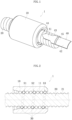
- an inspection jig 40 is inserted between a nut 10 and a screw shaft 20 of a ball screw device 1.
- a circumferential direction around a rotation axis of the ball screw device 1 is referred to as a "circumferential direction”
- a rotation axis direction of the ball screw device 1 is referred to as an "axial direction”.
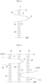
- the ball screw device 1 includes the nut 10, the screw shaft 20, and a plurality of balls 30.
- a spiral screw groove 11 is formed on an inner peripheral surface of the nut 10.
- a spiral screw groove 21 is formed on an outer peripheral surface of the screw shaft 20.
- a plurality of balls 30 is disposed on a rolling path formed by the screw groove 11 of the nut 10 and the screw groove 21 of the screw shaft 20.
- the end point and the start point of each rolling path communicate with each other through a return passage (not illustrated) to form a circulation path for circulating the balls 30.
- the return passage includes, for example, a known circulating member such as a U-shaped tube or a circulating piece embedded in the nut 10.
- circulation paths in the illustrated example, three rows of circulation paths S1, S2, and S3 are provided at a plurality of places separated in the axial direction.
- the circulation paths S1, S2, and S3 are formed by screw grooves 11 and 21 for one round (360°) and a return passage (not illustrated), and the same number of balls 30 are disposed in each of the circulation paths S1, S2, and S3.
- the screw grooves 11 and 21 in which no ball 30 is disposed are provided between the circulation paths S1, S2, and S3 in the axial direction.
- the inspection jig 40 has a plate shape as illustrated in FIG. 1 .
- the thickness of the inspection jig 40 is smaller than a radial gap between the inner peripheral surface of the nut 10 (minimum diameter portion of the screw groove 11) and the outer peripheral surface of the screw shaft 20 (maximum diameter portion of the screw groove 21).
- the inspection jig 40 has rigidity that does not deform when inserted between the balls 30 (described in detail later), and has a thickness of, for example, 1/2 or more of the radial gap between the inner peripheral surface of the nut 10 and the outer peripheral surface of the screw shaft 20.
- the inspection jig 40 includes a material softer than the nut 10, the screw shaft 20, and the ball 30, and includes, for example, resin.
- the inspection jig 40 includes a narrow portion 41 provided on an insertion direction leading side (hereinafter, referred to as a "distal end side”) and a wide portion 42 provided on an insertion direction rear side (hereinafter, referred to as a "proximal end side") of the narrow portion 41 and having a circumferential width wider than a circumferential width of the narrow portion.
- each of the narrow portion 41 and the wide portion 42 includes an axial region having a constant circumferential width.
- a stepped portion 43 connecting the narrow portion 41 and the wide portion 42 is provided between the narrow portion and the wide portion.
- the stepped portion 43 has a tapered shape whose circumferential width is widened toward a proximal end side (wide portion 42 side).
- a distal end 44 of the inspection jig 40 has a tapered shape in which the circumferential width decreases toward the distal end side.
- the circumferential width of the narrow portion 41 of the inspection jig 40 is larger than a total gap amount between the balls 30 when the number of balls 30 disposed in each of the circulation paths S1 to S3 is excessively large (for example, when the number is larger than an appropriate number by one). That is, when the number of balls 30 disposed in each of the circulation paths S1 to S3 is excessively large, the total gap amount between the balls 30 is smaller than the circumferential width of the narrow portion 41 of the inspection jig 40, and thus the narrow portion 41 of the inspection jig 40 cannot be inserted between the balls 30. In this case, as illustrated in FIG.
- the circumferential width of the narrow portion 41 of the inspection jig 40 is smaller than a total gap amount between the balls 30 when the number of balls 30 disposed in each of the circulation paths S1 to S3 is appropriate. That is, when the number of balls 30 disposed in each of the circulation paths S1 to S3 is appropriate, the total gap amount between the balls 30 is larger than the circumferential width of the narrow portion 41 of the inspection jig 40, and thus the narrow portion 41 of the inspection jig 40 is inserted between the balls 30 of the circulation paths S as illustrated in FIG. 4 .
- the circumferential width of the wide portion 42 of the inspection jig 40 is larger than the total gap amount between the balls 30 when the number of balls 30 disposed in each of the circulation paths S1 to S3 is appropriate. That is, when the number of balls 30 disposed in each of the circulation paths S1 to S3 is appropriate, the total gap amount between the balls 30 is smaller than the circumferential width of the wide portion 42 of the inspection jig 40, and thus the wide portion 42 of the inspection jig 40 cannot be inserted between the balls 30. In this case, as illustrated in FIG.
- the circumferential width of the wide portion 42 of the inspection jig 40 is smaller than a total gap amount between the balls 30 when the number of balls 30 arranged in each of the circulation paths S1 to S3 is excessively small (for example, when the number is smaller than an appropriate number by one). That is, when the number of balls 30 disposed in each of the circulation paths S1 to S3 is excessively small, the total gap amount between the balls 30 is larger than the circumferential width of the wide portion 42 of the inspection jig 40, and thus the wide portion 42 of the inspection jig 40 is inserted between the balls 30 in the circulation path S as illustrated in FIG. 5 .
- the inspection jig 40 by inserting the inspection jig 40 between the balls 30 in the circulation path S and confirming a stop position of the inspection jig, it is possible to determine whether the number of balls 30 in the circulation path S is appropriate. Specifically, when the inspection jig 40 is stopped before the narrow portion 41 is inserted between the balls 30, that is, in a state where the distal end 44 is inserted between the balls 30 (see FIG. 3 ), it can be determined that the number of balls 30 in the circulation path S is excessively large. When the inspection jig 40 is stopped in a state where the narrow portion 41 is inserted between the balls 30 (see FIG. 4 ), it can be determined that the balls 30 in the circulation path S are appropriate. When the inspection jig 40 is stopped in a state where the wide portion 42 is inserted between the balls 30 (see FIG. 5 ), it can be determined that the balls 30 in the circulation path S are excessively small.
- the number of balls 30 in the three rows of circulation paths S 1 to S3 is inspected by using the two inspection jigs 40.
- This inspection method will be described with reference to FIGS. 6 and 7 .
- the two inspection jigs 40 have a similar configuration, but here, reference signs "40(A)" and "40(B)" are given to distinguish the two inspection jigs 40 from each other.
- the movement of each of the inspection jigs 40(A) and 40(B) toward a side to be inserted into the gap between the nut 10 and the screw shaft 20 is referred to as "advancing", and the movement in the opposite direction is referred to as "retracting".
- one inspection jig 40(A) is advanced and inserted into the gap between the nut 10 and the screw shaft 20 from one side in the axial direction.
- the inspection jig 40(A) is stopped (step 101).
- the narrow portion is not inserted, it is determined that the number of balls 30 in the circulation path S1 is excessively large (step 103, see FIG. 3 ), and the inspection ends.
- step 104 it is confirmed whether the narrow portion 41 of the inspection jig 40(A) is inserted between the balls 30 in the circulation path S2 (step 104).
- step 105 determines that the number of balls 30 in the circulation path S2 is excessively large
- step 106 it is confirmed whether the wide portion 42 of the inspection jig 40 is inserted between the balls 30 in the circulation path S1 (step 106).
- step 107 see FIG. 5
- the inspection jig 40(B) is advanced while the narrow portion 41 of the inspection jig 40(A) is inserted between the balls 30 in the circulation paths S1 and S2, and is inserted into the gap between the nut 10 and the screw shaft 20 from the other side in the axial direction. Then, when a predetermined load or more is applied to the inspection jig 40(B), the inspection jig 40(B) is stopped. Thereafter, it is confirmed whether the narrow portion 41 of the inspection jig 40(B) is inserted between the balls 30 in the circulation path S3 (step 109). When the narrow portion is not inserted, it is determined that the number of balls 30 in the circulation path S3 is excessively large (step 110, see FIG. 3 ), and the inspection ends.
- the narrow portion 41 of the inspection jig 40(A) is already inserted between the balls 30 in the circulation path S2 (see FIG. 6 )
- the narrow portion 41 of the inspection jig 40(B) cannot be further inserted. Therefore, it is confirmed whether the narrow portion 41 of the inspection jig 40(B) is inserted between the balls 30 in the circulation path S2 (step 111).
- the narrow portion is not inserted, it is determined that the number of balls 30 in the circulation path S2 is excessively small (step 112), and the inspection ends.
- one of the inspection jigs 40(A) is retracted and pulled out from between the balls 30 in the circulation path S2 (step 113). Thereafter, the other inspection jig 40(B) is further advanced, and the inspection jig 40(B) is stopped when a predetermined load or more is applied (step 114). Then, it is confirmed whether the wide portion 42 of the inspection jig 40(B) is inserted between the balls 30 in the circulation path S3 (step 115). When the narrow portion is not inserted, it is determined that the number of balls 30 in the circulation path S3 is excessively small (step 116), and the inspection ends.
- step 117 when the wide portion 42 of the inspection jig 40(B) is not inserted between the balls 30 in the circulation path S3, it is determined from the current and previous results that the number of balls 30 in all the circulation paths S1 to S3 is not excessively large or excessively small but appropriate (step 117), and the inspection ends.
- the above inspection is automatically performed by using, for example, an inspection device illustrated in FIG. 8 .
- the inspection device includes a nut rotation unit 51 that rotates the nut 10 of the ball screw device 1, a screw shaft fixing portion (not illustrated) that fixes a screw shaft 20, an inspection jig holder (not illustrated) that holds the inspection jig 40 in a state of being movable in the axial direction and the circumferential direction, an inspection jig drive unit 52 that moves the inspection jig 40 in the axial direction, a controller 53 that controls the nut rotation unit 51 and the inspection jig drive unit 52, a sensor 54 that confirms a position of the inspection jig 40, a determiner 55 that determines whether the number of balls 30 is appropriate or inappropriate, and a display unit 56 such as a monitor that displays an inspection result.
- a screw shaft rotation unit that rotates the screw shaft 20 may be provided instead of the nut rotation unit 51, and a nut fixing portion may be provided instead of the screw shaft fixing portion.
- the inspection jig drive unit 52 biases the inspection jig 40 by a biasing means using elastic force such as a spring, air pressure, or hydraulic pressure. As a result, a load equal to or larger than the biasing force of the biasing means is not applied to the inspection jig 40. That is, when the inspection jig 40 is inserted between the balls in the circulation path, the inspection jig 40 is stopped when a load equal to or larger than the biasing force of the biasing means is applied.
- a load meter or a torque meter may be provided in the inspection jig drive unit 52, or a servomotor capable of detecting torque may be used as the inspection jig drive unit 52. In this case, the inspection jig drive unit 52 is only required to be controlled to stop the inspection jig 40 when it is detected that a load of a predetermined value or more is applied to the inspection jig 40.
- the ball screw device 1 and the inspection jig 40 are set in the inspection device, and the inspection jig 40 is disposed in an extension of the axial direction of the gap between the nut 10 of the ball screw device 1 and the screw shaft 20 in the radial direction (see FIG. 1 ). From this state, the inspection jig 40 is moved in the axial direction by the inspection jig drive unit 52, inserted into the gap between the nut 10 and the screw shaft 20, and inserted between the balls 30 disposed in the circulation paths S1 to S3.
- the circumferential position of the inspection jig 40 is automatically adjusted by the distal end 44 of the inspection jig 40 coming into contact with the ball 30, and the distal end 44 of the inspection jig 40 is easily inserted between the balls 30.
- the balls 30 easily move in the circulation path S1 by reciprocating the nut 10 in the rotation direction by the nut rotation unit 51. As a result, the inspection jig 40 is easily inserted between the balls 30 while moving the balls 30.
- the inspection jig 40 may be inserted between the balls 30 while being held relatively movable with respect to the screw shaft 20 and the nut 10 in the rotation direction of the ball screw device 1 (the circumferential direction about the axial centers of the screw shaft 20 and the nut 10).
- the sensor 54 detects the stop position of the inspection jig 40 at this time.
- the determiner 55 determines whether the number of balls 30 in the circulation paths S1 to S3 is appropriate on the basis of the stop position (that is, an insertion state) of the inspection jig 40 detected by the sensor 54, and the determination result is displayed on the display unit 56.
- FIG. 9 illustrates a case where the number of balls 30 in four rows of circulation paths S1 to S4 is inspected.
- the narrow portion 41 of one inspection jig 40(A) is inserted between the balls 30 in the intermediate circulation path S2 and the narrow portion 41 of the other inspection jig 40(B) is not inserted between the balls, it is possible to confirm that the number of balls 30 in the circulation path S2 is appropriate.
- the other intermediate circulation path S3 by confirming that the narrow portion 41 of the other inspection jig 40(B) is inserted between the balls 30 and the narrow portion 41 of the one inspection jig 40(A) is not inserted between the balls, it is possible to confirm that the number of balls 30 is appropriate.
- the ball screw device 1 has four or more rows of circulation paths, it is possible to determine whether the number of balls in the intermediate circulation path is appropriate or inappropriate by inserting the inspection jigs 40 from one side in the axial direction and the other side in the axial direction between the balls 30 in the intermediate circulation path and confirming the insertion state of each inspection jig 40 at this time.
- the present invention is not limited to this case.
- An operator may manually insert the inspection jig 40 between the nut 10 and the screw shaft 20 and determine the whether the number of balls is appropriate or inappropriate by the insertion state (for example, an insertion depth of the inspection jig 40).
- the stop position of the inspection jig 40 can be easily confirmed.
- the stop position of the inspection jig 40 can be confirmed by detecting the position of the mark provided on the inspection jig 40 with the sensor 54.
- the stop position of the inspection jig 40 can be confirmed by the operator visually confirming the position of the mark provided on the inspection jig 40.
- a mark 45 as illustrated in FIG. 1 can be provided on the inspection jig 40.
- the mark 45 is provided at a position overlapping with the axial end of the nut 10 in the radial direction in a state where the inspection jig 40 is appropriately inserted (for example, the state illustrated in FIG. 4 ). That is, when the axial end of the nut 10 and the mark 45 overlap when the inspection jig 40 is viewed from an outer peripheral side, it can be determined that the inspection jig 40 is appropriately inserted and the number of balls 30 in the circulation path S is appropriate.
- the number of balls may be inspected by using a plurality of inspection jigs having different circumferential widths. For example, an inspection jig having the same width as the narrow portion 41 and an inspection jig having the same width as the wide portion 42 are prepared, and the number of balls can be inspected by sequentially inserting these inspection jigs between the balls in the circulation path.
Landscapes
- Engineering & Computer Science (AREA)
- General Engineering & Computer Science (AREA)
- Mechanical Engineering (AREA)
- Physics & Mathematics (AREA)
- General Physics & Mathematics (AREA)
- Transmission Devices (AREA)
Abstract
Description
- The present invention relates to a method for inspecting a ball screw device, an inspection jig, and an inspection device.
- In a ball screw device, a large number of balls are disposed in a rolling passage formed by a screw groove formed on an inner peripheral surface of a nut and a screw groove formed on an outer peripheral surface of a screw shaft. The end point and the start point of the rolling passage communicate with each other through a return passage formed in a circulation member such as a tube, and a circulation path for circulating the balls through the rolling passage and the return passage is formed. As a method for incorporating a ball into a circulation path, for example,
Patent Literature 1 below discloses a method for incorporating a ball from an inner peripheral side of a nut. In addition,Patent Literature 2 below discloses a method in which an opening for ball insertion is provided on an outer peripheral surface of a nut, and a ball is incorporated into a circulation path from the opening. -
- Patent Literature 1:
JP 2530403 B2 - Patent Literature 2:
JP 2001-99256 A - When the balls are incorporated into the circulation path of the ball screw device, the number of balls incorporated into the circulation path may be excessively small or excessively large due to failure of assembly equipment or the like, or the balls may enter the screw groove not used as the circulation path. However, in an assembled state of the ball screw device, since the balls are hardly visible from the outside, it is difficult to confirm the number of balls.
- Therefore, an object of the present invention is to provide an inspection method for making it possible to easily confirm the number of balls in a circulation path after assembling a ball screw device.
- In order to achieve the above object, the present invention provides a method for inspecting a number of balls disposed in a circulation path of a ball screw device, the method including
inserting an inspection jig between the balls disposed in the circulation path through a gap between a nut and a screw shaft of the ball screw device, and inspecting the number of the balls by an insertion state of the inspection jig at a time of insertion. - In the ball screw device, a gap in a circumferential direction is provided between the balls in order to make the balls rollable in the circulation path. Therefore, when the number of balls disposed in the circulation path is larger than an appropriate number, a total gap amount between the balls becomes small, and when the number of balls disposed in the circulation path is smaller than the appropriate number, the total gap amount between the balls becomes large. When the inspection jig is inserted between the plurality of balls disposed in the circulation path through the gap between the nut and the screw shaft after the ball screw device is assembled, the insertion state of the inspection jig varies depending on the number of balls disposed in the circulation path. It is therefore possible to confirm whether the number of balls disposed in the circulation path is appropriate or inappropriate by the insertion state of the inspection jig inserted between the balls.
- The inspection jig includes, for example, a narrow portion and a wide portion provided on an insertion direction rear side of the narrow portion. A circumferential width of the narrow portion is larger than a total gap amount between the balls when the number of the balls disposed in the circulation path is excessively large, and is smaller than a total gap amount between the balls when the number of the balls disposed in the circulation path is appropriate. A circumferential width of the wide portion is larger than the total gap amount between the balls when the number of the balls disposed in the circulation path is appropriate, and is smaller than a total gap amount between the balls when the number of the balls disposed in the circulation path is excessively small. In a case where the inspection jig is used, when the narrow portion is not inserted between the balls in the circulation path, it can be determined that the number of balls is excessively large. When the narrow portion is inserted between the balls in the circulation path and the wide portion is not inserted, it can be determined that the number of balls is appropriate. When the wide portion is inserted between the balls in the circulation path, it can be determined that the number of balls is excessively small.
- The inspection jig may include a stepped portion that connects the narrow portion and the wide portion. By providing the stepped portion in this manner, it becomes clear how far the inspection jig can be inserted, and the number of balls can be easily determined by the inspection jig.
- The above inspection jig can be provided with a mark indicating an insertion depth for determining whether the number of balls is appropriate or inappropriate. In this case, whether the number of balls is appropriate or inappropriate can be determined by the position of the mark when the inspection jig is inserted.
- The number of balls may be inspected by using a plurality of the inspection jigs having different circumferential widths. In this case, whether the number of balls in the circulation path is appropriate or inappropriate can be confirmed by whether each inspection jig can be inserted between the balls.
- When three or more circulation paths are provided in different axial regions, the inspection jig can be directly inserted into the circulation path at an axial end, but the inspection jig cannot be directly inserted between the balls in an intermediate circulation path, and it is therefore difficult to inspect the number of balls. Therefore, it is preferable that the first inspection jig and the second inspection jig are used as the inspection jig, and the first inspection jig is inserted from one side in the axial direction and the second inspection jig is inserted from the other side in the axial direction between the balls in the intermediate circulation path. The number of balls disposed in the intermediate circulation path can be inspected by the insertion state of each inspection jig at this time.
- When the inspection jig is inserted between the balls, it is necessary to move the balls in the circulation path. At this time, by inserting the inspection jig between the balls while relatively reciprocating the screw shaft and the nut in a rotation direction, the balls easily roll in the circulation path, and the inspection jig is easily inserted between the balls. The inspection jig may be inserted between the balls while the inspection jig is held in a relatively movable state in the rotation direction of the ball screw device with respect to the screw shaft and the nut of the ball screw device.
- In the above inspection method, the inspection jig is inserted between the balls in the circulation path, and the inspection jig can be stopped when a predetermined load is applied to the inspection jig. Whether the number of balls in the circulation path is appropriate or inappropriate can be determined by a stop position of the inspection jig.
- The above inspection method can be automatically performed by an inspection device for a ball screw device, the inspection device including an inspection jig, a drive unit that inserts the inspection jig between the balls disposed in the circulation path, and a determiner that determines whether the number of the balls in the circulation path is appropriate or inappropriate by an insertion state of the inspection jig.
- As described above, the present invention makes it possible to easily confirm the number of balls in the circulation path after assembling the ball screw device.
-
-
FIG. 1 is a perspective view of a ball screw device and an inspection jig. -
FIG. 2 is a sectional view of the ball screw device. -
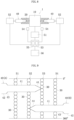
FIG. 3 is a schematic diagram illustrating an insertion state of the inspection jig in a case where the number of balls is excessively small. -
FIG. 4 is a schematic diagram illustrating an insertion state of the inspection jig in a case where the number of balls is appropriate. -
FIG. 5 is a schematic diagram illustrating an insertion state of the inspection jig in a case where the number of balls is excessively large. -
FIG. 6 is a schematic diagram illustrating a state in which the number of balls in three rows of circulation paths is inspected. -
FIG. 7 is a flowchart illustrating an inspection procedure of the number of balls in three rows of circulation paths. -
FIG. 8 is a block diagram of an inspection device. -
FIG. 9 is a schematic diagram illustrating a state in which the number of balls in four rows of circulation paths is inspected. - Hereinafter, an embodiment of the present invention will be described with reference to the drawings.
- In an inspection method according to an embodiment of the present invention, as illustrated in
FIG. 1 , aninspection jig 40 is inserted between anut 10 and ascrew shaft 20 of aball screw device 1. In the present specification, a circumferential direction around a rotation axis of theball screw device 1 is referred to as a "circumferential direction", and a rotation axis direction of theball screw device 1 is referred to as an "axial direction". - As illustrated in
FIG. 2 , theball screw device 1 includes thenut 10, thescrew shaft 20, and a plurality ofballs 30. Aspiral screw groove 11 is formed on an inner peripheral surface of thenut 10. Aspiral screw groove 21 is formed on an outer peripheral surface of thescrew shaft 20. A plurality ofballs 30 is disposed on a rolling path formed by thescrew groove 11 of thenut 10 and thescrew groove 21 of thescrew shaft 20. The end point and the start point of each rolling path communicate with each other through a return passage (not illustrated) to form a circulation path for circulating theballs 30. The return passage includes, for example, a known circulating member such as a U-shaped tube or a circulating piece embedded in thenut 10. - In the present embodiment, circulation paths (in the illustrated example, three rows of circulation paths S1, S2, and S3) are provided at a plurality of places separated in the axial direction. In the illustrated example, the circulation paths S1, S2, and S3 are formed by
screw grooves balls 30 are disposed in each of the circulation paths S1, S2, and S3. Thescrew grooves ball 30 is disposed are provided between the circulation paths S1, S2, and S3 in the axial direction. - The
inspection jig 40 has a plate shape as illustrated inFIG. 1 . The thickness of theinspection jig 40 is smaller than a radial gap between the inner peripheral surface of the nut 10 (minimum diameter portion of the screw groove 11) and the outer peripheral surface of the screw shaft 20 (maximum diameter portion of the screw groove 21). Theinspection jig 40 has rigidity that does not deform when inserted between the balls 30 (described in detail later), and has a thickness of, for example, 1/2 or more of the radial gap between the inner peripheral surface of thenut 10 and the outer peripheral surface of thescrew shaft 20. Theinspection jig 40 includes a material softer than thenut 10, thescrew shaft 20, and theball 30, and includes, for example, resin. - The
inspection jig 40 includes anarrow portion 41 provided on an insertion direction leading side (hereinafter, referred to as a "distal end side") and awide portion 42 provided on an insertion direction rear side (hereinafter, referred to as a "proximal end side") of thenarrow portion 41 and having a circumferential width wider than a circumferential width of the narrow portion. In the illustrated example, each of thenarrow portion 41 and thewide portion 42 includes an axial region having a constant circumferential width. A steppedportion 43 connecting thenarrow portion 41 and thewide portion 42 is provided between the narrow portion and the wide portion. The steppedportion 43 has a tapered shape whose circumferential width is widened toward a proximal end side (wide portion 42 side). Adistal end 44 of theinspection jig 40 has a tapered shape in which the circumferential width decreases toward the distal end side. - The circumferential width of the
narrow portion 41 of theinspection jig 40 is larger than a total gap amount between theballs 30 when the number ofballs 30 disposed in each of the circulation paths S1 to S3 is excessively large (for example, when the number is larger than an appropriate number by one). That is, when the number ofballs 30 disposed in each of the circulation paths S1 to S3 is excessively large, the total gap amount between theballs 30 is smaller than the circumferential width of thenarrow portion 41 of theinspection jig 40, and thus thenarrow portion 41 of theinspection jig 40 cannot be inserted between theballs 30. In this case, as illustrated inFIG. 3 , when theinspection jig 40 is inserted between theballs 30 in a circulation path S (circulation path having a similar configuration to the circulation paths S1 to S3) from one side in the axial direction (left side in the drawing), theinspection jig 40 is stopped in a state where the inspection jig is inserted between theballs 30 halfway through thedistal end 44. - The circumferential width of the
narrow portion 41 of theinspection jig 40 is smaller than a total gap amount between theballs 30 when the number ofballs 30 disposed in each of the circulation paths S1 to S3 is appropriate. That is, when the number ofballs 30 disposed in each of the circulation paths S1 to S3 is appropriate, the total gap amount between theballs 30 is larger than the circumferential width of thenarrow portion 41 of theinspection jig 40, and thus thenarrow portion 41 of theinspection jig 40 is inserted between theballs 30 of the circulation paths S as illustrated inFIG. 4 . - The circumferential width of the
wide portion 42 of theinspection jig 40 is larger than the total gap amount between theballs 30 when the number ofballs 30 disposed in each of the circulation paths S1 to S3 is appropriate. That is, when the number ofballs 30 disposed in each of the circulation paths S1 to S3 is appropriate, the total gap amount between theballs 30 is smaller than the circumferential width of thewide portion 42 of theinspection jig 40, and thus thewide portion 42 of theinspection jig 40 cannot be inserted between theballs 30. In this case, as illustrated inFIG. 4 , when theinspection jig 40 is inserted between theballs 30 on the circulation path S from one side in the axial direction (left side in the drawing), theinspection jig 40 is stopped in a state where the steppedportion 43 between thenarrow portion 41 and thewide portion 42 abuts on theball 30. - The circumferential width of the
wide portion 42 of theinspection jig 40 is smaller than a total gap amount between theballs 30 when the number ofballs 30 arranged in each of the circulation paths S1 to S3 is excessively small (for example, when the number is smaller than an appropriate number by one). That is, when the number ofballs 30 disposed in each of the circulation paths S1 to S3 is excessively small, the total gap amount between theballs 30 is larger than the circumferential width of thewide portion 42 of theinspection jig 40, and thus thewide portion 42 of theinspection jig 40 is inserted between theballs 30 in the circulation path S as illustrated inFIG. 5 . - As described above, by inserting the
inspection jig 40 between theballs 30 in the circulation path S and confirming a stop position of the inspection jig, it is possible to determine whether the number ofballs 30 in the circulation path S is appropriate. Specifically, when theinspection jig 40 is stopped before thenarrow portion 41 is inserted between theballs 30, that is, in a state where thedistal end 44 is inserted between the balls 30 (seeFIG. 3 ), it can be determined that the number ofballs 30 in the circulation path S is excessively large. When theinspection jig 40 is stopped in a state where thenarrow portion 41 is inserted between the balls 30 (seeFIG. 4 ), it can be determined that theballs 30 in the circulation path S are appropriate. When theinspection jig 40 is stopped in a state where thewide portion 42 is inserted between the balls 30 (seeFIG. 5 ), it can be determined that theballs 30 in the circulation path S are excessively small. - In the present embodiment, the number of
balls 30 in the three rows ofcirculation paths S 1 to S3 is inspected by using the two inspection jigs 40. This inspection method will be described with reference toFIGS. 6 and7 . Note that the twoinspection jigs 40 have a similar configuration, but here, reference signs "40(A)" and "40(B)" are given to distinguish the twoinspection jigs 40 from each other. The movement of each of the inspection jigs 40(A) and 40(B) toward a side to be inserted into the gap between thenut 10 and thescrew shaft 20 is referred to as "advancing", and the movement in the opposite direction is referred to as "retracting". - First, one inspection jig 40(A) is advanced and inserted into the gap between the
nut 10 and thescrew shaft 20 from one side in the axial direction. When a predetermined load or more is applied to the inspection jig 40(A), the inspection jig 40(A) is stopped (step 101). Thereafter, it is confirmed whether thenarrow portion 41 of the inspection jig 40(A) is inserted between theballs 30 in the circulation path S1 (step 102). When the narrow portion is not inserted, it is determined that the number ofballs 30 in the circulation path S1 is excessively large (step 103, seeFIG. 3 ), and the inspection ends. Next, it is confirmed whether thenarrow portion 41 of the inspection jig 40(A) is inserted between theballs 30 in the circulation path S2 (step 104). When the narrow portion is not inserted, it is determined that the number ofballs 30 in the circulation path S2 is excessively large (step 105, seeFIG. 3 ), and the inspection ends. Subsequently, it is confirmed whether thewide portion 42 of theinspection jig 40 is inserted between theballs 30 in the circulation path S1 (step 106). When the narrow portion is not inserted, it is determined that the number ofballs 30 in the circulation path S1 is excessively small (step 107, seeFIG. 5 ), and the inspection ends. - On the other hand, as illustrated in
FIG. 6 , when thenarrow portion 41 is inserted between theballs 30 in the circulation paths S1 and S2 and thewide portion 42 is not inserted between theballs 30 in the circulation path S1, the processing proceeds to the next step. - In the
next step 108, the inspection jig 40(B) is advanced while thenarrow portion 41 of the inspection jig 40(A) is inserted between theballs 30 in the circulation paths S1 and S2, and is inserted into the gap between thenut 10 and thescrew shaft 20 from the other side in the axial direction. Then, when a predetermined load or more is applied to the inspection jig 40(B), the inspection jig 40(B) is stopped. Thereafter, it is confirmed whether thenarrow portion 41 of the inspection jig 40(B) is inserted between theballs 30 in the circulation path S3 (step 109). When the narrow portion is not inserted, it is determined that the number ofballs 30 in the circulation path S3 is excessively large (step 110, seeFIG. 3 ), and the inspection ends. - At this time, since the
narrow portion 41 of the inspection jig 40(A) is already inserted between theballs 30 in the circulation path S2 (seeFIG. 6 ), when the number ofballs 30 in the circulation path S2 is appropriate, thenarrow portion 41 of the inspection jig 40(B) cannot be further inserted. Therefore, it is confirmed whether thenarrow portion 41 of the inspection jig 40(B) is inserted between theballs 30 in the circulation path S2 (step 111). When the narrow portion is not inserted, it is determined that the number ofballs 30 in the circulation path S2 is excessively small (step 112), and the inspection ends. - On the other hand, as illustrated in
FIG. 6 , when thenarrow portion 41 of the inspection jig 40(B) is inserted between theballs 30 in the circulation path S3 and is not inserted between theballs 30 in the circulation path S2, the processing proceeds to the next step. - Next, one of the inspection jigs 40(A) is retracted and pulled out from between the
balls 30 in the circulation path S2 (step 113). Thereafter, the other inspection jig 40(B) is further advanced, and the inspection jig 40(B) is stopped when a predetermined load or more is applied (step 114). Then, it is confirmed whether thewide portion 42 of the inspection jig 40(B) is inserted between theballs 30 in the circulation path S3 (step 115). When the narrow portion is not inserted, it is determined that the number ofballs 30 in the circulation path S3 is excessively small (step 116), and the inspection ends. - On the other hand, when the
wide portion 42 of the inspection jig 40(B) is not inserted between theballs 30 in the circulation path S3, it is determined from the current and previous results that the number ofballs 30 in all the circulation paths S1 to S3 is not excessively large or excessively small but appropriate (step 117), and the inspection ends. - The above inspection is automatically performed by using, for example, an inspection device illustrated in
FIG. 8 . The inspection device includes anut rotation unit 51 that rotates thenut 10 of theball screw device 1, a screw shaft fixing portion (not illustrated) that fixes ascrew shaft 20, an inspection jig holder (not illustrated) that holds theinspection jig 40 in a state of being movable in the axial direction and the circumferential direction, an inspectionjig drive unit 52 that moves theinspection jig 40 in the axial direction, acontroller 53 that controls thenut rotation unit 51 and the inspectionjig drive unit 52, asensor 54 that confirms a position of theinspection jig 40, adeterminer 55 that determines whether the number ofballs 30 is appropriate or inappropriate, and adisplay unit 56 such as a monitor that displays an inspection result. Note that a screw shaft rotation unit that rotates thescrew shaft 20 may be provided instead of thenut rotation unit 51, and a nut fixing portion may be provided instead of the screw shaft fixing portion. - The inspection
jig drive unit 52 biases theinspection jig 40 by a biasing means using elastic force such as a spring, air pressure, or hydraulic pressure. As a result, a load equal to or larger than the biasing force of the biasing means is not applied to theinspection jig 40. That is, when theinspection jig 40 is inserted between the balls in the circulation path, theinspection jig 40 is stopped when a load equal to or larger than the biasing force of the biasing means is applied. In addition, a load meter or a torque meter may be provided in the inspectionjig drive unit 52, or a servomotor capable of detecting torque may be used as the inspectionjig drive unit 52. In this case, the inspectionjig drive unit 52 is only required to be controlled to stop theinspection jig 40 when it is detected that a load of a predetermined value or more is applied to theinspection jig 40. - The
ball screw device 1 and theinspection jig 40 are set in the inspection device, and theinspection jig 40 is disposed in an extension of the axial direction of the gap between thenut 10 of theball screw device 1 and thescrew shaft 20 in the radial direction (seeFIG. 1 ). From this state, theinspection jig 40 is moved in the axial direction by the inspectionjig drive unit 52, inserted into the gap between thenut 10 and thescrew shaft 20, and inserted between theballs 30 disposed in the circulation paths S1 to S3. At this time, since theinspection jig 40 is held in a state of being movable in the circumferential direction, the circumferential position of theinspection jig 40 is automatically adjusted by thedistal end 44 of theinspection jig 40 coming into contact with theball 30, and thedistal end 44 of theinspection jig 40 is easily inserted between theballs 30. When theinspection jig 40 is inserted between theballs 30, theballs 30 easily move in the circulation path S1 by reciprocating thenut 10 in the rotation direction by thenut rotation unit 51. As a result, theinspection jig 40 is easily inserted between theballs 30 while moving theballs 30. At this time, theinspection jig 40 may be inserted between theballs 30 while being held relatively movable with respect to thescrew shaft 20 and thenut 10 in the rotation direction of the ball screw device 1 (the circumferential direction about the axial centers of thescrew shaft 20 and the nut 10). - Then, when the
inspection jig 40 stops, thesensor 54 detects the stop position of theinspection jig 40 at this time. Thedeterminer 55 determines whether the number ofballs 30 in the circulation paths S1 to S3 is appropriate on the basis of the stop position (that is, an insertion state) of theinspection jig 40 detected by thesensor 54, and the determination result is displayed on thedisplay unit 56. - The present invention is not limited to the above embodiment. Hereinafter, other embodiments of the present invention will be described, but points similar to those of the above embodiment will not be repeated.
- For example,
FIG. 9 illustrates a case where the number ofballs 30 in four rows of circulation paths S1 to S4 is inspected. In this case, by confirming that thenarrow portion 41 of one inspection jig 40(A) is inserted between theballs 30 in the intermediate circulation path S2 and thenarrow portion 41 of the other inspection jig 40(B) is not inserted between the balls, it is possible to confirm that the number ofballs 30 in the circulation path S2 is appropriate. Similarly for the other intermediate circulation path S3, by confirming that thenarrow portion 41 of the other inspection jig 40(B) is inserted between theballs 30 and thenarrow portion 41 of the one inspection jig 40(A) is not inserted between the balls, it is possible to confirm that the number ofballs 30 is appropriate. - Therefore, even when the
ball screw device 1 has four or more rows of circulation paths, it is possible to determine whether the number of balls in the intermediate circulation path is appropriate or inappropriate by inserting the inspection jigs 40 from one side in the axial direction and the other side in the axial direction between theballs 30 in the intermediate circulation path and confirming the insertion state of eachinspection jig 40 at this time. - In the above embodiment, a case where the number of balls in the circulation path is automatically inspected by the inspection device has been described, but the present invention is not limited to this case. An operator may manually insert the
inspection jig 40 between thenut 10 and thescrew shaft 20 and determine the whether the number of balls is appropriate or inappropriate by the insertion state (for example, an insertion depth of the inspection jig 40). - By providing a mark for confirming the insertion depth on the
inspection jig 40, the stop position of theinspection jig 40 can be easily confirmed. For example, when the inspection is automatically performed, the stop position of theinspection jig 40 can be confirmed by detecting the position of the mark provided on theinspection jig 40 with thesensor 54. When the inspection is manually performed, the stop position of theinspection jig 40 can be confirmed by the operator visually confirming the position of the mark provided on theinspection jig 40. - For example, a
mark 45 as illustrated inFIG. 1 can be provided on theinspection jig 40. Themark 45 is provided at a position overlapping with the axial end of thenut 10 in the radial direction in a state where theinspection jig 40 is appropriately inserted (for example, the state illustrated inFIG. 4 ). That is, when the axial end of thenut 10 and themark 45 overlap when theinspection jig 40 is viewed from an outer peripheral side, it can be determined that theinspection jig 40 is appropriately inserted and the number ofballs 30 in the circulation path S is appropriate. On the other hand, when themark 45 is separated from thenut 10 in the axial direction or themark 45 is hidden behind an inner periphery of thenut 10 and cannot be seen when theinspection jig 40 is viewed from the outer peripheral side, it can be determined that theinspection jig 40 is not appropriately inserted and the number of balls in the circulation path S is not appropriate. - In the above embodiment, a case where the
inspection jig 40 having thenarrow portion 41 and thewide portion 42 is used has been described, but the present invention is not limited to this case. The number of balls may be inspected by using a plurality of inspection jigs having different circumferential widths. For example, an inspection jig having the same width as thenarrow portion 41 and an inspection jig having the same width as thewide portion 42 are prepared, and the number of balls can be inspected by sequentially inserting these inspection jigs between the balls in the circulation path. -
- 1
- Ball screw device
- 10
- Nut
- 11
- Screw groove
- 20
- Screw shaft
- 21
- Screw groove
- 30
- Ball
- 40
- Inspection jig
- 41
- Narrow portion
- 42
- Wide portion
- 43
- Stepped portion
- 44
- Distal end
- 51
- Nut rotation unit
- 52
- Inspection jig drive unit
- 53
- Controller
- 54
- Sensor
- 55
- Determiner
- 56
- Display unit
- S, S1 to S4
- Circulation path
Claims (11)
- A method for inspecting a number of balls disposed in a circulation path of a ball screw device, the method comprising inserting an inspection jig between the balls disposed in the circulation path through a gap between a nut and a screw shaft of the ball screw device, and inspecting the number of the balls by an insertion state of the inspection jig at a time of insertion.
- The method for inspecting a ball screw device according to claim 1, whereinthe inspection jig includes a narrow portion and a wide portion provided on an insertion direction rear side of the narrow portion,a circumferential width of the narrow portion is larger than a total gap amount between the balls when the number of the balls disposed in the circulation path is excessively large, and is smaller than a total gap amount between the balls when the number of the balls disposed in the circulation path is appropriate, anda circumferential width of the wide portion is larger than a total gap amount between the balls when the number of the balls disposed in the circulation path is appropriate, and is smaller than a total gap amount between the balls when the number of the balls disposed in the circulation path is excessively small.
- The method for inspecting a ball screw device according to claim 2, wherein the inspection jig includes a stepped portion that connects the narrow portion and the wide portion.
- The method for inspecting a ball screw device according to any one of claims 1 to 3, wherein the inspection jig is provided with a mark for confirming an insertion depth.
- The method for inspecting a ball screw device according to claim 1, wherein the number of the balls is inspected by using a plurality of the inspection jigs having different circumferential widths.
- The method for inspecting a ball screw device according to any one of claims 1 to 5, whereinthe ball screw device has three or more of the circulation paths provided in different axial regions,a first inspection jig and a second inspection jig are used as the inspection jig, andthe first inspection jig is inserted between the balls in an intermediate circulation path from one side in an axial direction and the second inspection jig is inserted between the balls in the intermediate circulation path from another side in the axial direction, and the number of the balls disposed in the intermediate circulation path is inspected by an insertion state of each of the first inspection jig and the second inspection jig at a time of insertion.
- The method for inspecting a ball screw device according to any one of claims 1 to 6, wherein the inspection jig is inserted between the balls while the screw shaft and the nut of the ball screw device are relatively reciprocated in a rotation direction.
- The method for inspecting a ball screw device according to any one of claims 1 to 7, wherein the inspection jig is inserted between the balls while the inspection jig is held in a relatively movable state in the rotation direction of the ball screw device with respect to the screw shaft and the nut of the ball screw device.
- The method for inspecting a ball screw device according to any one of claims 1 to 8, wherein the inspection jig is inserted between the balls in the circulation path, and the inspection jig is stopped when a predetermined load is applied to the inspection jig.
- An inspection jig that is inserted between balls disposed in a circulation path of a ball screw device and inspects a number of the balls, whereinthe inspection jig includes a narrow portion and a wide portion provided on an insertion direction rear side of the narrow portion,a circumferential width of the narrow portion is larger than a total gap amount between the balls when the number of the balls disposed in the circulation path is excessively large, and is smaller than a total gap amount between the balls when the number of the balls disposed in the circulation path is appropriate, anda circumferential width of the wide portion is larger than a total gap amount between the balls when the number of the balls disposed in the circulation path is appropriate, and is smaller than a total gap amount between the balls when the number of the balls disposed in the circulation path is excessively small.
- An inspection device for a ball screw device, the inspection device inspecting a number of balls disposed in a circulation path of the ball screw device, the inspection device comprising: an inspection jig; an inspection jig drive unit that inserts the inspection jig between the balls disposed in the circulation path; and a determiner that determines whether the number of the balls in the circulation path is appropriate or inappropriate by an insertion state of the inspection jig.
Applications Claiming Priority (2)
| Application Number | Priority Date | Filing Date | Title |
|---|---|---|---|
| JP2022051627A JP7811496B2 (en) | 2022-03-28 | 2022-03-28 | Ball screw device inspection method, inspection jig, and inspection device |
| PCT/JP2023/007422 WO2023189121A1 (en) | 2022-03-28 | 2023-02-28 | Method for inspecting ball screw device, inspection jig, and inspection device |
Publications (2)
| Publication Number | Publication Date |
|---|---|
| EP4502422A1 true EP4502422A1 (en) | 2025-02-05 |
| EP4502422A4 EP4502422A4 (en) | 2025-07-09 |
Family
ID=88200620
Family Applications (1)
| Application Number | Title | Priority Date | Filing Date |
|---|---|---|---|
| EP23779151.2A Pending EP4502422A4 (en) | 2022-03-28 | 2023-02-28 | Method for inspecting a ball screw device, inspection fixture, and inspection device |
Country Status (5)
| Country | Link |
|---|---|
| US (1) | US20250198489A1 (en) |
| EP (1) | EP4502422A4 (en) |
| JP (1) | JP7811496B2 (en) |
| CN (1) | CN118946747A (en) |
| WO (1) | WO2023189121A1 (en) |
Families Citing this family (1)
| Publication number | Priority date | Publication date | Assignee | Title |
|---|---|---|---|---|
| JP2018157979A (en) * | 2017-03-23 | 2018-10-11 | 株式会社三洋物産 | Game machine |
Family Cites Families (5)
| Publication number | Priority date | Publication date | Assignee | Title |
|---|---|---|---|---|
| JPH0650108Y2 (en) * | 1989-12-06 | 1994-12-21 | 本田技研工業株式会社 | Ball screw assembly device |
| JP2530403B2 (en) | 1991-11-20 | 1996-09-04 | 本田技研工業株式会社 | Ball screw ball insertion device |
| JP2001099256A (en) | 1999-09-30 | 2001-04-10 | Nsk Ltd | Assembling method of ball screw device |
| JP2006242276A (en) * | 2005-03-03 | 2006-09-14 | Taiyoo Kikai Kk | Equivalent arrangement device and bearing manufacturing device using it |
| JP6346822B2 (en) * | 2014-08-04 | 2018-06-20 | 日本トムソン株式会社 | Linear bushing |
-
2022
- 2022-03-28 JP JP2022051627A patent/JP7811496B2/en active Active
-
2023
- 2023-02-28 EP EP23779151.2A patent/EP4502422A4/en active Pending
- 2023-02-28 CN CN202380028257.5A patent/CN118946747A/en active Pending
- 2023-02-28 WO PCT/JP2023/007422 patent/WO2023189121A1/en not_active Ceased
- 2023-02-28 US US18/847,353 patent/US20250198489A1/en active Pending
Also Published As
| Publication number | Publication date |
|---|---|
| CN118946747A (en) | 2024-11-12 |
| WO2023189121A1 (en) | 2023-10-05 |
| EP4502422A4 (en) | 2025-07-09 |
| US20250198489A1 (en) | 2025-06-19 |
| JP7811496B2 (en) | 2026-02-05 |
| JP2023144577A (en) | 2023-10-11 |
Similar Documents
| Publication | Publication Date | Title |
|---|---|---|
| US10782207B2 (en) | Method for inspecting ball screw mechanism, apparatus for inspecting ball screw mechanism, and method for inspecting steering system | |
| EP1835256A1 (en) | Screw measuring method, screw measuring probe, and screw measuring apparatus using the screw measuring probe | |
| EP1267089B1 (en) | Method for measuring axial force of a bearing device | |
| EP0447048B1 (en) | Method and apparatus for gaging bodies such as threaded fasteners and blanks | |
| US20250198489A1 (en) | Method for inspecting ball screw device, inspection jig, and inspection device | |
| DE102010017113B4 (en) | Transmission with a sensor device | |
| EP1775490A1 (en) | Hydraulic nut for mounting conical objects | |
| US20230258600A1 (en) | Apparatus and method for inspecting an inner wall surface of a pipe | |
| JPH09196605A (en) | Measuring method and assembling method of double-row angular contact ball bearing | |
| EP2131178A1 (en) | Diagnostic method for at least one ball bearing, in particular for an angular ball bearing, a corresponding diagnostic system and the use of such a diagnostic system | |
| EP2756890B1 (en) | Method and measuring roller for the determination of flatness deviation of a strip-shaped material | |
| US20130206731A1 (en) | Wire electric discharge machine performing distortion removing machining | |
| KR100278161B1 (en) | Method of Judging the Lip Turnover of a Seal and Apparatus for Inserting a Seal | |
| US10215546B2 (en) | Rotor profile comparator | |
| KR101859626B1 (en) | Counting apparatus for tap-hole screw thread and defect | |
| WO2018193315A1 (en) | Equipment and method for producing spherical bodies | |
| CN107246856A (en) | A kind of expansible support inner chamber formula tubular elements positioner and localization method | |
| JPH05332702A (en) | Ball screw processing accuracy inspection instrument | |
| CN107186653A (en) | A kind of multi-point support intracavity tubular elements positioner and localization method | |
| CN207104720U (en) | A kind of multi-point support intracavity tubular elements positioner | |
| JP3009339B2 (en) | Nut screw thread groove inspection device | |
| EP4317742A1 (en) | Multi-row ball screw | |
| KR0184723B1 (en) | Machining device for grooves bearing member | |
| JP7816343B2 (en) | Multi-row bearings and bearing units | |
| CN219416031U (en) | Measuring tool for rapidly measuring small diameter of deep and long internal threaded hole |
Legal Events
| Date | Code | Title | Description |
|---|---|---|---|
| STAA | Information on the status of an ep patent application or granted ep patent |
Free format text: STATUS: THE INTERNATIONAL PUBLICATION HAS BEEN MADE |
|
| PUAI | Public reference made under article 153(3) epc to a published international application that has entered the european phase |
Free format text: ORIGINAL CODE: 0009012 |
|
| STAA | Information on the status of an ep patent application or granted ep patent |
Free format text: STATUS: REQUEST FOR EXAMINATION WAS MADE |
|
| 17P | Request for examination filed |
Effective date: 20241022 |
|
| AK | Designated contracting states |
Kind code of ref document: A1 Designated state(s): AL AT BE BG CH CY CZ DE DK EE ES FI FR GB GR HR HU IE IS IT LI LT LU LV MC ME MK MT NL NO PL PT RO RS SE SI SK SM TR |
|
| REG | Reference to a national code |
Ref country code: DE Ref legal event code: R079 Free format text: PREVIOUS MAIN CLASS: F16H0025220000 Ipc: G01M0013020000 |
|
| DAV | Request for validation of the european patent (deleted) | ||
| DAX | Request for extension of the european patent (deleted) | ||
| A4 | Supplementary search report drawn up and despatched |
Effective date: 20250605 |
|
| RIC1 | Information provided on ipc code assigned before grant |
Ipc: F16H 25/24 20060101ALI20250530BHEP Ipc: F16H 25/22 20060101ALI20250530BHEP Ipc: G01M 99/00 20110101ALI20250530BHEP Ipc: G01M 13/02 20190101AFI20250530BHEP |