EP4502414A2 - HIGH OFFSET BRAKE ADJUSTER WITH ADDITIONAL LOW OFFSET ARM TO REDUCE LATERAL LOADS - Google Patents
HIGH OFFSET BRAKE ADJUSTER WITH ADDITIONAL LOW OFFSET ARM TO REDUCE LATERAL LOADS Download PDFInfo
- Publication number
- EP4502414A2 EP4502414A2 EP24220946.8A EP24220946A EP4502414A2 EP 4502414 A2 EP4502414 A2 EP 4502414A2 EP 24220946 A EP24220946 A EP 24220946A EP 4502414 A2 EP4502414 A2 EP 4502414A2
- Authority
- EP
- European Patent Office
- Prior art keywords
- brake
- brake lever
- hole
- shaft
- central axis
- Prior art date
- Legal status (The legal status is an assumption and is not a legal conclusion. Google has not performed a legal analysis and makes no representation as to the accuracy of the status listed.)
- Pending
Links
Images


Classifications
-
- F—MECHANICAL ENGINEERING; LIGHTING; HEATING; WEAPONS; BLASTING
- F16—ENGINEERING ELEMENTS AND UNITS; GENERAL MEASURES FOR PRODUCING AND MAINTAINING EFFECTIVE FUNCTIONING OF MACHINES OR INSTALLATIONS; THERMAL INSULATION IN GENERAL
- F16D—COUPLINGS FOR TRANSMITTING ROTATION; CLUTCHES; BRAKES
- F16D51/00—Brakes with outwardly-movable braking members co-operating with the inner surface of a drum or the like
- F16D51/16—Brakes with outwardly-movable braking members co-operating with the inner surface of a drum or the like shaped as brake-shoes pivoted on a fixed or nearly-fixed axis
- F16D51/18—Brakes with outwardly-movable braking members co-operating with the inner surface of a drum or the like shaped as brake-shoes pivoted on a fixed or nearly-fixed axis with two brake-shoes
- F16D51/20—Brakes with outwardly-movable braking members co-operating with the inner surface of a drum or the like shaped as brake-shoes pivoted on a fixed or nearly-fixed axis with two brake-shoes extending in opposite directions from their pivots
- F16D51/22—Brakes with outwardly-movable braking members co-operating with the inner surface of a drum or the like shaped as brake-shoes pivoted on a fixed or nearly-fixed axis with two brake-shoes extending in opposite directions from their pivots mechanically actuated
-
- F—MECHANICAL ENGINEERING; LIGHTING; HEATING; WEAPONS; BLASTING
- F16—ENGINEERING ELEMENTS AND UNITS; GENERAL MEASURES FOR PRODUCING AND MAINTAINING EFFECTIVE FUNCTIONING OF MACHINES OR INSTALLATIONS; THERMAL INSULATION IN GENERAL
- F16D—COUPLINGS FOR TRANSMITTING ROTATION; CLUTCHES; BRAKES
- F16D65/00—Parts or details
- F16D65/38—Slack adjusters
- F16D65/40—Slack adjusters mechanical
- F16D65/42—Slack adjusters mechanical non-automatic
- F16D65/50—Slack adjusters mechanical non-automatic for angular adjustment of two concentric parts of the brake control system
-
- F—MECHANICAL ENGINEERING; LIGHTING; HEATING; WEAPONS; BLASTING
- F16—ENGINEERING ELEMENTS AND UNITS; GENERAL MEASURES FOR PRODUCING AND MAINTAINING EFFECTIVE FUNCTIONING OF MACHINES OR INSTALLATIONS; THERMAL INSULATION IN GENERAL
- F16D—COUPLINGS FOR TRANSMITTING ROTATION; CLUTCHES; BRAKES
- F16D65/00—Parts or details
- F16D65/38—Slack adjusters
- F16D65/40—Slack adjusters mechanical
- F16D65/52—Slack adjusters mechanical self-acting in one direction for adjusting excessive play
- F16D65/60—Slack adjusters mechanical self-acting in one direction for adjusting excessive play for angular adjustment of two concentric parts of the brake control systems
-
- B—PERFORMING OPERATIONS; TRANSPORTING
- B60—VEHICLES IN GENERAL
- B60T—VEHICLE BRAKE CONTROL SYSTEMS OR PARTS THEREOF; BRAKE CONTROL SYSTEMS OR PARTS THEREOF, IN GENERAL; ARRANGEMENT OF BRAKING ELEMENTS ON VEHICLES IN GENERAL; PORTABLE DEVICES FOR PREVENTING UNWANTED MOVEMENT OF VEHICLES; VEHICLE MODIFICATIONS TO FACILITATE COOLING OF BRAKES
- B60T17/00—Component parts, details, or accessories of power brake systems not covered by groups B60T8/00, B60T13/00 or B60T15/00, or presenting other characteristic features
- B60T17/18—Safety devices; Monitoring
- B60T17/22—Devices for monitoring or checking brake systems; Signal devices
-
- F—MECHANICAL ENGINEERING; LIGHTING; HEATING; WEAPONS; BLASTING
- F16—ENGINEERING ELEMENTS AND UNITS; GENERAL MEASURES FOR PRODUCING AND MAINTAINING EFFECTIVE FUNCTIONING OF MACHINES OR INSTALLATIONS; THERMAL INSULATION IN GENERAL
- F16D—COUPLINGS FOR TRANSMITTING ROTATION; CLUTCHES; BRAKES
- F16D2125/00—Components of actuators
- F16D2125/18—Mechanical mechanisms
- F16D2125/20—Mechanical mechanisms converting rotation to linear movement or vice versa
- F16D2125/22—Mechanical mechanisms converting rotation to linear movement or vice versa acting transversely to the axis of rotation
- F16D2125/28—Cams; Levers with cams
- F16D2125/30—Cams; Levers with cams acting on two or more cam followers, e.g. S-cams
Definitions
- the invention relates to a brake lever for a drum brake arrangement, said brake lever being designed for transmitting the movement of a cylinder rod to a brake shaft.
- the invention can be applied in heavy-duty vehicles, such as trucks, buses and construction equipment. This means that although the invention will be described with respect to a truck, the invention is not restricted to this particular vehicle, but may also be used in other vehicles such as buses, construction equipment, military vehicles and so on.
- Air brakes or, more formally, compressed air brake systems are a type of friction brake for vehicles in which compressed air pressing on a piston is used to apply the pressure to the brake pad needed to stop the vehicle.
- Air brakes are typically used on heavy trucks and buses.
- the brake system consists of a service brake, a parking brake, a control pedal and an air storage tank.
- a service brake there is a disc or drum brake arrangement, which is designed to be held in the "applied” position by spring pressure. Air pressure must be produced to release these "spring brake” parking brakes.
- the brake pedal is pushed, routing the air under pressure to the brake chamber, causing the brake to be engaged.
- Most types of truck air brakes are drum brakes, though there is an increasing trend towards the use of disc brakes.
- a drum brake is a wheel brake that is applied by brake shoes being pressed against a brake drum.
- drum brakes include cam brakes and wedge brakes.
- the brake cylinder converts the energy of compressed air to mechanical operation. It consists of two chambers separated by a rubber diaphragm.
- air flows into the cylinder and pushes the diaphragm against a push rod.
- This causes the push rod to move out from the cylinder and to push on a rotating lever (also known as “brake lever” or “brake arm”).
- the rotating lever transforms the force of the push rod into a torque that is applied to a brake shaft.
- a cam e.g. a S-shaped cam, is arranged at the end of the brake shaft. As the cam rotates, it forces two symmetrical brake pads against the brake drum until the pressure is released and the brake pads return to their resting position.
- the brake shoe carries the brake lining, which is riveted or glued to the shoe.
- the brake When the brake is applied, the shoe moves and presses the lining against the inside of the drum.
- the friction between lining and drum provides the braking effort. Energy is dissipated as heat.
- US 4, 596, 319 discloses an example of an automatic slack adjuster for vehicle brakes.
- the brake lever is not straight, but includes angled parts. This means that there is an angle between the line extending between the two connection points of the brake lever and the plane perpendicular to the axis of rotation of the brake shaft. The greater the offset, the greater the angle.
- the offset usually ranges from 0 to 70 mm. However, when the offset is high, e.g. about 70 mm, significant lateral loads are induced on the brake shaft during actuation of the brake, causing wear and tear on the brake shaft splines and accelerating the damage on the slack adjuster itself.
- An object of the invention is to provide a new brake lever design that allows better withstanding to lateral stress.
- the advantage is that the stiffening member absorbs at least a part of the lateral efforts to which the brake shaft is exposed in the connection area with the brake shaft.
- the invention also concerns a drum brake according to claim 14 and a heavy-duty vehicle according to claim 15.
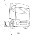
- Figure 1 represents a heavy-duty vehicle 2, which, in the example, is a truck.
- the truck 2 includes a front axle 4 and a rear axle 6.
- the truck is a 4 by 2 truck, i.e. a truck with four wheels in which torque is delivered to only two wheels.
- the invention is applicable to other truck configurations, such as 6 by 4 trucks and 6 by 2 trucks.
- the rear axle 6 is better represented on Fig. 2 .
- the wheels are not represented.
- rear axle 6 includes an axle housing 8 inside which a differential (not visible) is arranged.
- the differential includes an orifice for receiving one end of a propeller shaft 10.
- the axle 6 further includes two wheel brakes 12 provided each at one longitudinal end of the axle 6.
- Each wheel brake 12 is an air brake or, more formally, a compressed air brake system, which is a type of friction brake in which compressed air pressing on a piston is used to apply the pressure to the brake pad (not shown) needed to stop the vehicle 2.
- the vehicle 2 includes an air tank and a compressor (not represented).
- each wheel brake 12 is a drum brake that is applied by brake shoes (not shown) being pressed against a brake drum 16.
- drum brakes include cam brakes and wedge brakes.
- each wheel brake 12 includes a cam actuation mechanism, in which a brake cylinder 18, also known as an "air cylinder", converts the energy of compressed air to mechanical operation.
- a brake cylinder 18 also known as an "air cylinder”
- each wheel brake 12 has its own brake cylinder 18, which means that there are two brake cylinders 18 fitted on the axle.
- Each brake cylinder 18 consists of two chambers (not shown) separated by a rubber diaphragm (not shown either).
- a push rod 14 also known as “piston”
- This causes the push rod 14 to move out from the cylinder 18 and to push on a rotating lever 20 also known as “brake lever” or “brake arm”
- the rotating lever 20 transforms the force of the push rod 14 into a torque that is applied to a brake shaft 22. Therefore, brake lever 20 is designed for transmitting the movement of cylinder rod 14 to brake shaft 22.
- brake lever 20 is made of metal or an alloy.
- figures 2 and 3 show a traditional drum brake.
- the invention specifically concerns the brake lever 20 as represented on the figures 4 and following.
- the brake lever that is represented on figures 2 and 3 is a brake lever of prior art.
- the brake lever 20 according to the invention is represented on figures 4 and following.
- a cam (not shown), e.g. a S-shaped cam, is arranged at the end of the brake shaft 22. As the cam rotates, it forces two symmetrical brake pads (not shown) against the brake drum 16 until the pressure is released and the brake pads return to their resting position.
- the brake shoe carries the brake lining, which is riveted or glued to the shoe. When the brake is applied, the shoe moves and presses the lining against the inside of the drum 16. The friction between lining and drum provides the braking effort. Energy is dissipated as heat.
- brake lever 20 comprises a first portion 20a delimiting a hole 24 for fitting the brake shaft 22. Accordingly, hole 24 comprises a central axis X24 that is confounded with the axis of rotation of the brake shaft 22.
- the brake shaft 22 extends longitudinally parallel to the rotation axis of the wheels (in neutral configuration obviously, i.e. when steering angle is of 0°).
- brake lever 20 further comprises a second portion 20b, which is configured to be pivotally connected to the cylinder rod 14.
- the second portion 20b includes a circular bore 30 for receiving a pin (not shown) attached to one end of the push rod 14.
- Bore 30 defines a central axis X30 that represents the axis of rotation of the brake lever 20 relative to the push rod 14.
- Axes X24 and X30 are parallel one with the other.
- bore 30 is a through hole.
- brake lever 20 includes a mechanism (not shown) that enables to adjust the rest position of the shoes when the distance between the drum and shoes reaches a certain point. Precisely, the brake shoes are moved radially outwards so as to be closer to the drum.
- Such mechanism which is known as "slack adjuster"
- slack adjuster can be manual or automatic (self-adjusting) and is built into the brake lever 20 connecting the push rod 14 to the brake shaft 22.
- the slack adjuster is housed inside the first portion 20a of the brake lever 20.
- brake lever 20 and brake shaft 22 are coupled using a dog gear mechanism:
- the hole 24 is part of a crown wheel (that is partially visible on figure 4 ), which is itself part of the slack adjuster and the crown wheel comprises, on the inside, a succession of teeth that engage into complementary splines provided on the brake shaft 22. This enables to rigidly secure the crown wheel of the brake lever 20 in rotation with the brake shaft 22.
- a plane P1 is defined as the plane, perpendicular to the central axis X24, passing by a connection point A between the rotating lever 20 and the push rod 14 and.
- a plane P2 is defined as the plane, perpendicular to that of Figure 5 , extending between point A and a connection point B between brake lever 20 and brake shaft 22.
- a plane P3 is defined as the plane passing by point B and perpendicular to the central axis X24 of the hole 24.
- first and second portions 20a, 20b are end portions of the brake lever 20.
- Portion 20b is flat, which means that it extends parallel to plane P1.
- first portion 20a and the second portion 20b are offset from each other with respect to the central axis X24 of the hole 24.
- planes P1 and P3 are spaced one from the other by a distance (or "offset") d1.
- brake lever 20 is not straight, but includes angled parts.
- brake lever 20 further includes a central portion 20c extending between the first and second portions 20a, 20b.
- the central portion 20c extends obliquely with respect to the second portion 20b. This means that there is an angle ⁇ between the planes P1 and P2.
- the offset d1 ranges from 0 to 70 mm. In the example of the figures, the offset d1 is high, e.g. about 70 mm. Accordingly, significant lateral loads are induced on the brake shaft 22 during actuation of the brake, causing wear and tear on the brake shaft splines and accelerating the damage on the slack adjuster mechanism.
- the force F1 applied by the push rod 14 can be decomposed into a first force F2 corresponding to the projection of the force F1 into plane P2 and a second force F3 corresponding to the projection of the force F1 into a plane P4 corresponding to the plane of figure 5 , perpendicular to planes P1 and P3.
- Plane P4 includes axes X30 and X24.
- the brake shaft 20 exerts on brake lever 20 a force F4 that balances force F3.
- This force F4 known as "lateral load” can cause wear and tear on the brake shaft splines (not shown) and accelerate the damage on the slack adjuster mechanism.
- the brake lever 20 further includes a stiffening member 28 that extends along a direction L1 contained inside the plane P1 and that includes an orifice 32 for fitting the brake shaft 22.
- the stiffening member 28 extends from the second portion 20b, which means that it forms an extension of the second portion 20b.
- the stiffening member 28 extends from the central portion 20c. Accordingly, the stiffening member 28 is offset from the second portion 20b with respect to the central axis X24 of the hole 24. In other words, stiffening member 28 extends along a direction contained inside a plane P5 that is perpendicular to the central axis X24 of the hole and that is spaced from plane P3 by a distance (or "offset") d2 that is inferior to d1.
- orifice 32 is a through hole of circular shape.
- the orifice 32 is preferably coaxially aligned with the hole 24.
- the stiffening member 28 is not designed for transmitting any torque to the brake shaft 22:
- the diameter of the orifice 32 is large enough to fit the end of the brake shaft 22, with a radial clearance that allows the brake shaft 22 to rotate inside the orifice 32.
- the orifice 32 acts as a bearing that supports the rotation of the brake shaft 22. Accordingly, the stiffening member 28 acts as a support leg.
- the diameter of orifice 32 is inferior to that of hole 24. Therefore, in the example, the brake shaft 22 is a stepped shaft, provided with at least one radial shoulder (not shown) allowing to have a reduced outer diameter at the end.
- the stiffening member 28 extends perpendicular to the central axis X24 of hole 24, which means that direction L1 is a straight line.
- Figures 7 to 9 represent a second embodiment of a brake lever 20.
- the numeral references used herein are the same than that of the first embodiment.
- the stiffening member 28 extends in a curved manner. More precisely, the stiffening member 28 is in the form of a curl (or comma-shaped). The advantage of having this curved stiffening member 28 is that it can match with the shape of the axle housing 8.
- the direction L1 along which extends the stiffening member 28 is a curved line contained inside the plane P1.
- the orifice 32 delimited at the end of the stiffening member 28, which is of circular shape, has a diameter similar to that of the brake shaft 22, which means that there is no need to modify the brake shaft 22.
- orifice 32 is a through hole of circular shape.
- the orifice 32 is delimited inside a casing 40 extending parallel to axis X24 between the stiffening member 28 and portion 20a.
- casing 40 makes the junction between stiffening member 28 and portion 20a of brake lever 20.
- the casing 40 of cylindrical shape, is arranged around the end of the brake shaft 22. This enables to increase the robustness of the brake lever 20, to offer a better protection against dust and to provide a better axial support of the brake shaft 22.
- the disclosure further includes the following examples.
Landscapes
- Engineering & Computer Science (AREA)
- General Engineering & Computer Science (AREA)
- Mechanical Engineering (AREA)
- Braking Arrangements (AREA)
Abstract
Description
- The invention relates to a brake lever for a drum brake arrangement, said brake lever being designed for transmitting the movement of a cylinder rod to a brake shaft.
- The invention can be applied in heavy-duty vehicles, such as trucks, buses and construction equipment. This means that although the invention will be described with respect to a truck, the invention is not restricted to this particular vehicle, but may also be used in other vehicles such as buses, construction equipment, military vehicles and so on.
- Air brakes or, more formally, compressed air brake systems, are a type of friction brake for vehicles in which compressed air pressing on a piston is used to apply the pressure to the brake pad needed to stop the vehicle.
- Air brakes are typically used on heavy trucks and buses. On this type of vehicle, the brake system consists of a service brake, a parking brake, a control pedal and an air storage tank. For the parking brake, there is a disc or drum brake arrangement, which is designed to be held in the "applied" position by spring pressure. Air pressure must be produced to release these "spring brake" parking brakes. For the service brake (i.e. the one used while driving for slowing or stopping) to be applied, the brake pedal is pushed, routing the air under pressure to the brake chamber, causing the brake to be engaged. Most types of truck air brakes are drum brakes, though there is an increasing trend towards the use of disc brakes.
- A drum brake is a wheel brake that is applied by brake shoes being pressed against a brake drum. There are a number of different types of drum brakes, where the difference lies in the mechanism that transmits the braking force from the brake cylinder to the brake lining. In particular, drum brakes include cam brakes and wedge brakes.
- In a cam brake, the brake cylinder converts the energy of compressed air to mechanical operation. It consists of two chambers separated by a rubber diaphragm. When the brake pedal is depressed, air flows into the cylinder and pushes the diaphragm against a push rod. This causes the push rod to move out from the cylinder and to push on a rotating lever (also known as "brake lever" or "brake arm"). The rotating lever transforms the force of the push rod into a torque that is applied to a brake shaft. A cam, e.g. a S-shaped cam, is arranged at the end of the brake shaft. As the cam rotates, it forces two symmetrical brake pads against the brake drum until the pressure is released and the brake pads return to their resting position. The brake shoe carries the brake lining, which is riveted or glued to the shoe. When the brake is applied, the shoe moves and presses the lining against the inside of the drum. The friction between lining and drum provides the braking effort. Energy is dissipated as heat.
- As the brake linings wear, the shoes must travel a greater distance to reach the drum. Therefore, it is known to equip the cam brake arrangements with a mechanism that enables to adjust the rest position of the shoes when the distance between the drum and shoes reaches a certain point. Precisely, the brake shoes are moved radially outwards so as to be closer to the drum. Such mechanism, which is also known as "slack adjuster", can be manual or automatic (self-adjusting) and is built into the brake lever connecting the push rod to the brake shaft.
-
US 4, 596, 319 discloses an example of an automatic slack adjuster for vehicle brakes. - In order to overcome some packaging constraints in the vehicle architecture, the brake lever is not straight, but includes angled parts. This means that there is an angle between the line extending between the two connection points of the brake lever and the plane perpendicular to the axis of rotation of the brake shaft. The greater the offset, the greater the angle.
- The offset usually ranges from 0 to 70 mm. However, when the offset is high, e.g. about 70 mm, significant lateral loads are induced on the brake shaft during actuation of the brake, causing wear and tear on the brake shaft splines and accelerating the damage on the slack adjuster itself.
- An object of the invention is to provide a new brake lever design that allows better withstanding to lateral stress.
- The object is achieved by a brake lever according to claim 1.
- By the provision of a brake lever which comprises a stiffening member, the advantage is that the stiffening member absorbs at least a part of the lateral efforts to which the brake shaft is exposed in the connection area with the brake shaft.
- Further advantages and advantageous features of the invention are disclosed in the following description and in the
dependent claims 2 to 13. - The invention also concerns a drum brake according to
claim 14 and a heavy-duty vehicle according to claim 15. - With reference to the appended drawings, below follows a more detailed description of three embodiments of the invention cited as examples.
- In the drawings:
-
Fig. 1 is a perspective a view of a vehicle, typically a truck, comprising at least one drum brake provided with a brake lever of the invention; -
Fig. 2 is a perspective view of a vehicle axle, comprising two end wheel brakes, typically two drum brakes of prior art; -
Fig. 3 is a partial view along the arrow III infigure 2 ; -
Fig. 4 is a perspective view of a brake lever according to a first embodiment of the invention; -
Fig. 5 is a top view of the brake lever; -
Fig. 6 is a side view of the brake lever; -
Fig. 7 is a view similar toFig. 4 , representing a brake lever according to a second embodiment of the invention; -
Fig. 8 and 9 are side views of the brake lever ofFig. 7 ; and -
Fig. 10 to 12 represent views of a brake lever according to a third embodiment of the invention. -
Figure 1 represents a heavy-duty vehicle 2, which, in the example, is a truck. - The
truck 2 includes afront axle 4 and arear axle 6. In the example, the truck is a 4 by 2 truck, i.e. a truck with four wheels in which torque is delivered to only two wheels. Obviously, the invention is applicable to other truck configurations, such as 6 by 4 trucks and 6 by 2 trucks. - The
rear axle 6 is better represented onFig. 2 . For the clarity of the drawings, the wheels are not represented. - In known manner,
rear axle 6 includes anaxle housing 8 inside which a differential (not visible) is arranged. The differential includes an orifice for receiving one end of apropeller shaft 10. - The
axle 6 further includes twowheel brakes 12 provided each at one longitudinal end of theaxle 6. - Each
wheel brake 12 is an air brake or, more formally, a compressed air brake system, which is a type of friction brake in which compressed air pressing on a piston is used to apply the pressure to the brake pad (not shown) needed to stop thevehicle 2. In this respect, thevehicle 2 includes an air tank and a compressor (not represented). - In the example, each
wheel brake 12 is a drum brake that is applied by brake shoes (not shown) being pressed against abrake drum 16. There are a number of different types of drum brakes, where the difference lies in the mechanism that transmits the braking force from the brake cylinder to the brake lining. In particular, drum brakes include cam brakes and wedge brakes. - Typically, each
wheel brake 12 includes a cam actuation mechanism, in which abrake cylinder 18, also known as an "air cylinder", converts the energy of compressed air to mechanical operation. In the example, eachwheel brake 12 has itsown brake cylinder 18, which means that there are twobrake cylinders 18 fitted on the axle. - Each
brake cylinder 18 consists of two chambers (not shown) separated by a rubber diaphragm (not shown either). When the brake pedal is depressed, air flows into thecylinder 18 and pushes the diaphragm against a push rod 14 (also known as "piston"). This causes thepush rod 14 to move out from thecylinder 18 and to push on a rotating lever 20 (also known as "brake lever" or "brake arm"). The rotatinglever 20 transforms the force of thepush rod 14 into a torque that is applied to abrake shaft 22. Therefore,brake lever 20 is designed for transmitting the movement ofcylinder rod 14 to brakeshaft 22. - Preferably,
brake lever 20 is made of metal or an alloy. - To be clear,
figures 2 and 3 show a traditional drum brake. The invention specifically concerns thebrake lever 20 as represented on thefigures 4 and following. In other words, the brake lever that is represented onfigures 2 and 3 is a brake lever of prior art. Thebrake lever 20 according to the invention is represented onfigures 4 and following. - A cam (not shown), e.g. a S-shaped cam, is arranged at the end of the
brake shaft 22. As the cam rotates, it forces two symmetrical brake pads (not shown) against thebrake drum 16 until the pressure is released and the brake pads return to their resting position. The brake shoe carries the brake lining, which is riveted or glued to the shoe. When the brake is applied, the shoe moves and presses the lining against the inside of thedrum 16. The friction between lining and drum provides the braking effort. Energy is dissipated as heat. - In the example,
brake lever 20 comprises afirst portion 20a delimiting ahole 24 for fitting thebrake shaft 22. Accordingly,hole 24 comprises a central axis X24 that is confounded with the axis of rotation of thebrake shaft 22. - Basically, the
brake shaft 22 extends longitudinally parallel to the rotation axis of the wheels (in neutral configuration obviously, i.e. when steering angle is of 0°). - In the embodiment of the figures,
brake lever 20 further comprises asecond portion 20b, which is configured to be pivotally connected to thecylinder rod 14. In this respect, thesecond portion 20b includes acircular bore 30 for receiving a pin (not shown) attached to one end of thepush rod 14.Bore 30 defines a central axis X30 that represents the axis of rotation of thebrake lever 20 relative to thepush rod 14. Axes X24 and X30 are parallel one with the other. - In the example, bore 30 is a through hole.
- As the brake linings wear, the shoes must travel a greater distance to reach the
drum 16. Therefore,brake lever 20 includes a mechanism (not shown) that enables to adjust the rest position of the shoes when the distance between the drum and shoes reaches a certain point. Precisely, the brake shoes are moved radially outwards so as to be closer to the drum. Such mechanism, which is known as "slack adjuster", can be manual or automatic (self-adjusting) and is built into thebrake lever 20 connecting thepush rod 14 to thebrake shaft 22. - Typically, the slack adjuster is housed inside the
first portion 20a of thebrake lever 20. In known manner,brake lever 20 andbrake shaft 22 are coupled using a dog gear mechanism: Thehole 24 is part of a crown wheel (that is partially visible onfigure 4 ), which is itself part of the slack adjuster and the crown wheel comprises, on the inside, a succession of teeth that engage into complementary splines provided on thebrake shaft 22. This enables to rigidly secure the crown wheel of thebrake lever 20 in rotation with thebrake shaft 22. - A plane P1 is defined as the plane, perpendicular to the central axis X24, passing by a connection point A between the
rotating lever 20 and thepush rod 14 and. A plane P2 is defined as the plane, perpendicular to that ofFigure 5 , extending between point A and a connection point B betweenbrake lever 20 andbrake shaft 22. A plane P3 is defined as the plane passing by point B and perpendicular to the central axis X24 of thehole 24. - Preferably, the first and
second portions brake lever 20.Portion 20b is flat, which means that it extends parallel to plane P1. - In order to overcome some packaging constraints in the vehicle architecture, the
first portion 20a and thesecond portion 20b are offset from each other with respect to the central axis X24 of thehole 24. In other words, planes P1 and P3 are spaced one from the other by a distance (or "offset") d1. - In this respect, the
brake lever 20 is not straight, but includes angled parts. Precisely,brake lever 20 further includes acentral portion 20c extending between the first andsecond portions central portion 20c extends obliquely with respect to thesecond portion 20b. This means that there is an angle θ between the planes P1 and P2. The greater the offset d1, the greater the angle θ. Therefore, thefirst portion 20a ofbrake lever 20 is offset with respect to thesecond portion 20b. - The offset d1 ranges from 0 to 70 mm. In the example of the figures, the offset d1 is high, e.g. about 70 mm. Accordingly, significant lateral loads are induced on the
brake shaft 22 during actuation of the brake, causing wear and tear on the brake shaft splines and accelerating the damage on the slack adjuster mechanism. - More precisely, and referring to
figures 5 and6 , as an angle θ exists between planes P1 and P2, the force F1 applied by thepush rod 14 can be decomposed into a first force F2 corresponding to the projection of the force F1 into plane P2 and a second force F3 corresponding to the projection of the force F1 into a plane P4 corresponding to the plane offigure 5 , perpendicular to planes P1 and P3. Plane P4 includes axes X30 and X24. - As there is no displacement of the
brake lever 20 along axis X24, i.e. no degree of freedom in that direction, thebrake shaft 20 exerts onbrake lever 20 a force F4 that balances force F3. This force F4, known as "lateral load", can cause wear and tear on the brake shaft splines (not shown) and accelerate the damage on the slack adjuster mechanism. - In order to absorb that lateral effort F4, and to avoid premature wear of the
brake lever 20, thebrake lever 20 further includes a stiffeningmember 28 that extends along a direction L1 contained inside the plane P1 and that includes anorifice 32 for fitting thebrake shaft 22. - In the embodiment of
figures 1 to 9 , the stiffeningmember 28 extends from thesecond portion 20b, which means that it forms an extension of thesecond portion 20b. - In the alternative embodiment of
figures 10 to 12 , the stiffeningmember 28 extends from thecentral portion 20c. Accordingly, the stiffeningmember 28 is offset from thesecond portion 20b with respect to the central axis X24 of thehole 24. In other words, stiffeningmember 28 extends along a direction contained inside a plane P5 that is perpendicular to the central axis X24 of the hole and that is spaced from plane P3 by a distance (or "offset") d2 that is inferior to d1. - In the example,
orifice 32 is a through hole of circular shape. - Obviously, the
orifice 32 is preferably coaxially aligned with thehole 24. - The stiffening
member 28 is not designed for transmitting any torque to the brake shaft 22: The diameter of theorifice 32 is large enough to fit the end of thebrake shaft 22, with a radial clearance that allows thebrake shaft 22 to rotate inside theorifice 32. As a matter of fact, theorifice 32 acts as a bearing that supports the rotation of thebrake shaft 22. Accordingly, the stiffeningmember 28 acts as a support leg. - Basically, the diameter of
orifice 32 is inferior to that ofhole 24. Therefore, in the example, thebrake shaft 22 is a stepped shaft, provided with at least one radial shoulder (not shown) allowing to have a reduced outer diameter at the end. - In the example of
figures 4 to 6 , the stiffeningmember 28 extends perpendicular to the central axis X24 ofhole 24, which means that direction L1 is a straight line. -
Figures 7 to 9 represent a second embodiment of abrake lever 20. For the purpose of clarity, the numeral references used herein are the same than that of the first embodiment. - In this second embodiment, the stiffening
member 28 extends in a curved manner. More precisely, the stiffeningmember 28 is in the form of a curl (or comma-shaped). The advantage of having thiscurved stiffening member 28 is that it can match with the shape of theaxle housing 8. - In other words, the direction L1 along which extends the stiffening
member 28 is a curved line contained inside the plane P1. - In this example, the
orifice 32 delimited at the end of the stiffeningmember 28, which is of circular shape, has a diameter similar to that of thebrake shaft 22, which means that there is no need to modify thebrake shaft 22. - In this example,
orifice 32 is a through hole of circular shape. - Advantageously, the
orifice 32 is delimited inside acasing 40 extending parallel to axis X24 between the stiffeningmember 28 andportion 20a. In other words, casing 40 makes the junction between stiffeningmember 28 andportion 20a ofbrake lever 20. Thecasing 40, of cylindrical shape, is arranged around the end of thebrake shaft 22. This enables to increase the robustness of thebrake lever 20, to offer a better protection against dust and to provide a better axial support of thebrake shaft 22. - It is to be understood that the present invention is not limited to the embodiments described above and illustrated in the drawings; Rather, the skilled person will recognize that many changes and modifications may be made within the scope of the appended claims.
- The disclosure further includes the following examples.
- Example 1 : A brake lever (20) for a drum brake arrangement (12), said brake lever being designed for transmitting the movement of a cylinder rod (14) to a brake shaft (22), wherein the brake lever (20) comprises a first portion (20a) delimiting a hole (24) for fitting the brake shaft (22) and a second portion (20b), which is configured to be pivotally connected to the cylinder rod (14) and wherein the first portion and the second portion are offset from each other with respect to a central axis (X24) of the hole (24),
characterized in that the brake lever further includes a stiffening member (28) that extends along a direction (L1) contained inside a plane (P1) perpendicular to the central axis (X24) of the hole and that includes an orifice (32) for fitting the brake shaft (22). - Example 2: The brake lever according to Example 1, characterized in that the stiffening member (28) extends in a straight line perpendicular to the central axis of the hole. Example 3: The brake lever according to Example 1, characterized in that the stiffening member (28) extends in a curved manner.
- Example 4: The brake lever according to any previous Example, characterized in that the first and second portions (20a, 20b) are end portions of the brake lever (20). Example 5: The brake lever according to any previous Example, characterized in that the second portion (20b) includes a circular bore (30) for receiving a pin.
- Example 6: The brake lever according to any previous Example, characterized in that it further includes a central portion (20c) extending between the first and second portions (20a, 20b).
- Example 7: The brake lever according to previous Example, characterized in that the central portion (20c) extends obliquely with respect to the second portion (20b). Example 8: The brake lever according to Example 6 or 7, characterized in that the stiffening member (28) extends from the second portion (20b) or from the central portion (20c).
- Example 9: The brake lever according to any previous Example, characterized in that it includes an automatic or manual slack adjuster.
- Example 10: The brake lever according to any previous Example, characterized in that the offset (d1) between the first portion (20a) and the second potion (20b) is inferior or equal to 70 mm.
- Example 11: The brake lever according to any previous Example, characterized in that the orifice (32) and the hole (24) have the same diameter.
- Example 12: The brake lever according to any previous Example, characterized in that the orifice (32) is a through hole of circular shape.
- Example 13: The brake lever according to any previous Example, characterized in that the orifice (32) is delimited by a casing (40) extending axially between the stiffening member (28) and the first portion (20a).
- Example 14: A drum brake arrangement (12), comprising a brake cylinder (18) provided with a push rod (14), a brake shaft (22) and a brake lever (20) for transmitting the movement of the push rod (14) to the brake shaft, characterized in that the brake lever (20) is according to any previous Example.
- Example 15: A heavy-duty vehicle (2), such as a truck or a bus, comprising at least one drum brake arrangement (12) according to previous Example.
Claims (12)
- A brake lever (20) for a drum brake arrangement (12), said brake lever being designed for transmitting the movement of a cylinder rod (14) to a brake shaft (22), wherein the brake lever (20) comprises a first portion (20a) delimiting a hole (24) for fitting the brake shaft (22) and a second portion (20b), which is configured to be pivotally connected to the cylinder rod (14) and wherein the first portion and the second portion are offset from each other with respect to a central axis (X24) of the hole (24),characterized in that the brake lever further includes a stiffening member (28) that extends along a direction (L1) contained inside a plane (P1) perpendicular to the central axis (X24) of the hole and that includes an orifice (32) for fitting the brake shaft (22),in that the brake lever (20) further includes a central portion (20c) extending between the first and second portions (20a, 20b),in that the central portion (20c) extends obliquely with respect to the second portion (20b),in that the stiffening member (28) extends from the central portion (20c),and in that the stiffening member (28) is offset from the second portion (20b) with respect to the central axis (X24) of the hole (24).
- The brake lever according to claim 1, characterized in that the stiffening member (28) extends along a direction contained inside a plane (P5) that is perpendicular to the central axis (X24) of the hole (24) and that is spaced from a plane (P3), defined as the plane passing by a connection point (B) between brake lever (20) and brake shaft (22) and perpendicular to the central axis (X24) of the hole (24), by a distance (d2) that is inferior to a distance (d1) between, on the one hand, the plane (P1) perpendicular to the central axis (X24) of the hole and that includes an orifice (32) for fitting the brake shaft (22) and, on the other hand, the plane (P3) passing by a connection point (B) between brake lever (20) and brake shaft (22) and perpendicular to the central axis (X24) of the hole (24).
- The brake lever according to claim 1 or 2, characterized in that the stiffening member (28) extends in a straight line perpendicular to the central axis of the hole.
- The brake lever according to any previous claim, characterized in that the first and second portions (20a, 20b) are end portions of the brake lever (20).
- The brake lever according to any previous claim, characterized in that the second portion (20b) includes a circular bore (30) for receiving a pin.
- The brake lever according to any previous claim, characterized in that it includes an automatic or manual slack adjuster.
- The brake lever according to any previous claim, characterized in that the offset (d1) between the first portion (20a) and the second potion (20b) is inferior or equal to 70 mm.
- The brake lever according to any previous claim, characterized in that the orifice (32) and the hole (24) have the same diameter.
- The brake lever according to any previous claim, characterized in that the orifice (32) is a through hole of circular shape.
- The brake lever according to any previous claim, characterized in that the orifice (32) is delimited by a casing (40) extending axially between the stiffening member (28) and the first portion (20a).
- A drum brake arrangement (12), comprising a brake cylinder (18) provided with a push rod (14), a brake shaft (22) and a brake lever (20) for transmitting the movement of the push rod (14) to the brake shaft, characterized in that the brake lever (20) is according to any previous claim.
- A heavy-duty vehicle (2), such as a truck or a bus, comprising at least one drum brake arrangement (12) according to previous claim.
Priority Applications (1)
| Application Number | Priority Date | Filing Date | Title |
|---|---|---|---|
| EP24220946.8A EP4502414A3 (en) | 2020-10-07 | 2020-10-07 | High offset slack adjuster with additional low offset arm to reduce lateral loads |
Applications Claiming Priority (2)
| Application Number | Priority Date | Filing Date | Title |
|---|---|---|---|
| EP20200510.4A EP3981998B1 (en) | 2020-10-07 | 2020-10-07 | High offset slack adjuster with additional low offset arm to reduce lateral loads |
| EP24220946.8A EP4502414A3 (en) | 2020-10-07 | 2020-10-07 | High offset slack adjuster with additional low offset arm to reduce lateral loads |
Related Parent Applications (2)
| Application Number | Title | Priority Date | Filing Date |
|---|---|---|---|
| EP20200510.4A Division EP3981998B1 (en) | 2020-10-07 | 2020-10-07 | High offset slack adjuster with additional low offset arm to reduce lateral loads |
| EP20200510.4A Division-Into EP3981998B1 (en) | 2020-10-07 | 2020-10-07 | High offset slack adjuster with additional low offset arm to reduce lateral loads |
Publications (2)
| Publication Number | Publication Date |
|---|---|
| EP4502414A2 true EP4502414A2 (en) | 2025-02-05 |
| EP4502414A3 EP4502414A3 (en) | 2025-03-12 |
Family
ID=72801350
Family Applications (2)
| Application Number | Title | Priority Date | Filing Date |
|---|---|---|---|
| EP24220946.8A Pending EP4502414A3 (en) | 2020-10-07 | 2020-10-07 | High offset slack adjuster with additional low offset arm to reduce lateral loads |
| EP20200510.4A Active EP3981998B1 (en) | 2020-10-07 | 2020-10-07 | High offset slack adjuster with additional low offset arm to reduce lateral loads |
Family Applications After (1)
| Application Number | Title | Priority Date | Filing Date |
|---|---|---|---|
| EP20200510.4A Active EP3981998B1 (en) | 2020-10-07 | 2020-10-07 | High offset slack adjuster with additional low offset arm to reduce lateral loads |
Country Status (3)
| Country | Link |
|---|---|
| US (2) | US11892047B2 (en) |
| EP (2) | EP4502414A3 (en) |
| CN (1) | CN114294356A (en) |
Citations (1)
| Publication number | Priority date | Publication date | Assignee | Title |
|---|---|---|---|---|
| US4596319A (en) | 1983-11-14 | 1986-06-24 | Cumming James C | Automatic slack adjuster for vehicle brakes |
Family Cites Families (19)
| Publication number | Priority date | Publication date | Assignee | Title |
|---|---|---|---|---|
| US2385621A (en) * | 1943-07-27 | 1945-09-25 | Shively | Brake operating mechanism |
| FR1330177A (en) * | 1962-04-25 | 1963-06-21 | Bendix Corp | Drum brake improvements |
| US4580665A (en) * | 1979-05-18 | 1986-04-08 | Rockwell International Corporation | Quick connect brake coupling |
| US4256208A (en) * | 1979-05-29 | 1981-03-17 | Eaton Corporation | Slack adjuster |
| ZA802147B (en) * | 1979-05-29 | 1981-04-29 | Eaton Corp | Improved slack adjuster |
| DE4017949A1 (en) * | 1990-06-05 | 1991-12-12 | Wabco Westinghouse Fahrzeug | DEVICE FOR AUTOMATIC REALIZATION OF A BRAKE, IN PARTICULAR VEHICLE BRAKE |
| SE504466C2 (en) * | 1995-06-08 | 1997-02-17 | Haldex Ab | Wear indication device for brake pads |
| US7198138B2 (en) * | 2004-06-14 | 2007-04-03 | Ang Automotive India Private Limited | Automatic slack adjuster assembly for vehicle braking system |
| US8820490B2 (en) * | 2012-03-16 | 2014-09-02 | Arvinmeritor Technology, Llc | Manual adjuster for automatic slack adjuster |
| US9605724B2 (en) * | 2014-06-26 | 2017-03-28 | Arvinmeritor Technology, Llc | Brake assembly having a camshaft sensor module |
| USD770344S1 (en) * | 2015-06-16 | 2016-11-01 | Haldex Brake Products Ab | Brake adjuster |
| US9574626B1 (en) * | 2015-07-28 | 2017-02-21 | Bendix Spicer Foundation Brake Llc | Rigid bracket assembly for mounting a brake assembly and brake actuator |
| DE102015010348A1 (en) * | 2015-08-06 | 2017-02-09 | Man Truck & Bus Ag | Device for fastening a wear sensor to a brake lever of a vehicle brake |
| RU178189U1 (en) * | 2017-03-20 | 2018-03-26 | Общество с ограниченной ответственностью "Ар Си Эр" | AUTOMATIC BRAKE LEVER |
| CN206816718U (en) * | 2017-05-25 | 2017-12-29 | 焦作金箍制动器股份有限公司 | A kind of one-piece brakes lever and the brake using the lever |
| US11293506B2 (en) * | 2017-05-31 | 2022-04-05 | Madras Engineering Industries Private Limited | Automatic slack adjuster |
| US11209062B2 (en) * | 2019-05-15 | 2021-12-28 | Bendix Commercial Vehicle Systems Llc | Automatic slack adjuster |
| CN210344113U (en) * | 2019-07-19 | 2020-04-17 | 绍兴铁安汽配制造有限公司 | A lightweight brake clearance automatic adjusting arm and braking system |
| US11655869B2 (en) * | 2020-07-10 | 2023-05-23 | Haldex Brake Products Corporation | Brake adjuster with brake stroke indicator |
-
2020
- 2020-10-07 EP EP24220946.8A patent/EP4502414A3/en active Pending
- 2020-10-07 EP EP20200510.4A patent/EP3981998B1/en active Active
-
2021
- 2021-09-28 CN CN202111143304.XA patent/CN114294356A/en active Pending
- 2021-10-06 US US17/450,111 patent/US11892047B2/en active Active
-
2023
- 2023-12-21 US US18/392,717 patent/US12129899B2/en active Active
Patent Citations (1)
| Publication number | Priority date | Publication date | Assignee | Title |
|---|---|---|---|---|
| US4596319A (en) | 1983-11-14 | 1986-06-24 | Cumming James C | Automatic slack adjuster for vehicle brakes |
Also Published As
| Publication number | Publication date |
|---|---|
| EP3981998B1 (en) | 2025-01-22 |
| CN114294356A (en) | 2022-04-08 |
| EP3981998A1 (en) | 2022-04-13 |
| US11892047B2 (en) | 2024-02-06 |
| US12129899B2 (en) | 2024-10-29 |
| US20240151285A1 (en) | 2024-05-09 |
| EP3981998C0 (en) | 2025-01-22 |
| EP4502414A3 (en) | 2025-03-12 |
| US20220106993A1 (en) | 2022-04-07 |
Similar Documents
| Publication | Publication Date | Title |
|---|---|---|
| US8011482B2 (en) | Electric actuator unit for a vehicle brake assembly | |
| US6799664B1 (en) | Drum brake assembly | |
| US8556045B2 (en) | Drum-in-hat disc brake assembly | |
| CN108884889B (en) | Shaft nut assembly with multiple stop cams | |
| US8056684B2 (en) | Vehicle drum-in-hat disc brake assembly and method for producing same | |
| US9777782B2 (en) | Shared anchor bracket for a disc brake assembly having separate service and parking brake assemblies | |
| US20060289253A1 (en) | Monoblock caliper housing for a disc brake assembly | |
| US5630486A (en) | Mechanical actuation device for drum brake | |
| US4030576A (en) | Disc brake assembly including a self-contained actuator with wear take-up and anti-drag device | |
| US6044938A (en) | Dual-mode drum brake having parking lever pivotable about an axis perpendicular to backing plate | |
| US6851524B2 (en) | Disc brake for motor vehicles | |
| JPS63140131A (en) | Disk brake | |
| CN113195919B (en) | wheel brake device | |
| US12129899B2 (en) | Brake lever for a drum brake arrangement, said brake lever being designed for transmitting the movement of a cylinder rod to a brake shaft | |
| US2873005A (en) | Disc brake for vehicles | |
| US3557912A (en) | Duo-servo drum brake and mechanical actuating means therefor | |
| US7490702B1 (en) | Parking and emergency brake actuator for a drum-in-hat disc brake assembly | |
| US20240123962A1 (en) | Apparatus for drum brake assembly | |
| US12352325B2 (en) | Drum brake assembly | |
| EP4219976A1 (en) | Park brake caliper with inverted lever configuration | |
| US20250003461A1 (en) | Braking system with balanced actuation | |
| EP1217244B1 (en) | Drum brake device with parking brake actuator, | |
| JPS628440Y2 (en) | ||
| KR100243607B1 (en) | Dual braking system of vehicle |
Legal Events
| Date | Code | Title | Description |
|---|---|---|---|
| PUAI | Public reference made under article 153(3) epc to a published international application that has entered the european phase |
Free format text: ORIGINAL CODE: 0009012 |
|
| STAA | Information on the status of an ep patent application or granted ep patent |
Free format text: STATUS: THE APPLICATION HAS BEEN PUBLISHED |
|
| REG | Reference to a national code |
Ref country code: DE Ref legal event code: R079 Free format text: PREVIOUS MAIN CLASS: F16D0065600000 Ipc: F16D0051220000 |
|
| AC | Divisional application: reference to earlier application |
Ref document number: 3981998 Country of ref document: EP Kind code of ref document: P |
|
| AK | Designated contracting states |
Kind code of ref document: A2 Designated state(s): AL AT BE BG CH CY CZ DE DK EE ES FI FR GB GR HR HU IE IS IT LI LT LU LV MC MK MT NL NO PL PT RO RS SE SI SK SM TR |
|
| PUAL | Search report despatched |
Free format text: ORIGINAL CODE: 0009013 |
|
| AK | Designated contracting states |
Kind code of ref document: A3 Designated state(s): AL AT BE BG CH CY CZ DE DK EE ES FI FR GB GR HR HU IE IS IT LI LT LU LV MC MK MT NL NO PL PT RO RS SE SI SK SM TR |
|
| RIC1 | Information provided on ipc code assigned before grant |
Ipc: F16D 65/60 20060101ALI20250204BHEP Ipc: F16D 51/22 20060101AFI20250204BHEP |
|
| STAA | Information on the status of an ep patent application or granted ep patent |
Free format text: STATUS: REQUEST FOR EXAMINATION WAS MADE |
|
| 17P | Request for examination filed |
Effective date: 20250910 |
|
| STAA | Information on the status of an ep patent application or granted ep patent |
Free format text: STATUS: EXAMINATION IS IN PROGRESS |
|
| 17Q | First examination report despatched |
Effective date: 20260319 |