EP4502394A1 - Bell mouth and fan unit - Google Patents
Bell mouth and fan unit Download PDFInfo
- Publication number
- EP4502394A1 EP4502394A1 EP23780652.6A EP23780652A EP4502394A1 EP 4502394 A1 EP4502394 A1 EP 4502394A1 EP 23780652 A EP23780652 A EP 23780652A EP 4502394 A1 EP4502394 A1 EP 4502394A1
- Authority
- EP
- European Patent Office
- Prior art keywords
- bell mouth
- circumferential wall
- changing component
- pressure changing
- component permeable
- Prior art date
- Legal status (The legal status is an assumption and is not a legal conclusion. Google has not performed a legal analysis and makes no representation as to the accuracy of the status listed.)
- Pending
Links
Images

Classifications
-
- F—MECHANICAL ENGINEERING; LIGHTING; HEATING; WEAPONS; BLASTING
- F04—POSITIVE - DISPLACEMENT MACHINES FOR LIQUIDS; PUMPS FOR LIQUIDS OR ELASTIC FLUIDS
- F04D—NON-POSITIVE-DISPLACEMENT PUMPS
- F04D29/00—Details, component parts, or accessories
- F04D29/40—Casings; Connections of working fluid
- F04D29/52—Casings; Connections of working fluid for axial pumps
- F04D29/522—Casings; Connections of working fluid for axial pumps especially adapted for elastic fluid pumps
- F04D29/526—Details of the casing section radially opposing blade tips
-
- F—MECHANICAL ENGINEERING; LIGHTING; HEATING; WEAPONS; BLASTING
- F04—POSITIVE - DISPLACEMENT MACHINES FOR LIQUIDS; PUMPS FOR LIQUIDS OR ELASTIC FLUIDS
- F04D—NON-POSITIVE-DISPLACEMENT PUMPS
- F04D29/00—Details, component parts, or accessories
- F04D29/66—Combating cavitation, whirls, noise, vibration or the like; Balancing
- F04D29/661—Combating cavitation, whirls, noise, vibration or the like; Balancing especially adapted for elastic fluid pumps
- F04D29/667—Combating cavitation, whirls, noise, vibration or the like; Balancing especially adapted for elastic fluid pumps by influencing the flow pattern, e.g. suppression of turbulence
-
- F—MECHANICAL ENGINEERING; LIGHTING; HEATING; WEAPONS; BLASTING
- F04—POSITIVE - DISPLACEMENT MACHINES FOR LIQUIDS; PUMPS FOR LIQUIDS OR ELASTIC FLUIDS
- F04D—NON-POSITIVE-DISPLACEMENT PUMPS
- F04D19/00—Axial-flow pumps
- F04D19/002—Axial flow fans
-
- F—MECHANICAL ENGINEERING; LIGHTING; HEATING; WEAPONS; BLASTING
- F04—POSITIVE - DISPLACEMENT MACHINES FOR LIQUIDS; PUMPS FOR LIQUIDS OR ELASTIC FLUIDS
- F04D—NON-POSITIVE-DISPLACEMENT PUMPS
- F04D29/00—Details, component parts, or accessories
- F04D29/40—Casings; Connections of working fluid
- F04D29/52—Casings; Connections of working fluid for axial pumps
- F04D29/54—Fluid-guiding means, e.g. diffusers
- F04D29/541—Specially adapted for elastic fluid pumps
-
- F—MECHANICAL ENGINEERING; LIGHTING; HEATING; WEAPONS; BLASTING
- F04—POSITIVE - DISPLACEMENT MACHINES FOR LIQUIDS; PUMPS FOR LIQUIDS OR ELASTIC FLUIDS
- F04D—NON-POSITIVE-DISPLACEMENT PUMPS
- F04D29/00—Details, component parts, or accessories
- F04D29/66—Combating cavitation, whirls, noise, vibration or the like; Balancing
- F04D29/661—Combating cavitation, whirls, noise, vibration or the like; Balancing especially adapted for elastic fluid pumps
- F04D29/663—Sound attenuation
- F04D29/664—Sound attenuation by means of sound absorbing material
-
- F—MECHANICAL ENGINEERING; LIGHTING; HEATING; WEAPONS; BLASTING
- F04—POSITIVE - DISPLACEMENT MACHINES FOR LIQUIDS; PUMPS FOR LIQUIDS OR ELASTIC FLUIDS
- F04D—NON-POSITIVE-DISPLACEMENT PUMPS
- F04D29/00—Details, component parts, or accessories
- F04D29/66—Combating cavitation, whirls, noise, vibration or the like; Balancing
- F04D29/68—Combating cavitation, whirls, noise, vibration or the like; Balancing by influencing boundary layers
- F04D29/681—Combating cavitation, whirls, noise, vibration or the like; Balancing by influencing boundary layers especially adapted for elastic fluid pumps
- F04D29/685—Inducing localised fluid recirculation in the stator-rotor interface
-
- F—MECHANICAL ENGINEERING; LIGHTING; HEATING; WEAPONS; BLASTING
- F24—HEATING; RANGES; VENTILATING
- F24F—AIR-CONDITIONING; AIR-HUMIDIFICATION; VENTILATION; USE OF AIR CURRENTS FOR SCREENING
- F24F1/00—Room units for air-conditioning, e.g. separate or self-contained units or units receiving primary air from a central station
- F24F1/06—Separate outdoor units, e.g. outdoor unit to be linked to a separate room comprising a compressor and a heat exchanger
- F24F1/38—Fan details of outdoor units, e.g. bell-mouth shaped inlets or fan mountings
-
- F—MECHANICAL ENGINEERING; LIGHTING; HEATING; WEAPONS; BLASTING
- F05—INDEXING SCHEMES RELATING TO ENGINES OR PUMPS IN VARIOUS SUBCLASSES OF CLASSES F01-F04
- F05D—INDEXING SCHEME FOR ASPECTS RELATING TO NON-POSITIVE-DISPLACEMENT MACHINES OR ENGINES, GAS-TURBINES OR JET-PROPULSION PLANTS
- F05D2250/00—Geometry
- F05D2250/50—Inlet or outlet
- F05D2250/51—Inlet
-
- F—MECHANICAL ENGINEERING; LIGHTING; HEATING; WEAPONS; BLASTING
- F05—INDEXING SCHEMES RELATING TO ENGINES OR PUMPS IN VARIOUS SUBCLASSES OF CLASSES F01-F04
- F05D—INDEXING SCHEME FOR ASPECTS RELATING TO NON-POSITIVE-DISPLACEMENT MACHINES OR ENGINES, GAS-TURBINES OR JET-PROPULSION PLANTS
- F05D2250/00—Geometry
- F05D2250/60—Structure; Surface texture
-
- F—MECHANICAL ENGINEERING; LIGHTING; HEATING; WEAPONS; BLASTING
- F05—INDEXING SCHEMES RELATING TO ENGINES OR PUMPS IN VARIOUS SUBCLASSES OF CLASSES F01-F04
- F05D—INDEXING SCHEME FOR ASPECTS RELATING TO NON-POSITIVE-DISPLACEMENT MACHINES OR ENGINES, GAS-TURBINES OR JET-PROPULSION PLANTS
- F05D2300/00—Materials; Properties thereof
- F05D2300/50—Intrinsic material properties or characteristics
- F05D2300/514—Porosity
-
- F—MECHANICAL ENGINEERING; LIGHTING; HEATING; WEAPONS; BLASTING
- F05—INDEXING SCHEMES RELATING TO ENGINES OR PUMPS IN VARIOUS SUBCLASSES OF CLASSES F01-F04
- F05D—INDEXING SCHEME FOR ASPECTS RELATING TO NON-POSITIVE-DISPLACEMENT MACHINES OR ENGINES, GAS-TURBINES OR JET-PROPULSION PLANTS
- F05D2300/00—Materials; Properties thereof
- F05D2300/60—Properties or characteristics given to material by treatment or manufacturing
- F05D2300/612—Foam
Definitions
- the present disclosure relates to a bell mouth and a fan unit.
- Patent Literature 1 describes a known technique related to a fan shroud of an axial fan.
- Patent Literature 1 describes that the fan shroud is entirely or partly made of a through-pore material such as plastic or sintered aluminum alloy.
- a through-pore material such as plastic or sintered aluminum alloy.
- Patent Literature 1 Microfilm of Japanese Utility Model Application No. 04-68593 ( Japanese Laid-Open Utility Model Application No 06-25597 )
- the pressure changing component permeable portions include pores connecting the opposite sides of the circumferential wall in the thickness direction.
- the pores have an average pore diameter of 1000 ⁇ m or less.
- this structure allows the air in the vicinity of the circumferential wall to pass through the pressure changing component permeable portions, and excessive air does not pass through the pressure changing component permeable portions. This reduces loss in the air that passes through the axial fan.
- This structure ensures that air passes through the pressure changing component permeable portions over a flow path length.
- a function for allowing for the permeable of the air in the vicinity of the circumferential wall through the pressure changing component permeable portions and a function for limiting the permeable of excessive air through the pressure changing component permeable portions are both obtained.
- the fan unit 10 includes a case 20, an axial fan 30, and a bell mouth 40.
- the case 20 includes a bottom wall 21, having the form of a rectangular plate, and side walls 22, each extending from the sides of the bottom wall 21 in the thickness direction of the bottom wall 21.
- the case 20 also includes a top wall 23 on the ends of the side walls 22 opposite to the bottom wall 21.
- the top wall 23 includes a circular opening 23a.
- a netted outlet grille 24 is attached to the opening 23a in the top wall 23.
- An axial fan motor 25 is attached to the bottom wall 21.
- the axial fan 30 and the bell mouth 40 are accommodated in the case 20.
- the axial fan 30 includes a rotary shaft 31 and three blades 32 connected to the rotary shaft 31.
- the axial fan 30 is accommodated in the case 20 in a state in which the rotary shaft 31 is connected to the axial fan motor 25.
- the bell mouth 40 is accommodated in the case and attached to the edge of the opening 23a in the top wall 23.
- a bell mouth 40 will now be described with reference to Figs. 1 and 2 .
- the outlet portion 41a is located at the end of the bell mouth 40 located at one side of the bell mouth 40 in a direction parallel to the axis D of the bell mouth 40.
- the outlet portion 41a is curved so that the inner diameter decreases toward the end at the other side of the bell mouth 40 in the direction parallel to the axis D of the bell mouth 40.
- the tubular portion 41b extends continuously from the end of the outlet portion 41a at the other side of the outlet portion 41a toward the other side of the bell mouth 40.
- the inner diameter of the tubular portion 41b is fixed.
- the axis of the tubular portion 41b coincides with the axis D of the bell mouth 40.
- the inlet portion 41c extends continuously from the end of the tubular portion 41b at the other side.
- the inlet portion 41c is curved so that the inner diameter increases from the end of the tubular portion 41b at the other side of the tubular portion 41b toward the other side of the bell mouth 40.
- the thickness of the circumferential wall 41 is not particularly limited.
- the thickness is preferably 1 mm or greater, and more preferably, 2 mm or greater. Further, the thickness is preferably 10 mm or less, and more preferably, 5 mm or less.
- the material of the circumferential wall 41 is not particularly limited, and a known material of the bell mouth 40 may be used.
- a known material of the bell mouth 40 include plastic, ceramic, metal, and the like.
- resin is preferred since the weight can be reduced while maintaining strength.
- a predetermined gap L1 is provided parallel to the axis D of the bell mouth 40 between the inlet portion 41c of the bell mouth 40 and the bottom wall 21 of the case 20.
- the fan unit 10 includes open space extending between the outer circumference of the bell mouth 40 and the side walls 22 of the case 20.
- the open space functions as an air layer S.
- the air layer S is not particularly limited in size.
- a maximum distance L2 from the side wall 22 of the case 20 to the circumferential wall 41 is preferably 1 cm or greater, and more preferably, 3 cm or greater.
- the maximum distance L2 from the side wall 22 of the case 20 to the circumferential wall 41 indicates the distance from the side wall 22 of the case 20 to the tubular portion 41b of the bell mouth 40.
- the pressure changing component permeable portion 50 will now be described with reference to Fig. 2 .
- the pressure changing component permeable portion 50 is formed by a porous body.
- the porous body extends through the circumferential wall 41 in the thickness direction.
- the porous body includes open pores connected to the outside.
- the open pores connect the opposite sides of the circumferential wall 41 in the thickness direction.
- the average pore diameter of the open pores is not particularly limited. However, the average pore diameter is preferably 1000 ⁇ m or less, and more preferably, 700 ⁇ m or less.
- the method for measuring the average pore diameter is not particularly limited.
- the average pore diameter can be measured through, for example, a gas adsorption method also referred to as a BET method.
- the material of the pressure changing component permeable portion 50 is not particularly limited, and the material of a known porous body may be used.
- the known porous body material include plastic, ceramic, metal, and the like. Resin foam may be used as the plastic.
- a porous sintered body may be used as the ceramic or the metal. Further, a netted body also referred to as a mesh can be used as the metal. In particular, the porous sintered body is preferred because the average pore diameter can be readily adjusted.
- the separated distance L3 of the circumferential wall 41 of the bell mouth 40 from the axial fan 30 is minimal at the tubular portion 41b.
- the separated distance L3 from the axial fan 30 indicates the distance between the blades 32 of the axial fan 30 and the circumferential wall 41 of the bell mouth 40 in a direction orthogonal to the axial direction of the axial fan 30.
- the pressure changing component permeable portions 50 are arranged in the tubular portion 41b of the bell mouth 40.
- the pressure changing component permeable portions 50 are provided in the circumferential wall 41 at a location where the separated distance L3 from the axial fan 30 is minimal.
- the axial direction of the axial fan 30 corresponds to the direction in which the axis D of the bell mouth 40 extends.
- the arrangement of the pressure changing component permeable portions 50 in the circumferential wall 41 of the bell mouth 40 is not particularly limited.
- the pressure changing component permeable portions 50 are formed having predetermined shapes.
- the bell mouth 40 is formed with openings in the circumferential wall 41 for fitting the pressure changing component permeable portions 50. Then, the pressure changing component permeable portions 50 are fitted into the openings of the circumferential wall 41 of the bell mouth 40. This arranges the pressure changing component permeable portions 50 in the circumferential wall 41 of the bell mouth 40.
- the pressure changing component permeable portions 50 may be bonded to the circumferential wall 41 of the bell mouth 40 with a known adhesive.
- Fig. 3 shows the magnitude of the airflow noise with respect to the airflow rate at a bell mouth surface. As shown in Fig. 3 , in the bell mouth 40 of Example 1, the airflow noise was reduced in all of the measured airflow rate ranges.
- Fig. 4 is a graph illustrating the comparison result of the characteristics of Example 1 and the characteristics of Comparative Example 1.
- Fig. 4 shows the magnitude of the airflow noise with respect to frequency.
- the peaks of a sound pressure level are caused by NZ noise, and parts other than the peaks are caused by wind noise at the surface of the bell mouth.
- the bell mouth 40 of the present embodiment includes the pressure changing component permeable portions 50 in the circumferential wall 41 at a location where the separated distance L3 from the axial fan 30 is minimal.
- the air readily passes through the pressure changing component permeable portions 50.
- the air can be released quickly through the pressure changing component permeable portions 50. This limits pressure changes in the vicinity of the circumferential wall 41, thereby mitigating surface vortices generated at the circumferential wall 41.
- the bell mouth 40 and the fan unit 10 of the present disclosure may be in the form of, for example, the modifications described below and a combination of at least two modifications that do not contradict each other.
- the pressure changing component permeable portion 50 may be arranged over the entire circumferential wall 41 of the bell mouth 40. Further, the circumferential wall 41 of the bell mouth 40 may be entirely formed by the pressure changing component permeable portion 50.
Landscapes
- Engineering & Computer Science (AREA)
- Mechanical Engineering (AREA)
- General Engineering & Computer Science (AREA)
- Chemical & Material Sciences (AREA)
- Combustion & Propulsion (AREA)
- Structures Of Non-Positive Displacement Pumps (AREA)
Abstract
Description
- The present disclosure relates to a bell mouth and a fan unit.
-
Patent Literature 1 describes a known technique related to a fan shroud of an axial fan.Patent Literature 1 describes that the fan shroud is entirely or partly made of a through-pore material such as plastic or sintered aluminum alloy. When the blades of the axial fan approach the fan shroud, the pressure of the flowing air changes in a sudden manner and produces impulsive noise that is absorbed by the through-pore material. This reduces NZ noise, which is blade pitch noise. - Patent Literature 1: Microfilm of
Japanese Utility Model Application No. 04-68593 Japanese Laid-Open Utility Model Application No 06-25597 - In addition to the NZ noise, it is desired that the bell mouth of the axial fan reduces wind noise generated at the surface of the bell mouth.
- A bell mouth that solves the above problem includes a circumferential wall and pressure changing component permeable portions in the circumferential wall at a location where a separated distance from an axial fan is minimal.
- With this structure, when the pressure changes in the air passing by the axial fan, the air in the vicinity of the circumferential wall readily passes through the pressure changing component permeable portions. Thus, the change in pressure is reduced. This mitigates surface vortices generated on the circumferential wall and suitably reduces wind noise caused by the surface vortices.
- In the above bell mouth, the pressure changing component permeable portions include pores connecting the opposite sides of the circumferential wall in the thickness direction. The pores have an average pore diameter of 1000 µm or less.
- When the pressure changes, this structure allows the air in the vicinity of the circumferential wall to pass through the pressure changing component permeable portions, and excessive air does not pass through the pressure changing component permeable portions. This reduces loss in the air that passes through the axial fan.
- In the above bell mouth, the pressure changing component permeable portions include pores connecting the opposite sides of the circumferential wall in the thickness direction. The pores have an average pore diameter of 700 µm or less.
- This structure allows the air in the vicinity of the circumferential wall to pass through the pressure changing component permeable portions, and further reduces loss in the air that passes through the axial fan.
- In the above bell mouth, the pressure changing component permeable portions are arranged at intervals in the circumferential direction of the circumferential wall.
- This structure allows for the arrangement of the pressure changing component permeable portions, while maintaining the strength of the bell mouth in a preferred manner.
- In the above bell mouth, the thickness of the circumferential wall is 1 mm or greater.
- This structure ensures that air passes through the pressure changing component permeable portions over a flow path length. Thus, a function for allowing for the permeable of the air in the vicinity of the circumferential wall through the pressure changing component permeable portions and a function for limiting the permeable of excessive air through the pressure changing component permeable portions are both obtained.
- In the above bell mouth, the thickness of the circumferential wall is 10 mm or less.
- With this structure, the thickness of the circumferential wall is relatively thin. Thus, the cost for manufacturing the bell mouth is reduced.
- A fan unit that solves the above problem includes the axial fan, the bell mouth, and a case, which accommodates the axial fan and the bell mouth. Further, in the fan unit, an air layer extends between the circumferential wall of the bell mouth and the case.
- With this structure, air that has passed through the pressure changing component permeable portions is released to the air layer. This readily reduces pressure changes in the pressure changing component permeable portions.
-
-
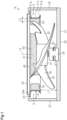
Fig. 1 is a partial cross-sectional view of a fan unit. -
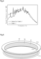
Fig. 2 is a perspective view of a bell mouth. -
Fig. 3 is a graph showing the comparison result of the characteristics of Example 1 and the characteristics of Comparative Example 1. -
Fig. 4 is a graph showing the comparison result of the characteristics of Example 1 and the characteristics of Comparative Example 1. -
Fig. 5 is a perspective view of a bell mouth in a modified example. - A
fan unit 10 will now be described with reference toFig. 1 . - As shown in
Fig. 1 , thefan unit 10 includes acase 20, anaxial fan 30, and abell mouth 40. Thecase 20 includes abottom wall 21, having the form of a rectangular plate, andside walls 22, each extending from the sides of thebottom wall 21 in the thickness direction of thebottom wall 21. Thecase 20 also includes atop wall 23 on the ends of theside walls 22 opposite to thebottom wall 21. Thetop wall 23 includes acircular opening 23a. Anetted outlet grille 24 is attached to the opening 23a in thetop wall 23. Anaxial fan motor 25 is attached to thebottom wall 21. - The
axial fan 30 and thebell mouth 40 are accommodated in thecase 20. - The
axial fan 30 includes arotary shaft 31 and threeblades 32 connected to therotary shaft 31. Theaxial fan 30 is accommodated in thecase 20 in a state in which therotary shaft 31 is connected to theaxial fan motor 25. - The
bell mouth 40 is accommodated in the case and attached to the edge of the opening 23a in thetop wall 23. - As shown in
Fig. 1 , thefan unit 10 is configured so that air drawn through an inlet (not shown) of thecase 20 is blown out of the opening 23a by the rotation of theblades 32 of theaxial fan 30. The opening 23a of thecase 20 is also referred to as an outlet. - The
fan unit 10 is used as an air blower. Specifically, thefan unit 10 is used as the outdoor unit of an air conditioner for cooling or heating an indoor space such as an office. - A
bell mouth 40 will now be described with reference toFigs. 1 and2 . - The
bell mouth 40 includes acircumferential wall 41 that is annular in plan view. Thecircumferential wall 41 includes anoutlet portion 41a, atubular portion 41b, and aninlet portion 41c. - As shown in
Fig. 2 , theoutlet portion 41a is located at the end of thebell mouth 40 located at one side of thebell mouth 40 in a direction parallel to the axis D of thebell mouth 40. Theoutlet portion 41a is curved so that the inner diameter decreases toward the end at the other side of thebell mouth 40 in the direction parallel to the axis D of thebell mouth 40. - The
tubular portion 41b extends continuously from the end of theoutlet portion 41a at the other side of theoutlet portion 41a toward the other side of thebell mouth 40. The inner diameter of thetubular portion 41b is fixed. The axis of thetubular portion 41b coincides with the axis D of thebell mouth 40. - The
inlet portion 41c extends continuously from the end of thetubular portion 41b at the other side. Theinlet portion 41c is curved so that the inner diameter increases from the end of thetubular portion 41b at the other side of thetubular portion 41b toward the other side of thebell mouth 40. - The thickness of the
circumferential wall 41 is not particularly limited. For example, the thickness is preferably 1 mm or greater, and more preferably, 2 mm or greater. Further, the thickness is preferably 10 mm or less, and more preferably, 5 mm or less. - The material of the
circumferential wall 41 is not particularly limited, and a known material of thebell mouth 40 may be used. Examples of the known material of thebell mouth 40 include plastic, ceramic, metal, and the like. In particular, resin is preferred since the weight can be reduced while maintaining strength. - As shown in
Figs. 1 and2 , thecircumferential wall 41 of thebell mouth 40 includes four pressure changing componentpermeable portions 50 at predetermined intervals in the circumferential direction. InFig. 1 , the cross section of each pressure changing componentpermeable portion 50 is shaded for convenience. The pressure changing componentpermeable portion 50 will be described in detail later. - As shown in
Fig. 1 , when thebell mouth 40 is accommodated in thecase 20, a predetermined gap L1 is provided parallel to the axis D of thebell mouth 40 between theinlet portion 41c of thebell mouth 40 and thebottom wall 21 of thecase 20. - As shown in
Fig. 1 , in a direction orthogonal to the axis D, a predetermined gap is provided between the outer circumference of thebell mouth 40 and thecase 20. In other words, thefan unit 10 includes open space extending between the outer circumference of thebell mouth 40 and theside walls 22 of thecase 20. The open space functions as an air layer S. The air layer S is not particularly limited in size. However, a maximum distance L2 from theside wall 22 of thecase 20 to thecircumferential wall 41 is preferably 1 cm or greater, and more preferably, 3 cm or greater. InFig. 1 , the maximum distance L2 from theside wall 22 of thecase 20 to thecircumferential wall 41 indicates the distance from theside wall 22 of thecase 20 to thetubular portion 41b of thebell mouth 40. - The pressure changing component
permeable portion 50 will now be described with reference toFig. 2 . - Four pressure changing component
permeable portions 50 are arranged in thecircumferential wall 41 of thebell mouth 40 at predetermined intervals in the circumferential direction. The pressure changing componentpermeable portions 50 are arranged at equal intervals. The pressure changing componentpermeable portions 50 are arranged in thetubular portion 41b of thecircumferential wall 41, and extend over part of theoutlet portion 41a and part of theinlet portion 41c. - Each pressure changing component
permeable portion 50 is flush along the surface of thetubular portion 41b, theoutlet portion 41a, and theinlet portion 41c of thecircumferential wall 41. The thickness of the pressure changing componentpermeable portion 50 is substantially the same as the thickness of parts of thecircumferential wall 41 other than the pressure changing componentpermeable portion 50. - The pressure changing component
permeable portion 50 is formed by a porous body. The porous body extends through thecircumferential wall 41 in the thickness direction. The porous body includes open pores connected to the outside. The open pores connect the opposite sides of thecircumferential wall 41 in the thickness direction. The average pore diameter of the open pores is not particularly limited. However, the average pore diameter is preferably 1000 µm or less, and more preferably, 700 µm or less. - The method for measuring the average pore diameter is not particularly limited. For example, the average pore diameter can be measured through, for example, a gas adsorption method also referred to as a BET method.
- The material of the pressure changing component
permeable portion 50 is not particularly limited, and the material of a known porous body may be used. Examples of the known porous body material include plastic, ceramic, metal, and the like. Resin foam may be used as the plastic. A porous sintered body may be used as the ceramic or the metal. Further, a netted body also referred to as a mesh can be used as the metal. In particular, the porous sintered body is preferred because the average pore diameter can be readily adjusted. - As shown in
Fig. 1 , the separated distance L3 of thecircumferential wall 41 of thebell mouth 40 from theaxial fan 30 is minimal at thetubular portion 41b. The separated distance L3 from theaxial fan 30 indicates the distance between theblades 32 of theaxial fan 30 and thecircumferential wall 41 of thebell mouth 40 in a direction orthogonal to the axial direction of theaxial fan 30. The pressure changing componentpermeable portions 50 are arranged in thetubular portion 41b of thebell mouth 40. Thus, the pressure changing componentpermeable portions 50 are provided in thecircumferential wall 41 at a location where the separated distance L3 from theaxial fan 30 is minimal. InFig. 1 , the axial direction of theaxial fan 30 corresponds to the direction in which the axis D of thebell mouth 40 extends. - The arrangement of the pressure changing component
permeable portions 50 in thecircumferential wall 41 of thebell mouth 40 is not particularly limited. For example, the pressure changing componentpermeable portions 50 are formed having predetermined shapes. Further, thebell mouth 40 is formed with openings in thecircumferential wall 41 for fitting the pressure changing componentpermeable portions 50. Then, the pressure changing componentpermeable portions 50 are fitted into the openings of thecircumferential wall 41 of thebell mouth 40. This arranges the pressure changing componentpermeable portions 50 in thecircumferential wall 41 of thebell mouth 40. Further, the pressure changing componentpermeable portions 50 may be bonded to thecircumferential wall 41 of thebell mouth 40 with a known adhesive. -
Fig. 3 is a graph illustrating the comparison result of the characteristics of Example 1, which is the embodiment, and the characteristics of Comparative Example 1. Comparative Example 1 is a bell mouth that does not include the pressure changing componentpermeable portions 50. Thebell mouth 40 of Example 1 includes the pressure changing componentpermeable portions 50 shown inFig. 2 . The pressure changing componentpermeable portions 50 are formed by a porous sintered body having an average pore diameter of 100 µm. -
Fig. 3 shows the magnitude of the airflow noise with respect to the airflow rate at a bell mouth surface. As shown inFig. 3 , in thebell mouth 40 of Example 1, the airflow noise was reduced in all of the measured airflow rate ranges. -
Fig. 4 is a graph illustrating the comparison result of the characteristics of Example 1 and the characteristics of Comparative Example 1. -
Fig. 4 shows the magnitude of the airflow noise with respect to frequency. InFig. 4 , the peaks of a sound pressure level are caused by NZ noise, and parts other than the peaks are caused by wind noise at the surface of the bell mouth. - As shown in
Fig. 4 , the sound pressure level of thebell mouth 40 of Example 1 was lower in all frequency ranges than Comparative Example 1. In addition, there were no significant differences in the heights of the peaks caused by the NZ noise between the bell mouth of Comparative Example 1 and thebell mouth 40 of Example 1. Thus, thebell mouth 40 of Example 1 reduced the wind noise at the surface of thebell mouth 40 in a preferred manner, but had a small NZ noise reducing effect. - The operation of the present embodiment will now be described.
- The
bell mouth 40 of the present embodiment includes the pressure changing componentpermeable portions 50 in thecircumferential wall 41 at a location where the separated distance L3 from theaxial fan 30 is minimal. Thus, when the pressure changes in the air passing by theaxial fan 30, the air readily passes through the pressure changing componentpermeable portions 50. In other words, when the pressure of air changes, the air can be released quickly through the pressure changing componentpermeable portions 50. This limits pressure changes in the vicinity of thecircumferential wall 41, thereby mitigating surface vortices generated at thecircumferential wall 41. - Further, the
fan unit 10 of the present embodiment includes the air layer S between the outer circumference of thebell mouth 40 and theside walls 22 of thecase 20. This allows the air passing through the pressure changing componentpermeable portions 50 to be readily released into the air layer S. Thus, surface vortices generated at thecircumferential wall 41 of thebell mouth 40 are further efficiently mitigated. - The present embodiment has the following advantages.
- (1) The
bell mouth 40 of the present embodiment includes the pressure changing componentpermeable portions 50 in thecircumferential wall 41 at a location where the separated distance L3 from theaxial fan 30 is minimal.
With this structure, when the pressure changes in the air passing by theaxial fan 30, the air in the vicinity of thecircumferential wall 41 readily passes through the pressure changing componentpermeable portions 50. Thus, the change in pressure is reduced. This mitigates surface vortices generated on thecircumferential wall 41 and suitably reduces wind noise caused by the surface vortices. - (2) The pressure changing component
permeable portions 50 include pores connecting the opposite sides of thecircumferential wall 41 in the thickness direction. The pores have an average pore diameter of 1000 µm or less.
When the pressure changes, this structure allows the air in the vicinity of thecircumferential wall 41 to pass through the pressure changing componentpermeable portions 50, and excessive air does not pass through the pressure changing componentpermeable portions 50. This reduces loss in the air that passes through theaxial fan 30 and is blown out from the outlet. - (3) The pressure changing component
permeable portions 50 include pores connecting the opposite sides of thecircumferential wall 41 in the thickness direction. The pores have an average pore diameter of 700 µm or less.
This structure allows the air in the vicinity of thecircumferential wall 41 to pass through the pressure changing componentpermeable portions 50, and further reduces loss in the air that passes through theaxial fan 30 and is blown out from the outlet. - (4) The pressure changing component
permeable portions 50 are arranged at intervals in the circumferential direction of thecircumferential wall 41.
This structure allows for the arrangement of the pressure changing componentpermeable portions 50, while maintaining the strength of thebell mouth 40 in a preferred manner. - (5) The thickness of the
circumferential wall 41 is 1 mm or greater.
This structure ensures that air passes through the pressure changing componentpermeable portions 50 over a flow path length. Thus, a function for allowing for the permeable of the air in the vicinity of thecircumferential wall 41 through the pressure changing componentpermeable portions 50 and a function for limiting the permeable of excessive air through the pressure changing componentpermeable portions 50 are both obtained. - (6) The thickness of the
circumferential wall 41 is 10 mm or less.
With this structure, the thickness of thecircumferential wall 41 is relatively thin. Thus, the cost for manufacturing thebell mouth 40 is reduced. In a fan shroud of the related art, NZ noise is reduced by absorbing impulsive noise of the flowing air with a through-pore material. Thus, the circumferential wall needs to be thick. In contrast, thebell mouth 40 of the present embodiment releases air, when the pressure changes, through the pressure changing componentpermeable portions 50. This allows the thickness of the circumferential wall to be reduced. - (7) The
fan unit 10 includes theaxial fan 30, thebell mouth 40, and thecase 20, which accommodates theaxial fan 30 and thebell mouth 40. Further, the air layer S extends between thecircumferential wall 41 of thebell mouth 40 and thecase 20. - With this structure, air that has passed through the pressure changing component
permeable portions 50 is released to the air layer S. This readily reduces pressure changes in the pressure changing componentpermeable portions 50. - In addition to the above embodiment, the
bell mouth 40 and thefan unit 10 of the present disclosure may be in the form of, for example, the modifications described below and a combination of at least two modifications that do not contradict each other. - In the present embodiment, the four pressure changing component
permeable portions 50 are arranged in thecircumferential wall 41 of thebell mouth 40 at equal intervals in the circumferential direction. However, this structure may be modified. The quantity of the pressure changing componentpermeable portions 50 may be three or less or may be five or greater. The pressure changing componentpermeable portions 50 may be arranged at random intervals. - As shown in
Fig. 5 , the pressure changing componentpermeable portion 50 may be arranged over the entirecircumferential wall 41 of thebell mouth 40. Further, thecircumferential wall 41 of thebell mouth 40 may be entirely formed by the pressure changing componentpermeable portion 50. - In the present embodiment, the pressure changing component
permeable portions 50 are arranged in thetubular portion 41b of thecircumferential wall 41, and extend over part of theoutlet portion 41a and part of theinlet portion 41c. However, this structure may be modified. The pressure changing componentpermeable portions 50 may be arranged in only thetubular portion 41b of thecircumferential wall 41. - In the present embodiment, the
circumferential wall 41 of thebell mouth 40 includes theoutlet portion 41a, thetubular portion 41b, and theinlet portion 41c but is not limited to such a structure. Thecircumferential wall 41 of thebell mouth 40 does not need to include thetubular portion 41b. In thecircumferential wall 41 of thebell mouth 40, theoutlet portion 41a and theinlet portion 41c may be formed continuously. - In the present embodiment, the porous body forming the pressure changing component
permeable portions 50 is not limited to resin foam or a porous sintered body. The pressure changing componentpermeable portions 50 may each be a porous body including multiple through-holes that extend in one direction. For example, the porous body including multiple through-holes that extend in one direction can be formed by repeatedly inserting a needle member into a solid plastic body in one direction. - While the
bell mouth 40 and thefan unit 10 according to the embodiment have been described, it will be understood that various changes in form and detail may be made without departing from the spirit and scope of thebell mouth 40 and thefan unit 10 described in the claims.
Claims (7)
- A bell mouth, comprising:a circumferential wall (41); anda pressure changing component permeable portion (50) arranged in the circumferential wall (41) at a location where a separated distance (L3) from an axial fan (30) is minimal.
- The bell mouth according to claim 1, whereinthe pressure changing component permeable portion (50) includes pores connecting opposite sides of the circumferential wall (41) in a thickness direction, andthe pores have an average pore diameter of 1000 µm or less.
- The bell mouth according to claim 1 or 2, whereinthe pressure changing component permeable portion (50) includes pores connecting opposite sides of the circumferential wall (41) in a thickness direction, andthe pores have an average pore diameter of 700 µm or less.
- The bell mouth according to any one of claims 1 to 3, wherein the pressure changing component permeable portion (50) is one of multiple pressure changing component permeable portions (50) arranged at intervals in a circumferential direction of the circumferential wall (41).
- The bell mouth according to any one of claims 1 to 4, wherein the circumferential wall (41) has a thickness of 1 mm or greater.
- The bell mouth according to any one of claims 1 to 5, wherein the circumferential wall (41) has a thickness of 10 mm or less.
- A fan unit, comprising:an axial fan (30);the bell mouth (40) according to any one of claims 1 to 6; anda case (20) that accommodates the axial fan (30) and the bell mouth (40),wherein the fan unit includes an air layer (S) between the circumferential wall (41) of the bell mouth (40) and the case (20).
Applications Claiming Priority (2)
| Application Number | Priority Date | Filing Date | Title |
|---|---|---|---|
| JP2022060651A JP7826097B2 (en) | 2022-03-31 | 2022-03-31 | Fan unit |
| PCT/JP2023/012735 WO2023190643A1 (en) | 2022-03-31 | 2023-03-29 | Bell mouth and fan unit |
Publications (2)
| Publication Number | Publication Date |
|---|---|
| EP4502394A1 true EP4502394A1 (en) | 2025-02-05 |
| EP4502394A4 EP4502394A4 (en) | 2025-07-02 |
Family
ID=88201943
Family Applications (1)
| Application Number | Title | Priority Date | Filing Date |
|---|---|---|---|
| EP23780652.6A Pending EP4502394A4 (en) | 2022-03-31 | 2023-03-29 | BELL MOUTH AND FAN UNIT |
Country Status (5)
| Country | Link |
|---|---|
| US (1) | US12480531B2 (en) |
| EP (1) | EP4502394A4 (en) |
| JP (1) | JP7826097B2 (en) |
| CN (1) | CN118974418A (en) |
| WO (1) | WO2023190643A1 (en) |
Families Citing this family (2)
| Publication number | Priority date | Publication date | Assignee | Title |
|---|---|---|---|---|
| EP4461967B1 (en) * | 2023-03-28 | 2026-06-03 | Daikin Industries, Ltd. | Fan unit and outdoor unit |
| CN121594036A (en) * | 2025-12-12 | 2026-03-03 | 合肥通用机械研究院有限公司 | Acoustic liner structure for noise reduction of centrifugal fan and centrifugal fan |
Family Cites Families (13)
| Publication number | Priority date | Publication date | Assignee | Title |
|---|---|---|---|---|
| JPS4854305U (en) * | 1971-10-21 | 1973-07-13 | ||
| JPS62276298A (en) * | 1986-05-26 | 1987-12-01 | Nissan Motor Co Ltd | Fan shroud structure |
| JPH0468593U (en) | 1990-10-26 | 1992-06-17 | ||
| JPH0625597U (en) | 1992-09-03 | 1994-04-08 | 太平洋工業株式会社 | Axial fan fan shroud |
| JPH0777200A (en) * | 1993-09-07 | 1995-03-20 | Mitsubishi Heavy Ind Ltd | Blower |
| JP4190683B2 (en) * | 1999-11-22 | 2008-12-03 | 株式会社小松製作所 | Fan device |
| JP2002039118A (en) * | 2000-07-26 | 2002-02-06 | Daikin Ind Ltd | Airflow noise reduction device |
| JP4276363B2 (en) | 2000-07-31 | 2009-06-10 | 株式会社小松製作所 | Method for forming porous sound absorbing material used for noise reduction mechanism of fan device |
| JP4165011B2 (en) | 2000-12-27 | 2008-10-15 | 三菱電機株式会社 | Blower and air conditioner using the same |
| JP4757656B2 (en) | 2006-02-15 | 2011-08-24 | 住友重機械工業株式会社 | Fan motor and electric device |
| JP2010276298A (en) | 2009-05-29 | 2010-12-09 | Sharp Corp | Heat exchanger |
| JP7192419B2 (en) * | 2018-11-08 | 2022-12-20 | 日本電産株式会社 | series axial fan |
| WO2021210127A1 (en) * | 2020-04-16 | 2021-10-21 | 三菱電機株式会社 | Impeller, centrifugal blower, and air-conditioning device |
-
2022
- 2022-03-31 JP JP2022060651A patent/JP7826097B2/en active Active
-
2023
- 2023-03-29 CN CN202380030502.6A patent/CN118974418A/en active Pending
- 2023-03-29 WO PCT/JP2023/012735 patent/WO2023190643A1/en not_active Ceased
- 2023-03-29 US US18/851,035 patent/US12480531B2/en active Active
- 2023-03-29 EP EP23780652.6A patent/EP4502394A4/en active Pending
Also Published As
| Publication number | Publication date |
|---|---|
| EP4502394A4 (en) | 2025-07-02 |
| US20250257743A1 (en) | 2025-08-14 |
| JP2023151183A (en) | 2023-10-16 |
| JP7826097B2 (en) | 2026-03-09 |
| CN118974418A (en) | 2024-11-15 |
| US12480531B2 (en) | 2025-11-25 |
| WO2023190643A1 (en) | 2023-10-05 |
Similar Documents
| Publication | Publication Date | Title |
|---|---|---|
| EP1357296B1 (en) | Blower, and outdoor unit for air conditioner | |
| US20250257743A1 (en) | Bell mouth and fan unit | |
| JP5832804B2 (en) | Centrifugal fan | |
| EP2944826B1 (en) | Centrifugal blower housing having surface structures, system, and method of assembly | |
| JPH0894146A (en) | Ceiling embedded ventilation fan | |
| JP2010084701A (en) | Blowing device | |
| JP2006077723A (en) | Multi-wing fan | |
| JP3969354B2 (en) | Centrifugal fan and its application | |
| JP5130943B2 (en) | Duct connection adapter and blower | |
| US20110031786A1 (en) | Centrifugal air blower and automobile seat | |
| JP2009062953A (en) | Multi-blade impeller and multi-blade fan | |
| JP5448874B2 (en) | Multiblade centrifugal fan and air conditioner using the same | |
| JP2630652B2 (en) | Blower | |
| CN108507043B (en) | Air guide ring, air conditioner outdoor unit and air conditioner | |
| CN101072952B (en) | fan assembly | |
| JP2008138661A (en) | Centrifugal blower | |
| US20160032944A1 (en) | Centrifugal blower and method of assembling the same | |
| CN211503027U (en) | An air conditioner outdoor unit | |
| CN111853944A (en) | Fresh air module and air conditioner indoor unit | |
| CN216950913U (en) | Centrifugal fan and air conditioner | |
| JPWO2019146015A1 (en) | Centrifugal blower | |
| CN110595033B (en) | Guide ring, fan assembly and air conditioner having the same | |
| JP6265843B2 (en) | Ventilation blower | |
| JPS6332196A (en) | Low noise fan | |
| JP5164801B2 (en) | Centrifugal multiblade blower |
Legal Events
| Date | Code | Title | Description |
|---|---|---|---|
| STAA | Information on the status of an ep patent application or granted ep patent |
Free format text: STATUS: THE INTERNATIONAL PUBLICATION HAS BEEN MADE |
|
| PUAI | Public reference made under article 153(3) epc to a published international application that has entered the european phase |
Free format text: ORIGINAL CODE: 0009012 |
|
| STAA | Information on the status of an ep patent application or granted ep patent |
Free format text: STATUS: REQUEST FOR EXAMINATION WAS MADE |
|
| 17P | Request for examination filed |
Effective date: 20241022 |
|
| AK | Designated contracting states |
Kind code of ref document: A1 Designated state(s): AL AT BE BG CH CY CZ DE DK EE ES FI FR GB GR HR HU IE IS IT LI LT LU LV MC ME MK MT NL NO PL PT RO RS SE SI SK SM TR |
|
| A4 | Supplementary search report drawn up and despatched |
Effective date: 20250603 |
|
| RIC1 | Information provided on ipc code assigned before grant |
Ipc: F04D 29/68 20060101ALN20250527BHEP Ipc: F04D 29/52 20060101ALN20250527BHEP Ipc: F24F 1/38 20110101ALI20250527BHEP Ipc: F04D 29/54 20060101ALI20250527BHEP Ipc: F04D 29/66 20060101AFI20250527BHEP |
|
| DAV | Request for validation of the european patent (deleted) | ||
| DAX | Request for extension of the european patent (deleted) | ||
| P01 | Opt-out of the competence of the unified patent court (upc) registered |
Free format text: CASE NUMBER: UPC_APP_3799_4502394/2025 Effective date: 20250820 |
|
| STAA | Information on the status of an ep patent application or granted ep patent |
Free format text: STATUS: EXAMINATION IS IN PROGRESS |
|
| 17Q | First examination report despatched |
Effective date: 20251223 |
|
| GRAP | Despatch of communication of intention to grant a patent |
Free format text: ORIGINAL CODE: EPIDOSNIGR1 |
|
| STAA | Information on the status of an ep patent application or granted ep patent |
Free format text: STATUS: GRANT OF PATENT IS INTENDED |
|
| RIC1 | Information provided on ipc code assigned before grant |
Ipc: F04D 29/66 20060101AFI20260526BHEP Ipc: F04D 29/54 20060101ALI20260526BHEP Ipc: F24F 1/38 20110101ALI20260526BHEP Ipc: F04D 29/52 20060101ALN20260526BHEP Ipc: F04D 29/68 20060101ALN20260526BHEP |
|
| INTG | Intention to grant announced |
Effective date: 20260611 |
|
| GRAS | Grant fee paid |
Free format text: ORIGINAL CODE: EPIDOSNIGR3 |
|
| GRAA | (expected) grant |
Free format text: ORIGINAL CODE: 0009210 |
|
| STAA | Information on the status of an ep patent application or granted ep patent |
Free format text: STATUS: THE PATENT HAS BEEN GRANTED |