EP4502347A1 - Multi-adjustable valve for a lubrication system - Google Patents
Multi-adjustable valve for a lubrication system Download PDFInfo
- Publication number
- EP4502347A1 EP4502347A1 EP24192090.9A EP24192090A EP4502347A1 EP 4502347 A1 EP4502347 A1 EP 4502347A1 EP 24192090 A EP24192090 A EP 24192090A EP 4502347 A1 EP4502347 A1 EP 4502347A1
- Authority
- EP
- European Patent Office
- Prior art keywords
- housing
- interior cavity
- adjustable
- fluid
- disposed
- Prior art date
- Legal status (The legal status is an assumption and is not a legal conclusion. Google has not performed a legal analysis and makes no representation as to the accuracy of the status listed.)
- Pending
Links
Images







Classifications
-
- F—MECHANICAL ENGINEERING; LIGHTING; HEATING; WEAPONS; BLASTING
- F16—ENGINEERING ELEMENTS AND UNITS; GENERAL MEASURES FOR PRODUCING AND MAINTAINING EFFECTIVE FUNCTIONING OF MACHINES OR INSTALLATIONS; THERMAL INSULATION IN GENERAL
- F16N—LUBRICATING
- F16N25/00—Distributing equipment with or without proportioning devices
- F16N25/02—Distributing equipment with or without proportioning devices with reciprocating distributing slide valve
-
- F—MECHANICAL ENGINEERING; LIGHTING; HEATING; WEAPONS; BLASTING
- F02—COMBUSTION ENGINES; HOT-GAS OR COMBUSTION-PRODUCT ENGINE PLANTS
- F02C—GAS-TURBINE PLANTS; AIR INTAKES FOR JET-PROPULSION PLANTS; CONTROLLING FUEL SUPPLY IN AIR-BREATHING JET-PROPULSION PLANTS
- F02C7/00—Features, components parts, details or accessories, not provided for in, or of interest apart form groups F02C1/00 - F02C6/00; Air intakes for jet-propulsion plants
- F02C7/06—Arrangements of bearings; Lubricating
-
- F—MECHANICAL ENGINEERING; LIGHTING; HEATING; WEAPONS; BLASTING
- F01—MACHINES OR ENGINES IN GENERAL; ENGINE PLANTS IN GENERAL; STEAM ENGINES
- F01M—LUBRICATING OF MACHINES OR ENGINES IN GENERAL; LUBRICATING INTERNAL COMBUSTION ENGINES; CRANKCASE VENTILATING
- F01M1/00—Pressure lubrication
- F01M1/16—Controlling lubricant pressure or quantity
-
- F—MECHANICAL ENGINEERING; LIGHTING; HEATING; WEAPONS; BLASTING
- F16—ENGINEERING ELEMENTS AND UNITS; GENERAL MEASURES FOR PRODUCING AND MAINTAINING EFFECTIVE FUNCTIONING OF MACHINES OR INSTALLATIONS; THERMAL INSULATION IN GENERAL
- F16K—VALVES; TAPS; COCKS; ACTUATING-FLOATS; DEVICES FOR VENTING OR AERATING
- F16K11/00—Multiple-way valves, e.g. mixing valves; Pipe fittings incorporating such valves
- F16K11/02—Multiple-way valves, e.g. mixing valves; Pipe fittings incorporating such valves with all movable sealing faces moving as one unit
- F16K11/06—Multiple-way valves, e.g. mixing valves; Pipe fittings incorporating such valves with all movable sealing faces moving as one unit comprising only sliding valves, i.e. sliding closure elements
- F16K11/065—Multiple-way valves, e.g. mixing valves; Pipe fittings incorporating such valves with all movable sealing faces moving as one unit comprising only sliding valves, i.e. sliding closure elements with linearly sliding closure members
- F16K11/07—Multiple-way valves, e.g. mixing valves; Pipe fittings incorporating such valves with all movable sealing faces moving as one unit comprising only sliding valves, i.e. sliding closure elements with linearly sliding closure members with cylindrical slides
- F16K11/0716—Multiple-way valves, e.g. mixing valves; Pipe fittings incorporating such valves with all movable sealing faces moving as one unit comprising only sliding valves, i.e. sliding closure elements with linearly sliding closure members with cylindrical slides with fluid passages through the valve member
-
- F—MECHANICAL ENGINEERING; LIGHTING; HEATING; WEAPONS; BLASTING
- F16—ENGINEERING ELEMENTS AND UNITS; GENERAL MEASURES FOR PRODUCING AND MAINTAINING EFFECTIVE FUNCTIONING OF MACHINES OR INSTALLATIONS; THERMAL INSULATION IN GENERAL
- F16K—VALVES; TAPS; COCKS; ACTUATING-FLOATS; DEVICES FOR VENTING OR AERATING
- F16K3/00—Gate valves or sliding valves, i.e. cut-off apparatus with closing members having a sliding movement along the seat for opening and closing
- F16K3/22—Gate valves or sliding valves, i.e. cut-off apparatus with closing members having a sliding movement along the seat for opening and closing with sealing faces shaped as surfaces of solids of revolution
- F16K3/24—Gate valves or sliding valves, i.e. cut-off apparatus with closing members having a sliding movement along the seat for opening and closing with sealing faces shaped as surfaces of solids of revolution with cylindrical valve members
-
- F—MECHANICAL ENGINEERING; LIGHTING; HEATING; WEAPONS; BLASTING
- F16—ENGINEERING ELEMENTS AND UNITS; GENERAL MEASURES FOR PRODUCING AND MAINTAINING EFFECTIVE FUNCTIONING OF MACHINES OR INSTALLATIONS; THERMAL INSULATION IN GENERAL
- F16K—VALVES; TAPS; COCKS; ACTUATING-FLOATS; DEVICES FOR VENTING OR AERATING
- F16K3/00—Gate valves or sliding valves, i.e. cut-off apparatus with closing members having a sliding movement along the seat for opening and closing
- F16K3/30—Details
- F16K3/314—Forms or constructions of slides; Attachment of the slide to the spindle
-
- F—MECHANICAL ENGINEERING; LIGHTING; HEATING; WEAPONS; BLASTING
- F16—ENGINEERING ELEMENTS AND UNITS; GENERAL MEASURES FOR PRODUCING AND MAINTAINING EFFECTIVE FUNCTIONING OF MACHINES OR INSTALLATIONS; THERMAL INSULATION IN GENERAL
- F16K—VALVES; TAPS; COCKS; ACTUATING-FLOATS; DEVICES FOR VENTING OR AERATING
- F16K3/00—Gate valves or sliding valves, i.e. cut-off apparatus with closing members having a sliding movement along the seat for opening and closing
- F16K3/30—Details
- F16K3/34—Arrangements for modifying the way in which the rate of flow varies during the actuation of the valve
-
- F—MECHANICAL ENGINEERING; LIGHTING; HEATING; WEAPONS; BLASTING
- F16—ENGINEERING ELEMENTS AND UNITS; GENERAL MEASURES FOR PRODUCING AND MAINTAINING EFFECTIVE FUNCTIONING OF MACHINES OR INSTALLATIONS; THERMAL INSULATION IN GENERAL
- F16N—LUBRICATING
- F16N27/00—Proportioning devices
- F16N27/005—Proportioning devices using restrictions
Definitions
- the present disclosure relates gas turbine engine fluid lubrication systems in general and to valves for controlling a flow of a fluid lubricant in particular.
- Aircraft engine oil systems are designed to lubricate and cool components that engage and disengage, such as gears, bearings, and journal bearings or static elements such as internal cavity walls to avoid overheating.
- oil is typically circulated through an oil tank, a pressure oil pump, one or more cavities containing the components requiring oil, and then back to the oil tank.
- the oil flow pressure within the system can be controlled in different ways. For example, it is known to use an oil pressure adjusting valve (PAV) to control system oil pressure.
- PAV oil pressure adjusting valve
- the oil inlet pressure to a component cavity is typically proportional to the oil pump speed.
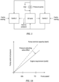
- FIG. 1 diagrammatically illustrates an example of such a system, where "idle” refers to operation of the engine at ground idle and "TO" refers to operation of the engine at take-off.
- FIG. 1A is a graph of pump outlet oil pressure versus pump speed having a first data line representative of engine oil system requirements and a second data line representative of the oil pump nominal capacity. The difference between the data lines reflects the effect of a PAV to adjust to meet the engine oil system requirements.
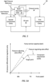
- a PRV controlled system may be configured to provide constant oil pump outlet pressure for all of the engine component cavities (e.g., see FIGS. 2 and 2A ), or a constant flow to respective regulated cavities (e.g., see FIGS. 3 and 3A ).
- PRVs are always on the hunt to maintain a constant differential pressure between low and high pressure references and to dampen any pressure spike that may occur due to sudden accessory transient oil demand, fluctuating temperatures, altitude and the like.
- a multi-adjustable valve for metering a flow of fluid within a lubrication system.
- the valve has a longitudinal axis and includes a biasing member, a housing, a first adjustable piston, a second adjustable piston, and a spool.
- the housing has an interior cavity, a fluid inlet port, and a fluid outlet port.
- the interior cavity extends between first and second ends of the housing.
- the first adjustable piston is configured for threaded engagement with the housing interior cavity adjacent to the first end of the housing.
- the first adjustable piston is axially moveable within the housing interior cavity via the threaded engagement with the housing interior cavity.
- the second adjustable piston has a shaft and a head disposed at a distal end of the shaft.
- the shaft is configured for threaded engagement with the first adjustable piston.
- the second adjustable piston is axially moveable via the threaded engagement between the shaft and the first adjustable piston.
- the spool has a spool shaft connected to and extending between a spring housing (SH) and an end cap. The end cap is disposed adjacent to the second end of the housing.
- the spring housing has an SH interior cavity configured to receive the biasing member.
- the spool is configured for axial movement within the housing interior cavity.
- the second adjustable piston head is disposed in the spring housing and the biasing member is disposed between the second adjustable piston head and a base surface of the spring housing. In a compressed state, the biasing member produces a biasing force that biases the spool toward the second end of the housing.
- the multi-adjustable valve is configured to receive fluid at a first pressure between the spring housing and the first end of the housing, and to receive fluid at a second pressure between the spool end cap and the second end of the housing, and during use the multi-adjustable valve meters flow of the fluid by the spool spring housing entirely blocking the housing fluid outlet port, or partially blocking the housing fluid outlet port, or not blocking the housing fluid outlet port as a function of a difference between the first pressure and the second pressure and the biasing force.
- the housing may include first and second housing segments.
- the first housing segment extends between the first end of the housing and the second housing segment and the second housing segment extends between the second end of the housing and the second housing segment.
- the housing interior cavity may include a first interior cavity (FIC) disposed in the first housing segment and a second interior cavity (SIC) disposed in the second housing segment.
- the first interior cavity may have an FIC inner diameter and the second interior cavity has an SIC inner diameter, and the FIC inner diameter may be greater than the SIC inner diameter.
- the fluid inlet and outlet ports may be disposed in the second housing segment, and the fluid outlet port may be axially disposed between the fluid inlet port and the first housing segment.
- the first interior cavity disposed in the first housing segment may have a FIC inner diameter surface that defines the FIC inner diameter, and the FIC inner diameter surface may be configured for the threaded engagement with the first adjustable piston.
- the first adjustable piston may include an FAP interior cavity and the second adjustable piston shaft may be in threaded engagement with the FAP interior cavity.
- the first adjustable piston may extend axially between FAP first and second axial ends, and may include a distal end flange disposed at the FAP second axial end.
- the distal end flange may be disposed within the SH interior cavity.
- the threaded engagement between the second adjustable piston shaft and the FAP interior cavity permits selective axial positioning of the second adjustable piston head relative to the distal end flange within the SH interior cavity.
- the SH interior cavity may include first and second SH interior cavities.
- the first SH interior cavity may have a first SH interior cavity inner diameter and the second SH interior cavity may have a second SH interior cavity inner diameter.
- the second SH interior cavity inner diameter may be equal to or greater than the first SH interior cavity diameter.
- the distal end flange (DEF) may have a DEF outer radial diameter, and the DEF outer radial diameter may be less than the second SH interior cavity inner diameter.
- the DEF outer radial diameter may be equal or greater than the first SH interior cavity diameter.
- the second adjustable piston (SAP) head may have has an SAP head outer radial surface disposed at an SAP head outer radial diameter, and the SAP head outer radial diameter may be greater than the first SH interior cavity diameter.
- the distal end flange may include one or more vent apertures.
- the spool end cap may be T-shaped with a first EC portion having a first EC portion outer radial surface disposed at a first EC portion outer radial diameter, and a second EC portion extending axially outward from the first EC portion.
- the second EC portion having a second EC portion outer radial surface may be disposed at a second EC portion outer radial diameter.
- the first EC portion outer radial diameter may be greater than the second EC portion outer radial diameter.
- a lubrication system for providing a fluid to one or more component cavities associated with an aircraft propulsion system.
- the system includes a tank, a pressure pump, and a multi-adjustable valve.
- the tank is configured to hold a volume of the fluid.
- the pressure pump is configured to pump the fluid to the one or more component cavities.
- the multi-adjustable valve is configured to control a pressure differential of a flow of the fluid across at least one of the component cavities.
- the multi-adjustable valve has a longitudinal axis and includes a biasing member, a housing, a first adjustable piston, a second adjustable piston, and a spool.
- the housing has an interior cavity, fluid inlet and outlet ports.
- the interior cavity extends between first and second ends of the housing.
- the first adjustable piston is configured for threaded engagement with the housing interior cavity adjacent the first end of the housing.
- the first adjustable piston is axially moveable within the housing interior cavity via the threaded engagement with the housing interior cavity.
- the second adjustable piston has a shaft and a head disposed at a distal end of the shaft.
- the shaft is configured for threaded engagement with the first adjustable piston.
- the second adjustable piston is axially moveable via the threaded engagement between the shaft and the first adjustable piston.
- the spool has a spool shaft connected to and extending between a spring housing (SH) and an end cap.
- the end cap is disposed adjacent to the second end of the housing.
- the spring housing has an SH interior cavity configured to receive the biasing member.
- the spool is configured for axial movement within the housing interior cavity.
- the second adjustable piston head is disposed in the spring housing and the biasing member is disposed between the second adjustable piston head and a base surface of the spring housing. In a compressed state, the biasing member produces a biasing force that biases the spool toward the second end of the housing.
- the valve is configured to receive the fluid at a first pressure between the spring housing and the first end of the housing, and to receive the fluid at a second pressure between the spool end cap and the second end of the housing.
- the multi-adjustable valve is configured to meter the flow of the fluid through the housing fluid inlet port and the housing fluid outlet port by the spool spring housing entirely blocking the housing fluid outlet port, or partially blocking the housing fluid outlet port, or not blocking the housing fluid outlet port as a function of a difference between the first pressure and the second pressure and the biasing force.
- a multi-adjustable valve for a flow of fluid within a lubrication system has a longitudinal axis and includes a biasing member, a housing, a first adjustable piston, a second adjustable piston, and a spool.
- the housing has an interior cavity, an inlet fluid port, and an outlet fluid port.
- the first adjustable piston is disposed in the housing interior cavity and is positionally adjustable within the housing interior cavity and is configured to produce a pressure adjusting effect on the flow of fluid.
- the biasing member is axially disposed between the second adjustable piston and the spool.
- the second adjustable piston is disposed within the housing interior cavity and is attached to the first adjustable piston and is positionally adjustable relative to the first adjustable piston, wherein the second adjustable piston, the biasing member, and the spool are configured to produce a pressure regulating effect on the flow of fluid.
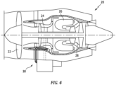
- FIG. 4 illustrates an aircraft propulsion system having a gas turbine engine 20 that includes a fan section 22, a compressor section 24, a combustor 26, and a turbine section 28.
- the present disclosure may be used within conventional through-flow or reverse flow gas turbine engines, gas turbine engine types such as turbofan engines, turboprop engines, turboshaft engines, and internal combustion engines as well.
- the engine 20 further comprises one or more fluid systems, such as a lubrication system 30 that circulates a fluid lubricant (e.g., which may be referred to hereinafter as "oil”) to both lubricate and cool components; e.g., bearings, gears (e.g., within a gearbox), and other components.
- a fluid lubricant e.g., which may be referred to hereinafter as "oil”
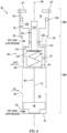
- FIG. 5 diagrammatically illustrates a non-limiting embodiment of a present disclosure aircraft engine lubrication system 30.
- FIG. 5A is a graph of oil pressure differential at a regulated component cavity versus pressure pump speed for the system diagrammatically shown in FIG. 5 .
- the system embodiment includes an oil tank 32, a pressure pump 34, and a multi-adjustable valve 36 for providing lubrication to a plurality of component cavities; e.g., "first component cavity” and "second component cavity”.
- component cavity unless otherwise indicated, is used to refer to a component that may be associated with the aircraft propulsion system that utilizes oil as a lubricant and/or as a coolant.
- Such a component may be an engine component, or a component that is peripheral to the engine, or the like.
- Non-limiting examples of component cavities include gearboxes, bearings (including journal bearings), engine mounted aircraft accessories, or engine / engine peripheral structures that utilize oil as a lubricant and/or as a coolant.
- the present disclosure lubricant system is not limited to including an oil tank 32, a pressure pump 34, and a multi-adjustable valve 36 and may include, for example, a scavenge pump, a deaerator, flow control devices such as valves, filters, separators, heat exchangers, sensors, and the like.
- the present disclosure lubricant system is also not limited to servicing only a first and second component cavity, and may be used to service more than two component cavities.
- the oil tank 32 is a reservoir configured to hold a volume of oil or other fluid lubricant.
- the oil tank has at least one fluid inlet, at least one fluid outlet, and typically includes a gas (e.g., air) vent.
- the size and configuration of the oil tank 32 may vary depending on the system.
- the pressure pump 34 may be a positive displacement pump such as a geared pump.
- the pressure pump 34 may be in mechanical communication with the engine; e.g., via a gearbox.
- the present disclosure is not limited to any particular type of pressure pump 34; e.g., an electrically driven pump may be used.
- Components within the present disclosure system may be connected to one another by a respective fluid line; e.g., a pipe, a tube, or the like configured to contain and permit passage of a fluid therethrough.
- a respective fluid line e.g., a pipe, a tube, or the like configured to contain and permit passage of a fluid therethrough.
- in fluid communication is used herein to mean that a fluid line extends between the named components and is configured to contain a fluid flow between the components.
- FIG. 5 diagrammatically illustrates a present disclosure aircraft engine lubrication system embodiment.
- oil may be drawn from the oil tank 32 by the pressure pump 34 and supplied by the pressure pump 34 to the first component cavity and the second component cavity.
- the oil is returned from the first component cavity and the second component cavity to the oil tank 32.
- system embodiments may include other components such as scavenge pumps, deaerators, and the like.
- the multi-adjustable valve 36 configured to control oil flow across the pressure pump 34, and consequently oil flow within the lubricating system is diagrammatically shown.
- the multi-adjustable valve 36 is configured to produce a pressure adjusting valve effect and a pressure regulating valve effect.
- the multi-adjustable valve 36 includes a housing 38, a spool 40, a first adjustment piston 42, a second adjustment piston 44, and a biasing member 46.
- the multi-adjustable valve 36 has a lengthwise (i.e., axial) extending axis 48.
- the biasing member 46 may be any structure that can produce a biasing force upon being compressed. Non-limiting examples of a biasing member 46 are a coil spring, a pair of Belleville washers stacked in opposing orientation, and the like.
- the housing 38 has a first housing segment 38A and a second housing segment 38B and extends lengthwise along the lengthwise axis 48 between a first end 50 and a second end 52. In the embodiment shown in FIG. 7 , the second end 52 of the housing 38 is closed.
- the first housing segment 38A extends from the first end 50 to the second housing segment 38B, and the second housing segment 38B extends from the second end 52 to the first housing segment 38A.
- the first housing segment 38A (FS) has an FS interior cavity 54 that is defined by an FS inner diameter surface 56 disposed at a first inner diameter (FS1).
- the second housing segment (SS) has a SS interior cavity 58 defined by a SS inner diameter surface 60 disposed at a second inner diameter (SS1).
- the first inner diameter is greater than the second inner diameter (FS1 > SS1).
- a shoulder 62 extends radially between the first and second housing segments 38A, 38B. At least a portion of the FS inner diameter surface 56 of the FS interior cavity 54 is configured for threaded engagement with the first adjustment piston 42 as will be detailed herein.
- the second housing segment 38B includes at least one fluid outlet port 64 and at least one fluid inlet port 66.
- a retainer ring 67 (e.g., a snap ring, a spiral retaining ring, or the like) may be disposed adjacent to the first end 50 of the housing 38.
- the housing includes a high reference point inlet 63 and a low reference point inlet 65.
- the high reference point inlet 63 is disposed to provide a fluid inlet on the second end 52 side of the spool end cap 68.
- FIG. 7A illustrates in dashed lines alternative positions for the high reference point inlet 63 to accommodate different spool end cap 68 configurations; e.g., see FIGS. 8 and 8A .
- the low reference point imposes its pressure in the interior cavity 54 of the first housing segment and in the first internal cavity portion 88 of the spring housing 70, while the high pressure reference imposes its pressure in the region below the spool cap 68 of the spool 40.
- the spool 40 includes an end cap 68 and a spring housing 70 connected to one another by a spool shaft 72.
- the spool 40 extends along the lengthwise axis 48.
- the spring housing 70 is disposed at one lengthwise end of the spool 40 and the end cap 68 is disposed at the opposite lengthwise end of the spool 40.
- the end cap 68 (EC) has a "T" configuration with a first EC portion 68A and a second EC portion.
- the first EC portion has an outer radial surface 74 that extends between a first axial surface 76 and a second axial surface 78 lengthwise spaced apart from one another.
- the first EC portion outer radial surface 74 is disposed at an outer radial diameter (EC1).
- the second EC portion 68B extends an axial distance "ECA1" out from the second axial surface 78 of the first EC portion 68A.
- the second EC portion 68B has an outer radial surface 80 disposed at an outer radial diameter (EC2) that is less than the first outer radial diameter (EC1 > EC2).
- the outer radial diameter EC1 of the first EC portion 68A is less than the SS interior cavity inner diameter SS1 to permit the end cap 68 to axially travel within the second housing segment 38B.
- a fluid seal may be disposed between the end cap outer radial surface 74 (at EC1) and the SS interior cavity inner diameter surface 60.
- the present disclosure is not limited to an end cap 68 having a "T"-shaped configuration.
- a non-limiting example of an alternative end cap 68 configuration is the "U"-shaped end cap shown in FIG. 8A .
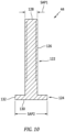
- the spool spring housing 70 has an outer radial surface 82 that extends lengthwise between a first axial end surface 84 and a second axial end surface 86.
- the spring housing 70 further includes a first internal cavity portion 88 and a second internal cavity portion 90, both disposed on the lengthwise axis 48.
- the first internal cavity (FIC) portion 88 extends an axial distance "A2" from the first axial end surface 84 to a base surface 92.
- the first internal cavity portion 88 has a FIC inner diameter surface 94 disposed at an inner diameter (FIC1).
- the second internal cavity (SIC) portion 90 is disposed axially inward from the first axial end surface 84 an axial distance "A3" and extends an axial distance "A4".
- the second internal cavity portion 90 has a SIC inner diameter surface 96 disposed at an inner diameter (SIC1).
- the FIC inner diameter is less than the SIC inner diameter (SIC1 > FIC1).
- shoulder surfaces 98 are disposed therebetween.
- segment of the first internal cavity portion 88 disposed between the second internal cavity portion 90 and the first axial end surface 84 i.e., the segment extending an axial distance "A3" is shown as having the same diameter as the segment of the first internal cavity portion 88 disposed on the opposite side of the second internal cavity portion 90.
- the present disclosure is not limited to these two first internal cavity portion 88 segments having the same diameter; e.g., the segment of the first internal cavity portion 88 disposed between the second internal cavity portion 90 and the first axial end surface 84 (i.e., the segment extending an axial distance "A3") may have a different diameter, for example a larger diameter.
- the spring housing 70 is diagrammatically shown as a unitary body, with the portion of the first internal cavity 88 extending between the first axial end surface 84 to the second internal cavity portion 90 part of that unitary body.
- the present disclosure is not limited to a spool 40 configured as a unitary body.
- the portion of the spring housing 70 defining the first internal cavity portion 88 between the first axial end surface 84 to the second internal cavity portion 90 may be an independent component attached by fastener, or the like; e.g., to facilitate assembly.
- balancing grooves may be disposed in the outer radial surface 82 of the spool spring housing 70 and in the outer radial surface 74 of the end cap 68.
- the balancing grooves are not required but may be included to facilitate movement of the spool 40.
- the first adjustment piston 42 has a FAP first segment 42A and a FAP second segment 42B.
- the FAP first segment 42A has an outer radial surface 100 that extends lengthwise between an end surface 102 and a shoulder surface 104.
- the FAP first segment outer radial surface 100 is disposed at a diameter FS1.
- At least a portion of the FAP first segment outer radial surface 100 is configured for threaded engagement with the housing FS inner diameter surface 56 as will be detailed herein.
- the FAP first segment 42A includes a first interior cavity 106 having an inner diameter surface 108 disposed at a diameter FS2.
- the first interior cavity 106 is open at the end surface 102 and extends axially inward a distance.
- the FAP second segment 42B has an outer radial surface 110 that extends lengthwise from the shoulder surface 104 to a distal end flange 112.
- the FAP second segment outer radial surface 110 is disposed at a diameter FS3.
- the FAP second segment 42B includes a second interior cavity 114 having an inner diameter surface 116 disposed at a diameter FS4.
- the second interior cavity 114 is open at the distal end flange 112 and is open to the first interior cavity 106 of the FAP first segment 42A. At least a portion of the inner diameter surface 116 of the second interior cavity 114 is configured for threaded engagement with the shaft of the second adjustment piston 44 as will be detailed herein.
- the distal end flange 112 has an outer radial surface 118 disposed at a diameter FS5.
- the distal end flange 112 may include one or more vent apertures 120 configured to vent any pressure difference between the interior cavities of the spring housing 70 and the interior of the housing 38; e.g., pressure differences that may result from thermal gradient, or assembly or spool 40 movement.
- the second adjustment piston 44 has a shaft 122 and a head 124.
- the shaft 122 has an outer radial surface 126 disposed at a diameter SAP1 that extends lengthwise between an end surface 128 and the head 124. At least a portion of the shaft outer radial surface 126 is configured for threaded engagement with the inner diameter surface 116 of the second interior cavity 114 of the second adjustment piston 44 as will be detailed herein.
- the head 124 has an axial end surface 130 and an outer radial surface 132. The head outer radial surface is disposed at a diameter SAP2.
- the spool 40 is disposed for axial movement within the second housing segment 38B of the housing 38.
- the end cap 68 is disposed axially below the housing fluid inlet port 66 and the spring housing 70 may be axially aligned with the housing fluid outlet port 64 to close or partially close the housing fluid outlet port 64, or may be disposed axially above the housing fluid outlet port 64 so it is fully open.
- the first and second adjustment pistons 42, 44 are disposed within the interior cavities 54, 58 of the housing 38.
- the FAP first segment 42A of the first adjustment piston 42 is disposed within the first housing segment 38A.
- a portion of the outer radial surface 100 of the FAP first segment 42A is threadedly engaged with the housing FS inner diameter surface 56. The threaded engagement allows axial movement and positioning of the first adjustment piston 42 relative to the housing 38. As diagrammatically shown in FIG.
- a seal 134 (e.g., packing or the like) may be disposed between the outer radial surface 100 of the FAP first segment and the FS inner diameter surface 56 to inhibit fluid flow therebetween.
- the shaft 122 of the second adjustment piston 44 is received within the second interior cavity 114 of the first adjustment piston 42 and is threadedly engaged with the inner diameter surface 116 of the second interior cavity 114 of the first adjustment piston 42. The threaded engagement allows axial movement and positioning of the first adjustment piston 42 and second adjustment piston 44 relative to one another. As diagrammatically shown in FIG.
- a seal 136 (e.g., packing or the like) may be disposed between the shaft 122 of the second adjustment piston 44 and the inner diameter surface 116 of the second interior cavity 114 of the first adjustment piston 42 to inhibit fluid flow therebetween.
- the distal end flange 112 of the first adjustment piston 42 is disposed within the second internal cavity portion 90 of the spool spring housing 70.
- the outer radial diameter (FS5) of the distal end flange 112 is less than the inner diameter (SIC1) of the second internal cavity portion 90 of the spool spring housing 70 (i.e., FS5 ⁇ SIC1).
- SIC1 inner diameter of the second internal cavity portion 90 of the spool spring housing 70
- the head 124 of the second adjustment piston 44 is also disposed and retained within the second internal cavity portion 90 of the spool spring housing 70.
- the biasing member 46 is disposed within the spool spring housing 70 between the head 124 of the second adjustment piston 44 and the base surface 92 of the first internal cavity portion 88 of the spring housing 70.
- the biasing member 46 is in contact with and provides a biasing force between the head 124 of the second adjustment piston 44 and the base surface 92 of the first internal cavity portion 88 of the spring housing 70.
- the adjustability of the first adjustment piston 42 relative to the housing 38 enables the present disclosure multi-adjustable valve 36 to provide a pressure adjusting valve (PAV) effect and the adjustability of the second adjustment piston 44 relative to the first adjustment piston 42 enables the present disclosure multi-adjustable valve 36 to provide a pressure regulating valve (PRV) effect.
- PAV pressure adjusting valve
- PRV pressure regulating valve
- the present disclosure multi-adjustable valve 36 provides the benefits of a PAV and a PRV without the need to provide both a PAV and a PRV (independent of one another), and also overcomes the disadvantages of a PAV alone or a PRV alone.
- the oil inlet pressure to a component cavity is linked to the oil pump speed.
- control hardware e.g., variable size orifices
- each lubrication system is unique (e.g., different tolerances, and the like)
- the control hardware for each component cavity will need to be sized uniquely. This process can be time consuming and arduous.
- Prior art PRV controlled systems in contrast, fluctuate to maintain a constant difference in pressure between low and high reference points.
- the high reference point is a fluid pressure source that may be associated with oil static pressure and the low reference point is a fluid pressure source that may be associated with ambient pressure.
- the high reference point and low reference point may be chosen for a variety of reasons.
- the high and low reference points may be chosen to protect a specific component / cavity in which case the aforesaid reference points may be upstream and downstream of the cavity / component.
- the reference points may be chosen such that the high reference point will be "upstream of everything" (e.g., the pump exit) and the low reference point will be "downstream of everything”; i.e., a vent to ambient, or a tank point.
- the low reference point imposes its pressure in the first internal cavity portion 88 of the spring housing 70, while the high pressure reference imposes its pressure in the region below the spool cap 68 of the spool 40.
- a significant drawback of prior art PRV systems is that a substantial amount of oil flow is bypassed through the PRV; e.g., about X percent at ground idle and about 4X percent under take-off conditions.
- the design point for a prior art PRV system is typically the bypass flow at ground idle, and the system is oversized for take-off conditions.
- the oil pressure pump is oversized for take-off conditions; e.g., heavier than desired and likely more expensive (e.g., power consumption) than desired.
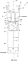
- FIG. 11A-D diagrammatically illustrate a present disclosure multi-adjustable valve 36 and relative movements of components thereof.
- FIG. 11 diagrammatically illustrates the present disclosure multi-adjustable valve 36 in an unadjusted configuration.
- the first adjustment piston 42 is disposed an axial distance (AD1) extending from the retaining ring 67 at the housing first end 50 toward the housing second end 52. Because the second adjustment piston 44 is in threaded engagement with the first adjustment piston 42, the second adjustment piston 44 travels axially with the first adjustment piston 42.
- FIG. 11 shows the spool spring housing 70 blocking the fluid outlet port(s) 64 of the housing 38, and the end cap 68 of the spool 40 is disposed proximate to the second end 52 of the housing 38.
- the region (referred to hereinafter as the "HPR region") below the end cap 68 of the present disclosure valve is subject to fluid pressure at a high pressure reference, and the region (referred to hereinafter as the "LPR region") between the spool spring housing 70 and the first segment 42A of the first adjustment piston 42 is subject to fluid pressure at a low pressure reference; e.g., see also FIG. 6 . Consequently, there will be a fluid pressure difference across the spool 40 between the HPR region and the LPR region in most operating conditions. If the biasing member 46 is uncompressed, it can be assumed that the biasing member 46 exerts no force against the spool 40 in a direction toward the second end 52 of the housing 38.
- FIG. 11A shows an adjusted present disclosure valve 36.
- the end surface 102 of the first adjustment piston 42 is disposed proximate to the first end 50 of the housing 38
- the head 124 of the second adjustment piston 44 is proximate to the first axial end surface 84 of the spool spring housing 70
- the end cap 68 of the spool 40 is spaced apart from the second end 52 of the housing 38
- the biasing member 46 is not compressed.
- the spool spring housing 70 partially blocks the fluid outlet port(s) 64 of the housing 38.
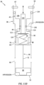
- FIG. 11B illustrates the first adjustment piston 42 in the same position as shown in FIG. 11 .
- the second adjustment piston 44 is axially moved (e.g., via screw travel) relative to the first adjustment piston 42 toward the second end 52 of the housing 38.
- the axial movement of the second adjustment piston 44 causes the biasing member 46 to compress.
- FIG. 11B shows the spool spring housing 70 blocking the fluid outlet port(s) 64 of the housing 38, and the end cap 68 of the spool 40 disposed proximate to the second end 52 of the housing 38.
- the diagrammatic representation of the multi-adjustable valve 36 shown in FIG. 11B is indicative of a scenario wherein the speed of the pressure pump 34 is below the target point as shown in FIG. 5A .
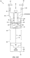
- FIG. 11C illustrates the first adjustment piston 42 in the same position as shown in FIG. 11B , and the second adjustment piston 44 in the same position as shown in FIG. 11B .
- the spool 40 has moved axially toward the first end 50 of the housing 38 to a position wherein the spool spring housing 70 does not entirely block the fluid outlet port(s) 64 of the housing 38, and the end cap 68 of the spool 40 is now spaced apart from the second end 52 of the housing 38 by a distance EC1.
- the axial movement of the spool 40 toward the first end 50 of the housing 38 causes further compression of the biasing member 46.
- the axial movement of the spool 40 results from the fluid pressure in the HPR region being greater than the combined force of the fluid pressure in the LPR region and the biasing force.
- the diagrammatic representation of the multi-adjustable valve 36 shown in FIG. 11C is indicative of a scenario wherein the speed of the pressure pump 34 is above the target point as shown in FIG. 5A .
- FIG. 11D illustrates the first adjustment piston 42 in the same position as shown in FIGS. 11B and 11C , and the second adjustment piston 44 in the same position as shown in FIGS. 11B and 11C .
- the spool 40 has moved axially toward the first end 50 of the housing 38 to a position wherein the spool spring housing 70 does not block the fluid outlet port(s) 64 of the housing 38.
- the end cap 68 of the spool 40 is now spaced apart from the second end of the housing 38 by a distance EC2, where EC2 > EC1.
- the axial movement of the spool 40 toward the first end 50 of the housing 38 causes further compression of the biasing member 46.
- the axial movement of the spool 40 results from the fluid pressure in the HPR region being greater than the combined force of the fluid pressure in the LPR region and the biasing force.
- multi-adjustable valve 36 may be configured to limit the extent to which the biasing member 46 may be compressed; e.g., to avoid the biasing member 46 from being fully compressed.
- the diameter (SAP2) of the second adjustment piston head 124 may be selected to be greater than the diameter (FIC1 - see FIG.
- FIG. 11D The diagrammatic representation of the multi-adjustable valve 36 shown in FIG. 11D is indicative of a scenario wherein the speed of the pressure pump 34 is above the target point as shown in FIG. 5A .
- FIG. 11D indicates a scenario where the speed of the pressure pump 34 is even higher above the target point than indicated in FIG. 11C and the fluid pressure from the high reference point is higher than that in FIG. 11C .
- an adjustment sequence for the present disclosure multi-adjustable valve 36 includes initially adjusting the axial position of the first adjustment piston 42 relative to the housing 38 via the threaded engagement between the first adjustment piston 42 and the housing 38. As detailed above relative to FIG. 11A , the first adjustment piston 42 has moved an axial distance (AD1) away from the housing first end 50, toward the housing second end 50.
- AD1 axial distance
- This adjustment (up or down axially) may be used to change the position of the spool spring housing 70 relative to the fluid outlet port 64 and thereby adjust the amount of bypass fluid flow through the valve 36 at rest. This adjustment alters the amount of fluid flow between the housing fluid inlet port 66 and the housing outlet port 64 at rest.
- the term “at rest” or “bypass flow at rest” refers to the fluid flow through the valve 36 when the biasing member 46 has not been compressed by the difference in pressure between the high and low pressure references.
- This valve 36 setting adjustment may be performed with the engine operating at a ground idle condition.
- This valve 36 setting adjustment sets the difference in pressure (dP) versus engine speed (RPMs) slope from 0 to a "target point”; e.g., see the chart shown in FIG.
- the next step in the adjustment procedure may include adjusting the axial position of the second adjustment piston 44 relative to the first adjustment piston 42 via the threaded engagement therebetween.
- the axial position of the second adjustment piston 44 relative to the first adjustment piston 42 can be adjusted to set a desired constant dP versus pump RPM level; e.g., see FIG. 5A .
- the adjustment of the second adjustment piston 44 sets the axial spring length (i.e., the amount of spring compression), and therefore the amount of spring bias force.
- the high pressure reference equivalent force would need to be great enough to overcome the low pressure reference equivalent force and the biasing force; e.g., see FIG. 11D .
- This valve 36 adjustment pressure setting could be based on engine take-off conditions.
- first adjustment piston 42 is in threaded engagement with housing 38 and the second adjustment piston 44 is in threaded engagement with the first adjustment piston 42.
- the aforesaid threaded engagements allow selective positioning of the first adjustment piston 42 and the second adjustment piston 44 relative to each other and relative to other components.
- the present disclosure is not limited to having the first adjustment piston 42 in threaded engagement with housing 38 and the second adjustment piston 44 in threaded engagement with the first adjustment piston 42.
- washers may be disposed between a shoulder 62 surface between the first and second housing segments 38A, 38B and the second axial end surface 86 of the spool spring housing 70, and/or between a shoulder surface 98 of the spring housing second internal cavity portion 90 and the upper axial surface of the distal end flange 112 of the first adjustment piston 42.
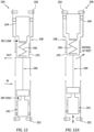
- FIGS. 12-12C illustrate an alternative multi-adjustable valve 236 embodiment having a housing 238, a spool 240, a first adjustment piston 242, a second adjustment piston 244, and a biasing member 246.
- the first adjustment piston 242 is disposed adjacent the second end 252 of the housing 238, the second adjustment piston 244 is disposed adjacent the first end 250 of the housing 238, and the spool 240 and biasing member 246 are disposed between the first and second adjustment pistons 242, 244.
- the first adjustment piston 242 is in threaded engagement with the housing 238 adjacent the second end 252 of the housing 238, and the second adjustment piston 244 is in threaded engagement with the housing 238 adjacent the first end 250 of the housing 238.
- the first adjustment piston 242 may be initially adjusted (e.g., moved axially via the threaded engagement) to dispose the spool spring housing 270 at a bypass at rest position (see FIG. 12A ). Subsequently, the second adjustment piston 244 may be adjusted (e.g., moved axially via the threaded engagement) to set the desired dP versus pump RPM level (see FIG. 12B).
- FIG. 12C illustrates the valve 236 in a full bypass configuration, with the spool 240 moved axially toward the first end 250 of the housing 238 and the biasing member 246 compressed.
- This alternative multi-adjustable valve 236 embodiment in contrast with the embodiments shown in FIGS. 11-11D , is configured such that positional adjustment of either adjustment piston 242, 244 can influence the preload of the biasing member 246.
- any one of these structures may describe the operations as a sequential process, many of the operations can be performed in parallel or concurrently.
- the order of the operations may be rearranged.
- a process may correspond to a method, a function, a procedure, a subroutine, a subprogram, etc.
Landscapes
- Engineering & Computer Science (AREA)
- General Engineering & Computer Science (AREA)
- Mechanical Engineering (AREA)
- Chemical & Material Sciences (AREA)
- Combustion & Propulsion (AREA)
- Safety Valves (AREA)
- Fluid-Driven Valves (AREA)
Abstract
A multi-adjustable valve (36) for a flow of fluid within a lubrication system (30) is provided, having a longitudinal axis (48). The valve (36) includes a biasing member (46), a housing (38), first and second adjustable pistons (42, 44), and a spool (40). The housing (38) has an interior cavity and inlet and outlet fluid ports (64, 66). The first adjustable piston (42) is disposed in the housing interior cavity and is positionally adjustable within the housing interior cavity and is configured to produce a pressure adjusting effect on the flow of fluid. The biasing member (46) is axially disposed between the second adjustable piston (44) and the spool (40). The second adjustable piston (44) is disposed within the housing interior cavity and is attached to the first adjustable piston (42) and is positionally adjustable relative to the first adjustable piston (42), wherein the second adjustable piston (44), the biasing member (46), and the spool (40) are configured to produce a pressure regulating effect on the flow of fluid.
Description
- The present disclosure relates gas turbine engine fluid lubrication systems in general and to valves for controlling a flow of a fluid lubricant in particular.
- Aircraft engine oil systems are designed to lubricate and cool components that engage and disengage, such as gears, bearings, and journal bearings or static elements such as internal cavity walls to avoid overheating. To accomplish these functions, oil is typically circulated through an oil tank, a pressure oil pump, one or more cavities containing the components requiring oil, and then back to the oil tank. The oil flow pressure within the system can be controlled in different ways. For example, it is known to use an oil pressure adjusting valve (PAV) to control system oil pressure. In a PAV controlled system, the oil inlet pressure to a component cavity is typically proportional to the oil pump speed. The volumetric flow to each component cavity will, therefore, be proportional to the pressure differential for each respective component cavity relative to the oil pump outlet pressure, neglecting oil passage pressure losses.
FIG. 1 diagrammatically illustrates an example of such a system, where "idle" refers to operation of the engine at ground idle and "TO" refers to operation of the engine at take-off.FIG. 1A is a graph of pump outlet oil pressure versus pump speed having a first data line representative of engine oil system requirements and a second data line representative of the oil pump nominal capacity. The difference between the data lines reflects the effect of a PAV to adjust to meet the engine oil system requirements. - It is also known to use an oil pressure regulating valve (PRV) to control system oil pressure. Depending on where the reference pressure is located, a PRV controlled system may be configured to provide constant oil pump outlet pressure for all of the engine component cavities (e.g., see
FIGS. 2 and 2A ), or a constant flow to respective regulated cavities (e.g., seeFIGS. 3 and 3A ). - In contrast to PAVs, PRVs are always on the hunt to maintain a constant differential pressure between low and high pressure references and to dampen any pressure spike that may occur due to sudden accessory transient oil demand, fluctuating temperatures, altitude and the like.
- What is needed is an improved oil lubrication system and valving that makes the improvement possible, for example including a valve that provides PAV-like behavior below a given pressure threshold and PRV-like behavior above the pressure threshold.
- According to an aspect of the present disclosure, a multi-adjustable valve for metering a flow of fluid within a lubrication system is provided. The valve has a longitudinal axis and includes a biasing member, a housing, a first adjustable piston, a second adjustable piston, and a spool. The housing has an interior cavity, a fluid inlet port, and a fluid outlet port. The interior cavity extends between first and second ends of the housing. The first adjustable piston is configured for threaded engagement with the housing interior cavity adjacent to the first end of the housing. The first adjustable piston is axially moveable within the housing interior cavity via the threaded engagement with the housing interior cavity. The second adjustable piston has a shaft and a head disposed at a distal end of the shaft. The shaft is configured for threaded engagement with the first adjustable piston. The second adjustable piston is axially moveable via the threaded engagement between the shaft and the first adjustable piston. The spool has a spool shaft connected to and extending between a spring housing (SH) and an end cap. The end cap is disposed adjacent to the second end of the housing. The spring housing has an SH interior cavity configured to receive the biasing member. The spool is configured for axial movement within the housing interior cavity. The second adjustable piston head is disposed in the spring housing and the biasing member is disposed between the second adjustable piston head and a base surface of the spring housing. In a compressed state, the biasing member produces a biasing force that biases the spool toward the second end of the housing. The multi-adjustable valve is configured to receive fluid at a first pressure between the spring housing and the first end of the housing, and to receive fluid at a second pressure between the spool end cap and the second end of the housing, and during use the multi-adjustable valve meters flow of the fluid by the spool spring housing entirely blocking the housing fluid outlet port, or partially blocking the housing fluid outlet port, or not blocking the housing fluid outlet port as a function of a difference between the first pressure and the second pressure and the biasing force.
- In any of the aspects or embodiments described above and herein, the housing may include first and second housing segments. The first housing segment extends between the first end of the housing and the second housing segment and the second housing segment extends between the second end of the housing and the second housing segment. The housing interior cavity may include a first interior cavity (FIC) disposed in the first housing segment and a second interior cavity (SIC) disposed in the second housing segment. The first interior cavity may have an FIC inner diameter and the second interior cavity has an SIC inner diameter, and the FIC inner diameter may be greater than the SIC inner diameter.
- In any of the aspects or embodiments described above and herein, the fluid inlet and outlet ports may be disposed in the second housing segment, and the fluid outlet port may be axially disposed between the fluid inlet port and the first housing segment.
- In any of the aspects or embodiments described above and herein, the first interior cavity disposed in the first housing segment may have a FIC inner diameter surface that defines the FIC inner diameter, and the FIC inner diameter surface may be configured for the threaded engagement with the first adjustable piston.
- In any of the aspects or embodiments described above and herein, the first adjustable piston (FAP) may include an FAP interior cavity and the second adjustable piston shaft may be in threaded engagement with the FAP interior cavity.
- In any of the aspects or embodiments described above and herein, the first adjustable piston may extend axially between FAP first and second axial ends, and may include a distal end flange disposed at the FAP second axial end. The distal end flange may be disposed within the SH interior cavity. The threaded engagement between the second adjustable piston shaft and the FAP interior cavity permits selective axial positioning of the second adjustable piston head relative to the distal end flange within the SH interior cavity.
- In any of the aspects or embodiments described above and herein, the SH interior cavity may include first and second SH interior cavities. The first SH interior cavity may have a first SH interior cavity inner diameter and the second SH interior cavity may have a second SH interior cavity inner diameter. The second SH interior cavity inner diameter may be equal to or greater than the first SH interior cavity diameter. The distal end flange (DEF) may have a DEF outer radial diameter, and the DEF outer radial diameter may be less than the second SH interior cavity inner diameter. The DEF outer radial diameter may be equal or greater than the first SH interior cavity diameter.
- In any of the aspects or embodiments described above and herein, the second adjustable piston (SAP) head may have has an SAP head outer radial surface disposed at an SAP head outer radial diameter, and the SAP head outer radial diameter may be greater than the first SH interior cavity diameter.
- In any of the aspects or embodiments described above and herein, the distal end flange may include one or more vent apertures.
- In any of the aspects or embodiments described above and herein, the spool end cap (EC) may be T-shaped with a first EC portion having a first EC portion outer radial surface disposed at a first EC portion outer radial diameter, and a second EC portion extending axially outward from the first EC portion. The second EC portion having a second EC portion outer radial surface may be disposed at a second EC portion outer radial diameter. The first EC portion outer radial diameter may be greater than the second EC portion outer radial diameter.
- According to an aspect of the present disclosure, a lubrication system for providing a fluid to one or more component cavities associated with an aircraft propulsion system is provided. The system includes a tank, a pressure pump, and a multi-adjustable valve. The tank is configured to hold a volume of the fluid. The pressure pump is configured to pump the fluid to the one or more component cavities. The multi-adjustable valve is configured to control a pressure differential of a flow of the fluid across at least one of the component cavities. The multi-adjustable valve has a longitudinal axis and includes a biasing member, a housing, a first adjustable piston, a second adjustable piston, and a spool. The housing has an interior cavity, fluid inlet and outlet ports. The interior cavity extends between first and second ends of the housing. The first adjustable piston is configured for threaded engagement with the housing interior cavity adjacent the first end of the housing. The first adjustable piston is axially moveable within the housing interior cavity via the threaded engagement with the housing interior cavity. The second adjustable piston has a shaft and a head disposed at a distal end of the shaft. The shaft is configured for threaded engagement with the first adjustable piston. The second adjustable piston is axially moveable via the threaded engagement between the shaft and the first adjustable piston. The spool has a spool shaft connected to and extending between a spring housing (SH) and an end cap. The end cap is disposed adjacent to the second end of the housing. The spring housing has an SH interior cavity configured to receive the biasing member. The spool is configured for axial movement within the housing interior cavity. The second adjustable piston head is disposed in the spring housing and the biasing member is disposed between the second adjustable piston head and a base surface of the spring housing. In a compressed state, the biasing member produces a biasing force that biases the spool toward the second end of the housing. The valve is configured to receive the fluid at a first pressure between the spring housing and the first end of the housing, and to receive the fluid at a second pressure between the spool end cap and the second end of the housing. During use, the multi-adjustable valve is configured to meter the flow of the fluid through the housing fluid inlet port and the housing fluid outlet port by the spool spring housing entirely blocking the housing fluid outlet port, or partially blocking the housing fluid outlet port, or not blocking the housing fluid outlet port as a function of a difference between the first pressure and the second pressure and the biasing force.
- According to an aspect of the present disclosure, a multi-adjustable valve for a flow of fluid within a lubrication system is provided. The valve has a longitudinal axis and includes a biasing member, a housing, a first adjustable piston, a second adjustable piston, and a spool. The housing has an interior cavity, an inlet fluid port, and an outlet fluid port. The first adjustable piston is disposed in the housing interior cavity and is positionally adjustable within the housing interior cavity and is configured to produce a pressure adjusting effect on the flow of fluid. The biasing member is axially disposed between the second adjustable piston and the spool. The second adjustable piston is disposed within the housing interior cavity and is attached to the first adjustable piston and is positionally adjustable relative to the first adjustable piston, wherein the second adjustable piston, the biasing member, and the spool are configured to produce a pressure regulating effect on the flow of fluid.
- The foregoing features and elements may be combined in various combinations without exclusivity, unless expressly indicated otherwise. For example, aspects and/or embodiments of the present disclosure may include any one or more of the individual features or elements disclosed above and/or below alone or in any combination thereof. These features and elements as well as the operation thereof will become more apparent in light of the following description and the accompanying drawings. It should be understood, however, the following description and drawings are intended to be exemplary in nature and non-limiting.
-
-
FIG. 1 is a diagrammatic illustration of a lubrication system embodiment utilizing a pressure adjusting valve (PAV). -
FIG. 1A is a graph of pump outlet oil pressure versus pump speed for a lubrication system utilizing a PAV like that shown inFIG. 1 . -
FIG. 2 is a diagrammatic illustration of a lubrication system embodiment utilizing a pressure regulating valve (PRV). -
FIG. 2A is a graph of pump outlet oil pressure versus pump speed for a lubrication system utilizing a PRV like that shown inFIG. 2 . -
FIG. 3 is a diagrammatic illustration of a lubrication system embodiment utilizing a pressure regulating valve (PRV). -
FIG. 3A is a graph of pump outlet oil pressure versus pump speed for a lubrication system utilizing a PRV like that shown inFIG. 3 . -
FIG. 4 is a diagrammatic view of a gas turbine engine having a lubrication system. -
FIG. 5 is a diagrammatic illustration of a lubrication system embodiment utilizing a present disclosure multi-adjustable valve. -
FIG. 5A is a graph of oil pressure differential at a regulated component cavity versus pump speed for a lubrication system utilizing a present disclosure multi-adjustable valve like that shown inFIG. 5 . -
FIG. 6 is a diagrammatic view of a present disclosure multi-adjustable valve embodiment. -
FIG. 6A is an enlarged partial view of the valve embodiment shown inFIG. 6 . -
FIG. 7 is a diagrammatic view of a housing component embodiment that may be used in a present disclosure multi-adjustable valve. -
FIG. 8 is a diagrammatic view of a spool component embodiment that may be used in a present disclosure multi-adjustable valve. -
FIG. 8A is a partial view of a spool embodiment, illustrating an alternative end cap embodiment. -
FIG. 9 is a diagrammatic view of a first adjustment piston component embodiment that may be used in a present disclosure multi-adjustable valve. -
FIG. 9A is a planar view of a distal end flange embodiment of a first adjustment piston component embodiment like that shown inFIG. 9 . -
FIG. 10 is a diagrammatic view of a second adjustment piston component embodiment that may be used in a present disclosure multi-adjustable valve. -
FIGS. 11-11D are diagrammatic views of a present disclosure multi-adjustable valve embodiment, illustrating components of the multi-adjustable valve positionally varied. -
FIGS. 12-12C are diagrammatic views of a present disclosure multi-adjustable valve embodiment, illustrating components of the multi-adjustable valve positionally varied. -
FIG. 4 illustrates an aircraft propulsion system having agas turbine engine 20 that includes afan section 22, acompressor section 24, acombustor 26, and aturbine section 28. The present disclosure may be used within conventional through-flow or reverse flow gas turbine engines, gas turbine engine types such as turbofan engines, turboprop engines, turboshaft engines, and internal combustion engines as well. Theengine 20 further comprises one or more fluid systems, such as alubrication system 30 that circulates a fluid lubricant (e.g., which may be referred to hereinafter as "oil") to both lubricate and cool components; e.g., bearings, gears (e.g., within a gearbox), and other components. The present disclosure is not limited to use with any particular type of lubricant / oil. -
FIG. 5 diagrammatically illustrates a non-limiting embodiment of a present disclosure aircraftengine lubrication system 30.FIG. 5A is a graph of oil pressure differential at a regulated component cavity versus pressure pump speed for the system diagrammatically shown inFIG. 5 . The system embodiment includes anoil tank 32, apressure pump 34, and amulti-adjustable valve 36 for providing lubrication to a plurality of component cavities; e.g., "first component cavity" and "second component cavity". The term "component cavity", unless otherwise indicated, is used to refer to a component that may be associated with the aircraft propulsion system that utilizes oil as a lubricant and/or as a coolant. Such a component may be an engine component, or a component that is peripheral to the engine, or the like. Non-limiting examples of component cavities include gearboxes, bearings (including journal bearings), engine mounted aircraft accessories, or engine / engine peripheral structures that utilize oil as a lubricant and/or as a coolant. The present disclosure lubricant system is not limited to including anoil tank 32, apressure pump 34, and amulti-adjustable valve 36 and may include, for example, a scavenge pump, a deaerator, flow control devices such as valves, filters, separators, heat exchangers, sensors, and the like. The present disclosure lubricant system is also not limited to servicing only a first and second component cavity, and may be used to service more than two component cavities. - The
oil tank 32 is a reservoir configured to hold a volume of oil or other fluid lubricant. The oil tank has at least one fluid inlet, at least one fluid outlet, and typically includes a gas (e.g., air) vent. The size and configuration of theoil tank 32 may vary depending on the system. - The
pressure pump 34 may be a positive displacement pump such as a geared pump. Thepressure pump 34 may be in mechanical communication with the engine; e.g., via a gearbox. The present disclosure is not limited to any particular type ofpressure pump 34; e.g., an electrically driven pump may be used. - Components within the present disclosure system may be connected to one another by a respective fluid line; e.g., a pipe, a tube, or the like configured to contain and permit passage of a fluid therethrough. The term "in fluid communication" is used herein to mean that a fluid line extends between the named components and is configured to contain a fluid flow between the components.
- As stated above,
FIG. 5 diagrammatically illustrates a present disclosure aircraft engine lubrication system embodiment. In this example, oil may be drawn from theoil tank 32 by thepressure pump 34 and supplied by thepressure pump 34 to the first component cavity and the second component cavity. The oil is returned from the first component cavity and the second component cavity to theoil tank 32. Also as stated above, system embodiments may include other components such as scavenge pumps, deaerators, and the like. - Referring to
FIG. 6 , an embodiment of a present disclosuremulti-adjustable valve 36 configured to control oil flow across thepressure pump 34, and consequently oil flow within the lubricating system is diagrammatically shown. Themulti-adjustable valve 36 is configured to produce a pressure adjusting valve effect and a pressure regulating valve effect. Themulti-adjustable valve 36 includes ahousing 38, aspool 40, afirst adjustment piston 42, asecond adjustment piston 44, and a biasingmember 46. Themulti-adjustable valve 36 has a lengthwise (i.e., axial) extendingaxis 48. The biasingmember 46 may be any structure that can produce a biasing force upon being compressed. Non-limiting examples of a biasingmember 46 are a coil spring, a pair of Belleville washers stacked in opposing orientation, and the like. - Referring to
FIG. 7 , thehousing 38 has afirst housing segment 38A and asecond housing segment 38B and extends lengthwise along thelengthwise axis 48 between afirst end 50 and asecond end 52. In the embodiment shown inFIG. 7 , thesecond end 52 of thehousing 38 is closed. Thefirst housing segment 38A extends from thefirst end 50 to thesecond housing segment 38B, and thesecond housing segment 38B extends from thesecond end 52 to thefirst housing segment 38A. Thefirst housing segment 38A (FS) has an FSinterior cavity 54 that is defined by an FSinner diameter surface 56 disposed at a first inner diameter (FS1). The second housing segment (SS) has a SSinterior cavity 58 defined by a SSinner diameter surface 60 disposed at a second inner diameter (SS1). In the embodiment shown inFIG. 7 , the first inner diameter is greater than the second inner diameter (FS1 > SS1). Ashoulder 62 extends radially between the first andsecond housing segments inner diameter surface 56 of the FSinterior cavity 54 is configured for threaded engagement with thefirst adjustment piston 42 as will be detailed herein. Thesecond housing segment 38B includes at least onefluid outlet port 64 and at least onefluid inlet port 66. A retainer ring 67 (e.g., a snap ring, a spiral retaining ring, or the like) may be disposed adjacent to thefirst end 50 of thehousing 38. - The housing includes a high
reference point inlet 63 and a lowreference point inlet 65. In the embodiments shown inFIGS. 6 and7 , the highreference point inlet 63 is disposed to provide a fluid inlet on thesecond end 52 side of thespool end cap 68. FIG. 7A illustrates in dashed lines alternative positions for the highreference point inlet 63 to accommodate differentspool end cap 68 configurations; e.g., seeFIGS. 8 and 8A . As will be detailed herein, the low reference point imposes its pressure in theinterior cavity 54 of the first housing segment and in the firstinternal cavity portion 88 of thespring housing 70, while the high pressure reference imposes its pressure in the region below thespool cap 68 of thespool 40. - Referring to
FIG. 8 , thespool 40 includes anend cap 68 and aspring housing 70 connected to one another by aspool shaft 72. Thespool 40 extends along thelengthwise axis 48. Thespring housing 70 is disposed at one lengthwise end of thespool 40 and theend cap 68 is disposed at the opposite lengthwise end of thespool 40. In the embodiment shown inFIG. 8 , the end cap 68 (EC) has a "T" configuration with afirst EC portion 68A and a second EC portion. The first EC portion has an outerradial surface 74 that extends between a firstaxial surface 76 and a secondaxial surface 78 lengthwise spaced apart from one another. The first EC portion outerradial surface 74 is disposed at an outer radial diameter (EC1). Thesecond EC portion 68B extends an axial distance "ECA1" out from the secondaxial surface 78 of thefirst EC portion 68A. Thesecond EC portion 68B has an outerradial surface 80 disposed at an outer radial diameter (EC2) that is less than the first outer radial diameter (EC1 > EC2). The outer radial diameter EC1 of thefirst EC portion 68A is less than the SS interior cavity inner diameter SS1 to permit theend cap 68 to axially travel within thesecond housing segment 38B. A fluid seal may be disposed between the end cap outer radial surface 74 (at EC1) and the SS interior cavityinner diameter surface 60. - The present disclosure is not limited to an
end cap 68 having a "T"-shaped configuration. A non-limiting example of analternative end cap 68 configuration is the "U"-shaped end cap shown inFIG. 8A . - Still referring to
FIG. 8 , thespool spring housing 70 has an outerradial surface 82 that extends lengthwise between a firstaxial end surface 84 and a secondaxial end surface 86. Thespring housing 70 further includes a firstinternal cavity portion 88 and a secondinternal cavity portion 90, both disposed on thelengthwise axis 48. The first internal cavity (FIC)portion 88 extends an axial distance "A2" from the firstaxial end surface 84 to abase surface 92. The firstinternal cavity portion 88 has a FICinner diameter surface 94 disposed at an inner diameter (FIC1). The second internal cavity (SIC)portion 90 is disposed axially inward from the firstaxial end surface 84 an axial distance "A3" and extends an axial distance "A4". The secondinternal cavity portion 90 has a SIC inner diameter surface 96 disposed at an inner diameter (SIC1). The FIC inner diameter is less than the SIC inner diameter (SIC1 > FIC1). As a result, shoulder surfaces 98 are disposed therebetween. It should be noted, however, that the segment of the firstinternal cavity portion 88 disposed between the secondinternal cavity portion 90 and the first axial end surface 84 (i.e., the segment extending an axial distance "A3") is shown as having the same diameter as the segment of the firstinternal cavity portion 88 disposed on the opposite side of the secondinternal cavity portion 90. The present disclosure is not limited to these two firstinternal cavity portion 88 segments having the same diameter; e.g., the segment of the firstinternal cavity portion 88 disposed between the secondinternal cavity portion 90 and the first axial end surface 84 (i.e., the segment extending an axial distance "A3") may have a different diameter, for example a larger diameter. In the embodiment shown inFIG. 8 , thespring housing 70 is diagrammatically shown as a unitary body, with the portion of the firstinternal cavity 88 extending between the firstaxial end surface 84 to the secondinternal cavity portion 90 part of that unitary body. The present disclosure is not limited to aspool 40 configured as a unitary body. For example, the portion of thespring housing 70 defining the firstinternal cavity portion 88 between the firstaxial end surface 84 to the secondinternal cavity portion 90 may be an independent component attached by fastener, or the like; e.g., to facilitate assembly. - In some embodiments, balancing grooves (not shown) may be disposed in the outer
radial surface 82 of thespool spring housing 70 and in the outerradial surface 74 of theend cap 68. The balancing grooves are not required but may be included to facilitate movement of thespool 40. - Referring to
FIG. 9 , the first adjustment piston 42 (FAP) has a FAPfirst segment 42A and a FAPsecond segment 42B. The FAPfirst segment 42A has an outerradial surface 100 that extends lengthwise between anend surface 102 and ashoulder surface 104. The FAP first segment outerradial surface 100 is disposed at a diameter FS1. At least a portion of the FAP first segment outerradial surface 100 is configured for threaded engagement with the housing FSinner diameter surface 56 as will be detailed herein. The FAPfirst segment 42A includes a firstinterior cavity 106 having aninner diameter surface 108 disposed at a diameter FS2. The firstinterior cavity 106 is open at theend surface 102 and extends axially inward a distance. The FAPsecond segment 42B has an outerradial surface 110 that extends lengthwise from theshoulder surface 104 to adistal end flange 112. The FAP second segment outerradial surface 110 is disposed at a diameter FS3. The FAPsecond segment 42B includes a secondinterior cavity 114 having aninner diameter surface 116 disposed at a diameter FS4. The secondinterior cavity 114 is open at thedistal end flange 112 and is open to the firstinterior cavity 106 of the FAPfirst segment 42A. At least a portion of theinner diameter surface 116 of the secondinterior cavity 114 is configured for threaded engagement with the shaft of thesecond adjustment piston 44 as will be detailed herein. Thedistal end flange 112 has an outerradial surface 118 disposed at a diameter FS5. Referring toFIG. 9A , in some embodiments thedistal end flange 112 may include one ormore vent apertures 120 configured to vent any pressure difference between the interior cavities of thespring housing 70 and the interior of thehousing 38; e.g., pressure differences that may result from thermal gradient, or assembly orspool 40 movement. - Referring to
FIG. 10 , the second adjustment piston 44 (SAP) has ashaft 122 and ahead 124. Theshaft 122 has an outerradial surface 126 disposed at a diameter SAP1 that extends lengthwise between anend surface 128 and thehead 124. At least a portion of the shaft outerradial surface 126 is configured for threaded engagement with theinner diameter surface 116 of the secondinterior cavity 114 of thesecond adjustment piston 44 as will be detailed herein. Thehead 124 has anaxial end surface 130 and an outerradial surface 132. The head outer radial surface is disposed at a diameter SAP2. - Referring to
FIG. 6 , when themulti-adjustable valve 36 is disposed in assembled form, thespool 40 is disposed for axial movement within thesecond housing segment 38B of thehousing 38. Theend cap 68 is disposed axially below the housingfluid inlet port 66 and thespring housing 70 may be axially aligned with the housingfluid outlet port 64 to close or partially close the housingfluid outlet port 64, or may be disposed axially above the housingfluid outlet port 64 so it is fully open. - Referring to
FIG. 6 , when themulti-adjustable valve 36 is disposed in assembled form, the first andsecond adjustment pistons interior cavities housing 38. The FAPfirst segment 42A of thefirst adjustment piston 42 is disposed within thefirst housing segment 38A. A portion of the outerradial surface 100 of the FAPfirst segment 42A is threadedly engaged with the housing FSinner diameter surface 56. The threaded engagement allows axial movement and positioning of thefirst adjustment piston 42 relative to thehousing 38. As diagrammatically shown inFIG. 6 , in some embodiments a seal 134 (e.g., packing or the like) may be disposed between the outerradial surface 100 of the FAP first segment and the FSinner diameter surface 56 to inhibit fluid flow therebetween. Theshaft 122 of thesecond adjustment piston 44 is received within the secondinterior cavity 114 of thefirst adjustment piston 42 and is threadedly engaged with theinner diameter surface 116 of the secondinterior cavity 114 of thefirst adjustment piston 42. The threaded engagement allows axial movement and positioning of thefirst adjustment piston 42 andsecond adjustment piston 44 relative to one another. As diagrammatically shown inFIG. 6 , in some embodiments a seal 136 (e.g., packing or the like) may be disposed between theshaft 122 of thesecond adjustment piston 44 and theinner diameter surface 116 of the secondinterior cavity 114 of thefirst adjustment piston 42 to inhibit fluid flow therebetween. - Referring to
FIGS. 6 and6A , when themulti-adjustable valve 36 is disposed in assembled form, thedistal end flange 112 of thefirst adjustment piston 42 is disposed within the secondinternal cavity portion 90 of thespool spring housing 70. The outer radial diameter (FS5) of thedistal end flange 112 is less than the inner diameter (SIC1) of the secondinternal cavity portion 90 of the spool spring housing 70 (i.e., FS5 < SIC1). Hence, in assembled form thedistal end flange 112 is disposed and retained within the secondinternal cavity portion 90 of thespool spring housing 70. In addition, when themulti-adjustable valve 36 is disposed in assembled form, thehead 124 of thesecond adjustment piston 44 is also disposed and retained within the secondinternal cavity portion 90 of thespool spring housing 70. - The biasing
member 46 is disposed within thespool spring housing 70 between thehead 124 of thesecond adjustment piston 44 and thebase surface 92 of the firstinternal cavity portion 88 of thespring housing 70. The biasingmember 46 is in contact with and provides a biasing force between thehead 124 of thesecond adjustment piston 44 and thebase surface 92 of the firstinternal cavity portion 88 of thespring housing 70. - The adjustability of the
first adjustment piston 42 relative to thehousing 38 enables the present disclosuremulti-adjustable valve 36 to provide a pressure adjusting valve (PAV) effect and the adjustability of thesecond adjustment piston 44 relative to thefirst adjustment piston 42 enables the present disclosuremulti-adjustable valve 36 to provide a pressure regulating valve (PRV) effect. In this manner, the present disclosuremulti-adjustable valve 36 provides the benefits of a PAV and a PRV without the need to provide both a PAV and a PRV (independent of one another), and also overcomes the disadvantages of a PAV alone or a PRV alone. For example, in a prior art PAV controlled system, the oil inlet pressure to a component cavity is linked to the oil pump speed. The amount of oil flow / oil pressure necessary to satisfy the lubrication and/or cooling requirements for each component cavity typically varies. To achieve the desired oil flow / oil pressure for each component cavity, control hardware (e.g., variable size orifices) may be used with each component cavity. Given the fact that each lubrication system is unique (e.g., different tolerances, and the like), the control hardware for each component cavity will need to be sized uniquely. This process can be time consuming and arduous. Prior art PRV controlled systems, in contrast, fluctuate to maintain a constant difference in pressure between low and high reference points. The high reference point is a fluid pressure source that may be associated with oil static pressure and the low reference point is a fluid pressure source that may be associated with ambient pressure. The high reference point and low reference point may be chosen for a variety of reasons. For example, the high and low reference points may be chosen to protect a specific component / cavity in which case the aforesaid reference points may be upstream and downstream of the cavity / component. If the intent is to provide a constant pressure to the entire engine, the reference points may be chosen such that the high reference point will be "upstream of everything" (e.g., the pump exit) and the low reference point will be "downstream of everything"; i.e., a vent to ambient, or a tank point. Referring toFIG. 6 , the low reference point imposes its pressure in the firstinternal cavity portion 88 of thespring housing 70, while the high pressure reference imposes its pressure in the region below thespool cap 68 of thespool 40. A significant drawback of prior art PRV systems is that a substantial amount of oil flow is bypassed through the PRV; e.g., about X percent at ground idle and about 4X percent under take-off conditions. Hence, the design point for a prior art PRV system is typically the bypass flow at ground idle, and the system is oversized for take-off conditions. As a result, the oil pressure pump is oversized for take-off conditions; e.g., heavier than desired and likely more expensive (e.g., power consumption) than desired. -
FIG. 11A-D diagrammatically illustrate a present disclosuremulti-adjustable valve 36 and relative movements of components thereof.FIG. 11 diagrammatically illustrates the present disclosuremulti-adjustable valve 36 in an unadjusted configuration. In this configuration, thefirst adjustment piston 42 is disposed an axial distance (AD1) extending from the retainingring 67 at the housingfirst end 50 toward the housingsecond end 52. Because thesecond adjustment piston 44 is in threaded engagement with thefirst adjustment piston 42, thesecond adjustment piston 44 travels axially with thefirst adjustment piston 42.FIG. 11 shows thespool spring housing 70 blocking the fluid outlet port(s) 64 of thehousing 38, and theend cap 68 of thespool 40 is disposed proximate to thesecond end 52 of thehousing 38. - The region (referred to hereinafter as the "HPR region") below the
end cap 68 of the present disclosure valve is subject to fluid pressure at a high pressure reference, and the region (referred to hereinafter as the "LPR region") between thespool spring housing 70 and thefirst segment 42A of thefirst adjustment piston 42 is subject to fluid pressure at a low pressure reference; e.g., see alsoFIG. 6 . Consequently, there will be a fluid pressure difference across thespool 40 between the HPR region and the LPR region in most operating conditions. If the biasingmember 46 is uncompressed, it can be assumed that the biasingmember 46 exerts no force against thespool 40 in a direction toward thesecond end 52 of thehousing 38. -
FIG. 11A shows an adjustedpresent disclosure valve 36. In this adjusted configuration, theend surface 102 of thefirst adjustment piston 42 is disposed proximate to thefirst end 50 of thehousing 38, thehead 124 of thesecond adjustment piston 44 is proximate to the firstaxial end surface 84 of thespool spring housing 70, theend cap 68 of thespool 40 is spaced apart from thesecond end 52 of thehousing 38, and the biasingmember 46 is not compressed. In this configuration, thespool spring housing 70 partially blocks the fluid outlet port(s) 64 of thehousing 38. -
FIG. 11B illustrates thefirst adjustment piston 42 in the same position as shown inFIG. 11 . InFIG. 11B , however, thesecond adjustment piston 44 is axially moved (e.g., via screw travel) relative to thefirst adjustment piston 42 toward thesecond end 52 of thehousing 38. The axial movement of thesecond adjustment piston 44 causes the biasingmember 46 to compress. LikeFIG. 11 ,FIG. 11B shows thespool spring housing 70 blocking the fluid outlet port(s) 64 of thehousing 38, and theend cap 68 of thespool 40 disposed proximate to thesecond end 52 of thehousing 38. The diagrammatic representation of themulti-adjustable valve 36 shown inFIG. 11B is indicative of a scenario wherein the speed of thepressure pump 34 is below the target point as shown inFIG. 5A . -
FIG. 11C illustrates thefirst adjustment piston 42 in the same position as shown inFIG. 11B , and thesecond adjustment piston 44 in the same position as shown inFIG. 11B . InFIG. 11C , however, thespool 40 has moved axially toward thefirst end 50 of thehousing 38 to a position wherein thespool spring housing 70 does not entirely block the fluid outlet port(s) 64 of thehousing 38, and theend cap 68 of thespool 40 is now spaced apart from thesecond end 52 of thehousing 38 by a distance EC1. The axial movement of thespool 40 toward thefirst end 50 of thehousing 38 causes further compression of the biasingmember 46. The axial movement of thespool 40 results from the fluid pressure in the HPR region being greater than the combined force of the fluid pressure in the LPR region and the biasing force. The diagrammatic representation of themulti-adjustable valve 36 shown inFIG. 11C is indicative of a scenario wherein the speed of thepressure pump 34 is above the target point as shown inFIG. 5A . -
FIG. 11D illustrates thefirst adjustment piston 42 in the same position as shown inFIGS. 11B and11C , and thesecond adjustment piston 44 in the same position as shown inFIGS. 11B and11C . InFIG. 11D , however, thespool 40 has moved axially toward thefirst end 50 of thehousing 38 to a position wherein thespool spring housing 70 does not block the fluid outlet port(s) 64 of thehousing 38. In this position, theend cap 68 of thespool 40 is now spaced apart from the second end of thehousing 38 by a distance EC2, where EC2 > EC1. The axial movement of thespool 40 toward thefirst end 50 of thehousing 38 causes further compression of the biasingmember 46. The axial movement of thespool 40 results from the fluid pressure in the HPR region being greater than the combined force of the fluid pressure in the LPR region and the biasing force. Note that the present disclosuremulti-adjustable valve 36 may be configured to limit the extent to which the biasingmember 46 may be compressed; e.g., to avoid the biasingmember 46 from being fully compressed. For example, the diameter (SAP2) of the secondadjustment piston head 124 may be selected to be greater than the diameter (FIC1 - seeFIG. 6A ) of the FICinner diameter surface 94, in which case adjustment of thesecond adjustment piston 44 towards thespool spring housing 70 will not be permitted past the point where thehead 124 of thesecond adjustment piston 44 contacts theshoulder surface 98 disposed between the spring spool housing secondinternal cavity portion 90 and the first internalhousing cavity portion 88. The diagrammatic representation of themulti-adjustable valve 36 shown inFIG. 11D is indicative of a scenario wherein the speed of thepressure pump 34 is above the target point as shown inFIG. 5A .FIG. 11D indicates a scenario where the speed of thepressure pump 34 is even higher above the target point than indicated inFIG. 11C and the fluid pressure from the high reference point is higher than that inFIG. 11C . - As stated above, the adjustability of the
first adjustment piston 42 relative to thehousing 38 enables the present disclosuremulti-adjustable valve 36 to provide a pressure adjusting valve (PAV) effect and the adjustability of thesecond adjustment piston 44 relative to thefirst adjustment piston 42 enables the present disclosuremulti-adjustable valve 36 to provide a pressure regulating valve (PRV) effect. An example of an adjustment sequence for the present disclosuremulti-adjustable valve 36 includes initially adjusting the axial position of thefirst adjustment piston 42 relative to thehousing 38 via the threaded engagement between thefirst adjustment piston 42 and thehousing 38. As detailed above relative toFIG. 11A , thefirst adjustment piston 42 has moved an axial distance (AD1) away from the housingfirst end 50, toward the housingsecond end 50. This adjustment (up or down axially) may be used to change the position of thespool spring housing 70 relative to thefluid outlet port 64 and thereby adjust the amount of bypass fluid flow through thevalve 36 at rest. This adjustment alters the amount of fluid flow between the housingfluid inlet port 66 and thehousing outlet port 64 at rest. The term "at rest" or "bypass flow at rest" refers to the fluid flow through thevalve 36 when the biasingmember 46 has not been compressed by the difference in pressure between the high and low pressure references. Thisvalve 36 setting adjustment may be performed with the engine operating at a ground idle condition. Thisvalve 36 setting adjustment sets the difference in pressure (dP) versus engine speed (RPMs) slope from 0 to a "target point"; e.g., see the chart shown inFIG. 5A . The next step in the adjustment procedure may include adjusting the axial position of thesecond adjustment piston 44 relative to thefirst adjustment piston 42 via the threaded engagement therebetween. The axial position of thesecond adjustment piston 44 relative to thefirst adjustment piston 42 can be adjusted to set a desired constant dP versus pump RPM level; e.g., seeFIG. 5A . The adjustment of thesecond adjustment piston 44 sets the axial spring length (i.e., the amount of spring compression), and therefore the amount of spring bias force. To move thespool 40 axially, the high pressure reference equivalent force would need to be great enough to overcome the low pressure reference equivalent force and the biasing force; e.g., seeFIG. 11D . Thisvalve 36 adjustment pressure setting could be based on engine take-off conditions. - As described above, the
first adjustment piston 42 is in threaded engagement withhousing 38 and thesecond adjustment piston 44 is in threaded engagement with thefirst adjustment piston 42. The aforesaid threaded engagements allow selective positioning of thefirst adjustment piston 42 and thesecond adjustment piston 44 relative to each other and relative to other components. The present disclosure is not limited to having thefirst adjustment piston 42 in threaded engagement withhousing 38 and thesecond adjustment piston 44 in threaded engagement with thefirst adjustment piston 42. A non-limiting example of how relative positioning and biasing can be achieved, washers may be disposed between ashoulder 62 surface between the first andsecond housing segments axial end surface 86 of thespool spring housing 70, and/or between ashoulder surface 98 of the spring housing secondinternal cavity portion 90 and the upper axial surface of thedistal end flange 112 of thefirst adjustment piston 42. -
FIGS. 12-12C illustrate an alternativemulti-adjustable valve 236 embodiment having ahousing 238, aspool 240, afirst adjustment piston 242, asecond adjustment piston 244, and a biasingmember 246. In thismulti-adjustable valve 236, thefirst adjustment piston 242 is disposed adjacent thesecond end 252 of thehousing 238, thesecond adjustment piston 244 is disposed adjacent thefirst end 250 of thehousing 238, and thespool 240 and biasingmember 246 are disposed between the first andsecond adjustment pistons first adjustment piston 242 is in threaded engagement with thehousing 238 adjacent thesecond end 252 of thehousing 238, and thesecond adjustment piston 244 is in threaded engagement with thehousing 238 adjacent thefirst end 250 of thehousing 238. Thefirst adjustment piston 242 may be initially adjusted (e.g., moved axially via the threaded engagement) to dispose thespool spring housing 270 at a bypass at rest position (seeFIG. 12A ). Subsequently, thesecond adjustment piston 244 may be adjusted (e.g., moved axially via the threaded engagement) to set the desired dP versus pump RPM level (seeFIG. 12B). FIG. 12C illustrates thevalve 236 in a full bypass configuration, with thespool 240 moved axially toward thefirst end 250 of thehousing 238 and the biasingmember 246 compressed. This alternativemulti-adjustable valve 236 embodiment, in contrast with the embodiments shown inFIGS. 11-11D , is configured such that positional adjustment of eitheradjustment piston member 246. - While the principles of the disclosure have been described above in connection with specific apparatuses and methods, it is to be clearly understood that this description is made only by way of example and not as limitation on the scope of the disclosure. Specific details are given in the above description to provide a thorough understanding of the embodiments. However, it is understood that the embodiments may be practiced without these specific details.
- It is noted that the embodiments may be described as a process which is depicted as a flowchart, a flow diagram, a block diagram, etc. Although any one of these structures may describe the operations as a sequential process, many of the operations can be performed in parallel or concurrently. In addition, the order of the operations may be rearranged. A process may correspond to a method, a function, a procedure, a subroutine, a subprogram, etc.
- The singular forms "a," "an," and "the" refer to one or more than one, unless the context clearly dictates otherwise. For example, the term "comprising a specimen" includes single or plural specimens and is considered equivalent to the phrase "comprising at least one specimen." The term "or" refers to a single element of stated alternative elements or a combination of two or more elements unless the context clearly indicates otherwise. As used herein, "comprises" means "includes." Thus, "comprising A or B," means "including A or B, or A and B," without excluding additional elements.
- It is noted that various connections are set forth between elements in the present description and drawings (the contents of which are included in this disclosure by way of reference). It is noted that these connections are general and, unless specified otherwise, may be direct or indirect and that this specification is not intended to be limiting in this respect. Any reference to attached, fixed, connected or the like may include permanent, removable, temporary, partial, full and/or any other possible attachment option.
- No element, component, or method step in the present disclosure is intended to be dedicated to the public regardless of whether the element, component, or method step is explicitly recited in the claims. No claim element herein is to be construed under the provisions of 35 U.S.C. 112(f) unless the element is expressly recited using the phrase "means for." As used herein, the terms "comprise", "comprising", or any other variation thereof, are intended to cover a non-exclusive inclusion, such that a process, method, article, or apparatus that comprises a list of elements does not include only those elements but may include other elements not expressly listed or inherent to such process, method, article, or apparatus.
- While various inventive aspects, concepts and features of the disclosures may be described and illustrated herein as embodied in combination in the exemplary embodiments, these various aspects, concepts, and features may be used in many alternative embodiments, either individually or in various combinations and sub-combinations thereof. Unless expressly excluded herein all such combinations and sub-combinations are intended to be within the scope of the present application. Still further, while various alternative embodiments as to the various aspects, concepts, and features of the disclosures--such as alternative materials, structures, configurations, methods, devices, and components, and so on--may be described herein, such descriptions are not intended to be a complete or exhaustive list of available alternative embodiments, whether presently known or later developed. Those skilled in the art may readily adopt one or more of the inventive aspects, concepts, or features into additional embodiments and uses within the scope of the present application even if such embodiments are not expressly disclosed herein. For example, in the exemplary embodiments described above within the Detailed Description portion of the present specification, elements may be described as individual units and shown as independent of one another to facilitate the description. In alternative embodiments, such elements may be configured as combined elements. It is further noted that various method or process steps for embodiments of the present disclosure are described herein. The description may present method and/or process steps as a particular sequence. However, to the extent that the method or process does not rely on the particular order of steps set forth herein, the method or process should not be limited to the particular sequence of steps described. As one of ordinary skill in the art would appreciate, other sequences of steps may be possible. Therefore, the particular order of the steps set forth in the description should not be construed as a limitation.
Claims (12)
- A multi-adjustable valve (36; 236) for metering a flow of fluid within a lubrication system (30), the valve (36; 236) having a longitudinal axis (48), the valve (36; 236) comprising:a biasing member (46; 246);a housing (38; 238) having an interior cavity, a fluid inlet port (66), and a fluid outlet port (64), the interior cavity extending from a first end (50; 250) of the housing (38; 238) to a second end (52; 252) of the housing (38; 238);a first adjustable piston (42; 242) configured for threaded engagement with the housing interior cavity adjacent to the first end (50; 250) of the housing (38; 238), the first adjustable piston (42; 242) axially moveable within the housing interior cavity via the threaded engagement with the housing interior cavity;a second adjustable piston (44; 244) having a shaft (122) and a head (124) disposed at a distal end of the shaft (122), the shaft (122) configured for threaded engagement with the first adjustable piston (42, 242), the second adjustable piston (44; 244) axially moveable via the threaded engagement between the shaft (122) and the first adjustable piston (42; 242); anda spool (40; 240) having a spool shaft (72) connected to and extending between a spring housing (SH) (70; 270) and an end cap (68), the end cap (68) disposed adjacent to the second end (52; 252) of the housing (38; 238), and the spring housing (70; 270) having an SH interior cavity configured to receive the biasing member (46; 246), wherein the spool (40; 240) is configured for axial movement within the housing interior cavity;wherein the second adjustable piston head (124) is disposed in the spring housing (70; 270) and the biasing member (46; 246) is disposed between the second adjustable piston head (124) and a base surface (92) of the spring housing (70; 270), wherein in a compressed state the biasing member (46; 246) produces a biasing force that biases the spool (40; 240) toward the second end (52; 252) of the housing (38; 238);wherein the multi-adjustable valve (36; 236) is configured to receive said fluid at a first pressure between the spring housing (70; 270) and the first end (50; 250) of the housing (38; 238), and to receive said fluid at a second pressure between the spool end cap (68) and the second end (52; 252) of the housing (38; 238), and during use the multi-adjustable valve (36; 236) meters flow of the fluid by the spool spring housing (70; 270) entirely blocking the housing fluid outlet port (64), or partially blocking the housing fluid outlet port (64), or not blocking the housing fluid outlet port (64) as a function of a difference between the first pressure and the second pressure and the biasing force.
- The multi-adjustable valve (36; 236) of claim 1, wherein the housing (38; 238) includes a first housing segment (38A) and a second housing segment (38B), wherein the first housing segment (38A) extends between the first end (50; 250) of the housing (38; 238) and the second housing segment (38B) and the second housing segment (38B) extends between the second end (52; 252) of the housing (38; 238) and the first housing segment (38A), and the housing interior cavity includes a first interior cavity (FIC) (54) disposed in the first housing segment (38A) and a second interior cavity (SIC) (58) disposed in the second housing segment (38B), wherein the first interior cavity (54) has an FIC inner diameter (FS1) and the second interior cavity (58) has an SIC inner diameter (SS1), and the FIC inner diameter (FS1) is greater than the SIC inner diameter (SS1).
- The multi-adjustable valve (36; 236) of claim 2, wherein the fluid inlet port (66) and the fluid outlet port (64) are disposed in the second housing segment (38B), and the fluid outlet port (64) is axially disposed between the fluid inlet port (66) and the first housing segment (38A).
- The multi-adjustable valve (36; 236) of claim 2 or 3, wherein the first interior cavity (54) disposed in the first housing segment (38A) has a FIC inner diameter surface (56) that defines the FIC inner diameter (FS1), and the FIC inner diameter surface (56) is configured for the threaded engagement with the first adjustable piston (42; 242).
- The multi-adjustable valve (36; 236) of any preceding claim, wherein the first adjustable piston (FAP) (42; 242) includes an FAP interior cavity and the second adjustable piston shaft (122) is in threaded engagement with the FAP interior cavity.
- The multi-adjustable valve (36; 236) of claim 5, wherein the first adjustable piston (42; 242) extends axially between an FAP first axial end and an FAP second axial end, and includes a distal end flange (112) disposed at the FAP second axial end, the distal end flange (112) disposed within the SH interior cavity, wherein the threaded engagement between the second adjustable piston shaft (122) and the FAP interior cavity permits selective axial positioning of the second adjustable piston head (124) relative to the distal end flange (112) within the SH interior cavity.
- The multi-adjustable valve (36; 236) of claim 6, wherein the SH interior cavity includes a first SH interior cavity (88) and a second SH interior cavity (90), the first SH interior cavity (88) having a first SH interior cavity inner diameter (FIC1) and the second SH interior cavity (90) having a second SH interior cavity inner diameter (SIC1), wherein the second SH interior cavity inner diameter (SIC1) is greater than the first SH interior cavity diameter (FIC1); and
wherein the distal end flange (DEF) (112) has a DEF outer radial diameter (FS5), and the DEF outer radial diameter (FS5) is less than the second SH interior cavity inner diameter (SIC1), and the DEF outer radial diameter (FS5) is equal or greater than the first SH interior cavity diameter (FIC1). - The multi-adjustable valve (36; 236) of claim 7, wherein the second adjustable piston (SAP) head (124) has an SAP head outer radial surface (132) disposed at an SAP head outer radial diameter (SAP2), and the SAP head outer radial diameter (SAP2) is greater than the first SH interior cavity diameter (FIC1).
- The multi-adjustable valve (36; 236) of claim 6, 7 or 8, wherein the distal end flange (112) includes one or more vent apertures (120).
- The multi-adjustable valve (36; 236) of any preceding claim, wherein the spool end cap (EC) (68) is T-shaped with a first EC portion (68A) having a first EC portion outer radial surface (74) disposed at a first EC portion outer radial diameter (EC1), and a second EC portion (68B) extending axially outward from the first EC portion (68A), the second EC portion (68B) having a second EC portion outer radial surface (80) disposed at a second EC portion outer radial diameter (EC2), wherein the first EC portion outer radial diameter (EC1) is greater than the second EC portion outer radial diameter (EC2).
- A lubrication system (30) for providing a fluid to one or more component cavities associated with an aircraft propulsion system, comprising:a tank (32) configured to hold a volume of the fluid;a pressure pump (34) configured to pump the fluid to the one or more component cavities; andthe multi-adjustable valve (36; 236) of any preceding claim configured to control a pressure differential of a flow of the fluid across at least one of the component cavities,wherein during use the multi-adjustable valve (36; 236) is configured to meter the flow of the fluid through the housing fluid inlet port (66) and the housing fluid outlet port (64) by the spool spring housing (70; 270) entirely blocking the housing fluid outlet port (64), or partially blocking the housing fluid outlet port (64), or not blocking the housing fluid outlet port (64) as a function of a difference between the first pressure and the second pressure and the biasing force.
- A multi-adjustable valve (36; 236) for a flow of fluid within a lubrication system (30), the valve (36; 236) having a longitudinal axis (48), the valve (36; 236) comprising:a biasing member (46; 246);a housing (38; 238) having an interior cavity, an inlet fluid port (66), and an outlet fluid port (64);a first adjustable piston (42; 242);a second adjustable piston (44; 244); anda spool (40; 240);wherein the first adjustable piston (42; 242) is disposed in the housing interior cavity and is positionally adjustable within the housing interior cavity and is configured to produce a pressure adjusting effect on the flow of fluid; andwherein the biasing member (46; 246) is axially disposed between the second adjustable piston (44; 244) and the spool (40; 240); andwherein the second adjustable piston (44; 244) is disposed within the housing interior cavity and is attached to the first adjustable piston (42; 242) and is positionally adjustable relative to the first adjustable piston (42; 242), wherein the second adjustable piston (44; 244), the biasing member (46; 246), and the spool (40; 240) are configured to produce a pressure regulating effect on the flow of fluid.
Applications Claiming Priority (1)
| Application Number | Priority Date | Filing Date | Title |
|---|---|---|---|
| US18/228,459 US12264626B2 (en) | 2023-07-31 | 2023-07-31 | Multi-adjustable valve for a lubrication system |
Publications (1)
| Publication Number | Publication Date |
|---|---|
| EP4502347A1 true EP4502347A1 (en) | 2025-02-05 |
Family
ID=92171925
Family Applications (1)
| Application Number | Title | Priority Date | Filing Date |
|---|---|---|---|
| EP24192090.9A Pending EP4502347A1 (en) | 2023-07-31 | 2024-07-31 | Multi-adjustable valve for a lubrication system |
Country Status (3)
| Country | Link |
|---|---|
| US (2) | US12264626B2 (en) |
| EP (1) | EP4502347A1 (en) |
| CA (1) | CA3250311A1 (en) |
Families Citing this family (2)
| Publication number | Priority date | Publication date | Assignee | Title |
|---|---|---|---|---|
| US12264626B2 (en) * | 2023-07-31 | 2025-04-01 | Pratt & Whitney Canada Corp. | Multi-adjustable valve for a lubrication system |
| US20260139625A1 (en) * | 2024-11-21 | 2026-05-21 | Pratt & Whitney Canada Corp. | Oil Distribution System for Aircraft Engine with Make-Up Flow |
Citations (5)
| Publication number | Priority date | Publication date | Assignee | Title |
|---|---|---|---|---|
| CA1151435A (en) * | 1979-08-30 | 1983-08-09 | Avco Corporation | Gas turbine engine lubrication system including three stage flow control valve |
| US4620560A (en) * | 1985-05-06 | 1986-11-04 | Caterpillar Inc. | Modulating relief valve with dual functioning load piston |
| JP2012017801A (en) * | 2010-07-07 | 2012-01-26 | Aisin Seiki Co Ltd | Relief valve |
| US20140033730A1 (en) * | 2009-01-29 | 2014-02-06 | Pratt & Whitney Canada Corp. | Pressure regulating valve for aircraft engine |
| JP2016098684A (en) * | 2014-11-19 | 2016-05-30 | アイシン精機株式会社 | Pressure adjusting device |
Family Cites Families (5)
| Publication number | Priority date | Publication date | Assignee | Title |
|---|---|---|---|---|
| US4667930A (en) * | 1986-06-09 | 1987-05-26 | Caterpillar Inc. | Metering slot configuration for a valve spool |
| US5427144A (en) * | 1994-02-24 | 1995-06-27 | Deumed Group Inc. | Valve means with fluid retraction means |
| DE60210306T2 (en) | 2001-09-06 | 2006-11-30 | Invensys Sensor Systems | PRESSURE CONTROL VALVE WITH ADJUSTMENT FEATURES |
| CN109945060B (en) | 2019-03-15 | 2020-09-01 | 中国航发湖南动力机械研究所 | Integrated lubricating oil pressure regulating device |
| US12264626B2 (en) * | 2023-07-31 | 2025-04-01 | Pratt & Whitney Canada Corp. | Multi-adjustable valve for a lubrication system |
-
2023
- 2023-07-31 US US18/228,459 patent/US12264626B2/en active Active
-
2024
- 2024-07-30 CA CA3250311A patent/CA3250311A1/en active Pending
- 2024-07-31 EP EP24192090.9A patent/EP4502347A1/en active Pending
-
2025
- 2025-03-31 US US19/096,066 patent/US20250223922A1/en active Pending
Patent Citations (5)
| Publication number | Priority date | Publication date | Assignee | Title |
|---|---|---|---|---|
| CA1151435A (en) * | 1979-08-30 | 1983-08-09 | Avco Corporation | Gas turbine engine lubrication system including three stage flow control valve |
| US4620560A (en) * | 1985-05-06 | 1986-11-04 | Caterpillar Inc. | Modulating relief valve with dual functioning load piston |
| US20140033730A1 (en) * | 2009-01-29 | 2014-02-06 | Pratt & Whitney Canada Corp. | Pressure regulating valve for aircraft engine |
| JP2012017801A (en) * | 2010-07-07 | 2012-01-26 | Aisin Seiki Co Ltd | Relief valve |
| JP2016098684A (en) * | 2014-11-19 | 2016-05-30 | アイシン精機株式会社 | Pressure adjusting device |
Also Published As
| Publication number | Publication date |
|---|---|
| CA3250311A1 (en) | 2025-06-05 |
| US20250043721A1 (en) | 2025-02-06 |
| US12264626B2 (en) | 2025-04-01 |
| US20250223922A1 (en) | 2025-07-10 |
Similar Documents
| Publication | Publication Date | Title |
|---|---|---|
| US20250223922A1 (en) | Multi-adjustable valve for a lubrication system | |
| RU2709761C2 (en) | Turbine engine oil circuit cooling | |
| US6058694A (en) | Gas turbine engine commanded oil flow valve with failsafe | |
| EP1329617A2 (en) | Fluid flow system for a gas turbine engine | |
| GB2455901A (en) | An auxiliary circuit operating actuators and having a dedicated pump suitable for turbomachinery | |
| US8234877B2 (en) | Compressor discharge valve providing freeze and charge migration protection | |
| US12305522B2 (en) | Turbomachine lubrication system comprising a bypass for preferentially supplying lubricant to a low-speed reduction gear | |
| US8881870B2 (en) | Recirculation valve in an aircraft engine | |
| EP2855885B1 (en) | Fluid circuit in a turbine engine | |
| US10151242B2 (en) | Oil cooling system | |
| EP3306093B1 (en) | Gear pump bearing | |
| US11732646B2 (en) | Lubrication system for a turbine engine | |
| US10865712B2 (en) | Valve assembly with oil shut-off valve | |
| US12480596B2 (en) | Multi-function fluid control valve | |
| CN115380156A (en) | Isolation of turbine engine heat exchangers with leaks from electro- and mechanical-hydraulic control valves | |
| US3395856A (en) | Air compressor oil control system | |
| RU2755448C1 (en) | Bypass valve | |
| US20180156106A1 (en) | Oil pressure regulator | |
| EP4424977A1 (en) | Gas turbine engine lubricant flow control system | |
| US12000340B1 (en) | Gas turbine engine lubricant flow control system | |
| US20260043338A1 (en) | Spool valve for aircraft engine | |
| US20250270957A1 (en) | Fuel pump system with built-in thermal bypass | |
| US12595749B1 (en) | Oil system for aircraft engine having features to prevent drainage of component | |
| US20240337200A1 (en) | Aircraft engine fluid system with bypass valve | |
| AU2016266104B2 (en) | Oil Pressure Regulator |
Legal Events
| Date | Code | Title | Description |
|---|---|---|---|
| PUAI | Public reference made under article 153(3) epc to a published international application that has entered the european phase |
Free format text: ORIGINAL CODE: 0009012 |
|
| STAA | Information on the status of an ep patent application or granted ep patent |
Free format text: STATUS: THE APPLICATION HAS BEEN PUBLISHED |
|
| AK | Designated contracting states |
Kind code of ref document: A1 Designated state(s): AL AT BE BG CH CY CZ DE DK EE ES FI FR GB GR HR HU IE IS IT LI LT LU LV MC ME MK MT NL NO PL PT RO RS SE SI SK SM TR |
|
| STAA | Information on the status of an ep patent application or granted ep patent |
Free format text: STATUS: REQUEST FOR EXAMINATION WAS MADE |
|
| 17P | Request for examination filed |
Effective date: 20250805 |