EP1329617A2 - Fluid flow system for a gas turbine engine - Google Patents
Fluid flow system for a gas turbine engine Download PDFInfo
- Publication number
- EP1329617A2 EP1329617A2 EP03250392A EP03250392A EP1329617A2 EP 1329617 A2 EP1329617 A2 EP 1329617A2 EP 03250392 A EP03250392 A EP 03250392A EP 03250392 A EP03250392 A EP 03250392A EP 1329617 A2 EP1329617 A2 EP 1329617A2
- Authority
- EP
- European Patent Office
- Prior art keywords
- actuator
- fluid flow
- pump
- fuel
- recited
- Prior art date
- Legal status (The legal status is an assumption and is not a legal conclusion. Google has not performed a legal analysis and makes no representation as to the accuracy of the status listed.)
- Granted
Links
Images
Classifications
-
- F—MECHANICAL ENGINEERING; LIGHTING; HEATING; WEAPONS; BLASTING
- F02—COMBUSTION ENGINES; HOT-GAS OR COMBUSTION-PRODUCT ENGINE PLANTS
- F02C—GAS-TURBINE PLANTS; AIR INTAKES FOR JET-PROPULSION PLANTS; CONTROLLING FUEL SUPPLY IN AIR-BREATHING JET-PROPULSION PLANTS
- F02C7/00—Features, components parts, details or accessories, not provided for in, or of interest apart form groups F02C1/00 - F02C6/00; Air intakes for jet-propulsion plants
- F02C7/32—Arrangement, mounting, or driving, of auxiliaries
-
- F—MECHANICAL ENGINEERING; LIGHTING; HEATING; WEAPONS; BLASTING
- F01—MACHINES OR ENGINES IN GENERAL; ENGINE PLANTS IN GENERAL; STEAM ENGINES
- F01D—NON-POSITIVE DISPLACEMENT MACHINES OR ENGINES, e.g. STEAM TURBINES
- F01D25/00—Component parts, details, or accessories, not provided for in, or of interest apart from, other groups
- F01D25/18—Lubricating arrangements
- F01D25/20—Lubricating arrangements using lubrication pumps
-
- F—MECHANICAL ENGINEERING; LIGHTING; HEATING; WEAPONS; BLASTING
- F02—COMBUSTION ENGINES; HOT-GAS OR COMBUSTION-PRODUCT ENGINE PLANTS
- F02C—GAS-TURBINE PLANTS; AIR INTAKES FOR JET-PROPULSION PLANTS; CONTROLLING FUEL SUPPLY IN AIR-BREATHING JET-PROPULSION PLANTS
- F02C7/00—Features, components parts, details or accessories, not provided for in, or of interest apart form groups F02C1/00 - F02C6/00; Air intakes for jet-propulsion plants
- F02C7/22—Fuel supply systems
- F02C7/232—Fuel valves; Draining valves or systems
-
- F—MECHANICAL ENGINEERING; LIGHTING; HEATING; WEAPONS; BLASTING
- F02—COMBUSTION ENGINES; HOT-GAS OR COMBUSTION-PRODUCT ENGINE PLANTS
- F02C—GAS-TURBINE PLANTS; AIR INTAKES FOR JET-PROPULSION PLANTS; CONTROLLING FUEL SUPPLY IN AIR-BREATHING JET-PROPULSION PLANTS
- F02C7/00—Features, components parts, details or accessories, not provided for in, or of interest apart form groups F02C1/00 - F02C6/00; Air intakes for jet-propulsion plants
- F02C7/22—Fuel supply systems
- F02C7/236—Fuel delivery systems comprising two or more pumps
-
- Y—GENERAL TAGGING OF NEW TECHNOLOGICAL DEVELOPMENTS; GENERAL TAGGING OF CROSS-SECTIONAL TECHNOLOGIES SPANNING OVER SEVERAL SECTIONS OF THE IPC; TECHNICAL SUBJECTS COVERED BY FORMER USPC CROSS-REFERENCE ART COLLECTIONS [XRACs] AND DIGESTS
- Y02—TECHNOLOGIES OR APPLICATIONS FOR MITIGATION OR ADAPTATION AGAINST CLIMATE CHANGE
- Y02T—CLIMATE CHANGE MITIGATION TECHNOLOGIES RELATED TO TRANSPORTATION
- Y02T50/00—Aeronautics or air transport
- Y02T50/60—Efficient propulsion technologies, e.g. for aircraft
Definitions
- the present invention relates to a system for transferring heat energy within a gas turbine engine, and more particularly to a system which provides an actuator pump to minimize the usage of heat exchangers.
- Main fuel pumps for aircraft gas turbines have traditionally been fixed delivery, positive displacement type pumps connected mechanically to the rotating engine shaft.
- the fuel system therefore include a fuel bypass for routing excess main fuel flow back to the low pressure side of the main pump.
- Such fluid flow system requirements results in complex thermal management requirements.
- Cooling oil circulating through the main engine lubrication system receives heat energy at a rate related to the product of engine rotor speed and power output.
- the cooling needs of the main engine lubrication loop are thus at a minimum during periods of low power operation, such as idling, and at a maximum during high or full power operation, such as takeoff.
- the amount of fresh fuel entering the fuel system is small while the relative volume of fuel being bypassed back to the pump inlet is quite large.
- the combination of pump inefficiency and recirculation of excess fuel through the fuel bypass may heat the circulating fuel to an undesirably high temperature. This excess heat must be rejected to assure that the fuel remains within its maximum tolerable temperature.
- Excess heat is commonly managed by a combination of fuel/oil and air/oil heat exchangers. Such heat exchangers are undesirable because of their negative impact on engine efficiency, weight and expense. Thermal energy rejected from the engine oil does not contribute to engine thrust, while the majority of thermal energy rejected from the oil to the fuel is recovered at the engine burner stage. Additionally, cooling air for the air/oil coolers is typically bled from a cool high-pressure air source such as engine fan discharge which further reduces engine thrust.
- the fluid flow system must provide sufficient fuel heating to prevent entrained water from freezing and possibly blocking small openings in the fuel system actuator servos.
- the heat available from the circulating lubricating oil is often insufficient to heat the high volume of relatively cold fuel to a temperature above freezing.
- a servo heater is commonly provided to assure the high pressure flow which operates the actuators will not freeze. Further negative impact on engine efficiency, weight and expense thus results.
- the fluid flow system for a gas turbine engine comprises a main pump in fluid communication with a thermal bypass valve; and an actuator pump in fluid communication with said thermal bypass valve such that an excess actuator fluid flow from said actuator pump is directed to said thermal bypass valve.
- fuel is communicated through an actuator junction where high pressure fuel is supplied to an actuator minimum pressure valve (AMPV) and into a Thermal Bypass Valve (TBV.)
- AMPV actuator minimum pressure valve
- TBV Thermal Bypass Valve
- the actuator junction preferably includes a filter to further filter the high pressure fuel prior to entering an engine actuator.
- Engine actuators may be high pressure fluid actuators which operate engine components such as inlet guide vanes, bleed valves, turbine cooling valves, nozzle actuators and the like.
- the actuator pump is preferably sized to provide actuator steady state plus transient flow to assure positive operation of the actuators.
- the AMPV regulates actuator pump discharge pressure above actuator pump inlet pressure to the minimum pressure required to assure the positive operation of the actuators. That is, the AMPV assures that the actuator flow pressure provided by the actuator pump is that which is required to operate the actuator.
- Fuel flow from the actuator pump in excess of the actuators needs is directed through the AMPV and into the TBV.
- the TBV determines the path of the excess actuator pump fluid flow.
- the TBV divides the fuel flow between being recirculated to the actuator pump inlet and the main pump output flow path to the engine fuel input conduit.
- the TBV will recirculate the fuel to the actuator pump inlet to raise the fuel temperature within the actuator fuel flow circuit without the heretofore-required servo heater.
- the engine actuators are thereby assured of receiving flow which precludes freezing of water entrained in the fuel.
- the TBV passes a greater percentage of fuel through to join together in the engine fuel input conduit.
- the AMPV assures that the actuator flow pressure is always that which is required to operate the actuators.
- the present invention therefore provides, in at least its preferred embodiments, a fluid flow system for a gas turbine engine which significantly reduces heat generation at low flow demand to minimize the demand for heat exchangers while regulating actuator flow temperature at high fluid flows to preclude freezing of water entrained in the fuel.
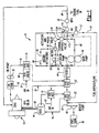
- Figure 1 shows a schematic representation of a fluid flow system 10 for a gas turbine engine 12. It should be understood that although the illustrated embodiment will refer to aircraft systems, sea, air, land and other vehicles will benefit from the instant invention.
- An Integrated Drive Generator System (IDGS) 14 is mechanically linked (illustrated schematically at 15) to the engine 12.
- the IDGS 14 is preferably a constant speed drive system which provides electrical power for the system 10 and other vehicle components.
- the IDGS 14 is cooled by an IDGS oil loop 16 wherein oil flowing from the IDGS 14 passes in sequence through a first IDG air-oil cooler 18 and a IDG fuel-oil cooler 20 before being returned to the IDGS 14.
- Cooling air (illustrated schematically by arrow 22) is extracted (bleed air) from the compressor or fan section of the engine 12 through the IDG air-oil cooler 18.
- Cooler refers to a heat exchanger device which alters the thermal properties of the fluid mediums flowing there through.
- Lubricating and cooling oil for the main engine bearings and other internal components of the engine 12 circulates in a second primary oil loop 24, passing in sequence from an oil storage tank 26, an oil pump 28, an engine air-oil cooler 30, and an engine fuel-oil cooler 32 before returning to the engine 12.
- Cooling air (illustrated schematically by arrow 34) for the engine air-oil cooler 30 is regulated by an air-oil cooler valve 36.
- the air-oil cooler valve 36 regulates the air into the air-oil cooler in a known manner.
- Boost pumps are typically centrifugal pumps designed to operate at an essentially constant pressure for a given engine speed, independent of the volumetric flow rate of fuel there through.
- Boost pump 40 supplies fuel to a fuel conduit 42 which communicates fuel through the aforementioned IDG fuel-oil cooler 20 and engine fuel-oil cooler 32. From the fuel-oil coolers 20,32 the fuel passes through a filter 44 and into a junction 46.
- combustion fuel is supplied to a main pump 48 and an actuator pump 50.
- the main pump is sized to provide engine burn flow.
- the pumps 48, 50 thus both receive fuel under low pressure from the common source.
- fuel is communicated through a main pump junction 52 which communicates with a thermal bypass valve (TBV) 54.
- TBV thermal bypass valve
- actuator pump 50 fuel is communicated through an actuator junction 56 where high pressure fuel is supplied through an actuator minimum pressure valve (AMPV) 58 and into the TBV 54.
- AMPV actuator minimum pressure valve
- the actuator junction 56 preferably includes a filter 57 to further filter the high pressure fuel supplied by the actuator pump 50 prior to entering an engine actuator (illustrated schematically at 60.)
- the actuators 60 are high pressure fluid actuators which operate engine components such as inlet guide vanes, bleed valves, turbine cooling valves, nozzle actuators and the like.
- the actuator pump 50 is preferably sized to provide actuator steady state plus transient flow to assure positive operation of the actuators 60. Most preferably, the actuator pump 50 provides fuel to the actuators 60 at a pressure (at least approximately 300 psi or 2 Mega Pascals) which is significantly higher than the main pump 48 pressure (at least approximately 100psi or 0.7 Mega Pascals.)
- the AMPV 58 regulates actuator pump 50 discharge pressure above an actuator pump inlet 62 pressure to the minimum pressure required to assure the positive operation of the actuators 60. That is, the AMPV 58 assures that the actuator flow pressure provided by the actuator pump 50 is always that which is required to operate the actuator 60. From the actuators 60 fuel is returned to the actuator pump inlet 62 through an actuator return conduit 64.
- the TBV determines the flow path of the excess fluid from the actuator pump 50.
- the TBV 54 selectively divides the fuel flow between being recirculated to the actuator pump inlet 62 and the main pump output flow path passing through main pump conduit 66 to join together in the engine fuel input conduit 68.
- the TBV 54 will recirculate the fuel to the actuator pump inlet 62 to raise the fuel temperature within the actuator fuel flow circuit without the heretofore-required servo heater.
- the engine actuators 60 are thereby assured of receiving flow which precludes freezing of water entrained in the fuel.
- the TBV 54 passes a greater percentage of fuel to the main pump conduit 66 to join together in the engine fuel input conduit 68.
- the AMPV 58 assures that the actuator flow pressure is always that which is required to operate the actuators 60. It should be understood that the TBV 54 may operate at a fixed and/or varied temperature or range of temperatures depending on engine operating condition and environment and is not to be limited to actuation at only a single temperature.
- a bypass flow conduit 70 recirculates excess fuel flow to the output of the boost pump 40.
- a Pressure Regulating Valve (PRV) 72 within the bypass flow conduit 70 senses a pressure drop across a metering valve (MV) 74.
- the MV 74 is preferably located in the engine fuel input conduit 68 after a junction 75 which provides for the bypass of excess main pump 48 and actuator pump 50 flow as required to maintain a constant metering valve (MV) 74 pressure drop.
- the Minimum Pressure Valve (MPV) 76 maintains a minimum pressure rise between the main pump inlet and the main pump discharge. Typically, at reduced flow conditions, the pressure required to deliver burn flow to the engine 12 is significantly less that that required by the actuators 60. As the actuator pump 50 provides high pressure to the actuators 60, the main pump is sized to provide engine burn flow and maintain proper operation of the main pump 48. The pressure rise is preferably set to be that which assures proper main pump 48 operation. That is, the main pump 50 and MPV 76 are relieved from the heretofore limitation of providing high pressure fuel to the actuators.
- the described embodiment properly schedules burn flow to the engine 12 while reducing the bypass flow through the bypass flow conduit 70. Less recirculation reduces the heating of the combustion fuel significantly reducing heat generation at low flow demand.
- the described embodiment thus reduces the necessity for the considerably heavy and cumbersome air/oil and fuel/oil coolers. The described embodiment thereby further benefits from lighter, smaller and/or less numerous coolers.
- bypass flow in the illustrated embodiment is a single flow path, other and/or multiple bypass flow paths to other upstream locations will also benefit from the present invention.
- an alternative or additional pressure relief valve could also divert bypass flow to the fuel conduit 42 between the fuel-oil coolers 20, 32.
- the system may additionally and or alternatively be implemented in a microprocessor based electronic actuation system (either digital or analog).
Landscapes
- Engineering & Computer Science (AREA)
- Chemical & Material Sciences (AREA)
- Combustion & Propulsion (AREA)
- Mechanical Engineering (AREA)
- General Engineering & Computer Science (AREA)
- Lubrication Of Internal Combustion Engines (AREA)
- Structures Of Non-Positive Displacement Pumps (AREA)
- Engine Equipment That Uses Special Cycles (AREA)
- Output Control And Ontrol Of Special Type Engine (AREA)
- Control Of Turbines (AREA)
- Temperature-Responsive Valves (AREA)
Abstract
Description
- The present invention relates to a system for transferring heat energy within a gas turbine engine, and more particularly to a system which provides an actuator pump to minimize the usage of heat exchangers.
- The fluid flow requirements of gas turbine engines are well known to the designers of today's high performance aircraft powerplants. Certain internal structures, such as bearings, are both cooled and lubricated by a circulating flow of oil which is distributed and collected throughout the main engine structure. Another thermal management method includes rejecting heat from the circulating oil loops into the flow of fuel entering the engine combustion chamber. This method uses the fuel flow as a recuperative heat sink which incurs few of the penalties of air cooling, but is limited in effectiveness by the maximum temperature tolerable by the fuel. Further effectiveness of using the flow of fuel, is the limitation necessitated by maintaining the fuel flow above freezing to minimize the possibility of ice formation and subsequent entry into sensitive areas such as engine actuators.
- Main fuel pumps for aircraft gas turbines have traditionally been fixed delivery, positive displacement type pumps connected mechanically to the rotating engine shaft. As the flow rate from a pump turning proportional to engine shaft speed cannot match the fuel flow requirements of a gas turbine engine operating under a variety of power levels, it is common to size the main fuel pump with an excess flow capacity under all engine operating conditions. The fuel system therefore include a fuel bypass for routing excess main fuel flow back to the low pressure side of the main pump. Such fluid flow system requirements results in complex thermal management requirements.
- Cooling oil circulating through the main engine lubrication system receives heat energy at a rate related to the product of engine rotor speed and power output. The cooling needs of the main engine lubrication loop are thus at a minimum during periods of low power operation, such as idling, and at a maximum during high or full power operation, such as takeoff.
- Under certain operating conditions, such as engine idling, the amount of fresh fuel entering the fuel system is small while the relative volume of fuel being bypassed back to the pump inlet is quite large. The combination of pump inefficiency and recirculation of excess fuel through the fuel bypass may heat the circulating fuel to an undesirably high temperature. This excess heat must be rejected to assure that the fuel remains within its maximum tolerable temperature.
- Excess heat is commonly managed by a combination of fuel/oil and air/oil heat exchangers. Such heat exchangers are undesirable because of their negative impact on engine efficiency, weight and expense. Thermal energy rejected from the engine oil does not contribute to engine thrust, while the majority of thermal energy rejected from the oil to the fuel is recovered at the engine burner stage. Additionally, cooling air for the air/oil coolers is typically bled from a cool high-pressure air source such as engine fan discharge which further reduces engine thrust.
- Conversely, other operating conditions result in insufficient fuel heating which may also become a concern. The fluid flow system must provide sufficient fuel heating to prevent entrained water from freezing and possibly blocking small openings in the fuel system actuator servos. For example, at certain high power conditions such as cold day takeoff, the heat available from the circulating lubricating oil is often insufficient to heat the high volume of relatively cold fuel to a temperature above freezing. A servo heater is commonly provided to assure the high pressure flow which operates the actuators will not freeze. Further negative impact on engine efficiency, weight and expense thus results.
- Accordingly, it is desirable to provide a fluid flow system for a gas turbine engine which significantly reduces heat generation at low flow demand to minimize the size and number of heat exchangers. It is further desirable to regulate actuator flow temperature at high fluid flows to preclude freezing of water entrained in the fuel.
- The fluid flow system for a gas turbine engine according to the present invention comprises a main pump in fluid communication with a thermal bypass valve; and an actuator pump in fluid communication with said thermal bypass valve such that an excess actuator fluid flow from said actuator pump is directed to said thermal bypass valve. In preferred embodiments, from the actuator pump, fuel is communicated through an actuator junction where high pressure fuel is supplied to an actuator minimum pressure valve (AMPV) and into a Thermal Bypass Valve (TBV.) The actuator junction preferably includes a filter to further filter the high pressure fuel prior to entering an engine actuator. Engine actuators may be high pressure fluid actuators which operate engine components such as inlet guide vanes, bleed valves, turbine cooling valves, nozzle actuators and the like.
- The actuator pump is preferably sized to provide actuator steady state plus transient flow to assure positive operation of the actuators. The AMPV regulates actuator pump discharge pressure above actuator pump inlet pressure to the minimum pressure required to assure the positive operation of the actuators. That is, the AMPV assures that the actuator flow pressure provided by the actuator pump is that which is required to operate the actuator.
- Fuel flow from the actuator pump in excess of the actuators needs is directed through the AMPV and into the TBV. Depending upon the temperature of the fuel, the TBV determines the path of the excess actuator pump fluid flow. The TBV divides the fuel flow between being recirculated to the actuator pump inlet and the main pump output flow path to the engine fuel input conduit. Preferably, when the fuel is near the freezing point of water, the TBV will recirculate the fuel to the actuator pump inlet to raise the fuel temperature within the actuator fuel flow circuit without the heretofore-required servo heater. The engine actuators are thereby assured of receiving flow which precludes freezing of water entrained in the fuel. When there is minimal concern with the possibility of freezing water entrained in the fuel, the TBV passes a greater percentage of fuel through to join together in the engine fuel input conduit. The AMPV assures that the actuator flow pressure is always that which is required to operate the actuators.
- The present invention therefore provides, in at least its preferred embodiments, a fluid flow system for a gas turbine engine which significantly reduces heat generation at low flow demand to minimize the demand for heat exchangers while regulating actuator flow temperature at high fluid flows to preclude freezing of water entrained in the fuel.
- The various features and advantages of this invention will become apparent to those skilled in the art from the following detailed description of the currently preferred embodiment. The drawing that accompanies the detailed description can be briefly described as follows:
- Figure 1 is a schematic representation of a fuel and oil flow system according to the present invention.
-
- Figure 1 shows a schematic representation of a
fluid flow system 10 for agas turbine engine 12. It should be understood that although the illustrated embodiment will refer to aircraft systems, sea, air, land and other vehicles will benefit from the instant invention. - An Integrated Drive Generator System (IDGS) 14 is mechanically linked (illustrated schematically at 15) to the
engine 12. The IDGS 14 is preferably a constant speed drive system which provides electrical power for thesystem 10 and other vehicle components. The IDGS 14 is cooled by an IDGSoil loop 16 wherein oil flowing from the IDGS 14 passes in sequence through a first IDG air-oil cooler 18 and a IDG fuel-oil cooler 20 before being returned to the IDGS 14. Cooling air (illustrated schematically by arrow 22) is extracted (bleed air) from the compressor or fan section of theengine 12 through the IDG air-oil cooler 18. It should be understood that other air sources such as a RAM air source will also benefit from the present invention. It should be further understood that the term "cooler" refers to a heat exchanger device which alters the thermal properties of the fluid mediums flowing there through. - Lubricating and cooling oil for the main engine bearings and other internal components of the
engine 12 circulates in a secondprimary oil loop 24, passing in sequence from anoil storage tank 26, anoil pump 28, an engine air-oil cooler 30, and an engine fuel-oil cooler 32 before returning to theengine 12. Cooling air (illustrated schematically by arrow 34) for the engine air-oil cooler 30 is regulated by an air-oil cooler valve 36. The air-oil cooler valve 36 regulates the air into the air-oil cooler in a known manner. - Combustion fuel is supplied to the engine from the
main fuel tank 38 by an engine drivenboost pump 40. Boost pumps are typically centrifugal pumps designed to operate at an essentially constant pressure for a given engine speed, independent of the volumetric flow rate of fuel there through.Boost pump 40 supplies fuel to afuel conduit 42 which communicates fuel through the aforementioned IDG fuel-oil cooler 20 and engine fuel-oil cooler 32. From the fuel-oil coolers 20,32 the fuel passes through afilter 44 and into ajunction 46. - From the
junction 46, combustion fuel is supplied to amain pump 48 and anactuator pump 50. The main pump is sized to provide engine burn flow. Thepumps main pump 48, fuel is communicated through amain pump junction 52 which communicates with a thermal bypass valve (TBV) 54. From theactuator pump 50, fuel is communicated through anactuator junction 56 where high pressure fuel is supplied through an actuator minimum pressure valve (AMPV) 58 and into theTBV 54. - The
actuator junction 56 preferably includes afilter 57 to further filter the high pressure fuel supplied by theactuator pump 50 prior to entering an engine actuator (illustrated schematically at 60.) Theactuators 60 are high pressure fluid actuators which operate engine components such as inlet guide vanes, bleed valves, turbine cooling valves, nozzle actuators and the like. Theactuator pump 50 is preferably sized to provide actuator steady state plus transient flow to assure positive operation of theactuators 60. Most preferably, theactuator pump 50 provides fuel to theactuators 60 at a pressure (at least approximately 300 psi or 2 Mega Pascals) which is significantly higher than themain pump 48 pressure (at least approximately 100psi or 0.7 Mega Pascals.) - The
AMPV 58 regulatesactuator pump 50 discharge pressure above anactuator pump inlet 62 pressure to the minimum pressure required to assure the positive operation of theactuators 60. That is, theAMPV 58 assures that the actuator flow pressure provided by theactuator pump 50 is always that which is required to operate theactuator 60. From theactuators 60 fuel is returned to theactuator pump inlet 62 through anactuator return conduit 64. - Fuel flow from the
actuator pump 50 in excess of theactuators 60 needs is directed through theAMPV 58 and into theTBV 54. Depending upon the temperature of the fuel, the TBV determines the flow path of the excess fluid from theactuator pump 50. TheTBV 54 selectively divides the fuel flow between being recirculated to theactuator pump inlet 62 and the main pump output flow path passing throughmain pump conduit 66 to join together in the enginefuel input conduit 68. Preferably, when the fuel is near the freezing point of water, theTBV 54 will recirculate the fuel to theactuator pump inlet 62 to raise the fuel temperature within the actuator fuel flow circuit without the heretofore-required servo heater. The engine actuators 60 are thereby assured of receiving flow which precludes freezing of water entrained in the fuel. When there is minimal concern with the possibility of freezing water entrained in the fuel, theTBV 54 passes a greater percentage of fuel to themain pump conduit 66 to join together in the enginefuel input conduit 68. TheAMPV 58 assures that the actuator flow pressure is always that which is required to operate theactuators 60. It should be understood that theTBV 54 may operate at a fixed and/or varied temperature or range of temperatures depending on engine operating condition and environment and is not to be limited to actuation at only a single temperature. - A
bypass flow conduit 70 recirculates excess fuel flow to the output of theboost pump 40. A Pressure Regulating Valve (PRV) 72 within thebypass flow conduit 70 senses a pressure drop across a metering valve (MV) 74. TheMV 74 is preferably located in the enginefuel input conduit 68 after ajunction 75 which provides for the bypass of excessmain pump 48 andactuator pump 50 flow as required to maintain a constant metering valve (MV) 74 pressure drop. - The Minimum Pressure Valve (MPV) 76 maintains a minimum pressure rise between the main pump inlet and the main pump discharge. Typically, at reduced flow conditions, the pressure required to deliver burn flow to the
engine 12 is significantly less that that required by theactuators 60. As theactuator pump 50 provides high pressure to theactuators 60, the main pump is sized to provide engine burn flow and maintain proper operation of themain pump 48. The pressure rise is preferably set to be that which assures propermain pump 48 operation. That is, themain pump 50 andMPV 76 are relieved from the heretofore limitation of providing high pressure fuel to the actuators. - The described embodiment properly schedules burn flow to the
engine 12 while reducing the bypass flow through thebypass flow conduit 70. Less recirculation reduces the heating of the combustion fuel significantly reducing heat generation at low flow demand. The described embodiment thus reduces the necessity for the considerably heavy and cumbersome air/oil and fuel/oil coolers. The described embodiment thereby further benefits from lighter, smaller and/or less numerous coolers. - It should be understood that although the bypass flow in the illustrated embodiment is a single flow path, other and/or multiple bypass flow paths to other upstream locations will also benefit from the present invention. For example, an alternative or additional pressure relief valve could also divert bypass flow to the
fuel conduit 42 between the fuel-oil coolers 20, 32. - Furthermore, while it is obvious it still is worth stating that the present invention is clearly not limited to a manual valve control. The system may additionally and or alternatively be implemented in a microprocessor based electronic actuation system (either digital or analog).
- The foregoing description is exemplary rather than defined by the limitations within. Many modifications and variations of the present invention are possible in light of the above teachings. The preferred embodiments of this invention have been disclosed, however, one of ordinary skill in the art would recognize that certain modifications would come within the scope of this invention. It is, therefore, to be understood that within the scope of the appended claims, the invention may be practiced otherwise than as specifically described. For that reason the following claims should be studied to determine the true scope and content of this invention.
Claims (20)
- A fluid flow system (10) for a gas turbine engine (12) comprising:a main pump (48) in fluid communication with a thermal bypass valve (54); andan actuator pump (50) in fluid communication with said thermal bypass valve (54) such that an excess actuator fluid flow from said actuator pump (50) is directed to said thermal bypass valve (54).
- The fluid flow system (10) as recited in claim 1, further including an actuator minimum pressure valve (58) which communicates with said actuator pump (50) and said thermal bypass valve (54).
- The fluid flow system (10) as recited in claim 2, further including an actuator (60), said actuator minimum pressure valve (58) directing at least a portion of an actuator fluid flow from said actuator pump (50) to said actuator (60).
- The fluid flow system (10) as recited in claim 1, 2 or 3, wherein said thermal bypass valve (54) selectively directs at least a portion of the actuator fluid flow to an actuator pump inlet (62) and a main fluid flow path (66) from said main pump (48).
- The fluid flow system (10) as recited in claim 4, wherein said thermal bypass valve (54) directs at least a portion of said actuator fluid flow to said main fluid flow path (66) at temperatures above zero degrees Centigrade.
- The fluid flow system (10) as recited in any preceding claim, wherein said actuator pump (50) operates at approximately 2 Mega Pascals.
- The fluid flow system (10) as recited in any preceding claim, wherein said main pump (48) operates at approximately 0.7 Mega Pascals.
- A fluid flow system (10) for a gas turbine engine (12) comprising:a main pump (48) in fluid communication with a thermal bypass valve (54); an actuator pump (50) in fluid communication with an engine actuator (60) and said thermal bypass valve (54); andan actuator minimum pressure valve (58) in fluid communication with said actuator pump (50) and said thermal bypass valve (54), actuator fluid flow from said actuator pump (50) in excess of said actuator (60) requirements being directed to said thermal bypass valve (54).
- The fluid flow system (10) as recited in claim 8, wherein flow (64) from said actuator (60) is directed to an actuator pump inlet (62).
- The fluid flow system (10) as recited in claim 8 or 9, wherein said thermal bypass valve (54) selectively directs fluid flow to an actuator pump inlet (62) and a main fluid flow path (66) from said main pump (48).
- The fluid flow system (10) as recited in claim 8, 9 or 10, further including a source (38,40) to provide fluid flow to a main pump inlet and an actuator pump inlet.
- The fluid flow system as recited in claim 11, further including a pressure regulating valve (72) within a main flow path (70) from said main pump (48) to bypass excess actuator fluid flow and main pump fluid flow upstream of said main pump inlet and said actuator pump inlet (62).
- The fluid flow system (10) as recited in claim 12, further including a metering valve (74) within said main flow path (78) such that said pressure regulating valve (72) is operable to sense a pressure drop across said metering valve (74).
- The fluid flow system as recited in any of claims 8 to 13, wherein said engine actuator (60) includes a turbine cooling valve.
- The fluid flow system as recited in any of claims 8 to 14, wherein said engine actuator (60) includes a engine nozzle actuator.
- The fluid flow system as recited in any of claims 8 to 15, wherein said thermal bypass valve (54) directs at least a portion of said actuator fluid flow to a main fluid flow path (66) at temperatures above zero degrees Centigrade.
- A method of controlling a fluid flow system (10) for a gas turbine engine (12) comprising the steps of:(1) dividing fluid flow from a source (38,40) between a relatively high pressure source (50) and a relatively low pressure source (48);(2) communicating a low pressure output from the low pressure source (48) and a high pressure output from the high pressure source (50) with a thermally dependent device (54); and(3) selectively directing at least a portion of said high pressure output from the thermally dependent device (54) between an input (62) of the high pressure source and a main fluid flow path (66) in communication with the low pressure output.
- A method as recited in claim 17, wherein said step (2) includes communicating at least a portion of the high pressure output to an actuator (60) operable by the flow of the high pressure output.
- A method as recited in claim 18, wherein the portion of the high pressure output to the actuator (60) is always maintained above a predetermined pressure.
- A method as recited in claim 17, wherein said step (3) is dependent upon assuring said high pressure output is maintained above a predetermined temperature.
Applications Claiming Priority (2)
| Application Number | Priority Date | Filing Date | Title |
|---|---|---|---|
| US10/054,480 US6651441B2 (en) | 2002-01-22 | 2002-01-22 | Fluid flow system for a gas turbine engine |
| US54480 | 2002-01-22 |
Publications (3)
| Publication Number | Publication Date |
|---|---|
| EP1329617A2 true EP1329617A2 (en) | 2003-07-23 |
| EP1329617A3 EP1329617A3 (en) | 2005-04-27 |
| EP1329617B1 EP1329617B1 (en) | 2007-03-14 |
Family
ID=21991373
Family Applications (1)
| Application Number | Title | Priority Date | Filing Date |
|---|---|---|---|
| EP03250392A Expired - Lifetime EP1329617B1 (en) | 2002-01-22 | 2003-01-22 | Fluid flow system for a gas turbine engine |
Country Status (4)
| Country | Link |
|---|---|
| US (1) | US6651441B2 (en) |
| EP (1) | EP1329617B1 (en) |
| JP (1) | JP4195308B2 (en) |
| DE (1) | DE60312405T2 (en) |
Cited By (22)
| Publication number | Priority date | Publication date | Assignee | Title |
|---|---|---|---|---|
| US6939392B2 (en) | 2003-04-04 | 2005-09-06 | United Technologies Corporation | System and method for thermal management |
| EP1983174A2 (en) * | 2007-04-17 | 2008-10-22 | Rolls-Royce plc | Apparatus and method of operating a gas turbine engine at start-up |
| FR2925110A1 (en) * | 2007-12-13 | 2009-06-19 | Hispano Suiza Sa | Oil supplying device for turboshaft engine of airplane, has oil supply unit with start-up assistance pump which provides power to allow functioning of starters/generators, where start-up assistance pump is placed in parallel to main pump |
| FR2925594A1 (en) * | 2007-12-20 | 2009-06-26 | Hispano Suiza Sa | SYSTEM FOR CONTROLLING A TURBOMACHINE |
| WO2009140100A1 (en) * | 2008-05-13 | 2009-11-19 | General Electric Company | Method and apparatus for controlling fuel in a gas turbine engine |
| EP2136050A2 (en) * | 2007-09-06 | 2009-12-23 | Open Joint Stock Company "Russian Railways" | Gas turbine plant |
| EP1923542A3 (en) * | 2006-11-09 | 2010-01-20 | United Technologies Corporation | Interdependant lubrication systems |
| FR2935749A1 (en) * | 2008-09-11 | 2010-03-12 | Hispano Suiza Sa | Fuel circuit for use in jet engine of airplane, has hydraulic cylinders supplied with fuel through servo valves, and fuel line including electrical fuel heating device arranged in upstream of servo valves |
| WO2012093235A1 (en) * | 2011-01-06 | 2012-07-12 | Snecma | Fuel circuit of an aeronautical turbine engine having a fuel pressure regulating valve |
| EP2500552A3 (en) * | 2011-03-18 | 2013-04-17 | Hamilton Sundstrand Corporation | Dual pump fuel flow system for a gas turbine engine and method of controlling |
| EP2500551A3 (en) * | 2011-03-18 | 2013-04-17 | Hamilton Sundstrand Corporation | Fuel flow control system and method for controlling two positive displacement pumps |
| WO2014013201A1 (en) * | 2012-07-20 | 2014-01-23 | Snecma | Device for the transfer of heat between a lubrication pipe and a turbomachine blade pitch actuator control hydraulic pipe |
| CN102365441B (en) * | 2009-03-25 | 2014-02-12 | 伍德沃德公司 | Variable actuation pressure system for independent pressure control |
| EP2837798A1 (en) * | 2013-08-14 | 2015-02-18 | Hamilton Sundstrand Corporation | Heated bypass valve for heat exchanger |
| EP2784270A3 (en) * | 2013-03-27 | 2015-04-29 | Hamilton Sundstrand Corporation | Fuel and actuation system for gas turbine engine |
| WO2016048787A1 (en) * | 2014-09-23 | 2016-03-31 | Woodward, Inc. | Pump authority switching apparatus for a fluid distribution system |
| EP2809916A4 (en) * | 2012-01-31 | 2016-08-03 | United Technologies Corp | Gas turbine engine with geared turbofan and oil thermal management system with unique heat exchanger structure |
| US9500135B2 (en) * | 2009-10-06 | 2016-11-22 | Snecma | Fuel feed circuit for an aeroengine having a high pressure pump system with two pumps |
| EP3179075A1 (en) * | 2015-12-08 | 2017-06-14 | General Electric Company | Thermal management system for a gas turbine |
| EP2778371A3 (en) * | 2013-03-14 | 2017-08-02 | Hamilton Sundstrand Corporation | Engine manifold drain system |
| CN108071494A (en) * | 2016-11-15 | 2018-05-25 | 通用电气公司 | For passively control fuel flow to gas turbine axial fuel grade automatic thermal valve |
| US10107198B2 (en) | 2013-01-21 | 2018-10-23 | United Technologies Corporation | Gas turbine engine with geared turbofan and oil thermal management system with unique heat exchanger structure |
Families Citing this family (52)
| Publication number | Priority date | Publication date | Assignee | Title |
|---|---|---|---|---|
| US7434765B2 (en) * | 2005-02-16 | 2008-10-14 | The Boeing Company | Heat exchanger systems and associated systems and methods for cooling aircraft starter/generators |
| US7908840B2 (en) * | 2006-11-29 | 2011-03-22 | United Technologies Corporation | Turbine engine with integrated generator having shared lubrication system |
| US9234481B2 (en) * | 2008-01-25 | 2016-01-12 | United Technologies Corporation | Shared flow thermal management system |
| US8826641B2 (en) * | 2008-01-28 | 2014-09-09 | United Technologies Corporation | Thermal management system integrated pylon |
| US8256222B2 (en) * | 2008-02-11 | 2012-09-04 | Honeywell International Inc. | Direct metering fuel control with integral electrical metering pump and actuator servo pump |
| US8302406B2 (en) * | 2008-10-15 | 2012-11-06 | Woodward, Inc. | Fuel delivery and control system including a positive displacement actuation pump with a variable pressure regulator supplementing a fixed displacement main fuel pump |
| US8166765B2 (en) * | 2008-10-15 | 2012-05-01 | Woodward, Inc. | Fuel delivery and control system including a variable displacement actuation pump supplementing a fixed displacement main pump |
| US20100313591A1 (en) * | 2009-06-12 | 2010-12-16 | Hamilton Sundstrand Corporation | Adaptive heat sink for aircraft environmental control system |
| US8264100B2 (en) * | 2009-09-11 | 2012-09-11 | Hamilton Sundstrand Corporation | Electric power generating system for multiple sources and interface to an AC grid |
| US8793971B2 (en) * | 2010-05-25 | 2014-08-05 | Hamilton Sundstrand Corporation | Fuel pumping system for a gas turbine engine |
| US8536729B2 (en) | 2010-06-09 | 2013-09-17 | Hamilton Sundstrand Corporation | Hybrid electric power architecture for a vehicle |
| DE202010011010U1 (en) * | 2010-08-04 | 2010-11-04 | Bucyrus Hex Gmbh | Hydraulic preheater for hydraulic oil cooler in a large hydraulic excavator |
| US8319517B2 (en) * | 2010-08-25 | 2012-11-27 | Hamilton Sundstrand Corporation | Generator tester |
| US8708243B2 (en) | 2010-10-19 | 2014-04-29 | Hs Marston Aerospace Ltd. | Thermal valve |
| FR2971548B1 (en) * | 2011-02-11 | 2015-02-13 | Snecma | FUEL SUPPLY SYSTEM WITH MULTIPLE PUMPING MEANS |
| US8869509B2 (en) | 2011-06-09 | 2014-10-28 | Woodward, Inc. | Accessory flow recovery system and method for thermal efficient pump and control system |
| US9080511B2 (en) | 2011-10-21 | 2015-07-14 | United Technologies Corporation | Integrated thermal system for a gas turbine engine |
| US8978351B2 (en) * | 2011-10-21 | 2015-03-17 | United Technologies Corporation | Integrated thermal management system and environmental control system for a gas turbine engine |
| US9200569B2 (en) * | 2011-10-21 | 2015-12-01 | United Technologies Corporation | Compartment cooling for a gas turbine engine |
| US8966875B2 (en) * | 2011-10-21 | 2015-03-03 | United Technologies Corporation | Constant speed transmission for gas turbine engine |
| US8257024B1 (en) | 2012-01-27 | 2012-09-04 | United Technologies Corporation | Geared turbomachine fluid delivery system |
| US8443582B1 (en) | 2012-01-31 | 2013-05-21 | United Technologies Corporation | Gas turbine engine with geared turbofan and oil thermal management system |
| US9206775B2 (en) | 2012-02-01 | 2015-12-08 | United Technologies Corporation | Fuel preheating using electric pump |
| US9316157B2 (en) | 2012-02-01 | 2016-04-19 | Hamilton Sundstrand Corporation | Fuel system for starting an APU using a hybrid pump arrangement |
| US9222415B2 (en) | 2012-03-06 | 2015-12-29 | Hamilton Sundstrand Corporation | Gas turbine engine fuel heating system |
| US9328835B2 (en) | 2012-10-23 | 2016-05-03 | Hamilton Sundstrand Corporation | High pressure relief valve piston |
| US9175789B2 (en) | 2012-10-23 | 2015-11-03 | Hamilton Sundstrand Corporation | Pressure regulating valve |
| US9856794B2 (en) | 2012-10-23 | 2018-01-02 | Hamilton Sundstrand Corporation | High pressure relief valve nozzle |
| US9038662B2 (en) | 2012-10-23 | 2015-05-26 | Hamilton Sunstrand Corporation | High pressure relief valve spring assembly |
| US9791058B2 (en) | 2012-10-23 | 2017-10-17 | Hamilton Sundstrand Corporation | High pressure relief valve closure |
| US8776835B2 (en) | 2012-12-05 | 2014-07-15 | Hamilton Sundstrand Corporation | Fluid duct with improved connecting bead |
| US10350521B2 (en) | 2013-01-15 | 2019-07-16 | United Technologies Corporation | Fuel system ice and debris separator (IDS) with partial filter screen and torturous path |
| WO2014200587A2 (en) * | 2013-01-21 | 2014-12-18 | United Technologies Corporation | Air oil cooler airflow augmentation system |
| US11105267B2 (en) * | 2013-02-21 | 2021-08-31 | Raytheon Technologies Corporation | Removing non-homogeneous ice from a fuel system |
| BR112015024588A2 (en) * | 2013-04-14 | 2017-07-18 | Gen Electric | engine overspeed protection systems |
| US9140191B2 (en) | 2013-04-22 | 2015-09-22 | Hamilton Sundstrand Corporation | System for controlling two positive displacement pumps |
| EP3008311A4 (en) * | 2013-06-12 | 2016-07-20 | United Technologies Corp | Fuel/oil manifold |
| US9388778B2 (en) * | 2013-07-19 | 2016-07-12 | Woodward, Inc. | Servo flow recirculation for an advanced thermal efficient aircraft engine fuel system |
| FR3028245B1 (en) * | 2014-11-06 | 2019-05-24 | Airbus Operations | FUEL SUPPLY CIRCUIT OF AN AIRCRAFT |
| US9512783B2 (en) * | 2014-11-14 | 2016-12-06 | Hamilton Sundstrand Corporation | Aircraft fuel system |
| US10066507B1 (en) * | 2015-02-10 | 2018-09-04 | United Technologies Corporation | Turbine engine lubrication system with wash flow filter |
| US10125732B1 (en) * | 2015-02-23 | 2018-11-13 | Eaton Intelligent Power Limited | Hydromechanical fuel system with dual bypass |
| FR3042818B1 (en) * | 2015-10-23 | 2021-12-03 | Snecma | FLUID RECIRCULATION THROUGH A TURBOMACHINE CENTRIFUGAL PUMP |
| US10323540B2 (en) | 2015-12-07 | 2019-06-18 | General Electric Company | Gas turbine engine fluid cooling systems and methods of assembling the same |
| US10697371B2 (en) * | 2015-12-28 | 2020-06-30 | General Electric Company | Method and system for a combined air-oil cooler and fuel-oil cooler heat exchanger |
| US10502138B2 (en) | 2016-04-11 | 2019-12-10 | Hamilton Sundstrand Corporation | Dual pump fuel system with pump sharing connection |
| US20180050812A1 (en) * | 2016-08-16 | 2018-02-22 | Hamilton Sundstrand Corporation | Aircraft fuel pump systems |
| US11028775B2 (en) * | 2018-08-23 | 2021-06-08 | The Boeing Company | Bleed air boosted engine oil cooler |
| US11203978B2 (en) * | 2020-01-20 | 2021-12-21 | Hamilton Sundstrand Corporation | Dual pump unit with boost pump |
| GB2599686A (en) * | 2020-10-09 | 2022-04-13 | Rolls Royce Plc | An improved turbofan gas turbine engine |
| US20220195927A1 (en) * | 2020-12-21 | 2022-06-23 | General Electric Company | Regenerative fuel heating system |
| US11708795B1 (en) * | 2022-07-05 | 2023-07-25 | Hamilton Sundstrand Corporation | Systems and methods for bleed valve control in fuel systems |
Citations (6)
| Publication number | Priority date | Publication date | Assignee | Title |
|---|---|---|---|---|
| US3332234A (en) * | 1966-03-24 | 1967-07-25 | John P Lavash | Fuel delivery systems |
| US3442218A (en) * | 1966-04-12 | 1969-05-06 | Gen Electric | Dual purpose pump |
| US3899877A (en) * | 1973-07-02 | 1975-08-19 | Gen Motors Corp | Gas turbine engine power shift transmission power train |
| US4354345A (en) * | 1980-04-29 | 1982-10-19 | United Technologies Corporation | Fuel heating system for gas turbine engine |
| US4607486A (en) * | 1983-12-02 | 1986-08-26 | United Technologies Corporation | Centrifugal main fuel pump |
| US5116362A (en) * | 1990-12-03 | 1992-05-26 | United Technologies Corporation | Fuel metering and actuation system |
Family Cites Families (26)
| Publication number | Priority date | Publication date | Assignee | Title |
|---|---|---|---|---|
| US4151710A (en) | 1977-03-11 | 1979-05-01 | United Technologies Corporation | Lubrication cooling system for aircraft engine accessory |
| GB2111128B (en) | 1981-12-10 | 1984-10-17 | Rolls Royce | Fuel/oil heat exchange system for a gas turbine engine |
| GB2142391B (en) | 1983-07-01 | 1986-03-26 | Honda Motor Co Ltd | Control device for a direct clutch in automatic transmission |
| US4696156A (en) | 1986-06-03 | 1987-09-29 | United Technologies Corporation | Fuel and oil heat management system for a gas turbine engine |
| US4809499A (en) | 1987-03-20 | 1989-03-07 | United Technologies Corporation | Densimeter |
| US4876880A (en) | 1987-03-20 | 1989-10-31 | United Technologies Corporation | Densimeter |
| FR2619417B1 (en) * | 1987-08-12 | 1989-12-01 | Snecma | FUEL DISTRIBUTION CIRCUIT WITH INCREASED FUEL COOLING |
| US4910956A (en) * | 1988-04-28 | 1990-03-27 | United Technologies Corporation | Gas turbine overtemperature protection |
| US5159808A (en) | 1990-07-09 | 1992-11-03 | General Electric Company | Gas turbine engine fuel and hydraulic fluid pumping system |
| US5156332A (en) | 1991-09-24 | 1992-10-20 | United Technologies Corporation | Pressure regulating flow control apparatus |
| US5339636A (en) | 1992-12-04 | 1994-08-23 | United Technologies Corporation | Fuel splitter valve assembly for gas turbine |
| US5313790A (en) | 1992-12-17 | 1994-05-24 | Alliedsignal Inc. | Endothermic fluid based thermal management system |
| DE69402206T2 (en) | 1993-08-03 | 1997-10-09 | United Technologies Corp | CENTRIFUGAL PUMP WITH OUTLET |
| GB2282186B (en) | 1993-09-08 | 1997-09-24 | Rolls Royce Plc | Engine fuel metering system |
| US5442922A (en) | 1993-12-09 | 1995-08-22 | United Technologies Corporation | Fuel staging system |
| US5448882A (en) | 1993-12-14 | 1995-09-12 | United Technologies Corporation | Fuel metering system |
| US5715674A (en) | 1995-12-22 | 1998-02-10 | United Technologies Corporation | Hydromechanical control for a variable delivery, positive displacement fuel pump |
| US5702229A (en) | 1996-10-08 | 1997-12-30 | Walbro Corporation | Regenerative fuel pump |
| US5896737A (en) | 1997-06-16 | 1999-04-27 | United Technologies Corporation | Combined pressure regulating and fuel flow system |
| US6059537A (en) | 1997-11-13 | 2000-05-09 | Sundstrand Corporation | Aircraft fuel pump with centrifugal pump and regenerative pump stages |
| US6022197A (en) | 1997-11-14 | 2000-02-08 | Sundstrand Corporation | Aircraft pump system with internal pressure control, comprising a regenerative pump and a centrifugal pump |
| EP1045964B1 (en) | 1998-01-08 | 2012-08-08 | United Technologies Corporation | Bi-level hydraulic pressurizing system |
| FR2788561B1 (en) | 1999-01-14 | 2001-02-16 | Snecma | FUEL SYSTEM WITH PROTECTED MAIN FILTER |
| US6250894B1 (en) | 1999-04-07 | 2001-06-26 | United Technologies Corporation | Load sharing valve and system for operating centrifugal pumps in parallel |
| US6189313B1 (en) * | 1999-04-16 | 2001-02-20 | Hamilton Sundstrand Corporation | Aircraft engine fuel system mounting assembly |
| US6487847B1 (en) * | 2000-11-03 | 2002-12-03 | General Electric Company | Gas turbine engine fuel control system |
-
2002
- 2002-01-22 US US10/054,480 patent/US6651441B2/en not_active Expired - Lifetime
-
2003
- 2003-01-22 JP JP2003013220A patent/JP4195308B2/en not_active Expired - Fee Related
- 2003-01-22 EP EP03250392A patent/EP1329617B1/en not_active Expired - Lifetime
- 2003-01-22 DE DE60312405T patent/DE60312405T2/en not_active Expired - Lifetime
Patent Citations (6)
| Publication number | Priority date | Publication date | Assignee | Title |
|---|---|---|---|---|
| US3332234A (en) * | 1966-03-24 | 1967-07-25 | John P Lavash | Fuel delivery systems |
| US3442218A (en) * | 1966-04-12 | 1969-05-06 | Gen Electric | Dual purpose pump |
| US3899877A (en) * | 1973-07-02 | 1975-08-19 | Gen Motors Corp | Gas turbine engine power shift transmission power train |
| US4354345A (en) * | 1980-04-29 | 1982-10-19 | United Technologies Corporation | Fuel heating system for gas turbine engine |
| US4607486A (en) * | 1983-12-02 | 1986-08-26 | United Technologies Corporation | Centrifugal main fuel pump |
| US5116362A (en) * | 1990-12-03 | 1992-05-26 | United Technologies Corporation | Fuel metering and actuation system |
Cited By (46)
| Publication number | Priority date | Publication date | Assignee | Title |
|---|---|---|---|---|
| US6939392B2 (en) | 2003-04-04 | 2005-09-06 | United Technologies Corporation | System and method for thermal management |
| EP1677888A1 (en) * | 2003-09-08 | 2006-07-12 | United Technologies Corporation | System and method for thermal management |
| EP1677888A4 (en) * | 2003-09-08 | 2008-12-17 | United Technologies Corp | System and method for thermal management |
| EP1923542A3 (en) * | 2006-11-09 | 2010-01-20 | United Technologies Corporation | Interdependant lubrication systems |
| US8205427B2 (en) | 2006-11-09 | 2012-06-26 | United Technologies Corporation | Interdependent lubrication systems in a turbine engine |
| EP1983174A2 (en) * | 2007-04-17 | 2008-10-22 | Rolls-Royce plc | Apparatus and method of operating a gas turbine engine at start-up |
| EP1983174A3 (en) * | 2007-04-17 | 2012-12-19 | Rolls-Royce plc | Apparatus and method of operating a gas turbine engine at start-up |
| EP2136050A4 (en) * | 2007-09-06 | 2010-09-22 | Open Joint Stock Company Russi | Gas turbine plant |
| KR101168111B1 (en) | 2007-09-06 | 2012-07-24 | 오픈 조인트 스탁 컴퍼니 “러시안 레일웨이즈” | Gas turbine system |
| EP2136050A2 (en) * | 2007-09-06 | 2009-12-23 | Open Joint Stock Company "Russian Railways" | Gas turbine plant |
| FR2925110A1 (en) * | 2007-12-13 | 2009-06-19 | Hispano Suiza Sa | Oil supplying device for turboshaft engine of airplane, has oil supply unit with start-up assistance pump which provides power to allow functioning of starters/generators, where start-up assistance pump is placed in parallel to main pump |
| US8196385B2 (en) | 2007-12-20 | 2012-06-12 | Hispano Suiza | Turbomachine control system |
| FR2925594A1 (en) * | 2007-12-20 | 2009-06-26 | Hispano Suiza Sa | SYSTEM FOR CONTROLLING A TURBOMACHINE |
| GB2473555A (en) * | 2008-05-13 | 2011-03-16 | Gen Electric | Method and apparatus for controlling fuel in a gas turbine engine |
| GB2473555B (en) * | 2008-05-13 | 2012-06-20 | Gen Electric | Thermal management of fuel in gas turbine engines |
| WO2009140100A1 (en) * | 2008-05-13 | 2009-11-19 | General Electric Company | Method and apparatus for controlling fuel in a gas turbine engine |
| FR2935749A1 (en) * | 2008-09-11 | 2010-03-12 | Hispano Suiza Sa | Fuel circuit for use in jet engine of airplane, has hydraulic cylinders supplied with fuel through servo valves, and fuel line including electrical fuel heating device arranged in upstream of servo valves |
| CN102365441B (en) * | 2009-03-25 | 2014-02-12 | 伍德沃德公司 | Variable actuation pressure system for independent pressure control |
| US9500135B2 (en) * | 2009-10-06 | 2016-11-22 | Snecma | Fuel feed circuit for an aeroengine having a high pressure pump system with two pumps |
| GB2501198B (en) * | 2011-01-06 | 2017-03-22 | Snecma | A fuel circuit for an aviation turbine engine, the circuit having a fuel pressure regulator valve |
| GB2501198A (en) * | 2011-01-06 | 2013-10-16 | Snecma | Fuel circuit of an aeronautical turbine engine having a fuel pressure regulating valve |
| WO2012093235A1 (en) * | 2011-01-06 | 2012-07-12 | Snecma | Fuel circuit of an aeronautical turbine engine having a fuel pressure regulating valve |
| FR2970303A1 (en) * | 2011-01-06 | 2012-07-13 | Snecma | AERONAUTICAL TURBOMACHINE FUEL SYSTEM WITH FUEL PRESSURE CONTROL VALVE |
| US9702301B2 (en) | 2011-01-06 | 2017-07-11 | Snecma | Fuel circuit for an aviation turbine engine, the circuit having a fuel pressure regulator valve |
| EP2500552B1 (en) | 2011-03-18 | 2017-06-28 | Hamilton Sundstrand Corporation | Dual pump fuel flow system for a gas turbine engine and method of controlling |
| EP2500551B1 (en) | 2011-03-18 | 2017-06-28 | Hamilton Sundstrand Corporation | Fuel flow control system and method for controlling two positive displacement pumps |
| EP2500552A3 (en) * | 2011-03-18 | 2013-04-17 | Hamilton Sundstrand Corporation | Dual pump fuel flow system for a gas turbine engine and method of controlling |
| US8893466B2 (en) | 2011-03-18 | 2014-11-25 | Hamilton Sundstrand Corporation | Dual pump fuel flow system for a gas turbine engine and method of controlling |
| EP2500551A3 (en) * | 2011-03-18 | 2013-04-17 | Hamilton Sundstrand Corporation | Fuel flow control system and method for controlling two positive displacement pumps |
| EP2809916A4 (en) * | 2012-01-31 | 2016-08-03 | United Technologies Corp | Gas turbine engine with geared turbofan and oil thermal management system with unique heat exchanger structure |
| FR2993607A1 (en) * | 2012-07-20 | 2014-01-24 | Snecma | THERMAL TRANSFER DEVICE BETWEEN A LUBRICATION CHANNEL AND A TURBOMACHINE BLADE SETTING CYLINDER CONTROL HYDRAULIC PIPE |
| GB2519478A (en) * | 2012-07-20 | 2015-04-22 | Snecma | Device for the transfer of heat between a lubrication pipe and a turbomachine blade pitch actuator control hydraulic pipe |
| WO2014013201A1 (en) * | 2012-07-20 | 2014-01-23 | Snecma | Device for the transfer of heat between a lubrication pipe and a turbomachine blade pitch actuator control hydraulic pipe |
| US10107198B2 (en) | 2013-01-21 | 2018-10-23 | United Technologies Corporation | Gas turbine engine with geared turbofan and oil thermal management system with unique heat exchanger structure |
| EP2778371A3 (en) * | 2013-03-14 | 2017-08-02 | Hamilton Sundstrand Corporation | Engine manifold drain system |
| US9091212B2 (en) | 2013-03-27 | 2015-07-28 | Hamilton Sundstrand Corporation | Fuel and actuation system for gas turbine engine |
| EP2784270A3 (en) * | 2013-03-27 | 2015-04-29 | Hamilton Sundstrand Corporation | Fuel and actuation system for gas turbine engine |
| US9823030B2 (en) | 2013-08-14 | 2017-11-21 | Hamilton Sundstrand Corporation | Heated bypass valve for heat exchanger |
| EP2837798A1 (en) * | 2013-08-14 | 2015-02-18 | Hamilton Sundstrand Corporation | Heated bypass valve for heat exchanger |
| WO2016048787A1 (en) * | 2014-09-23 | 2016-03-31 | Woodward, Inc. | Pump authority switching apparatus for a fluid distribution system |
| US9850917B2 (en) | 2014-09-23 | 2017-12-26 | Woodward, Inc. | Pump authority switching apparatus for a fluid distribution system |
| EP3179075A1 (en) * | 2015-12-08 | 2017-06-14 | General Electric Company | Thermal management system for a gas turbine |
| US10215097B2 (en) | 2015-12-08 | 2019-02-26 | General Electric Company | Thermal management system |
| US11098647B2 (en) | 2015-12-08 | 2021-08-24 | General Electric Company | Thermal management system |
| CN108071494A (en) * | 2016-11-15 | 2018-05-25 | 通用电气公司 | For passively control fuel flow to gas turbine axial fuel grade automatic thermal valve |
| EP3321581A3 (en) * | 2016-11-15 | 2018-08-15 | General Electric Company | Auto-thermal valve for passively controlling fuel flow to axial fuel stage of gas turbine |
Also Published As
| Publication number | Publication date |
|---|---|
| EP1329617B1 (en) | 2007-03-14 |
| JP4195308B2 (en) | 2008-12-10 |
| US20030136103A1 (en) | 2003-07-24 |
| JP2003262135A (en) | 2003-09-19 |
| EP1329617A3 (en) | 2005-04-27 |
| US6651441B2 (en) | 2003-11-25 |
| DE60312405T2 (en) | 2007-11-29 |
| DE60312405D1 (en) | 2007-04-26 |
Similar Documents
| Publication | Publication Date | Title |
|---|---|---|
| EP1329617B1 (en) | Fluid flow system for a gas turbine engine | |
| US11939078B1 (en) | Active fuel thermal conditioning for aircraft | |
| US4741152A (en) | Fuel and oil heat management system for a gas turbine engine | |
| US4020632A (en) | Oil cooling system for a gas turbine engine | |
| CA1092370A (en) | Oil cooling system for a gas turbine engine | |
| US6415595B1 (en) | Integrated thermal management and coolant system for an aircraft | |
| US7509793B2 (en) | Fluid system | |
| US4773212A (en) | Balancing the heat flow between components associated with a gas turbine engine | |
| US9091212B2 (en) | Fuel and actuation system for gas turbine engine | |
| US7984606B2 (en) | Systems and methods for thermal management in a gas turbine powerplant | |
| US7260926B2 (en) | Thermal management system for an aircraft | |
| US20130086909A1 (en) | Oil cooling system | |
| EP2500552A2 (en) | Dual pump fuel flow system for a gas turbine engine and method of controlling | |
| JP2012246928A (en) | Adaptive power and thermal management system | |
| US20130036722A1 (en) | Fuel system having fuel control unit and heat exchanger | |
| US20220185485A1 (en) | Air conditioning system equipped with a system for the thermal management of oil and of pressurized air | |
| EP4095371A1 (en) | Heat exchange system for aircraft engine | |
| GB2095756A (en) | Balancing the heat flow between components associated with a gas turbine engine | |
| US11719128B2 (en) | Lubrication system with anti-priming feature | |
| US20230407764A1 (en) | Turbomachine lubrication system comprising a bypass for preferentially supplying lubricant to a low-speed reduction gear | |
| EP3412887A1 (en) | Internal combustion engine cooling system | |
| Coffinberry et al. | Oil cooling system for a gas turbine engine |
Legal Events
| Date | Code | Title | Description |
|---|---|---|---|
| PUAI | Public reference made under article 153(3) epc to a published international application that has entered the european phase |
Free format text: ORIGINAL CODE: 0009012 |
|
| AK | Designated contracting states |
Designated state(s): AT BE BG CH CY CZ DE DK EE ES FI FR GB GR HU IE IT LI LU MC NL PT SE SI SK TR |
|
| AX | Request for extension of the european patent |
Extension state: AL LT LV MK RO |
|
| PUAL | Search report despatched |
Free format text: ORIGINAL CODE: 0009013 |
|
| AK | Designated contracting states |
Kind code of ref document: A3 Designated state(s): AT BE BG CH CY CZ DE DK EE ES FI FR GB GR HU IE IT LI LU MC NL PT SE SI SK TR |
|
| AX | Request for extension of the european patent |
Extension state: AL LT LV MK RO |
|
| RIC1 | Information provided on ipc code assigned before grant |
Ipc: 7F 02C 9/28 B Ipc: 7F 02C 7/224 B Ipc: 7F 02C 7/236 A |
|
| 17P | Request for examination filed |
Effective date: 20050714 |
|
| AKX | Designation fees paid |
Designated state(s): DE FR GB |
|
| GRAP | Despatch of communication of intention to grant a patent |
Free format text: ORIGINAL CODE: EPIDOSNIGR1 |
|
| GRAS | Grant fee paid |
Free format text: ORIGINAL CODE: EPIDOSNIGR3 |
|
| GRAA | (expected) grant |
Free format text: ORIGINAL CODE: 0009210 |
|
| AK | Designated contracting states |
Kind code of ref document: B1 Designated state(s): DE FR GB |
|
| REG | Reference to a national code |
Ref country code: GB Ref legal event code: FG4D |
|
| REF | Corresponds to: |
Ref document number: 60312405 Country of ref document: DE Date of ref document: 20070426 Kind code of ref document: P |
|
| ET | Fr: translation filed | ||
| PLBE | No opposition filed within time limit |
Free format text: ORIGINAL CODE: 0009261 |
|
| STAA | Information on the status of an ep patent application or granted ep patent |
Free format text: STATUS: NO OPPOSITION FILED WITHIN TIME LIMIT |
|
| 26N | No opposition filed |
Effective date: 20071217 |
|
| REG | Reference to a national code |
Ref country code: FR Ref legal event code: PLFP Year of fee payment: 14 |
|
| REG | Reference to a national code |
Ref country code: FR Ref legal event code: PLFP Year of fee payment: 15 |
|
| REG | Reference to a national code |
Ref country code: DE Ref legal event code: R082 Ref document number: 60312405 Country of ref document: DE Representative=s name: SCHMITT-NILSON SCHRAUD WAIBEL WOHLFROM PATENTA, DE |
|
| REG | Reference to a national code |
Ref country code: FR Ref legal event code: PLFP Year of fee payment: 16 |
|
| PGFP | Annual fee paid to national office [announced via postgrant information from national office to epo] |
Ref country code: FR Payment date: 20191219 Year of fee payment: 18 |
|
| PGFP | Annual fee paid to national office [announced via postgrant information from national office to epo] |
Ref country code: GB Payment date: 20191223 Year of fee payment: 18 Ref country code: DE Payment date: 20191218 Year of fee payment: 18 |
|
| REG | Reference to a national code |
Ref country code: DE Ref legal event code: R119 Ref document number: 60312405 Country of ref document: DE |
|
| GBPC | Gb: european patent ceased through non-payment of renewal fee |
Effective date: 20210122 |
|
| PG25 | Lapsed in a contracting state [announced via postgrant information from national office to epo] |
Ref country code: FR Free format text: LAPSE BECAUSE OF NON-PAYMENT OF DUE FEES Effective date: 20210131 |
|
| PG25 | Lapsed in a contracting state [announced via postgrant information from national office to epo] |
Ref country code: GB Free format text: LAPSE BECAUSE OF NON-PAYMENT OF DUE FEES Effective date: 20210122 Ref country code: DE Free format text: LAPSE BECAUSE OF NON-PAYMENT OF DUE FEES Effective date: 20210803 |