EP4502330A1 - Door opening/closing device and door opening/closing method - Google Patents
Door opening/closing device and door opening/closing method Download PDFInfo
- Publication number
- EP4502330A1 EP4502330A1 EP23778719.7A EP23778719A EP4502330A1 EP 4502330 A1 EP4502330 A1 EP 4502330A1 EP 23778719 A EP23778719 A EP 23778719A EP 4502330 A1 EP4502330 A1 EP 4502330A1
- Authority
- EP
- European Patent Office
- Prior art keywords
- detection
- zone
- detection range
- distance
- setting
- Prior art date
- Legal status (The legal status is an assumption and is not a legal conclusion. Google has not performed a legal analysis and makes no representation as to the accuracy of the status listed.)
- Pending
Links
Images







Classifications
-
- E—FIXED CONSTRUCTIONS
- E05—LOCKS; KEYS; WINDOW OR DOOR FITTINGS; SAFES
- E05F—DEVICES FOR MOVING WINGS INTO OPEN OR CLOSED POSITION; CHECKS FOR WINGS; WING FITTINGS NOT OTHERWISE PROVIDED FOR, CONCERNED WITH THE FUNCTIONING OF THE WING
- E05F15/00—Power-operated mechanisms for wings
- E05F15/70—Power-operated mechanisms for wings with automatic actuation
- E05F15/73—Power-operated mechanisms for wings with automatic actuation responsive to movement or presence of persons or objects
-
- E—FIXED CONSTRUCTIONS
- E05—LOCKS; KEYS; WINDOW OR DOOR FITTINGS; SAFES
- E05F—DEVICES FOR MOVING WINGS INTO OPEN OR CLOSED POSITION; CHECKS FOR WINGS; WING FITTINGS NOT OTHERWISE PROVIDED FOR, CONCERNED WITH THE FUNCTIONING OF THE WING
- E05F15/00—Power-operated mechanisms for wings
- E05F15/70—Power-operated mechanisms for wings with automatic actuation
- E05F15/73—Power-operated mechanisms for wings with automatic actuation responsive to movement or presence of persons or objects
- E05F15/76—Power-operated mechanisms for wings with automatic actuation responsive to movement or presence of persons or objects responsive to devices carried by persons or objects, e.g. magnets or reflectors
-
- E—FIXED CONSTRUCTIONS
- E05—LOCKS; KEYS; WINDOW OR DOOR FITTINGS; SAFES
- E05F—DEVICES FOR MOVING WINGS INTO OPEN OR CLOSED POSITION; CHECKS FOR WINGS; WING FITTINGS NOT OTHERWISE PROVIDED FOR, CONCERNED WITH THE FUNCTIONING OF THE WING
- E05F15/00—Power-operated mechanisms for wings
- E05F15/40—Safety devices, e.g. detection of obstructions or end positions
- E05F15/42—Detection using safety edges
- E05F15/43—Detection using safety edges responsive to disruption of energy beams, e.g. light or sound
- E05F2015/432—Detection using safety edges responsive to disruption of energy beams, e.g. light or sound with acoustical sensors
-
- E—FIXED CONSTRUCTIONS
- E05—LOCKS; KEYS; WINDOW OR DOOR FITTINGS; SAFES
- E05F—DEVICES FOR MOVING WINGS INTO OPEN OR CLOSED POSITION; CHECKS FOR WINGS; WING FITTINGS NOT OTHERWISE PROVIDED FOR, CONCERNED WITH THE FUNCTIONING OF THE WING
- E05F15/00—Power-operated mechanisms for wings
- E05F15/40—Safety devices, e.g. detection of obstructions or end positions
- E05F15/42—Detection using safety edges
- E05F15/43—Detection using safety edges responsive to disruption of energy beams, e.g. light or sound
- E05F2015/432—Detection using safety edges responsive to disruption of energy beams, e.g. light or sound with acoustical sensors
- E05F2015/433—Detection using safety edges responsive to disruption of energy beams, e.g. light or sound with acoustical sensors using reflection from the obstruction
-
- E—FIXED CONSTRUCTIONS
- E05—LOCKS; KEYS; WINDOW OR DOOR FITTINGS; SAFES
- E05F—DEVICES FOR MOVING WINGS INTO OPEN OR CLOSED POSITION; CHECKS FOR WINGS; WING FITTINGS NOT OTHERWISE PROVIDED FOR, CONCERNED WITH THE FUNCTIONING OF THE WING
- E05F15/00—Power-operated mechanisms for wings
- E05F15/70—Power-operated mechanisms for wings with automatic actuation
- E05F15/73—Power-operated mechanisms for wings with automatic actuation responsive to movement or presence of persons or objects
- E05F2015/763—Power-operated mechanisms for wings with automatic actuation responsive to movement or presence of persons or objects using acoustical sensors
-
- E—FIXED CONSTRUCTIONS
- E05—LOCKS; KEYS; WINDOW OR DOOR FITTINGS; SAFES
- E05Y—INDEXING SCHEME ASSOCIATED WITH SUBCLASSES E05D AND E05F, RELATING TO CONSTRUCTION ELEMENTS, ELECTRIC CONTROL, POWER SUPPLY, POWER SIGNAL OR TRANSMISSION, USER INTERFACES, MOUNTING OR COUPLING, DETAILS, ACCESSORIES, AUXILIARY OPERATIONS NOT OTHERWISE PROVIDED FOR, APPLICATION THEREOF
- E05Y2400/00—Electronic control; Electrical power; Power supply; Power or signal transmission; User interfaces
- E05Y2400/80—User interfaces
- E05Y2400/85—User input means
- E05Y2400/8505—User authentication, e.g. biometric
-
- E—FIXED CONSTRUCTIONS
- E05—LOCKS; KEYS; WINDOW OR DOOR FITTINGS; SAFES
- E05Y—INDEXING SCHEME ASSOCIATED WITH SUBCLASSES E05D AND E05F, RELATING TO CONSTRUCTION ELEMENTS, ELECTRIC CONTROL, POWER SUPPLY, POWER SIGNAL OR TRANSMISSION, USER INTERFACES, MOUNTING OR COUPLING, DETAILS, ACCESSORIES, AUXILIARY OPERATIONS NOT OTHERWISE PROVIDED FOR, APPLICATION THEREOF
- E05Y2800/00—Details, accessories and auxiliary operations not otherwise provided for
- E05Y2800/20—Combinations of elements
- E05Y2800/21—Combinations of elements of identical elements, e.g. of identical compression springs
-
- E—FIXED CONSTRUCTIONS
- E05—LOCKS; KEYS; WINDOW OR DOOR FITTINGS; SAFES
- E05Y—INDEXING SCHEME ASSOCIATED WITH SUBCLASSES E05D AND E05F, RELATING TO CONSTRUCTION ELEMENTS, ELECTRIC CONTROL, POWER SUPPLY, POWER SIGNAL OR TRANSMISSION, USER INTERFACES, MOUNTING OR COUPLING, DETAILS, ACCESSORIES, AUXILIARY OPERATIONS NOT OTHERWISE PROVIDED FOR, APPLICATION THEREOF
- E05Y2900/00—Application of doors, windows, wings or fittings thereof
- E05Y2900/50—Application of doors, windows, wings or fittings thereof for vehicles
- E05Y2900/53—Type of wing
- E05Y2900/546—Tailboards, tailgates or sideboards opening upwards
Definitions
- the present invention relates to a door opening and closing apparatus and a door opening and closing method.
- a door opening and closing apparatus capable of automatically opening and closing a door without a user touching the handle of the door.
- a door opening and closing apparatus includes a pair of detectors each including an ultrasonic sensor, and detects a user who is within a fan-shaped detection range, using ultrasonic waves emitted from the detectors.
- a driving unit is caused to open or to close the door.
- Patent Document 1 discloses a door opening and closing apparatus configured to determine an entry position of a user on the basis of detection results of a pair of detectors, to set a mode to one of a side access mode or a center access mode, and to open or to close the door upon detecting a setting movement.
- a side access mode a user's movement in a direction in parallel with the door is detected as the setting movement, on the basis of a detection result of one of the pair of detectors.
- the center access mode a user's movement in a direction intersecting with the door is detected as the setting movement, on the basis of the detection result of each of the pair of detectors.
- Patent Document 1 JP-A-2020-180523
- the door opening and closing apparatus according to Patent Document 1 has room for improvement in operability.
- An object of the present invention is to provide a door opening and closing apparatus and a door opening and closing method capable of ensuring an area for allowing a user to make a setting movement along a door, and improving operability in opening and closing the door.
- a door opening and closing apparatus including: a driving unit configured to open and to close a door with respect to a vehicle body; a first detector configured to repeatedly detect a detection target that is present within a first detection range set around the door; a second detector disposed spaced apart from the first detector in a horizontal direction and configured to repeatedly detect the detection target that is present within a second detection range set around the door in a manner partially overlapping with the first detection range; a measurement unit configured to measure a first distance from the first detector to the detection target based on a detection result of the first detector, and to measure a second distance from the second detector to the detection target based on a detection result of the second detector; a setting unit configured to set at least a part of one of the first detection range and the second detection range as a first zone in which a first phase of a setting movement of the detection target is to be detected, and to set a part of another one of the first detection range and the second detection range as a second zone in which a second phase of
- the door opening and closing apparatus includes the setting unit configured to set at least a part of one of the first detection range and the second detection range as the first zone in which the first phase of the setting movement is to be detected, and to set a part of another one of the first detection range and the second detection range as the second zone in which the second phase of the setting movement is to be detected, based on the first distance and the second distance measured by the measurement unit. Therefore, as compared with a configuration in which the first zone and the second zone are set within the detection range of one of the first detector and the second detector, it is possible to ensure an area for allowing a user to make the setting movement. Hence, the operability for the user in opening and closing the door can be improved.
- the door opening and closing apparatus it is possible to ensure an area for allowing a user to make a setting movement along a door, and to improve the operability in opening and closing the door.
- a door opening and closing apparatus 10 for a vehicle is configured to automatically open or close a door 2 without the user using his/her hand, in response to a user making one of predetermined setting movements Sm1, Sm2, Sm3 (see Figs. 7 , 8 , and 9 , respectively) in front of the door 2 of the vehicle 1.
- the door 2 to be controlled is a hatchback door.
- the door 2 to be controlled may be any door other than a hatchback door.
- the door opening and closing apparatus 10 includes a detection unit 12, a driving unit 28, an authentication unit 29, and a control unit 30.
- the part surrounded by a one-dot chain line represents newly added configurations, and, for the authentication unit 29, an existing component mounted on the vehicle 1 is used. If the vehicle 1 is equipped with back sonar sensors for monitoring the rear side of the vehicle 1 during driving, the existing components may be used as the detection unit 12. If the vehicle 1 is equipped with a remote-controlled automatic door enabled to automatically open and close the door 2, with the use of a key (portable device), the existing components may be used as the driving unit 28.
- the detection unit 12 includes two detectors 13A, 13B, and is configured to detect a moving object including a user and a third party other than the user, and an immovable object such as a wall that is an obstacle.
- Such moving objects and immovable objects are detection targets 7 according to the present invention.
- the control unit 30 includes a storage unit 31, a measurement unit 32 configured to measure the distance from each of the detectors 13A, 13B to a detection target 7, a determination unit 33 configured to determine whether the detection target 7 is a moving object or an immovable object, and a setting unit 34 configured to carry out mode setting.
- the setting unit 34 carries out mode setting to any one of a left access mode (first access mode), a right access mode (second access mode), and a center access mode (third access mode) on the basis of the position of the detection target 7 detected earliest, with respect to the door 2.
- Each of these modes uses a start zone (first zone) 35 and a trigger zone (second zone) 36 that are allocated differently among the modes.
- the control unit 30 detects a movement of an object having been determined as a moving object by the determination unit 33, on the basis of a change in distances Md1, Md2 measured by the measurement unit 32. If it is determined that the movement of the moving object constitutes any one of setting movements Sm1, Sm2, Sm3 (see Figs. 7 , 8 , and 9 , respectively) specified by the setting unit 34, the setting movements each including a movement between the start zone 35 and the trigger zone 36, the driving unit 28 is caused to open or to close the door 2.
- a series (a plurality of phases) of forward and rearward movements is established as each of the setting movements Sm1, Sm2, Sm3, and different series of movements are set for the left access mode, the right access mode, and the center access mode, respectively.
- the first setting movement Sm1 is for the left access mode used when the detection target 7 approaches the door 2 from the left side of the vehicle body 3, and is specified as a series of movements of the detection target 7 moving ahead toward the right side along the door 2, and then moving back to the left side (Sm1a ⁇ Sm1b ⁇ Sm1c).
- the second setting movement Sm2 is for the right access mode in which the user approaches the door 2 from the right side of the vehicle body 3, and is specified as a series of user movements of moving ahead toward the left side along the door 2 and then moving back to the right side (Sm2a ⁇ Sm2b ⁇ Sm2c).
- the third setting movement Sm3 is for the center access mode in which the user approaches the door 2 from the rear side of the vehicle body 3, and is specified as a series of user movements of moving ahead toward the door 2 and then moving back away from the door 2 (Sm3a ⁇ Sm3b ⁇ Sm3c). Note that these setting movements Sm1, Sm2, Sm3 may be any movements other than a series of forward and rearward movements.
- the detection unit 12 the driving unit 28, the authentication unit 29, and the control unit 30 will now be described specifically.
- the detection unit 12 includes two detectors 13A, 13B mounted on the rear bumper 4 of the vehicle body 3 in a manner interspaced from each other in the vehicle width direction (horizontal direction) along the door 2.
- the detectors 13A, 13B detect the detection target 7 within respective predetermined detection ranges 16A, 16B, repeatedly, at every set time interval (e.g., 80 msec).
- the detector on the left side in a view from the direction directly facing the door 2 will be sometimes referred to as a first detector 13A
- the detector on the right side in a view from the direction directly facing the door 2 will be sometimes referred to as a second detector 13B.
- each of the detectors 13A, 13B is an ultrasonic sensor including a transmitter 14 and a receiver 15, and is communicably connected to the control unit 30 by a communication cable.
- the ultrasonic waves emitted from the transmitters 14 of the detectors 13A, 13B form detection ranges 16A, 16B, respectively, spreading rearwards from the door 2 in a substantially conical shape.
- each of the detection ranges 16A, 16B spreads in a fan-like shape (e.g., with a center angle of about 90 degrees).
- the detection central axis (not shown) of each of the detection ranges 16A, 16B extends rearwards, in parallel with the vehicle length direction.
- the detection ranges 16A, 16B partially overlap each other.
- the detection range of the first detector 13A will be sometimes referred to as a first detection range 16A
- the detection range of the second detector 13B will be sometimes referred to as a second detection range 16B.
- the receiver 15 receives waves that are reflections of the ultrasonic waves transmitted from the transmitter 14.
- the receiver 15 outputs the detection result to the control unit 30.
- This detection result is used in calculating the distance to the detection target 7, in calculating the speed of the movement of the detection target 7, and also in determining the presence of a detection target 7 in the detection ranges 16A, 16B.
- the detectors 13A, 13B can be communicably connected to an electronic control unit (ECU) 5 (see Fig. 1 ) of the vehicle 1, and for the ECU 5 to input the detection results from the detectors 13A, 13B to the control unit 30.
- ECU electronice control unit
- the detection ranges 16A, 16B corresponding to the respective detectors 13A, 13B will now be described more specifically with reference to Fig. 5 .
- the detection ranges 16A, 16B are set as regions within a specified distance D1 (e.g., 900 mm) from the respective detectors 13A, 13B.
- D1 e.g., 900 mm
- Each of the detection ranges 16A, 16B is divided into a first section 17A, 17B, a second section 18A, 18B, and a third section 19A, 19B, based on the distances D1, D2, D3 from the detector 13A, 13B corresponding thereto. These sections are electrically defined by the setting unit 34 for the purpose of identifying the position of the detection target 7 within the approach region 20.
- the specified distance D2 is shorter than the specified distance D1 (e.g., 500 mm), and the specified distance D3 is shorter than the specified distance D2 (e.g., 200 mm).
- the section between the specified distances D1 and D2 corresponds to the first section (first portion 17A, 17B); the section between the specified distances D2 and D3 corresponds to the second section (second portion) 18A, 18B; and the section between the specified distance D3 and the detector 13A, 13B corresponds to the third section (third portion) 19A, 19B.
- the first sections 17A, 17B partially overlap each other, and the second sections 18A, 18B also partially overlap each other.
- the distances D2, D3 are set so that the sections overlap with each other in the manner described above. In this embodiment, there is no overlap between the third sections 19A, 19B. However, it is also possible to set the distance D3 in such a manner that the third sections 19A, 19B partially overlap each other.
- the approach region 20 formed by the detection ranges 16A, 16B thus divided includes three types of overlapping regions 21, 22, and 23A and 23B, and three types of non-overlapping regions 24A and 24B, 25A and 25B, and 26A and 26B.
- the detection target 7 in the overlapping region 21, 22, 23A or 23B is detected by both the first detector 13A and the second detector 13B.
- the detection target 7 in the non-overlapping regions 24A, 25A, or 26A is detected by the first detector 13Abut not by the second detector 13B.
- the detection target 7 in the non-overlapping region 24B, 25B, or 26B is detected by the second detector 13B but not by the first detector 13A.
- the first overlapping region 21 is a region where the first section 17A of the first detection range 16A and the first section 17B of the second detection range 16B overlap each other.
- the second overlapping region 22 is a region where the second section 18A of the first detection range 16A and the second section 18B of the second detection range 16B overlap each other.
- the second overlapping region 22 is adjacent to the first overlapping region 21 on the side nearer to the vehicle body 3.
- the third overlapping region 23A is a region where the first section 17A of the first detection range 16A and the second section 18B of the second detection range 16B overlap each other.
- the third overlapping region 23B is a region where the second section 18A of the first detection range 16A and the first section 17B of the second detection range 16B overlap each other.
- the third overlapping region 23A is adjacent to the overlapping regions 21 and 22 on the right side of the overlapping regions 21 and 22, and the third overlapping region 23B is adjacent to the overlapping regions 21 and 22 on the left side of the overlapping regions 21 and 22.
- the first non-overlapping region 24A is a region corresponding to the first section 17A of the first detection range 16A excluding the part overlapping with the second detection range 16B.
- the first non-overlapping region 24B is a region corresponding to the first section 17B of the second detection range 16B excluding the part overlapping with the first detection range 16A.
- the first non-overlapping region 24A is adjacent to the first overlapping region 21 on the left side of the first overlapping region 21, and the first non-overlapping region 24B is adjacent to the first overlapping region 21 on the right side of the first overlapping region 21.
- the second non-overlapping region 25A is a region corresponding to the second section 18A of the first detection range 16A excluding the part overlapping with the second detection range 16B.
- the second non-overlapping region 25B is a region corresponding to the second section 18B of the second detection range 16B excluding the part overlapping with the first detection range 16A.
- the second non-overlapping region 25A is adjacent to the first non-overlapping region 24A on the side nearer to the vehicle body 3, and adjacent to the overlapping regions 22 and 23B on the left side of the overlapping regions 22 and 23B; and the second non-overlapping region 25B is adjacent to the first non-overlapping region 24B on the side nearer to the vehicle body 3, and adjacent to the overlapping regions 22 and 23A on the right side of the overlapping regions 22 and 23A.
- the third non-overlapping region 26A corresponds to the third section 19A of the first detection range 16A.
- the third non-overlapping region 26B corresponds to the third section 19B of the second detection range 16B.
- the third non-overlapping region 26A is adjacent to the second non-overlapping region 25A on the side nearer to the vehicle body 3
- the third non-overlapping region 26B is adjacent to the second non-overlapping region 25B on the side nearer to the vehicle body 3.
- the driving unit 28 is disposed between the vehicle body 3 and the door 2, and is configured to open or to close the door 2 by being driven by the control unit 30 that is electrically connected thereto.
- the driving unit 28 includes a motor, a gear mechanism, and a damper by which the door 2 can be rotated in the directions to open and to close.
- the driving unit 28 may also be electrically connected to the ECU 5, and the control unit 30 may drive the driving unit 28 via the ECU 5.
- the authentication unit 29 includes a transceiver having an external lowfrequency (LF) transmission/reception antenna via which the authentication unit 29 communicates with a key using an LF signal, and is configured to authenticate a key outside the vehicle and to determine whether the moving object is the user (authentication processing).
- the transceiver is communicably connected to the ECU 5 by a communication cable, and is activated in response to a command issued by the ECU 5 and performs communication related to the authentication processing.
- the authentication unit 29 requests transmission of an authentication code from the key, and compares the authentication code received from the key with a registered authorized code.
- the ECU 5 electrically connected to the authentication unit 29 determines that the moving object is the user, and permits the driving unit 28 to open and to close the door 2.
- the ECU 5 electrically connected to the authentication unit 29 determines that the moving object is a third party, and disables the opening and closing operation of the door 2 by the driving unit 28.
- To disable herein means not to drive the driving unit 28, for example, by interrupting a driving signal output from the control unit 30 so that the driving signal is not input to the driving unit 28.
- the control unit 30 is communicably connected to the detection unit 12, and is electrically connected to the driving unit 28.
- the control unit 30 is communicably or electrically connected to the ECU 5.
- the control unit 30 includes the storage unit 31, the measurement unit 32, the determination unit 33, and the setting unit 34, and is implemented by one or more microcomputers and other electronic devices. Note that each of the storage unit 31, the measurement unit 32, the determination unit 33, and the setting unit 34 may be implemented as a microcomputer and other electronic devices that are different from those of the control unit 30.
- the storage unit 31 stores therein a control program, setting data such as a threshold and a determination value used in the control program, and a data table for calculating a distance from detection results of the detectors 13A, 13B, for example.
- the storage unit 31 also stores therein the measurement distances Md1, Md2 measured by the measurement unit 32.
- the storage unit 31 is capable of storing ten measurement distances Md1a, Md2a to Md1j, Md2j. When the latest measurement distances Md1, Md2 are to be stored additionally to the ten measurements in the storage unit 31, the oldest measurement distances Md1j, Md2j are erased.
- the measurement unit 32 measures the first distance Md1 between the first detector 13A and the detection target 7 on the basis of the time (detection result) from when the transmitter 14 in the first detector 13A has transmitted an ultrasonic wave to when the receiver 15 in the first detector 13A receives the reflected wave.
- the second distance Md2 between the second detector 13B and the detection target 7 is measured on the basis of the time from when the transmitter 14 in the second detector 13B has transmitted an ultrasonic wave to when the receiver 15 in the second detector 13B receives the reflected wave.
- the measurement unit 32 and the detectors 13A, 13B together form two distance measuring sensors configured to measure the distance from each of the detectors 13A, 13B to the detection target 7.
- the measurement unit 32 calculates the distances Md1, Md2 with respect to the detection target 7 on the basis of the detection result having been received earliest.
- a first detection target 7 detected by the first detector 13A and a second detection target 7 detected by the second detector 13B may be the same object or different objects.
- the measurement distances Md1, Md2 are stored in the storage unit 31.
- the determination unit 33 determines whether the detection target 7 detected by each of the detectors 13A, 13B is a moving object or an immovable object. Specifically, the determination unit 33 calculates the speed Ms1 at which the detection target (first detection target) 7 detected by the first detector 13A moves, on the basis of the latest first measurement distance Md1 and the previous first measurement distance Md1a stored in the storage unit 31. The moving speed Ms1 is then compared with a predetermined determination value (set speed) Jv (e.g., 20 mm/s). If the moving speed Ms1 is higher than or equal to the determination value Jv, it is determined that the detection target 7 is a moving object.
- set speed e.g. 20 mm/s
- the determination unit 33 also calculates the speed Ms2 at which the detection target (second detection target) 7 detected by the second detector 13B moves, on the basis of the latest second measurement distance Md2 and the previous second measurement distance Md2a stored in the storage unit 31.
- the moving speed Ms2 is then compared with the predetermined determination value Jv. If the moving speed Ms2 is higher than or equal to the determination value Jv, it is determined that the detection target 7 is a moving object. If the moving speed Ms2 is lower than the determination value Jv, it is determined that the detection target 7 is an immovable object.
- the determination unit 33 can determine whether the detection target 7 detected by the first detector 13A is a moving object or an immovable object using a change in the first measurement distances Md1, and can determine whether the detection target 7 detected by the second detector 13B is a moving object or an immovable object using the change in the second measurement distances Md2.
- the setting unit 34 carries out the mode setting to any one of the left access mode, the right access mode, and the center access mode on the basis of the detected position of the detection target 7 with respect to the door 2.
- Each of these modes is specified with a start zone 35 in which a first phase Sm1a, Sm2a, Sm3a of corresponding one of the setting movements Sm1, Sm2, and Sm3 shown in Figs. 7 , 8 , and 9 is to be detected, and a trigger zone 36 in which a second phase Sm1b, Sm2b, Sm3b of the setting movement Sm1, Sm2, Sm3 is to be detected.
- the start zone 35 and the trigger zone 36 are allocated differently among the access modes.
- the setting unit 34 sets the left access mode shown in Fig. 7 .
- the determination unit 33 determines that the detection target 7 detected by the first detector 13A is an immovable object and the detection target 7 detected by the second detector 13B is a moving object
- the setting unit 34 sets the right access mode shown in Fig. 8 .
- the setting unit 34 sets the mode on the basis of a difference (Md1-Md2) between the first measurement distance Md1 and the second measurement distance Md2, measured by the measurement unit 32, and a preset setting range Sr.
- a difference Md1-Md2
- a lower bound Sr1 of the setting range Sr is -100 mm
- an upper bound Sr2 of the setting range Sr is +100 mm.
- the setting unit 34 carries out mode setting to any one of the left access mode, the right access mode, and the center access mode.
- the setting unit 34 When the difference (Md1-Md2) between the measurement distances Md1, Md2 falls outside of the setting range Sr, and the second measurement distance Md2 is greater than the first measurement distance Md1, that is, when the detection target 7 is on the side nearer to the first detector 13A, the setting unit 34 carries out mode setting to the left access mode. When the difference (Md1-Md2) between the measurement distances Md1, Md2 falls outside the setting range Sr, and the second measurement distance Md2 is shorter than the first measurement distance Md1, that is, when the detection target 7 is on the side nearer to the second detector 13B, the setting unit 34 carries out mode setting to the right access mode. When the difference (Md1-Md2) between the measurement distances Md1, Md2 falls within the setting range Sr, that is, when the detection target 7 is near the center of the door 2, the setting unit 34 carries out mode setting to the center access mode.
- the setting unit 34 maintains the current mode setting having been set previously, without changing the mode to any one of the left access mode, the right access mode, and the center access mode.
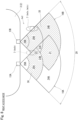
- the setting unit 34 sets the overlapping regions 21, 23B and the non-overlapping regions 24A, 25A, 26A as the start zone 35, and sets the overlapping regions 22, 23A and the non-overlapping region 25B as the trigger zone 36.
- the non-overlapping regions 24B and 26B are set neither as the start zone 35 nor as the trigger zone 36.
- the setting unit 34 sets the first detection range 16A (sections 17A to 19A) other than the overlapping regions 22, 23A overlapping with the second sections 18B of the second detection range 16B as the start zone 35, and sets the second section 18B of the second detection range 16B as the trigger zone 36.
- the setting unit 34 sets a part of the first detection range 16A as the start zone 35, and a part of the second detection range 16B as the trigger zone 36. Note that it is also possible to set the entire first detection range 16A as the start zone 35, and to set the second section 18B of the second detection range 16B other than the overlapping regions 22, 23A as the trigger zone 36.
- the third section 19A (non-overlapping region 26A) that is too close to the detector 13A and can cause an erroneous detection may be excluded from the start zone 35. Furthermore, it is also possible to change whether to include the non-overlapping region 26A in the start zone 35, depending on the paragraph Sm1a to Sm1c in the setting movement Sm1.
- the setting unit 34 sets the overlapping regions 21, 23A and the non-overlapping regions 24B, 25B, 26B as the start zone 35, and sets the overlapping regions 22, 23B and the non-overlapping region 25A as the trigger zone 36.
- the non-overlapping regions 24A and 26A are set neither as the start zone 35 nor as the trigger zone 36.
- the setting unit 34 sets the second detection range 16B (sections 17B to 19B) other than the overlapping regions 22, 23B overlapping with the second section 18A of the first detection range 16A as the start zone 35, and sets the second section 18A of the first detection range 16A as the trigger zone 36.
- the setting unit 34 sets a part of the second detection range 16B as the start zone 35, and a part of the first detection range 16A as the trigger zone 36. Note that it is also possible to set the entire second detection range 16B as the start zone 35, and to set the second section 18A of the first detection range 16A other than the overlapping regions 22, 23B as the trigger zone 36.
- the third section 19B (non-overlapping region 26B) that is too close to the detector 13B and can cause an erroneous detection may be excluded from the start zone 35. Furthermore, it is also possible to change whether to include the non-overlapping region 26B in the start zone 35, depending on the paragraph Sm2a to Sm2c in the setting movement Sm2.
- the setting unit 34 sets a part of one of the detection ranges 16A and 16B as the start zone 35, and sets a part of the other one of the detection ranges 16A and 16B as the trigger zone 36. Therefore, it is possible to ensure a large area for the start zone 35 in which the first phase Sm1a, Sm2a of the setting movement Sm1, Sm2 is to be detected. Hence, it is possible to ensure a distance to the trigger zone 36 in which the second phase Sm1b, Sm2b of the setting movements Sm1, Sm2 is to be detected.
- the area of the start zone 35 is small, only a short distance can be ensured to the trigger zone 36, and therefore, there is a chance that, by the time at which the setting unit 34 finishes the mode setting, the moving object has already moved into the trigger zone 36.
- this embodiment because a large area can be ensured for the start zone 35, it is possible to suppress such shortcomings.
- the setting unit 34 sets the overlapping regions 21, 23A, 23B as the start zone 35, and sets the overlapping region 22 as the trigger zone 36.
- the non-overlapping regions 24A, 24B to 26A, and 26B are set neither as the start zone 35 nor as the trigger zone 36.
- the setting unit 34 sets the regions 21, 23A, 23B other than the overlapping region 22 where the second sections 18A and 18B overlap each other, as the start zone 35, and sets the overlapping region 22 where the second sections 18A and 18B overlap each other as the trigger zone 36. Note that it is also possible not to set the overlapping regions 23A and 23B either as the start zone 35 or as the trigger zone 36.
- the setting unit 34 sets a part of the overlapping region where the first detection range 16A and the second detection range 16B overlap each other, the part being farther away from the door 2, as the start zone 35, and sets a part nearer to the door 2 than the start zone 35 as the trigger zone 36.
- the control unit 30 causes the detectors 13A, 13B to start detecting the detection target 7, and performs control for automatically opening or closing the door 2.
- the control unit 30 determines that the detection target 7 that is a moving object has made any one of the setting movements Sm1, Sm2, Sm3 on the basis of the changes in the measurement distances Md1, Md2 obtained from the detection results of the detectors 13A, 13B, that is, on the basis of changes in the position of the moving object determined by the determination unit 33
- the control unit 30 outputs a driving signal for causing the driving unit 28 to open or to close the door 2.
- the control unit 30 makes the determination as to whether the movement constitutes a setting movement Sm1, Sm2, Sm3, without using the measurement distances Md1, Md2 of the detection target 7 having been determined as an immovable object by the determination unit 33.
- the setting movement Sm1 for the left access mode is set to a series of movements in which the moving object moves from the start zone 35 (the regions 21, 23B, 24A, 25A, 26A) denoted as Sm1a to the trigger zone 36 (the regions 22, 23A, 25B) denoted as Sm1b, and returns to the start zone 35 (the regions 21, 23B, 24A, 25A, 26A) denoted as Sm1c. Note that, for the third phase Sm1c of returning to the start zone 35, it is possible for the non-overlapping region 26A not to be included in the start zone 35.
- the control unit 30 can determine that the detection target 7 is located inside of one of the non-overlapping regions 24A to 26A.
- the control unit 30 can determine that the detection target 7 is located inside of the overlapping region 21 or 23B. In these cases, the control unit 30 can determine that the detection target 7 is located inside the start zone 35 for the left access mode.
- the control unit 30 can determine that the detection target 7 is located inside the overlapping region 23A or 22.
- the control unit 30 can determine that the detection target 7 is located inside the non-overlapping region 25B. In these cases, the control unit 30 can determine that the detection target 7 is located inside the trigger zone 36 for the left access mode.
- the setting movement Sm2 for the right access mode is set to a series of movements in which the moving object moves from the start zone 35 (the regions 21, 23A, 24B, 25B, 26B) denoted as Sm2a to the trigger zone 36 (the regions 22, 23B, 25A) denoted as Sm2b, and returns to the start zone 35 (the regions 21, 23A, 24B, 25B, 26B) denoted as Sm2c. Note that, for the third phase Sm2c of returning to the start zone 35, it is possible for the non-overlapping region 26B not to be included in the start zone 35.
- the control unit 30 can determine that the detection target 7 is located inside any one of the non-overlapping regions 24B to 26B.
- the control unit 30 can determine that the detection target 7 is located inside the overlapping region 21 or 23A. In these cases, the control unit 30 can determine that the detection target 7 is located inside the start zone 35 for the right access mode.
- the control unit 30 can determine that the detection target 7 is located inside the overlapping region 22 or 23B.
- the control unit 30 can determine that the detection target 7 is located inside the non-overlapping region 25A. In these cases, the control unit 30 can determine that the detection target 7 is located inside the trigger zone 36 for the right access mode.
- the setting movement Sm3 for the center access mode is set to a series of movements in which the moving object moves from the start zone 35 (the regions 21, 23A, 23B) denoted as Sm3a to the trigger zone 36 (the region 22) denoted as Sm3b, and returns to the start zone 35 (the regions 21, 23A, 23B) denoted as Sm3c.
- the control unit 30 can determine that the detection target 7 is located inside the overlapping region 21.
- the control unit 30 can determine that the detection target 7 is located inside the overlapping region 23A.
- the control unit 30 can determine that the detection target 7 is located inside the overlapping region 23B. In these cases, the control unit 30 can determine that the detection target 7 is located inside the start zone 35 for the center access mode.
- the control unit 30 can determine that the detection target 7 is located inside the overlapping region 22. In this case, the control unit 30 can determine that the detection target 7 is located inside the trigger zone 36 for the center access mode.
- the control unit 30 causes the detectors 13A, 13B to detect the detection target 7 repeatedly at every set time interval (e.g., 80 msec) (step S2), causes the measurement unit 32 to collect the measurement distances Md1, Md2 (step S3), causes the determination unit 33 to determine whether the object is a moving object or an immovable object (step S4), causes the setting unit 34 to carry out the mode setting processing (step S5), and causes the driving unit 28 to open (step S8) or close (step S9) the door 2 when the moving object makes any one of the setting movements Sm1, Sm2, Sm3 (step S6). Note that, when the authentication by the authentication unit 29 does not succeed, the ECU 5 disables the driving of the driving unit 28.
- the ECU 5 disables the driving of the driving unit 28.
- step S1 the control unit 30 initializes (erases) the measurement distances Md1a, Md2a to Md1j, Md2j stored in the previous door open/close control in the storage unit 31.
- step S2 the first detector 13A is then caused to transmit and to receive an ultrasonic wave, and after waiting for a certain time period for allowing the reverberation to completely disappear, the second detector 13B is then caused to transmit and to receive an ultrasonic wave.
- the detectors 13A, 13B causes the transmitters 14 to transmit ultrasonic waves and causes the receivers 15 to receive the reflected waves alternately, to prevent erroneous cross-detections between the detectors 13A, 13B.
- step S3 the measurement unit 32 calculates each of the distances Md1, Md2 from each of the detectors 13A, 13B to the detection target 7, on the basis of the detection results (time from the transmission to the reception) of the detectors 13A, 13B. At this time, the measurement unit 32 receives the same number of detection results as the number of detection targets 7, and the measurement unit 32 calculates the distances Md1, Md2 with respect to the detection target 7 using the detection result having received earliest.
- step S4 using the current measurement distances Md1, Md2 and the previous measurement distances Md1a, Md2a stored in the storage unit 31, the determination unit 33 calculates the moving speeds Ms1, Ms2 of the detection target 7 from the respective amounts of change. Based on the calculated moving speeds Ms1, Ms2 and the determination value Jv, the determination unit 33 determines whether each of the first detection target 7 detected by the first detector 13A and the second detection target 7 detected by the second detector 13B is a moving object or an immovable object.
- step S5 the mode setting processing is performed, and the process is shifted to step S6.
- the mode setting processing will be described later in detail.
- step S6 the control unit 30 detects the movement of the moving object between the start zone 35 and the trigger zone 36, on the basis of the changes in the measurement distances Md1, Md2 obtained from the detection results of the respective detectors 13A, 13B, and determines whether the movement constitutes any one of the setting movements Sm1, Sm2, Sm3. If the movement constitutes any one of the setting movements Sm1, Sm2, and Sm3, the process is shifted to step S7. If the movement constitutes none of the setting movements Sm1, Sm2, and Sm3, the process is returned to step S2.
- the detection of the setting movement if an entry of the moving object from the start zone 35 to the trigger zone 36 is determined, the result of the determination of the entry to the trigger zone is stored in the storage unit 31. This stored result is erased when a setting movement is detected.
- step S7 the control unit 30 detects whether the door 2 is closed or open. If the door 2 is closed, a driving signal for opening the door 2 is output to the driving unit 28 in step S8, and the process is returned to step S2. If the door is open, a driving signal for closing the door 2 is output to the driving unit 28 in step S9, and the process is returned to step S2.
- the setting unit 34 determines whether to change the mode setting based on the determination result of the determination unit 33, and the result of determining how the setting movement Sm1, Sm2, Sm3 has progressed, by the control unit 30. Specifically, in step S5-1, in order to avoid unintended resetting of the mode after the mode setting, the setting unit 34 reads information pertaining to whether determination of an entry of the moving object into the trigger zone 36 has been established through the setting movement detection in step S6. If a movement constituting an entry has been detected, the process is returned without performing the subsequent steps. If a movement constituting an entry has not been detected, the process is shifted to step S5-2.
- the time required for the user as the moving object to move from the start zone 35 to the trigger zone 36 is usually about 300 msec, assuming that a human walks at a speed of 1300 mm/sec, for example.
- the determination unit 33 is configured to finalize the determination of whether an object is a moving object or an immovable object, upon obtaining the same result successively for a predetermined number of times (for example, eight times), it will take 640 msec for the determination unit 33 to make the determination.
- the time required for the user to move from the start zone 35 to the trigger zone 36 is shorter than the time required for the determination unit 33 to make the determination as to whether the object is a moving object or an immovable object. Therefore, in the normal operation, the setting unit 34 does not change the mode to another while the user is moving from the start zone 35 to the trigger zone 36 once the mode is set.
- step S5-2 it is determined whether the determinations of the determination unit 33 indicate that both of the first detection target 7 and the second detection target 7 are immovable objects. If both are immovable objects, the process is returned, without performing any subsequent steps. If at least one of the first detection target 7 or the second detection target 7 is determined not to be an immovable object, the process is shifted to step S5-3. Note that returning in steps S5-1 and S5-2 without performing step S5-3 and subsequent steps means maintaining the current mode setting.
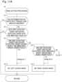
- step S5-3 it is determined whether the first detection target 7 is a moving object and the second detection target 7 is an immovable object. If this condition is met, the process is shifted to step S5-4, and the mode is set to the left access mode and the process is returned. If the condition is not met in step S5-3, by contrast, the process is shifted to step S5-5, and it is determined whether the first detection target 7 is an immovable object and the second detection target 7 is a moving object. If this condition is met, the process is shifted to step S5-6, and the mode is set to the right access mode, and the process is returned. If the condition is not met in step S5-5, by contrast, that is, if both of the detection targets 7 are moving objects, the process is shifted to step S5-7.
- step S5-7 the setting unit 34 determines whether the difference (Md1-Md2) between the measurement distances Md1, Md2 obtained by the measurement unit 32 is less than the lower bound Sr1 of the setting range Sr. If the condition is met, that is, if the detection target 7 is located on the side nearer to the first detector 13A, the process is shifted to step S5-4 shown in Fig. 11A . The mode is then set to the left access mode and the process is returned. If the condition is not met in step S5-7, the process is shifted to step S5-8.
- step S5-8 the setting unit 34 determines whether the difference (Md1-Md2) between the measurement distances Md1, Md2 measured by the measurement unit 32 is greater than the upper bound Sr2 of the setting range Sr. If the condition is met, that is, if it is indicated that the detection target 7 is located on the side nearer to the second detector 13B, the process is shifted to step S5-6 shown in Fig. 11A . The mode is then set to the right access mode, and the process is returned. If the condition is not met in step S5-8, the process is shifted to step S5-9.
- step S5-9 the setting unit 34 carries out mode setting to the center access mode, and goes back to the previous step. Specifically, if the difference (Md1-Md2) between the measurement distances Md1, Md2 obtained by the measurement unit 32 is within the setting range Sr (Sr1 ⁇ Md1-Md2 ⁇ Sr2), that is, if the difference indicates that the detection target 7 is located near the center of the back surface of the vehicle body 3, the mode is set to the center access mode.
- the setting unit 34 carries out the mode setting to any one of the left access mode, the right access mode, and the center access mode, on the basis of the position where the moving object has made an entry. Therefore, the user who is the moving object can perform the setting movements Sm1, Sm2, Sm3 from that point in time. In this manner, user operability of the door opening and closing apparatus 10 can be improved.
- the door opening and closing apparatus 10 configured as described above has the following characteristics.
- the setting unit 34 sets at least a part of one of the first detection range 16A and the second detection range 16B as a start zone (first zone) 35 in which a first phase Sm1a, Sm2a of a setting movement Sm1, Sm2 is to be detected, on the basis of the distances Md1, Md2 measured by the measurement unit 32.
- the setting unit 34 also sets a part of another one of the first detection range 16A and the second detection range 16B as a trigger zone (second zone) 36 in which a second phase Sm1b, Sm2b of the setting movement Sm1, Sm2 is to be detected.
- the left access mode because a part of the first detection range 16A is set as the start zone 35 and a part of the second detection range 16B is set as the trigger zone 36, it is possible to improve the operability when the user makes an entry from the left side along the door 2 and makes the setting movement Sm1.
- the right access mode because a part of the second detection range 16B is set as the start zone 35 and a part of the first detection range 16A is set as the trigger zone 36, it is possible to improve the operability when the user makes an entry from the right side along the door 2 and makes the setting movement Sm2.
- the setting unit 34 When the difference between the distances Md1, Md2 measured by the measurement unit 32 is outside the setting range Sr, and the second distance Md2 is greater than the first distance Md1, the setting unit 34 carries out mode setting to the left access mode. When the difference between the distances Md1, Md2 measured by the measurement unit 32 is outside the setting range Sr, and the second distance Md2 is shorter than the first distance Md1, the setting unit 34 carries out mode setting to the right access mode. In other words, the position of the detection target 7 with respect to the door 2 is determined on the basis of the difference between the distances Md1, Md2 measured by the measurement unit 32 and the setting range Sr, and an appropriate mode is set accordingly. Therefore, the operability of the user opening and closing the door 2 can be improved.
- the setting unit 34 sets the first section 17A of the first detection range 16A and the second section 18A of the first detection range 16A excluding a region overlapping with the second section 18B of the second detection range 16B, as the start zone 35.
- the setting unit 34 sets the first section 17B of the second detection range 16B and the second section 18B of the second detection range 16B excluding a region overlapping with the second section 18A of the first detection range 16A as the start zone 35. Therefore, it is possible to ensure a large area for the start zone 35 in which the first phase Sa, Sm2a of the setting movement Sm1, Sm2 is to be detected.
- the start zone 35 is small, by the time the first detector 13A or the second detector 13B detects a user and the setting unit 34 sets the mode, the user might have already moved to the trigger zone 36. Because the start zone 35 has a large area, such inconvenience is less likely to occur.
- the setting unit 34 sets the region where the first detection range 16A and the second detection range 16B overlap each other excluding a region where the second sections 18A, 18B of the first detection range 16A and the second detection range 16B overlaps each other, as the start zone 35. Therefore, it is possible to improve the operability of the time when the user makes the setting movement Sm3 of moving toward the door 2.
- the setting unit 34 sets the center access mode when the difference between the distances Md1, Md2 measured by the measurement unit 32 is within the setting range Sr.
- the position of the detection target 7 with respect to the door 2 is determined on the basis of the difference between the distances Md1, Md2 measured by the measurement unit 32 and the setting range Sr, and an appropriate mode is set accordingly. Therefore, the operability of the user opening and closing the door 2 can be improved.
- the setting unit 34 When the determination unit 33 determines that the first detection target 7 detected by the first detector 13A is a moving object and the second detection target 7 detected by the second detector 13B is an immovable object, the setting unit 34 carries out mode setting to the left access mode. When the determination unit 33 determines that the first detection target 7 detected by the first detector 13A is an immovable object and the second detection target 7 detected by the second detector 13B is a moving object, the setting unit 34 sets the right access mode. When the determination unit 33 determines that both the first detection target 7 and the second detection target 7 are moving objects, the setting unit 34 performs mode setting on the basis of the difference between the distances Md1, Md2 measured by the measurement unit 32 and the setting range Sr. Therefore, the direction in which the user makes the entry can be determined accurately, and the mode settings can be carried out appropriately.
- the mode setting by the setting unit 34 may not include the center access mode.
- specific setting regions can be changed as necessary as long as the start zone 35 is set to a part of one of the first detection range 16A and the second detection range 16B, and the trigger zone 36 is set to a part of the other.
- a display device enabled to display the ground in the trigger zone 36 may be provided so as to guide the user by displaying the ground, when the setting movement Sm1, Sm2, Sm3 is to be detected.
- a guidance is not limited to visual guidance, and means for guiding the user auditorily, such as a buzzer, may also be provided.
Landscapes
- Power-Operated Mechanisms For Wings (AREA)
Abstract
Description
- The present invention relates to a door opening and closing apparatus and a door opening and closing method.
- A door opening and closing apparatus capable of automatically opening and closing a door without a user touching the handle of the door is known. Such a door opening and closing apparatus includes a pair of detectors each including an ultrasonic sensor, and detects a user who is within a fan-shaped detection range, using ultrasonic waves emitted from the detectors. When it is determined that the user has made a predetermined setting movement, on the basis of changes in the distance of the user, the change being obtained from detection results of the pair of detectors, a driving unit is caused to open or to close the door.
-
Patent Document 1 discloses a door opening and closing apparatus configured to determine an entry position of a user on the basis of detection results of a pair of detectors, to set a mode to one of a side access mode or a center access mode, and to open or to close the door upon detecting a setting movement. In the side access mode, a user's movement in a direction in parallel with the door is detected as the setting movement, on the basis of a detection result of one of the pair of detectors. In the center access mode, a user's movement in a direction intersecting with the door is detected as the setting movement, on the basis of the detection result of each of the pair of detectors. - Patent Document 1:
JP-A-2020-180523 - Because a detector has a fan-shaped detection range gradually spreading away from the detector, the range where a user is detectable near the door is small. Therefore, in the side access mode, it is difficult ensure the area (distance) for allowing user to make the setting movement. In this regard, the door opening and closing apparatus according to
Patent Document 1 has room for improvement in operability. - An object of the present invention is to provide a door opening and closing apparatus and a door opening and closing method capable of ensuring an area for allowing a user to make a setting movement along a door, and improving operability in opening and closing the door.
- According to the present invention, there provided is a door opening and closing apparatus including: a driving unit configured to open and to close a door with respect to a vehicle body; a first detector configured to repeatedly detect a detection target that is present within a first detection range set around the door; a second detector disposed spaced apart from the first detector in a horizontal direction and configured to repeatedly detect the detection target that is present within a second detection range set around the door in a manner partially overlapping with the first detection range; a measurement unit configured to measure a first distance from the first detector to the detection target based on a detection result of the first detector, and to measure a second distance from the second detector to the detection target based on a detection result of the second detector; a setting unit configured to set at least a part of one of the first detection range and the second detection range as a first zone in which a first phase of a setting movement of the detection target is to be detected, and to set a part of another one of the first detection range and the second detection range as a second zone in which a second phase of the setting movement is to be detected, based on the first distance and the second distance measured by the measurement unit; and a control unit configured to cause the driving unit to open or to close the door upon determining that the detection target has performed the setting movement including a movement between the first zone and the second zone, based on a change in the first distance and a change in the second distance measured by the measurement unit.
- The door opening and closing apparatus includes the setting unit configured to set at least a part of one of the first detection range and the second detection range as the first zone in which the first phase of the setting movement is to be detected, and to set a part of another one of the first detection range and the second detection range as the second zone in which the second phase of the setting movement is to be detected, based on the first distance and the second distance measured by the measurement unit. Therefore, as compared with a configuration in which the first zone and the second zone are set within the detection range of one of the first detector and the second detector, it is possible to ensure an area for allowing a user to make the setting movement. Hence, the operability for the user in opening and closing the door can be improved.
- With the door opening and closing apparatus according to the present invention, it is possible to ensure an area for allowing a user to make a setting movement along a door, and to improve the operability in opening and closing the door.
-
-
Fig. 1 is a block diagram of a door opening and closing apparatus according to an embodiment of the present invention. -
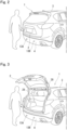
Fig. 2 is a perspective view showing the door having been closed. -
Fig. 3 is a perspective view showing the door having been opened. -
Fig. 4 is a plan view providing a summary of mode settings with respect to a first detection range and a second detection range. -
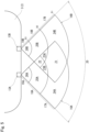
Fig. 5 is a plan view showing the first detection range and the second detection range. -
Fig. 6 is a table showing mode settings that are based on a detection target detected by a first detector and a second detector, and the positions of the detection target with respect to the door. -
Fig. 7 is a plan view showing a start zone and a trigger zone in a left access mode. -
Fig. 8 is a plan view showing a start zone and a trigger zone in a right access mode. -
Fig. 9 is a plan view showing a start zone and a trigger zone in a center access mode. -
Fig. 10 is a flowchart showing main control of a control unit. -
Fig. 11A is a flowchart showing mode setting processing inFig. 10 . -
Fig. 11B is a flowchart subsequent to the flowchart inFig. 11A . - An embodiment of the present invention will now be explained with reference to drawings.
- Referring to
Figs. 1 to 3 , a door opening and closingapparatus 10 for a vehicle according to an embodiment of the present invention is configured to automatically open or close adoor 2 without the user using his/her hand, in response to a user making one of predetermined setting movements Sm1, Sm2, Sm3 (seeFigs. 7 ,8 , and9 , respectively) in front of thedoor 2 of thevehicle 1. In the present embodiment, thedoor 2 to be controlled is a hatchback door. However, thedoor 2 to be controlled may be any door other than a hatchback door. - Referring to
Fig. 1 , the door opening and closingapparatus 10 includes adetection unit 12, adriving unit 28, anauthentication unit 29, and acontrol unit 30. InFig. 1 , the part surrounded by a one-dot chain line represents newly added configurations, and, for theauthentication unit 29, an existing component mounted on thevehicle 1 is used. If thevehicle 1 is equipped with back sonar sensors for monitoring the rear side of thevehicle 1 during driving, the existing components may be used as thedetection unit 12. If thevehicle 1 is equipped with a remote-controlled automatic door enabled to automatically open and close thedoor 2, with the use of a key (portable device), the existing components may be used as thedriving unit 28. - The
detection unit 12 includes twodetectors detection targets 7 according to the present invention. - Referring to
Fig. 1 , thecontrol unit 30 includes astorage unit 31, ameasurement unit 32 configured to measure the distance from each of thedetectors detection target 7, adetermination unit 33 configured to determine whether thedetection target 7 is a moving object or an immovable object, and asetting unit 34 configured to carry out mode setting. Referring toFig. 4 , thesetting unit 34 carries out mode setting to any one of a left access mode (first access mode), a right access mode (second access mode), and a center access mode (third access mode) on the basis of the position of thedetection target 7 detected earliest, with respect to thedoor 2. Each of these modes uses a start zone (first zone) 35 and a trigger zone (second zone) 36 that are allocated differently among the modes. Thecontrol unit 30 detects a movement of an object having been determined as a moving object by thedetermination unit 33, on the basis of a change in distances Md1, Md2 measured by themeasurement unit 32. If it is determined that the movement of the moving object constitutes any one of setting movements Sm1, Sm2, Sm3 (seeFigs. 7 ,8 , and9 , respectively) specified by thesetting unit 34, the setting movements each including a movement between thestart zone 35 and thetrigger zone 36, thedriving unit 28 is caused to open or to close thedoor 2. - Referring to
Figs. 7 to 9 , a series (a plurality of phases) of forward and rearward movements is established as each of the setting movements Sm1, Sm2, Sm3, and different series of movements are set for the left access mode, the right access mode, and the center access mode, respectively. Referring toFig. 7 , the first setting movement Sm1 is for the left access mode used when thedetection target 7 approaches thedoor 2 from the left side of thevehicle body 3, and is specified as a series of movements of thedetection target 7 moving ahead toward the right side along thedoor 2, and then moving back to the left side (Sm1a→Sm1b→Sm1c). Referring toFig. 8 , the second setting movement Sm2 is for the right access mode in which the user approaches thedoor 2 from the right side of thevehicle body 3, and is specified as a series of user movements of moving ahead toward the left side along thedoor 2 and then moving back to the right side (Sm2a→Sm2b→Sm2c). Referring toFig. 9 , the third setting movement Sm3 is for the center access mode in which the user approaches thedoor 2 from the rear side of thevehicle body 3, and is specified as a series of user movements of moving ahead toward thedoor 2 and then moving back away from the door 2 (Sm3a→Sm3b→Sm3c). Note that these setting movements Sm1, Sm2, Sm3 may be any movements other than a series of forward and rearward movements. - The
detection unit 12, thedriving unit 28, theauthentication unit 29, and thecontrol unit 30 will now be described specifically. - Referring to
Figs. 1 to 4 , thedetection unit 12 includes twodetectors rear bumper 4 of thevehicle body 3 in a manner interspaced from each other in the vehicle width direction (horizontal direction) along thedoor 2. Thedetectors detection target 7 within respective predetermineddetection ranges door 2 will be sometimes referred to as afirst detector 13A, and the detector on the right side in a view from the direction directly facing thedoor 2 will be sometimes referred to as asecond detector 13B. - Referring to
Fig. 1 , each of thedetectors transmitter 14 and areceiver 15, and is communicably connected to thecontrol unit 30 by a communication cable. - Referring to
Fig. 5 , the ultrasonic waves emitted from thetransmitters 14 of thedetectors door 2 in a substantially conical shape. On the ground, each of the detection ranges 16A, 16B spreads in a fan-like shape (e.g., with a center angle of about 90 degrees). The detection central axis (not shown) of each of the detection ranges 16A, 16B extends rearwards, in parallel with the vehicle length direction. The detection ranges 16A, 16B partially overlap each other. In the description hereunder, the detection range of thefirst detector 13A will be sometimes referred to as afirst detection range 16A, and the detection range of thesecond detector 13B will be sometimes referred to as asecond detection range 16B. - The
receiver 15 receives waves that are reflections of the ultrasonic waves transmitted from thetransmitter 14. Thereceiver 15 outputs the detection result to thecontrol unit 30. This detection result is used in calculating the distance to thedetection target 7, in calculating the speed of the movement of thedetection target 7, and also in determining the presence of adetection target 7 in the detection ranges 16A, 16B. It is also possible for thedetectors Fig. 1 ) of thevehicle 1, and for theECU 5 to input the detection results from thedetectors control unit 30. - The detection ranges 16A, 16B corresponding to the
respective detectors Fig. 5 . - The detection ranges 16A, 16B are set as regions within a specified distance D1 (e.g., 900 mm) from the
respective detectors first detection range 16A and thesecond detection range 16B combined together form anapproach region 20 for starting the detection of the setting movements Sm1, Sm2, Sm3 when a moving object moves thereinto. - Each of the detection ranges 16A, 16B is divided into a
first section second section third section detector unit 34 for the purpose of identifying the position of thedetection target 7 within theapproach region 20. The specified distance D2 is shorter than the specified distance D1 (e.g., 500 mm), and the specified distance D3 is shorter than the specified distance D2 (e.g., 200 mm). The section between the specified distances D1 and D2 corresponds to the first section (first portion detector first sections second sections third sections third sections - The
approach region 20 formed by the detection ranges 16A, 16B thus divided includes three types of overlappingregions non-overlapping regions detection target 7 in the overlappingregion first detector 13A and thesecond detector 13B. Thedetection target 7 in thenon-overlapping regions second detector 13B. Thedetection target 7 in thenon-overlapping region second detector 13B but not by thefirst detector 13A. - The first
overlapping region 21 is a region where thefirst section 17A of thefirst detection range 16A and thefirst section 17B of thesecond detection range 16B overlap each other. - The second
overlapping region 22 is a region where thesecond section 18A of thefirst detection range 16A and thesecond section 18B of thesecond detection range 16B overlap each other. The secondoverlapping region 22 is adjacent to the first overlappingregion 21 on the side nearer to thevehicle body 3. - The third
overlapping region 23A is a region where thefirst section 17A of thefirst detection range 16A and thesecond section 18B of thesecond detection range 16B overlap each other. The thirdoverlapping region 23B is a region where thesecond section 18A of thefirst detection range 16A and thefirst section 17B of thesecond detection range 16B overlap each other. InFig. 5 , the thirdoverlapping region 23A is adjacent to the overlappingregions regions overlapping region 23B is adjacent to the overlappingregions regions - The first
non-overlapping region 24A is a region corresponding to thefirst section 17A of thefirst detection range 16A excluding the part overlapping with thesecond detection range 16B. The firstnon-overlapping region 24B is a region corresponding to thefirst section 17B of thesecond detection range 16B excluding the part overlapping with thefirst detection range 16A. InFig. 5 , the firstnon-overlapping region 24A is adjacent to the first overlappingregion 21 on the left side of the first overlappingregion 21, and the firstnon-overlapping region 24B is adjacent to the first overlappingregion 21 on the right side of the first overlappingregion 21. - The second
non-overlapping region 25A is a region corresponding to thesecond section 18A of thefirst detection range 16A excluding the part overlapping with thesecond detection range 16B. The secondnon-overlapping region 25B is a region corresponding to thesecond section 18B of thesecond detection range 16B excluding the part overlapping with thefirst detection range 16A. InFig. 5 , the secondnon-overlapping region 25A is adjacent to the firstnon-overlapping region 24A on the side nearer to thevehicle body 3, and adjacent to the overlappingregions regions non-overlapping region 25B is adjacent to the firstnon-overlapping region 24B on the side nearer to thevehicle body 3, and adjacent to the overlappingregions regions - The third
non-overlapping region 26A corresponds to thethird section 19A of thefirst detection range 16A. The thirdnon-overlapping region 26B corresponds to thethird section 19B of thesecond detection range 16B. InFig. 5 , the thirdnon-overlapping region 26A is adjacent to the secondnon-overlapping region 25A on the side nearer to thevehicle body 3, and the thirdnon-overlapping region 26B is adjacent to the secondnon-overlapping region 25B on the side nearer to thevehicle body 3. - Referring to
Figs. 1 to 3 , the drivingunit 28 is disposed between thevehicle body 3 and thedoor 2, and is configured to open or to close thedoor 2 by being driven by thecontrol unit 30 that is electrically connected thereto. Although the configuration of the drivingunit 28 is not specifically shown, the drivingunit 28 includes a motor, a gear mechanism, and a damper by which thedoor 2 can be rotated in the directions to open and to close. Note that the drivingunit 28 may also be electrically connected to theECU 5, and thecontrol unit 30 may drive the drivingunit 28 via theECU 5. - The
authentication unit 29 includes a transceiver having an external lowfrequency (LF) transmission/reception antenna via which theauthentication unit 29 communicates with a key using an LF signal, and is configured to authenticate a key outside the vehicle and to determine whether the moving object is the user (authentication processing). The transceiver is communicably connected to theECU 5 by a communication cable, and is activated in response to a command issued by theECU 5 and performs communication related to the authentication processing. In the authentication processing, theauthentication unit 29 requests transmission of an authentication code from the key, and compares the authentication code received from the key with a registered authorized code. When the authentication code matches the authorized code (authentication succeeds), theECU 5 electrically connected to theauthentication unit 29 determines that the moving object is the user, and permits the drivingunit 28 to open and to close thedoor 2. When the authentication code does not match the authorized code (authentication fails), theECU 5 electrically connected to theauthentication unit 29 determines that the moving object is a third party, and disables the opening and closing operation of thedoor 2 by the drivingunit 28. To disable herein means not to drive the drivingunit 28, for example, by interrupting a driving signal output from thecontrol unit 30 so that the driving signal is not input to the drivingunit 28. - Referring to
Fig. 1 , thecontrol unit 30 is communicably connected to thedetection unit 12, and is electrically connected to the drivingunit 28. Thecontrol unit 30 is communicably or electrically connected to theECU 5. Thecontrol unit 30 includes thestorage unit 31, themeasurement unit 32, thedetermination unit 33, and thesetting unit 34, and is implemented by one or more microcomputers and other electronic devices. Note that each of thestorage unit 31, themeasurement unit 32, thedetermination unit 33, and thesetting unit 34 may be implemented as a microcomputer and other electronic devices that are different from those of thecontrol unit 30. - The
storage unit 31 stores therein a control program, setting data such as a threshold and a determination value used in the control program, and a data table for calculating a distance from detection results of thedetectors storage unit 31 also stores therein the measurement distances Md1, Md2 measured by themeasurement unit 32. In the present embodiment, thestorage unit 31 is capable of storing ten measurement distances Md1a, Md2a to Md1j, Md2j. When the latest measurement distances Md1, Md2 are to be stored additionally to the ten measurements in thestorage unit 31, the oldest measurement distances Md1j, Md2j are erased. - The
measurement unit 32 measures the first distance Md1 between thefirst detector 13A and thedetection target 7 on the basis of the time (detection result) from when thetransmitter 14 in thefirst detector 13A has transmitted an ultrasonic wave to when thereceiver 15 in thefirst detector 13A receives the reflected wave. The second distance Md2 between thesecond detector 13B and thedetection target 7 is measured on the basis of the time from when thetransmitter 14 in thesecond detector 13B has transmitted an ultrasonic wave to when thereceiver 15 in thesecond detector 13B receives the reflected wave. In other words, themeasurement unit 32 and thedetectors detectors detection target 7. When there are two ormore detection targets 7 at different positions in the detection ranges 16A, 16B, the same number of measurements are collected by thedetectors measurement unit 32 calculates the distances Md1, Md2 with respect to thedetection target 7 on the basis of the detection result having been received earliest. In other words, afirst detection target 7 detected by thefirst detector 13A and asecond detection target 7 detected by thesecond detector 13B may be the same object or different objects. The measurement distances Md1, Md2 are stored in thestorage unit 31. - The
determination unit 33 determines whether thedetection target 7 detected by each of thedetectors determination unit 33 calculates the speed Ms1 at which the detection target (first detection target) 7 detected by thefirst detector 13A moves, on the basis of the latest first measurement distance Md1 and the previous first measurement distance Md1a stored in thestorage unit 31. The moving speed Ms1 is then compared with a predetermined determination value (set speed) Jv (e.g., 20 mm/s). If the moving speed Ms1 is higher than or equal to the determination value Jv, it is determined that thedetection target 7 is a moving object. If the moving speed Ms1 is lower than the determination value Jv, it is determined that thedetection target 7 is an immovable object. Thedetermination unit 33 also calculates the speed Ms2 at which the detection target (second detection target) 7 detected by thesecond detector 13B moves, on the basis of the latest second measurement distance Md2 and the previous second measurement distance Md2a stored in thestorage unit 31. The moving speed Ms2 is then compared with the predetermined determination value Jv. If the moving speed Ms2 is higher than or equal to the determination value Jv, it is determined that thedetection target 7 is a moving object. If the moving speed Ms2 is lower than the determination value Jv, it is determined that thedetection target 7 is an immovable object. - If the differences (amounts of change) between the current measurement distances Md1, Md2 and the respective last measurement distances Md1a, Md2a are large, the
detection targets 7 have moved a long distance at high moving speeds Ms1, Ms2. If the amount of the change is small, thedetection targets 7 have moved a short distance, at low moving speeds Ms1, Ms2. Therefore, thedetermination unit 33 can determine whether thedetection target 7 detected by thefirst detector 13A is a moving object or an immovable object using a change in the first measurement distances Md1, and can determine whether thedetection target 7 detected by thesecond detector 13B is a moving object or an immovable object using the change in the second measurement distances Md2. Although thedetermination unit 33 may determine whether the object is a moving object or an immovable object only by performing the comparison once, it is preferable for thedetermination unit 33 to make a final determination when the same comparison result is obtained successively for a predetermined number of times (e.g., eight times = 640 msec). Note that it is also possible to use the gradient of the average of the detection results (the rate of change in the distance) across a predetermined number of times, as the moving speed Ms1, Ms2. - Referring to
Fig. 4 , the settingunit 34 carries out the mode setting to any one of the left access mode, the right access mode, and the center access mode on the basis of the detected position of thedetection target 7 with respect to thedoor 2. Each of these modes is specified with astart zone 35 in which a first phase Sm1a, Sm2a, Sm3a of corresponding one of the setting movements Sm1, Sm2, and Sm3 shown inFigs. 7 ,8 , and9 is to be detected, and atrigger zone 36 in which a second phase Sm1b, Sm2b, Sm3b of the setting movement Sm1, Sm2, Sm3 is to be detected. Thestart zone 35 and thetrigger zone 36 are allocated differently among the access modes. - Specifically, as shown in
Fig. 6 , when thedetermination unit 33 determines that thedetection target 7 detected by thefirst detector 13A is a moving object and thedetection target 7 detected by thesecond detector 13B is an immovable object, the settingunit 34 sets the left access mode shown inFig. 7 . When thedetermination unit 33 determines that thedetection target 7 detected by thefirst detector 13A is an immovable object and thedetection target 7 detected by thesecond detector 13B is a moving object, the settingunit 34 sets the right access mode shown inFig. 8 . - When the
determination unit 33 determines that both of thedetection target 7 detected by thefirst detector 13A and thedetection target 7 detected by thesecond detector 13B are moving objects, the settingunit 34 sets the mode on the basis of a difference (Md1-Md2) between the first measurement distance Md1 and the second measurement distance Md2, measured by themeasurement unit 32, and a preset setting range Sr. For example, a lower bound Sr1 of the setting range Sr is -100 mm, and an upper bound Sr2 of the setting range Sr is +100 mm. In other words, on the basis of whether the difference between the measurement distances Md1, Md2 is greater than or equal to the lower bound Sr1 and smaller than or equal to the upper bound Sr2, the settingunit 34 carries out mode setting to any one of the left access mode, the right access mode, and the center access mode. - When the difference (Md1-Md2) between the measurement distances Md1, Md2 falls outside of the setting range Sr, and the second measurement distance Md2 is greater than the first measurement distance Md1, that is, when the
detection target 7 is on the side nearer to thefirst detector 13A, the settingunit 34 carries out mode setting to the left access mode. When the difference (Md1-Md2) between the measurement distances Md1, Md2 falls outside the setting range Sr, and the second measurement distance Md2 is shorter than the first measurement distance Md1, that is, when thedetection target 7 is on the side nearer to thesecond detector 13B, the settingunit 34 carries out mode setting to the right access mode. When the difference (Md1-Md2) between the measurement distances Md1, Md2 falls within the setting range Sr, that is, when thedetection target 7 is near the center of thedoor 2, the settingunit 34 carries out mode setting to the center access mode. - By contrast, when the
determination unit 33 determines that both thedetection target 7 detected by thefirst detector 13A and thedetection target 7 detected by thesecond detector 13B are immovable objects, the settingunit 34 maintains the current mode setting having been set previously, without changing the mode to any one of the left access mode, the right access mode, and the center access mode. - Referring to
Figs. 5 and7 , in the left access mode, the settingunit 34 sets the overlappingregions non-overlapping regions start zone 35, and sets the overlappingregions non-overlapping region 25B as thetrigger zone 36. Thenon-overlapping regions start zone 35 nor as thetrigger zone 36. - That is, in the left access mode, the setting
unit 34 sets thefirst detection range 16A (sections 17A to 19A) other than the overlappingregions second sections 18B of thesecond detection range 16B as thestart zone 35, and sets thesecond section 18B of thesecond detection range 16B as thetrigger zone 36. In other words, in the left access mode, the settingunit 34 sets a part of thefirst detection range 16A as thestart zone 35, and a part of thesecond detection range 16B as thetrigger zone 36. Note that it is also possible to set the entirefirst detection range 16A as thestart zone 35, and to set thesecond section 18B of thesecond detection range 16B other than the overlappingregions trigger zone 36. Thethird section 19A (non-overlapping region 26A) that is too close to thedetector 13A and can cause an erroneous detection may be excluded from thestart zone 35. Furthermore, it is also possible to change whether to include thenon-overlapping region 26A in thestart zone 35, depending on the paragraph Sm1a to Sm1c in the setting movement Sm1. - Referring to
Figs. 5 and8 , in the right access mode, the settingunit 34 sets the overlappingregions non-overlapping regions start zone 35, and sets the overlappingregions non-overlapping region 25A as thetrigger zone 36. Thenon-overlapping regions start zone 35 nor as thetrigger zone 36. - That is, in the right access mode, the setting
unit 34 sets thesecond detection range 16B (sections 17B to 19B) other than the overlappingregions second section 18A of thefirst detection range 16A as thestart zone 35, and sets thesecond section 18A of thefirst detection range 16A as thetrigger zone 36. In other words, in the right access mode, the settingunit 34 sets a part of thesecond detection range 16B as thestart zone 35, and a part of thefirst detection range 16A as thetrigger zone 36. Note that it is also possible to set the entiresecond detection range 16B as thestart zone 35, and to set thesecond section 18A of thefirst detection range 16A other than the overlappingregions trigger zone 36. Thethird section 19B (non-overlapping region 26B) that is too close to thedetector 13B and can cause an erroneous detection may be excluded from thestart zone 35. Furthermore, it is also possible to change whether to include thenon-overlapping region 26B in thestart zone 35, depending on the paragraph Sm2a to Sm2c in the setting movement Sm2. - As described above, when a moving object makes an entry along the
door 2 from one side of thevehicle body 3, the settingunit 34 sets a part of one of the detection ranges 16A and 16B as thestart zone 35, and sets a part of the other one of the detection ranges 16A and 16B as thetrigger zone 36. Therefore, it is possible to ensure a large area for thestart zone 35 in which the first phase Sm1a, Sm2a of the setting movement Sm1, Sm2 is to be detected. Hence, it is possible to ensure a distance to thetrigger zone 36 in which the second phase Sm1b, Sm2b of the setting movements Sm1, Sm2 is to be detected. If the area of thestart zone 35 is small, only a short distance can be ensured to thetrigger zone 36, and therefore, there is a chance that, by the time at which thesetting unit 34 finishes the mode setting, the moving object has already moved into thetrigger zone 36. By contrast, in this embodiment, because a large area can be ensured for thestart zone 35, it is possible to suppress such shortcomings. - Referring to
Figs. 5 and9 , in the center access mode, the settingunit 34 sets the overlappingregions start zone 35, and sets the overlappingregion 22 as thetrigger zone 36. Thenon-overlapping regions start zone 35 nor as thetrigger zone 36. - That is, in the center access mode, among the regions where the
first detection range 16A and thesecond detection range 16B overlap each other, the settingunit 34 sets theregions region 22 where thesecond sections start zone 35, and sets the overlappingregion 22 where thesecond sections trigger zone 36. Note that it is also possible not to set the overlappingregions start zone 35 or as thetrigger zone 36. As described above, in the center access mode, the settingunit 34 sets a part of the overlapping region where thefirst detection range 16A and thesecond detection range 16B overlap each other, the part being farther away from thedoor 2, as thestart zone 35, and sets a part nearer to thedoor 2 than thestart zone 35 as thetrigger zone 36. - When the
vehicle 1 is parked and the engine is stopped, thecontrol unit 30 causes thedetectors detection target 7, and performs control for automatically opening or closing thedoor 2. When thecontrol unit 30 determines that thedetection target 7 that is a moving object has made any one of the setting movements Sm1, Sm2, Sm3 on the basis of the changes in the measurement distances Md1, Md2 obtained from the detection results of thedetectors determination unit 33, thecontrol unit 30 outputs a driving signal for causing the drivingunit 28 to open or to close thedoor 2. Thecontrol unit 30 makes the determination as to whether the movement constitutes a setting movement Sm1, Sm2, Sm3, without using the measurement distances Md1, Md2 of thedetection target 7 having been determined as an immovable object by thedetermination unit 33. - Referring to
Fig. 7 , the setting movement Sm1 for the left access mode is set to a series of movements in which the moving object moves from the start zone 35 (theregions regions regions start zone 35, it is possible for thenon-overlapping region 26A not to be included in thestart zone 35. - Referring to
Figs. 5 and7 , when the first measurement distance Md1 indicates that thefirst detection target 7 is located inside of any one of thefirst section 17A to thethird section 19A, and the second measurement distance Md2 indicates that nosecond detection target 7 is detected, thecontrol unit 30 can determine that thedetection target 7 is located inside of one of thenon-overlapping regions 24A to 26A. When the first measurement distance Md1 indicates that thefirst detection target 7 is located inside thefirst section 17A or thesecond section 18A, and the second measurement distance Md2 indicates that thesecond detection target 7 is located inside thefirst section 17B, thecontrol unit 30 can determine that thedetection target 7 is located inside of the overlappingregion control unit 30 can determine that thedetection target 7 is located inside thestart zone 35 for the left access mode. - When the first measurement distance Md1 indicates that the
first detection target 7 is located inside thefirst section 17A or thesecond section 18A, and the second measurement distance Md2 indicates that thesecond detection target 7 is located inside thesecond section 18B, thecontrol unit 30 can determine that thedetection target 7 is located inside the overlappingregion first detection target 7 is detected, and the second measurement distance Md2 indicates that thesecond detection target 7 is located inside thesecond section 18B, thecontrol unit 30 can determine that thedetection target 7 is located inside thenon-overlapping region 25B. In these cases, thecontrol unit 30 can determine that thedetection target 7 is located inside thetrigger zone 36 for the left access mode. - Referring to
Fig. 8 , the setting movement Sm2 for the right access mode is set to a series of movements in which the moving object moves from the start zone 35 (theregions regions regions start zone 35, it is possible for thenon-overlapping region 26B not to be included in thestart zone 35. - Referring to
Figs. 5 and8 , when the first measurement distance Md1 indicates that nofirst detection target 7 is detected, and the second measurement distance Md2 indicates that thesecond detection target 7 is located inside any one of thefirst section 17B to thethird section 19B, thecontrol unit 30 can determine that thedetection target 7 is located inside any one of thenon-overlapping regions 24B to 26B. When the first measurement distance Md1 indicates that thefirst detection target 7 is located inside thefirst section 17A, and the second measurement distance Md2 indicates that thesecond detection target 7 is located inside thefirst section 17B or thesecond section 18B, thecontrol unit 30 can determine that thedetection target 7 is located inside the overlappingregion control unit 30 can determine that thedetection target 7 is located inside thestart zone 35 for the right access mode. - When the first measurement distance Md1 indicates that the
first detection target 7 is located inside thesecond section 18A and the second measurement distance Md2 indicates that thesecond detection target 7 is located inside thefirst section 17B or thesecond section 18B, thecontrol unit 30 can determine that thedetection target 7 is located inside the overlappingregion first detection target 7 is located inside thesecond section 18A and the second measurement distance Md2 indicates that nosecond detection target 7 is detected, thecontrol unit 30 can determine that thedetection target 7 is located inside thenon-overlapping region 25A. In these cases, thecontrol unit 30 can determine that thedetection target 7 is located inside thetrigger zone 36 for the right access mode. - Referring to
Fig. 9 , the setting movement Sm3 for the center access mode is set to a series of movements in which the moving object moves from the start zone 35 (theregions regions - Referring to
Figs. 5 and9 , when the first measurement distance Md1 indicates that thefirst detection target 7 is located inside thefirst section 17A and the second measurement distance Md2 indicates that thesecond detection target 7 is located inside thefirst section 17B, thecontrol unit 30 can determine that thedetection target 7 is located inside the overlappingregion 21. When the first measurement distance Md1 indicates that thefirst detection target 7 is located inside thefirst section 17A and the second measurement distance Md2 indicates that thesecond detection target 7 is located inside thesecond section 18B, thecontrol unit 30 can determine that thedetection target 7 is located inside the overlappingregion 23A. When the first measurement distance Md1 indicates that thefirst detection target 7 is located inside thesecond section 18A and the second measurement distance Md2 indicates that thesecond detection target 7 is located inside thefirst section 17B, thecontrol unit 30 can determine that thedetection target 7 is located inside the overlappingregion 23B. In these cases, thecontrol unit 30 can determine that thedetection target 7 is located inside thestart zone 35 for the center access mode. - When the first measurement distance Md1 indicates that the
first detection target 7 is located inside thesecond section 18A and the second measurement distance Md2 indicates that thesecond detection target 7 is located inside thesecond section 18B, thecontrol unit 30 can determine that thedetection target 7 is located inside the overlappingregion 22. In this case, thecontrol unit 30 can determine that thedetection target 7 is located inside thetrigger zone 36 for the center access mode. - Next, control of the door opening and
closing apparatus 10 will be described with reference to a flowchart shown inFig. 10 . - Once the
vehicle 1 is parked and the engine is stopped, thecontrol unit 30 causes thedetectors detection target 7 repeatedly at every set time interval (e.g., 80 msec) (step S2), causes themeasurement unit 32 to collect the measurement distances Md1, Md2 (step S3), causes thedetermination unit 33 to determine whether the object is a moving object or an immovable object (step S4), causes thesetting unit 34 to carry out the mode setting processing (step S5), and causes the drivingunit 28 to open (step S8) or close (step S9) thedoor 2 when the moving object makes any one of the setting movements Sm1, Sm2, Sm3 (step S6). Note that, when the authentication by theauthentication unit 29 does not succeed, theECU 5 disables the driving of the drivingunit 28. - Specifically, in step S1, the
control unit 30 initializes (erases) the measurement distances Md1a, Md2a to Md1j, Md2j stored in the previous door open/close control in thestorage unit 31. In step S2, thefirst detector 13A is then caused to transmit and to receive an ultrasonic wave, and after waiting for a certain time period for allowing the reverberation to completely disappear, thesecond detector 13B is then caused to transmit and to receive an ultrasonic wave. In other words, thedetectors transmitters 14 to transmit ultrasonic waves and causes thereceivers 15 to receive the reflected waves alternately, to prevent erroneous cross-detections between thedetectors - In step S3, the
measurement unit 32 calculates each of the distances Md1, Md2 from each of thedetectors detection target 7, on the basis of the detection results (time from the transmission to the reception) of thedetectors measurement unit 32 receives the same number of detection results as the number ofdetection targets 7, and themeasurement unit 32 calculates the distances Md1, Md2 with respect to thedetection target 7 using the detection result having received earliest. - In step S4, using the current measurement distances Md1, Md2 and the previous measurement distances Md1a, Md2a stored in the
storage unit 31, thedetermination unit 33 calculates the moving speeds Ms1, Ms2 of thedetection target 7 from the respective amounts of change. Based on the calculated moving speeds Ms1, Ms2 and the determination value Jv, thedetermination unit 33 determines whether each of thefirst detection target 7 detected by thefirst detector 13A and thesecond detection target 7 detected by thesecond detector 13B is a moving object or an immovable object. - In step S5, the mode setting processing is performed, and the process is shifted to step S6. The mode setting processing will be described later in detail.
- In step S6, the
control unit 30 detects the movement of the moving object between thestart zone 35 and thetrigger zone 36, on the basis of the changes in the measurement distances Md1, Md2 obtained from the detection results of therespective detectors start zone 35 to thetrigger zone 36 is determined, the result of the determination of the entry to the trigger zone is stored in thestorage unit 31. This stored result is erased when a setting movement is detected. - In step S7, the
control unit 30 detects whether thedoor 2 is closed or open. If thedoor 2 is closed, a driving signal for opening thedoor 2 is output to the drivingunit 28 in step S8, and the process is returned to step S2. If the door is open, a driving signal for closing thedoor 2 is output to the drivingunit 28 in step S9, and the process is returned to step S2. - The mode setting processing performed by the setting
unit 34 in step S5 will be described with reference toFigs. 11A and11B . - Referring to
Fig. 11A , the settingunit 34 determines whether to change the mode setting based on the determination result of thedetermination unit 33, and the result of determining how the setting movement Sm1, Sm2, Sm3 has progressed, by thecontrol unit 30. Specifically, in step S5-1, in order to avoid unintended resetting of the mode after the mode setting, the settingunit 34 reads information pertaining to whether determination of an entry of the moving object into thetrigger zone 36 has been established through the setting movement detection in step S6. If a movement constituting an entry has been detected, the process is returned without performing the subsequent steps. If a movement constituting an entry has not been detected, the process is shifted to step S5-2. At this time, the time required for the user as the moving object to move from thestart zone 35 to thetrigger zone 36 is usually about 300 msec, assuming that a human walks at a speed of 1300 mm/sec, for example. By contrast, when thedetermination unit 33 is configured to finalize the determination of whether an object is a moving object or an immovable object, upon obtaining the same result successively for a predetermined number of times (for example, eight times), it will take 640 msec for thedetermination unit 33 to make the determination. In other words, the time required for the user to move from thestart zone 35 to thetrigger zone 36 is shorter than the time required for thedetermination unit 33 to make the determination as to whether the object is a moving object or an immovable object. Therefore, in the normal operation, the settingunit 34 does not change the mode to another while the user is moving from thestart zone 35 to thetrigger zone 36 once the mode is set. - In step S5-2, it is determined whether the determinations of the
determination unit 33 indicate that both of thefirst detection target 7 and thesecond detection target 7 are immovable objects. If both are immovable objects, the process is returned, without performing any subsequent steps. If at least one of thefirst detection target 7 or thesecond detection target 7 is determined not to be an immovable object, the process is shifted to step S5-3. Note that returning in steps S5-1 and S5-2 without performing step S5-3 and subsequent steps means maintaining the current mode setting. - In step S5-3, it is determined whether the
first detection target 7 is a moving object and thesecond detection target 7 is an immovable object. If this condition is met, the process is shifted to step S5-4, and the mode is set to the left access mode and the process is returned. If the condition is not met in step S5-3, by contrast, the process is shifted to step S5-5, and it is determined whether thefirst detection target 7 is an immovable object and thesecond detection target 7 is a moving object. If this condition is met, the process is shifted to step S5-6, and the mode is set to the right access mode, and the process is returned. If the condition is not met in step S5-5, by contrast, that is, if both of thedetection targets 7 are moving objects, the process is shifted to step S5-7. - Referring to
Fig. 11B , in step S5-7, the settingunit 34 determines whether the difference (Md1-Md2) between the measurement distances Md1, Md2 obtained by themeasurement unit 32 is less than the lower bound Sr1 of the setting range Sr. If the condition is met, that is, if thedetection target 7 is located on the side nearer to thefirst detector 13A, the process is shifted to step S5-4 shown inFig. 11A . The mode is then set to the left access mode and the process is returned. If the condition is not met in step S5-7, the process is shifted to step S5-8. - In step S5-8, the setting
unit 34 determines whether the difference (Md1-Md2) between the measurement distances Md1, Md2 measured by themeasurement unit 32 is greater than the upper bound Sr2 of the setting range Sr. If the condition is met, that is, if it is indicated that thedetection target 7 is located on the side nearer to thesecond detector 13B, the process is shifted to step S5-6 shown inFig. 11A . The mode is then set to the right access mode, and the process is returned. If the condition is not met in step S5-8, the process is shifted to step S5-9. - In step S5-9, the setting
unit 34 carries out mode setting to the center access mode, and goes back to the previous step. Specifically, if the difference (Md1-Md2) between the measurement distances Md1, Md2 obtained by themeasurement unit 32 is within the setting range Sr (Sr1 ≤ Md1-Md2 ≤ Sr2), that is, if the difference indicates that thedetection target 7 is located near the center of the back surface of thevehicle body 3, the mode is set to the center access mode. - As described above, in the mode setting process, the setting
unit 34 carries out the mode setting to any one of the left access mode, the right access mode, and the center access mode, on the basis of the position where the moving object has made an entry. Therefore, the user who is the moving object can perform the setting movements Sm1, Sm2, Sm3 from that point in time. In this manner, user operability of the door opening andclosing apparatus 10 can be improved. - The door opening and
closing apparatus 10 configured as described above has the following characteristics. - The setting
unit 34 sets at least a part of one of thefirst detection range 16A and thesecond detection range 16B as a start zone (first zone) 35 in which a first phase Sm1a, Sm2a of a setting movement Sm1, Sm2 is to be detected, on the basis of the distances Md1, Md2 measured by themeasurement unit 32. The settingunit 34 also sets a part of another one of thefirst detection range 16A and thesecond detection range 16B as a trigger zone (second zone) 36 in which a second phase Sm1b, Sm2b of the setting movement Sm1, Sm2 is to be detected. Therefore, as compared with a configuration in which thestart zone 35 and thetrigger zone 36 are set to one of the detection ranges 16A, 16B of therespective detectors door 2 can be improved. - In the left access mode, because a part of the
first detection range 16A is set as thestart zone 35 and a part of thesecond detection range 16B is set as thetrigger zone 36, it is possible to improve the operability when the user makes an entry from the left side along thedoor 2 and makes the setting movement Sm1. In the right access mode, because a part of thesecond detection range 16B is set as thestart zone 35 and a part of thefirst detection range 16A is set as thetrigger zone 36, it is possible to improve the operability when the user makes an entry from the right side along thedoor 2 and makes the setting movement Sm2. - When the difference between the distances Md1, Md2 measured by the
measurement unit 32 is outside the setting range Sr, and the second distance Md2 is greater than the first distance Md1, the settingunit 34 carries out mode setting to the left access mode. When the difference between the distances Md1, Md2 measured by themeasurement unit 32 is outside the setting range Sr, and the second distance Md2 is shorter than the first distance Md1, the settingunit 34 carries out mode setting to the right access mode. In other words, the position of thedetection target 7 with respect to thedoor 2 is determined on the basis of the difference between the distances Md1, Md2 measured by themeasurement unit 32 and the setting range Sr, and an appropriate mode is set accordingly. Therefore, the operability of the user opening and closing thedoor 2 can be improved. - In the left access mode, the setting
unit 34 sets thefirst section 17A of thefirst detection range 16A and thesecond section 18A of thefirst detection range 16A excluding a region overlapping with thesecond section 18B of thesecond detection range 16B, as thestart zone 35. In the right access mode, the settingunit 34 sets thefirst section 17B of thesecond detection range 16B and thesecond section 18B of thesecond detection range 16B excluding a region overlapping with thesecond section 18A of thefirst detection range 16A as thestart zone 35. Therefore, it is possible to ensure a large area for thestart zone 35 in which the first phase Sa, Sm2a of the setting movement Sm1, Sm2 is to be detected. If the area of thestart zone 35 is small, by the time thefirst detector 13A or thesecond detector 13B detects a user and thesetting unit 34 sets the mode, the user might have already moved to thetrigger zone 36. Because thestart zone 35 has a large area, such inconvenience is less likely to occur. - In the center access mode, the setting
unit 34 sets the region where thefirst detection range 16A and thesecond detection range 16B overlap each other excluding a region where thesecond sections first detection range 16A and thesecond detection range 16B overlaps each other, as thestart zone 35. Therefore, it is possible to improve the operability of the time when the user makes the setting movement Sm3 of moving toward thedoor 2. - The setting
unit 34 sets the center access mode when the difference between the distances Md1, Md2 measured by themeasurement unit 32 is within the setting range Sr. In other words, the position of thedetection target 7 with respect to thedoor 2 is determined on the basis of the difference between the distances Md1, Md2 measured by themeasurement unit 32 and the setting range Sr, and an appropriate mode is set accordingly. Therefore, the operability of the user opening and closing thedoor 2 can be improved. - When the
determination unit 33 determines that thefirst detection target 7 detected by thefirst detector 13A is a moving object and thesecond detection target 7 detected by thesecond detector 13B is an immovable object, the settingunit 34 carries out mode setting to the left access mode. When thedetermination unit 33 determines that thefirst detection target 7 detected by thefirst detector 13A is an immovable object and thesecond detection target 7 detected by thesecond detector 13B is a moving object, the settingunit 34 sets the right access mode. When thedetermination unit 33 determines that both thefirst detection target 7 and thesecond detection target 7 are moving objects, the settingunit 34 performs mode setting on the basis of the difference between the distances Md1, Md2 measured by themeasurement unit 32 and the setting range Sr. Therefore, the direction in which the user makes the entry can be determined accurately, and the mode settings can be carried out appropriately. - Note that the present invention is not limited to the configuration according to the embodiment described above, and various modifications are still possible.
- For example, the mode setting by the setting
unit 34 may not include the center access mode. In the left access mode and the right access mode, specific setting regions can be changed as necessary as long as thestart zone 35 is set to a part of one of thefirst detection range 16A and thesecond detection range 16B, and thetrigger zone 36 is set to a part of the other. - A display device (guidance means) enabled to display the ground in the
trigger zone 36 may be provided so as to guide the user by displaying the ground, when the setting movement Sm1, Sm2, Sm3 is to be detected. Such a guidance is not limited to visual guidance, and means for guiding the user auditorily, such as a buzzer, may also be provided. -
- 1
- vehicle
- 2
- door
- 3
- vehicle body
- 4
- rear bumper
- 5
- ECU
- 7
- detection target
- 10
- door opening and closing apparatus
- 12
- detection unit
- 13A
- first detector
- 13B
- second detector
- 14
- transmitter
- 15
- receiver
- 16A
- first detection range
- 16B
- second detection range
- 17A, 17B
- first section (first portion)
- 18A, 18B
- second section (second portion)
- 19A, 19B
- third section (third portion)
- 20
- approach region
- 21
- first overlapping region
- 22
- second overlapping region
- 23A, 23B
- third overlapping region
- 24A, 24B
- first non-overlapping region
- 25A, 25B
- second non-overlapping region
- 26A, 26B
- third non-overlapping region
- 28
- driving unit
- 29
- authentication unit
- 30
- control unit
- 31
- storage unit
- 32
- measurement unit
- 33
- determination unit
- 34
- setting unit
- 35
- start zone (first zone)
- 36
- trigger zone (second zone)
Claims (9)
- A door opening and closing apparatus comprising:a driving unit configured to open and to close a door with respect to a vehicle body;a first detector configured to repeatedly detect a detection target that is present within a first detection range set around the door;a second detector disposed spaced apart from the first detector in a horizontal direction and configured to repeatedly detect the detection target that is present within a second detection range set around the door in a manner partially overlapping with the first detection range;a measurement unit configured to measure a first distance from the first detector to the detection target based on a detection result of the first detector, and to measure a second distance from the second detector to the detection target based on a detection result of the second detector;a setting unit configured to set at least a part of one of the first detection range and the second detection range as a first zone in which a first phase of a setting movement of the detection target is to be detected, and to set a part of another one of the first detection range and the second detection range as a second zone in which a second phase of the setting movement is to be detected, based on the first distance and the second distance measured by the measurement unit; anda control unit configured to cause the driving unit to open or to close the door upon determining that the detection target has performed the setting movement including a movement between the first zone and the second zone, based on a change in the first distance and a change in the second distance measured by the measurement unit.
- The door opening and closing apparatus according to claim 1, wherein the setting unit is:enabled to set a first access mode and a second access mode in which the first zone and the second zone are set to different positions;configured to, in the first access mode, set a part of the first detection range as the first zone, and to set a part of the second detection range as the second zone, andconfigured to, in the second access mode, set a part of the second detection range as the first zone, and to set a part of the first detection range as the second zone.
- The door opening and closing apparatus according to claim 2, wherein the setting unit is configured to set the first access mode when a difference between the first distance and the second distance measured by the measurement unit is outside a setting range, and the second distance is greater than the first distance.
- The door opening and closing apparatus according to claim 2 or 3, wherein the setting unit is configured to set the second access mode when a difference between the first distance and the second distance measured by the measurement unit is outside a setting range, and the second distance is smaller than the first distance.
- The door opening and closing apparatus according to any one of claims 2 to 4, whereinthe first detection range is divided into a first portion and a second portion that is closer to the door than the first portion, based on a distance with respect to the first detector,the second detection range is divided into a first portion and a second portion that is closer to the door than the first portion, based on a distance with respect to the second detector, andthe setting unit is configured:in the first access mode, to set the first portion of the first detection range and the second portion of the first detection range excluding a region overlapping with the second portion of the second detection range, as the first zone, and to set the second portion of the second detection range as the second zone; andin the second access mode, to set the first portion of the second detection range and the second portion of the second detection range excluding a region overlapping with the second portion of the first detection range as the first zone, and to set the second portion of the first detection range as the second zone.
- The door opening and closing apparatus according to claim 5, wherein the setting unit is:enabled to set a third access mode in which the first zone and the second zone are set to positions different from the first zone and the second zone set in the first access mode and the first zone and the second zone set in the second access mode, andconfigured to, in the third access mode, set a region where the first detection range and the second detection range overlap each other, excluding a region where the second portion of the first detection range and the second portion of the second detection range overlap each other, as the first zone, and to set a region where the second portion of the first detection range and the second portion of the second detection range overlap each other as the second zone.
- The door opening and closing apparatus according to claim 6, wherein the setting unit is configured to set the third access mode when a difference between the first distance and the second distance measured by the measurement unit is within a setting range.
- The door opening and closing apparatus according to claim 6 or 7, further comprising a determination unit configured to determine whether a first detection target that is the detection target detected by the first detector is a moving object or an immovable object based on a change in the first distance measured by the measurement unit, and to determine whether a second detection target that is the detection target detected by the second detector is a moving object or an immovable object based on a change in the second distance measured by the measurement unit, andthe setting unit is configured to set the first access mode when the determination unit determines that the first detection target is a moving object and the second detection target is an immovable object,the setting unit is configured to set the second access mode when the determination unit determines that the first detection target is an immovable object and the second detection target is a moving object, andthe setting unit is configured to, when the determination unit determines that both the first detection target and the second detection target are moving objects, set one of the first access mode, the second access mode, and the third access mode based on a difference between the first distance and the second distance measured by the measurement unit and a setting range.
- A door opening and closing method comprising:causing a first detector to repeatedly detect a detection target that is present within a first detection range set around a door, and causing a second detector to repeatedly detect the detection target that is present within a second detection range set around the door in a manner partially overlapping with the first detection range;measuring a first distance from the first detector to the detection target based on a detection result of the first detector, and measuring a second distance from the second detector to the detection target based on a detection result of the second detector;setting at least a part of one of the first detection range and the second detection range as a first zone in which a first phase of a setting movement of the detection target is to be detected, and setting a part of another one of the first detection range and the second detection range as a second zone in which a second phase of the setting movement is to be detected, based on the measured first distance and second distance; andopening or closing the door upon determining that the detection target has performed the setting movement including a movement between the first zone and the second zone, based on a change in the first distance and a change in the second distance.
Applications Claiming Priority (2)
| Application Number | Priority Date | Filing Date | Title |
|---|---|---|---|
| JP2022054162A JP7607001B2 (en) | 2022-03-29 | 2022-03-29 | Door opening and closing device and door opening and closing method |
| PCT/JP2023/000386 WO2023188679A1 (en) | 2022-03-29 | 2023-01-11 | Door opening/closing device and door opening/closing method |
Publications (2)
| Publication Number | Publication Date |
|---|---|
| EP4502330A1 true EP4502330A1 (en) | 2025-02-05 |
| EP4502330A4 EP4502330A4 (en) | 2025-11-05 |
Family
ID=88200170
Family Applications (1)
| Application Number | Title | Priority Date | Filing Date |
|---|---|---|---|
| EP23778719.7A Pending EP4502330A4 (en) | 2022-03-29 | 2023-01-11 | DOOR OPENING/CLOSING DEVICE AND DOOR OPENING/CLOSING METHOD |
Country Status (5)
| Country | Link |
|---|---|
| US (1) | US20250230697A1 (en) |
| EP (1) | EP4502330A4 (en) |
| JP (1) | JP7607001B2 (en) |
| CN (1) | CN118974376A (en) |
| WO (1) | WO2023188679A1 (en) |
Family Cites Families (10)
| Publication number | Priority date | Publication date | Assignee | Title |
|---|---|---|---|---|
| GB0325622D0 (en) * | 2003-11-03 | 2003-12-10 | Cambridge Consultants | System for determining positional information |
| US9051769B2 (en) * | 2009-08-21 | 2015-06-09 | Uusi, Llc | Vehicle assembly having a capacitive sensor |
| GB201219261D0 (en) * | 2012-10-26 | 2012-12-12 | Jaguar Cars | Vehicle access system and method |
| JP2014122542A (en) * | 2012-11-21 | 2014-07-03 | Aisin Seiki Co Ltd | Automatic opening and closing apparatus of opening and closing member for vehicle and structural member included in vehicle |
| JP6649034B2 (en) * | 2015-10-22 | 2020-02-19 | 株式会社ユーシン | Door opening and closing device |
| CN111448358B (en) * | 2017-12-11 | 2021-12-03 | 株式会社有信 | Vehicle door opening and closing device |
| JP2020100963A (en) * | 2018-12-20 | 2020-07-02 | 株式会社東海理化電機製作所 | Unlocking control device and unlocking control system |
| JP7202965B2 (en) * | 2019-04-26 | 2023-01-12 | 株式会社ユーシン | door operator |
| US20210214991A1 (en) * | 2020-01-13 | 2021-07-15 | GM Global Technology Operations LLC | Presence based liftgate operation |
| DE112021002385T5 (en) * | 2020-04-17 | 2023-02-09 | U-Shin Ltd. | Door opening and closing device |
-
2022
- 2022-03-29 JP JP2022054162A patent/JP7607001B2/en active Active
-
2023
- 2023-01-11 CN CN202380030320.9A patent/CN118974376A/en active Pending
- 2023-01-11 US US18/849,624 patent/US20250230697A1/en active Pending
- 2023-01-11 EP EP23778719.7A patent/EP4502330A4/en active Pending
- 2023-01-11 WO PCT/JP2023/000386 patent/WO2023188679A1/en not_active Ceased
Also Published As
| Publication number | Publication date |
|---|---|
| US20250230697A1 (en) | 2025-07-17 |
| JP2023146786A (en) | 2023-10-12 |
| JP2025027042A (en) | 2025-02-26 |
| EP4502330A4 (en) | 2025-11-05 |
| CN118974376A (en) | 2024-11-15 |
| JP7607001B2 (en) | 2024-12-26 |
| WO2023188679A1 (en) | 2023-10-05 |
Similar Documents
| Publication | Publication Date | Title |
|---|---|---|
| US10443290B2 (en) | Door opening and closing device | |
| US9834175B2 (en) | Door opening and closing device | |
| JP6876827B2 (en) | Vehicle door opening and closing device | |
| JP7202965B2 (en) | door operator | |
| KR101964919B1 (en) | Method and Apparatus for controlling parking of vehicle | |
| US20190292838A1 (en) | Vehicle door opening/closing device | |
| JP6542318B2 (en) | Home door control device and home door control method | |
| JP2017097695A (en) | Vehicle stop guidance system and vehicle stop guidance method | |
| JPH07191138A (en) | Ultrasonic-distance measuring method and device | |
| JP2017082390A (en) | Door opener | |
| JP2022523993A (en) | A method of operating a vehicle locking system having an internal space detector and an external space detector, which are separate parts of the key device, and a locking system. | |
| JP4045895B2 (en) | Parking space detection device | |
| US20250230697A1 (en) | Door opening and closing apparatus and door opening and closing method | |
| KR101509945B1 (en) | Object detection method of vehicle, and method for controlling parking assist system using the same | |
| JP7863165B2 (en) | Door opening and closing device | |
| JP2019151211A (en) | Driving support device, and driving support method | |
| CN115095253B (en) | Back door opening method, device, equipment and storage medium | |
| JP2017082391A (en) | Door opener | |
| JP7324366B2 (en) | door operator | |
| JP6838919B2 (en) | Door switchgear | |
| JPH07159531A (en) | Obstacle detecting device of vehicle | |
| JP2004053611A (en) | Radar ranging device | |
| CN113552574B (en) | Region detection method and device, storage medium and electronic equipment | |
| JP7647490B2 (en) | Parking assistance system, vehicle, and guidance device | |
| JP2019108691A (en) | Vehicle door control device |
Legal Events
| Date | Code | Title | Description |
|---|---|---|---|
| STAA | Information on the status of an ep patent application or granted ep patent |
Free format text: STATUS: THE INTERNATIONAL PUBLICATION HAS BEEN MADE |
|
| PUAI | Public reference made under article 153(3) epc to a published international application that has entered the european phase |
Free format text: ORIGINAL CODE: 0009012 |
|
| STAA | Information on the status of an ep patent application or granted ep patent |
Free format text: STATUS: REQUEST FOR EXAMINATION WAS MADE |
|
| 17P | Request for examination filed |
Effective date: 20241029 |
|
| AK | Designated contracting states |
Kind code of ref document: A1 Designated state(s): AL AT BE BG CH CY CZ DE DK EE ES FI FR GB GR HR HU IE IS IT LI LT LU LV MC ME MK MT NL NO PL PT RO RS SE SI SK SM TR |
|
| DAV | Request for validation of the european patent (deleted) | ||
| DAX | Request for extension of the european patent (deleted) | ||
| A4 | Supplementary search report drawn up and despatched |
Effective date: 20251006 |
|
| RIC1 | Information provided on ipc code assigned before grant |
Ipc: E05F 15/73 20150101AFI20250929BHEP Ipc: E05F 15/77 20150101ALI20250929BHEP Ipc: B60J 5/10 20060101ALI20250929BHEP |