EP4502328A1 - Drive device, vehicle, and control method for drive device - Google Patents
Drive device, vehicle, and control method for drive device Download PDFInfo
- Publication number
- EP4502328A1 EP4502328A1 EP23867643.1A EP23867643A EP4502328A1 EP 4502328 A1 EP4502328 A1 EP 4502328A1 EP 23867643 A EP23867643 A EP 23867643A EP 4502328 A1 EP4502328 A1 EP 4502328A1
- Authority
- EP
- European Patent Office
- Prior art keywords
- drive device
- actuator
- gear
- connecting rod
- driven gear
- Prior art date
- Legal status (The legal status is an assumption and is not a legal conclusion. Google has not performed a legal analysis and makes no representation as to the accuracy of the status listed.)
- Pending
Links
Images




Classifications
-
- E—FIXED CONSTRUCTIONS
- E05—LOCKS; KEYS; WINDOW OR DOOR FITTINGS; SAFES
- E05F—DEVICES FOR MOVING WINGS INTO OPEN OR CLOSED POSITION; CHECKS FOR WINGS; WING FITTINGS NOT OTHERWISE PROVIDED FOR, CONCERNED WITH THE FUNCTIONING OF THE WING
- E05F15/00—Power-operated mechanisms for wings
- E05F15/40—Safety devices, e.g. detection of obstructions or end positions
- E05F15/41—Detection by monitoring transmitted force or torque; Safety couplings with activation dependent upon torque or force, e.g. slip couplings
-
- E—FIXED CONSTRUCTIONS
- E05—LOCKS; KEYS; WINDOW OR DOOR FITTINGS; SAFES
- E05F—DEVICES FOR MOVING WINGS INTO OPEN OR CLOSED POSITION; CHECKS FOR WINGS; WING FITTINGS NOT OTHERWISE PROVIDED FOR, CONCERNED WITH THE FUNCTIONING OF THE WING
- E05F15/00—Power-operated mechanisms for wings
-
- E—FIXED CONSTRUCTIONS
- E05—LOCKS; KEYS; WINDOW OR DOOR FITTINGS; SAFES
- E05F—DEVICES FOR MOVING WINGS INTO OPEN OR CLOSED POSITION; CHECKS FOR WINGS; WING FITTINGS NOT OTHERWISE PROVIDED FOR, CONCERNED WITH THE FUNCTIONING OF THE WING
- E05F15/00—Power-operated mechanisms for wings
- E05F15/60—Power-operated mechanisms for wings using electrical actuators
- E05F15/603—Power-operated mechanisms for wings using electrical actuators using rotary electromotors
- E05F15/611—Power-operated mechanisms for wings using electrical actuators using rotary electromotors for swinging wings
- E05F15/63—Power-operated mechanisms for wings using electrical actuators using rotary electromotors for swinging wings operated by swinging arms
-
- B—PERFORMING OPERATIONS; TRANSPORTING
- B60—VEHICLES IN GENERAL
- B60J—WINDOWS, WINDSCREENS, NON-FIXED ROOFS, DOORS, OR SIMILAR DEVICES FOR VEHICLES; REMOVABLE EXTERNAL PROTECTIVE COVERINGS SPECIALLY ADAPTED FOR VEHICLES
- B60J5/00—Doors
- B60J5/10—Doors arranged at the vehicle rear
- B60J5/101—Doors arranged at the vehicle rear for non-load transporting vehicles, i.e. family cars including vans
-
- E—FIXED CONSTRUCTIONS
- E05—LOCKS; KEYS; WINDOW OR DOOR FITTINGS; SAFES
- E05B—LOCKS; ACCESSORIES THEREFOR; HANDCUFFS
- E05B81/00—Power-actuated vehicle locks
- E05B81/54—Electrical circuits
- E05B81/64—Monitoring or sensing, e.g. by using switches or sensors
-
- E—FIXED CONSTRUCTIONS
- E05—LOCKS; KEYS; WINDOW OR DOOR FITTINGS; SAFES
- E05B—LOCKS; ACCESSORIES THEREFOR; HANDCUFFS
- E05B83/00—Vehicle locks specially adapted for particular types of wing or vehicle
- E05B83/16—Locks for luggage compartments, car boot lids or car bonnets
- E05B83/18—Locks for luggage compartments, car boot lids or car bonnets for car boot lids or rear luggage compartments
-
- E—FIXED CONSTRUCTIONS
- E05—LOCKS; KEYS; WINDOW OR DOOR FITTINGS; SAFES
- E05F—DEVICES FOR MOVING WINGS INTO OPEN OR CLOSED POSITION; CHECKS FOR WINGS; WING FITTINGS NOT OTHERWISE PROVIDED FOR, CONCERNED WITH THE FUNCTIONING OF THE WING
- E05F15/00—Power-operated mechanisms for wings
- E05F15/60—Power-operated mechanisms for wings using electrical actuators
- E05F15/603—Power-operated mechanisms for wings using electrical actuators using rotary electromotors
- E05F15/611—Power-operated mechanisms for wings using electrical actuators using rotary electromotors for swinging wings
- E05F15/614—Power-operated mechanisms for wings using electrical actuators using rotary electromotors for swinging wings operated by meshing gear wheels, one of which being mounted at the wing pivot axis; operated by a motor acting directly on the wing pivot axis
-
- E—FIXED CONSTRUCTIONS
- E05—LOCKS; KEYS; WINDOW OR DOOR FITTINGS; SAFES
- E05F—DEVICES FOR MOVING WINGS INTO OPEN OR CLOSED POSITION; CHECKS FOR WINGS; WING FITTINGS NOT OTHERWISE PROVIDED FOR, CONCERNED WITH THE FUNCTIONING OF THE WING
- E05F15/00—Power-operated mechanisms for wings
- E05F15/70—Power-operated mechanisms for wings with automatic actuation
-
- E—FIXED CONSTRUCTIONS
- E05—LOCKS; KEYS; WINDOW OR DOOR FITTINGS; SAFES
- E05F—DEVICES FOR MOVING WINGS INTO OPEN OR CLOSED POSITION; CHECKS FOR WINGS; WING FITTINGS NOT OTHERWISE PROVIDED FOR, CONCERNED WITH THE FUNCTIONING OF THE WING
- E05F15/00—Power-operated mechanisms for wings
- E05F15/70—Power-operated mechanisms for wings with automatic actuation
- E05F15/73—Power-operated mechanisms for wings with automatic actuation responsive to movement or presence of persons or objects
-
- E—FIXED CONSTRUCTIONS
- E05—LOCKS; KEYS; WINDOW OR DOOR FITTINGS; SAFES
- E05Y—INDEXING SCHEME ASSOCIATED WITH SUBCLASSES E05D AND E05F, RELATING TO CONSTRUCTION ELEMENTS, ELECTRIC CONTROL, POWER SUPPLY, POWER SIGNAL OR TRANSMISSION, USER INTERFACES, MOUNTING OR COUPLING, DETAILS, ACCESSORIES, AUXILIARY OPERATIONS NOT OTHERWISE PROVIDED FOR, APPLICATION THEREOF
- E05Y2201/00—Constructional elements; Accessories therefor
- E05Y2201/20—Brakes; Disengaging means; Holders; Stops; Valves; Accessories therefor
- E05Y2201/218—Holders
- E05Y2201/22—Locks
-
- E—FIXED CONSTRUCTIONS
- E05—LOCKS; KEYS; WINDOW OR DOOR FITTINGS; SAFES
- E05Y—INDEXING SCHEME ASSOCIATED WITH SUBCLASSES E05D AND E05F, RELATING TO CONSTRUCTION ELEMENTS, ELECTRIC CONTROL, POWER SUPPLY, POWER SIGNAL OR TRANSMISSION, USER INTERFACES, MOUNTING OR COUPLING, DETAILS, ACCESSORIES, AUXILIARY OPERATIONS NOT OTHERWISE PROVIDED FOR, APPLICATION THEREOF
- E05Y2201/00—Constructional elements; Accessories therefor
- E05Y2201/60—Suspension or transmission members; Accessories therefor
- E05Y2201/622—Suspension or transmission members elements
- E05Y2201/624—Arms
-
- E—FIXED CONSTRUCTIONS
- E05—LOCKS; KEYS; WINDOW OR DOOR FITTINGS; SAFES
- E05Y—INDEXING SCHEME ASSOCIATED WITH SUBCLASSES E05D AND E05F, RELATING TO CONSTRUCTION ELEMENTS, ELECTRIC CONTROL, POWER SUPPLY, POWER SIGNAL OR TRANSMISSION, USER INTERFACES, MOUNTING OR COUPLING, DETAILS, ACCESSORIES, AUXILIARY OPERATIONS NOT OTHERWISE PROVIDED FOR, APPLICATION THEREOF
- E05Y2201/00—Constructional elements; Accessories therefor
- E05Y2201/60—Suspension or transmission members; Accessories therefor
- E05Y2201/622—Suspension or transmission members elements
- E05Y2201/686—Rods, links
-
- E—FIXED CONSTRUCTIONS
- E05—LOCKS; KEYS; WINDOW OR DOOR FITTINGS; SAFES
- E05Y—INDEXING SCHEME ASSOCIATED WITH SUBCLASSES E05D AND E05F, RELATING TO CONSTRUCTION ELEMENTS, ELECTRIC CONTROL, POWER SUPPLY, POWER SIGNAL OR TRANSMISSION, USER INTERFACES, MOUNTING OR COUPLING, DETAILS, ACCESSORIES, AUXILIARY OPERATIONS NOT OTHERWISE PROVIDED FOR, APPLICATION THEREOF
- E05Y2201/00—Constructional elements; Accessories therefor
- E05Y2201/60—Suspension or transmission members; Accessories therefor
- E05Y2201/622—Suspension or transmission members elements
- E05Y2201/71—Toothed gearing
-
- E—FIXED CONSTRUCTIONS
- E05—LOCKS; KEYS; WINDOW OR DOOR FITTINGS; SAFES
- E05Y—INDEXING SCHEME ASSOCIATED WITH SUBCLASSES E05D AND E05F, RELATING TO CONSTRUCTION ELEMENTS, ELECTRIC CONTROL, POWER SUPPLY, POWER SIGNAL OR TRANSMISSION, USER INTERFACES, MOUNTING OR COUPLING, DETAILS, ACCESSORIES, AUXILIARY OPERATIONS NOT OTHERWISE PROVIDED FOR, APPLICATION THEREOF
- E05Y2400/00—Electronic control; Electrical power; Power supply; Power or signal transmission; User interfaces
- E05Y2400/10—Electronic control
- E05Y2400/30—Electronic control of motors
- E05Y2400/31—Force or torque control
-
- E—FIXED CONSTRUCTIONS
- E05—LOCKS; KEYS; WINDOW OR DOOR FITTINGS; SAFES
- E05Y—INDEXING SCHEME ASSOCIATED WITH SUBCLASSES E05D AND E05F, RELATING TO CONSTRUCTION ELEMENTS, ELECTRIC CONTROL, POWER SUPPLY, POWER SIGNAL OR TRANSMISSION, USER INTERFACES, MOUNTING OR COUPLING, DETAILS, ACCESSORIES, AUXILIARY OPERATIONS NOT OTHERWISE PROVIDED FOR, APPLICATION THEREOF
- E05Y2400/00—Electronic control; Electrical power; Power supply; Power or signal transmission; User interfaces
- E05Y2400/10—Electronic control
- E05Y2400/32—Position control, detection or monitoring
- E05Y2400/322—Position control, detection or monitoring by using absolute position sensors
- E05Y2400/326—Position control, detection or monitoring by using absolute position sensors of the angular type
-
- E—FIXED CONSTRUCTIONS
- E05—LOCKS; KEYS; WINDOW OR DOOR FITTINGS; SAFES
- E05Y—INDEXING SCHEME ASSOCIATED WITH SUBCLASSES E05D AND E05F, RELATING TO CONSTRUCTION ELEMENTS, ELECTRIC CONTROL, POWER SUPPLY, POWER SIGNAL OR TRANSMISSION, USER INTERFACES, MOUNTING OR COUPLING, DETAILS, ACCESSORIES, AUXILIARY OPERATIONS NOT OTHERWISE PROVIDED FOR, APPLICATION THEREOF
- E05Y2400/00—Electronic control; Electrical power; Power supply; Power or signal transmission; User interfaces
- E05Y2400/10—Electronic control
- E05Y2400/45—Control modes
-
- E—FIXED CONSTRUCTIONS
- E05—LOCKS; KEYS; WINDOW OR DOOR FITTINGS; SAFES
- E05Y—INDEXING SCHEME ASSOCIATED WITH SUBCLASSES E05D AND E05F, RELATING TO CONSTRUCTION ELEMENTS, ELECTRIC CONTROL, POWER SUPPLY, POWER SIGNAL OR TRANSMISSION, USER INTERFACES, MOUNTING OR COUPLING, DETAILS, ACCESSORIES, AUXILIARY OPERATIONS NOT OTHERWISE PROVIDED FOR, APPLICATION THEREOF
- E05Y2400/00—Electronic control; Electrical power; Power supply; Power or signal transmission; User interfaces
- E05Y2400/10—Electronic control
- E05Y2400/52—Safety arrangements associated with the wing motor
- E05Y2400/53—Wing impact prevention or reduction
- E05Y2400/54—Obstruction or resistance detection
- E05Y2400/55—Obstruction or resistance detection by using load sensors
- E05Y2400/554—Obstruction or resistance detection by using load sensors sensing motor load
-
- E—FIXED CONSTRUCTIONS
- E05—LOCKS; KEYS; WINDOW OR DOOR FITTINGS; SAFES
- E05Y—INDEXING SCHEME ASSOCIATED WITH SUBCLASSES E05D AND E05F, RELATING TO CONSTRUCTION ELEMENTS, ELECTRIC CONTROL, POWER SUPPLY, POWER SIGNAL OR TRANSMISSION, USER INTERFACES, MOUNTING OR COUPLING, DETAILS, ACCESSORIES, AUXILIARY OPERATIONS NOT OTHERWISE PROVIDED FOR, APPLICATION THEREOF
- E05Y2800/00—Details, accessories and auxiliary operations not otherwise provided for
- E05Y2800/10—Additional functions
- E05Y2800/12—Sealing
-
- E—FIXED CONSTRUCTIONS
- E05—LOCKS; KEYS; WINDOW OR DOOR FITTINGS; SAFES
- E05Y—INDEXING SCHEME ASSOCIATED WITH SUBCLASSES E05D AND E05F, RELATING TO CONSTRUCTION ELEMENTS, ELECTRIC CONTROL, POWER SUPPLY, POWER SIGNAL OR TRANSMISSION, USER INTERFACES, MOUNTING OR COUPLING, DETAILS, ACCESSORIES, AUXILIARY OPERATIONS NOT OTHERWISE PROVIDED FOR, APPLICATION THEREOF
- E05Y2900/00—Application of doors, windows, wings or fittings thereof
- E05Y2900/50—Application of doors, windows, wings or fittings thereof for vehicles
- E05Y2900/53—Type of wing
- E05Y2900/544—Tailboards, tailgates or sideboards opening downwards
-
- E—FIXED CONSTRUCTIONS
- E05—LOCKS; KEYS; WINDOW OR DOOR FITTINGS; SAFES
- E05Y—INDEXING SCHEME ASSOCIATED WITH SUBCLASSES E05D AND E05F, RELATING TO CONSTRUCTION ELEMENTS, ELECTRIC CONTROL, POWER SUPPLY, POWER SIGNAL OR TRANSMISSION, USER INTERFACES, MOUNTING OR COUPLING, DETAILS, ACCESSORIES, AUXILIARY OPERATIONS NOT OTHERWISE PROVIDED FOR, APPLICATION THEREOF
- E05Y2900/00—Application of doors, windows, wings or fittings thereof
- E05Y2900/50—Application of doors, windows, wings or fittings thereof for vehicles
- E05Y2900/53—Type of wing
- E05Y2900/546—Tailboards, tailgates or sideboards opening upwards
Definitions
- the present application relates to the field of vehicle technology, and in particular to a drive device, a vehicle, and a method of controlling a drive device.
- trunk doors formed by a combination of upper and lower tailgates.
- the lower tailgate when opened, can expand the trunk space, providing users with more ways to use it in different scenarios.
- the present application provides a drive device, a vehicle, and a method of controlling a drive device.
- a first aspect of the present application provides a drive device, including an articulated structure, a transmission structure, and a drive structure.
- the articulated structure includes a fixed end and a movable end articulatedly connected to the fixed end.
- the transmission structure is provided at the movable end and includes a connecting rod and a rocker arm. One end of the connecting rod is rotatably connected to the rocker arm, and the other end of the connecting rod is rotatably connected to the fixed end.
- the drive structure is provided at the movable end and includes an actuator and a drive shaft.
- the drive shaft is fixedly connected to an end of the rocker arm away from the connecting rod.
- the actuator drives the drive shaft to rotate the rocker arm about an axis of the drive shaft.
- the rocker arm is driven by the actuator to rotate non-linearly, such that the connecting rod pushes the movable end to pivot, which is conducive to overcoming the problem of constant change in the force arm of the drive device during opening and closing, and improves the stability of the drive device during the opening and closing.
- the drive structure includes a driving gear and a driven gear.
- the driving gear is connected to the actuator.
- the driven gear meshes with the driving gear and is fixedly connected to the drive shaft, where the driving gear has a diameter smaller than that of the driven gear.
- a reduction ratio between the driving gear and the driven gear enables the driven gear to amplify the torque of the actuator, which is conducive to reducing the requirements for parameters of the actuator, and thus reducing the size and cost of the actuator, as compared to the case in which the actuator is directly connected to the drive shaft.
- the driven gear includes a first driven gear and a second driven gear, the first driven gear meshing with the driving gear and the second driven gear, respectively, and the second driven gear being fixedly connected to the drive shaft, where the first driven gear has a diameter larger than that of the driving gear and smaller than that of the second driven gear.
- the first driven gear includes a first sub-gear and a second sub-gear, where the first sub-gear is fixedly connected to the second sub-gear, and the first sub-gear has a diameter larger than that of the second sub-gear; and the first sub-gear meshes with the driving gear, and the second sub-gear meshes with the second driven gear.
- multiple gears can be arranged in different planes, making full use of multiple dimensions of space in the drive device, improving the compactness of the structure, and optimizing the utilization of space.
- the drive device further includes a sealing sleeve.
- the sealing sleeve is disposed around a portion of the connecting rod, and one end of the sealing sleeve is fixedly connected to the connecting rod, and the other end of the sealing sleeve extends to the movable end. In this way, even if impurities enter the drive device, the sealing sleeve can keep the impurities out of the drive structure and the transmission structure, preventing the impurities from affecting the drive structure and the transmission structure.
- an end of the connecting rod close to the rocker arm includes a first socket, and an end of the rocker arm close to the connecting rod includes a first ball, the first ball being rotatably disposed in the first socket; and/or an end of the connecting rod close to the fixed end includes a second socket, and the fixed end includes a second ball, the second ball being rotatably disposed in the second socket.
- the drive device further includes a torque sensor configured to detect the torque of the actuator. In this way, it is possible to avoid damage to the actuator as well as personal injury and damage to foreign objects, due to catching of the objects during pivoting of the movable end close to the fixed end.
- a second aspect of the present application provides a vehicle, including a door assembly and the drive device as described in the preceding first aspect, where the drive device is configured to drive the door assembly to open or close.
- the actuator drives the rocker arm to rotate non-linearly to drive the connecting rod to push the movable end to pivot away from or close to the fixed end, thereby enabling automatic opening and closing of the door assembly.
- the actuator has a stable torque output, which can effectively improve the stability of the angle change of the door assembly during opening and closing.
- the vehicle further includes a vehicle body, and the door assembly includes a lower tailgate.
- the movable end of the articulated structure of the drive device is fixedly connected to the lower tailgate, and the fixed end of the articulated structure is fixedly connected to the vehicle body.
- the lower tailgate has a uniform change in force during opening and closing process by pivoting, such that the lower tailgate can be opened and closed smoothly at a uniform speed, improving the stability of the opening and closing process.
- the vehicle further includes a locking structure and a locking sensor.
- the locking structure includes a vehicle body locking member and a lower tailgate locking member cooperating with the vehicle body locking member, and the locking sensor is configured to detect a locking state between the vehicle body locking member and the lower tailgate locking member.
- a third aspect of the present application provides a method of controlling a drive device, applied to the vehicle as described in the preceding second aspect, the method including: acquiring a state of the drive device; and controlling an operation mode of the actuator, where the operation mode includes: a forward rotation mode, in which the movable end is pivoted away from the fixed end; a reverse rotation mode, in which the movable end is pivoted close to the fixed end; and a stop mode, in which a relative position between the movable end and the fixed end is maintained.
- acquiring the state of the drive device includes: acquiring a torque of the actuator; and controlling the operation mode of the actuator includes: activating the stop mode in response to the torque of the actuator being greater than a preset value.
- the pivoting movement of the drive device can be stopped in time, so as to avoid damage to the drive device caused by the continued forward rotation of the actuator when, for example, the drive device is pivoted to open (with the actuator rotated forward) and there is insufficient external space, or to avoid damage to the drive device and damage to a foreign object caused by the continued reverse rotation of the actuator when the drive device is pivoted to close (with the actuator rotated in reverse) and the foreign object is between the movable end and the fixed end.
- the method further includes: before acquiring the state of the drive device, acquiring an initial operation mode of the actuator, and the method further includes: after activating the stop mode, determining whether the initial operation mode is the forward rotation mode or the reverse rotation mode; activating the reverse rotation mode in response to determining that the initial operation mode is the forward rotation mode; and activating the forward rotation mode in response to determining that the initial operation mode is the reverse rotation mode.
- the actuator will be rotated in reverse to close the drive device, so as to avoid collision between the protruding movable end and the obstacle, resulting in damage to the obstacle or the movable end. If there is an obstacle during the closing of the drive device, the actuator will be rotated forward to open the drive device, so as to prevent the drive device from maintaining the catching of the obstacle.
- the method further includes: before acquiring the torque of the actuator, setting a number of abnormalities N and making N equal to 0; and the method further includes: before determining whether the initial operation mode is the forward rotation mode or the reverse rotation mode, determining whether the number of abnormalities N is greater than 0; maintaining the stop mode in response to N being greater than 0; and increasing N by 1 in response to N being not greater than 0.
- acquiring the state of the drive device includes: acquiring an angle between the fixed end and the movable end; and controlling the operation mode of the actuator includes: activating the stop mode in response to the angle reaching a preset value.
- a value of the angle between the fixed end and the movable end can be acquired in real time, and the operation mode of the actuator can be controlled to be the stop mode when the value of the angle is equal to the preset value, thereby avoiding problems such as jamming between the movable end and the fixed end or damage to the actuator, caused by continued operation of the actuator when the movable end is pivoted to the closed or opened position.
- 100 drive device 1 articulated structure, 11 movable end, 111 connecting rod hole, 12 fixed end, 13 pivot axis, 2 transmission structure, 21 connecting rod, 22 rocker arm, 3 drive structure, 31 actuator, 32 drive shaft, 33 driving gear, 34 driven gear, 341 first driven gear, 342 second driven gear, 343 first sub-gear, 344 second sub-gear, 4 sealing sleeve, 51 first fixing plate, 52 second fixing plate, 200 vehicle, 210 vehicle body, 220 lower tailgate, 230 upper tailgate, 240 trunk space.
- a first aspect of the present application provides a drive device 100, including an articulated structure 1, a transmission structure 2, and a drive structure 3.
- the articulated structure 1 includes a fixed end 12 and a movable end 11 articulatedly connected to the fixed end 12.
- the transmission structure 2 and the drive structure 3 are both provided at the movable end 11.
- the transmission structure 2 includes a connecting rod 21 and a rocker arm 22.
- One end of the connecting rod 21 is rotatably connected to the rocker arm 22, and the other end of the connecting rod 21 is rotatably connected to the fixed end 12.
- the drive structure 3 includes an actuator 31 and a drive shaft 32.
- the drive shaft 32 is fixedly connected to an end of the rocker arm 22 away from the connecting rod 21, and the actuator 31 drives the drive shaft 32 to rotate the rocker arm 22 about an axis of the drive shaft 32.
- the drive device 100 includes a closed state and an opened state.
- the closed state is shown in FIG. 3 , where an angle between the movable end 11 and the fixed end 12 is small and the connecting rod 21 is in an approximately vertical state.
- the opened state is shown in FIG. 4 , where the angle between the movable end 11 and the fixed end 12 increases and the connecting rod 21 is in an approximately horizontal state.
- the drive device 100 is in the closed state.
- the actuator 31 drives the drive shaft 32 to rotate, such that an end of the rocker arm 22 connected to the connecting rod 21 moves downward. Since the other end of the connecting rod 21 is connected to the fixed end 12, which has a constant position, and the connecting rod 21 has a fixed length, the force originally exerted on the fixed end 12 by the connecting rod 21 is exerted on the movable end 11 in reverse, such that the movable end 11 is pivoted away from the fixed end 12 around a pivot axis 13. In this way, the drive device 100 can be switched from the closed state to the opened state.
- the actuator 31 drives the drive shaft 32 to rotate in a reverse direction, and the connecting rod 21 has a tendency to pull the fixed end 12. Due to the fixed position of the fixed end 12, the connecting rod 21 pulls up the movable end 11 in a reverse direction, such that the movable end 11 is pivoted close to the fixed end 12 around the pivot axis 13, thereby switching the drive device 100 from the opened state to the closed state.
- the rocker arm 22 is driven by the actuator 31 with a stable output torque to rotate non-linearly, such that the connecting rod 21 pushes the movable end 11 to pivot, which is conducive to overcoming the problem of constant change in the force arm of the drive device 100 during opening and closing, and improves the stability of the drive device 100 during the opening and closing.
- the connecting rod 21 can be switched from an approximately vertical state to an approximately horizontal state, and thus drive the movable end 11 to pivot relative to the fixed end 12 at a pivot angle in a range greater than or equal to 0° and less than or equal to 120°, enabling full opening and closing of the drive device 100.
- the rocker arm 22 may have a rod-like structure similar to the connecting rod 21.
- the rocker arm 22 may have a droplet-shaped structure as shown in FIG. 1 , with a portion having a larger radius disposed on the drive shaft 32.
- a center line of the rocker arm 22 intersects the axis of the drive shaft 32, allowing the end of the rocker arm 22 close to the connecting rod 21 to make an arcuate trajectory as the drive shaft 32 rotates.
- the connecting rod 21 exerts the force on the rocker arm 22 in reverse, the end of the rocker arm 22 close to the drive shaft 32 is subjected to a greater bending moment. In this way, the strength of the rocker arm 22 can be improved to avoid breakage of the rocker arm 22 during operation of the drive device 100.
- the droplet-shaped structure can save material for the rocker arm 22, and also reduce the overall weight of the drive device 100.
- an angle between the connecting rod 21 and the rocker arm 22, and an angle between the connecting rod 21 and the fixed end 12 are changed during the opening and closing of the drive device 100.
- the end of the connecting rod 21 close to the rocker arm 22 includes a first socket (not shown)
- the end of the rocker arm 22 close to the connecting rod 21 includes a first ball (not shown)
- the first ball is rotatably disposed in the first socket.
- the end of the connecting rod 21 close to the fixed end 12 includes a second socket (not shown)
- the fixed end 12 includes a second ball (not shown)
- the second ball is rotatably disposed in the second socket.
- an angle of rotation between the connecting rod 21 and the rocker arm 22 increases, so as to enable rotation in multiple directions, which improves the rotation flexibility of the drive device 100 at rotatable connection positions during the opening or closing, making the movement of the drive device 100 smoother.
- the rocker arm 22 and the fixed end 12 may be provided with a socket, and the connecting rod 21 may be provided with a ball.
- the connecting rod 21 may be provided with a ball.
- one of the rocker arm 22 and the connecting rod 21 may be provided with a ball, and the other of the rocker arm 22 and the connecting rod 21 may be provided with a bearing, which is not limited in the present application. It should be noted that the manner in which the rocker arm 22 and the connecting rod 21 are connected may be the same or different from the manner in which the connecting rod 21 and the fixed end 12 are connected.
- the rocker arm 22 may include a first socket, and the connecting rod 21 may be provided with a corresponding first ball, while a second ball may be provided at the other end of the connecting rod 21, and a bearing may be provided at the fixed end 12, which is not limited in the present application.
- a connecting rod hole 111 is provided at the movable end 11, such that the connecting rod 21 passes through the connecting rod hole 111 and is connected to the fixed end 12.
- the connecting rod 21 can be moved in the connecting rod hole 111, so as to avoid interference with the movement of the movable end 11.
- the arrangement in which the connecting rod 21 passes through the movable end 11 can also improve the compactness of the structure, which is conducive to reducing the volume occupied by the drive device 100.
- the drive device 100 according to the present application can amplify the movement amplitude of the transmission structure 2, and the connecting rod 21 and the rocker arm 22 only need to be moved by a small amplitude to realize the complete opening and complete closing of the drive device 100. Therefore, due to the relatively small movement amplitude of the connecting rod 21, the drive device 100 according to the present application can be provided with a small connecting rod hole 111 or avoidance portion, such that the movable end 11 has higher strength while reducing the overall size of the movable end 11.
- the actuator 31 may be directly connected to the drive shaft 32, such that the actuator 31 can directly drive the drive shaft 32 to rotate, simplifying the structure of the drive device 100, and preventing the drive device 100 from occupying too much space.
- the drive structure 3 includes a driving gear 33 connected to the actuator 31, and a driven gear 34 meshing with the driving gear 33.
- the driven gear 34 is fixedly connected to the drive shaft 32, and the driven gear 34 has a diameter larger than that of the driving gear 33. In this way, the drive shaft 32 is indirectly connected to the actuator 31.
- the actuator 31 drives the driving gear 33 to rotate, such that the driven gear 34, which meshes with the driving gear 33, drives the drive shaft 32 to rotate.
- a reduction ratio between the driving gear 33 and the driven gear 34 enables the driven gear 34 to amplify a torque of the actuator 31, which is conducive to reducing the requirements for parameters of the actuator 31, and thus reducing the size and cost of the actuator 31, and indirectly optimizing the size and cost of the drive device 100, as compared to the case in which the actuator 31 is directly connected to the drive shaft 32.
- the driven gear 34 includes a first driven gear 341 and a second driven gear 342.
- the first driven gear 341 meshes with the driving gear 33 and the second driven gear 342, respectively, and the second driven gear 342 is fixedly connected to the drive shaft 32.
- the first driven gear 341 has a diameter larger than that of the driving gear 33 and smaller than that of the second driven gear 342.
- the first driven gear 341 includes a first sub-gear 343 and a second sub-gear 344.
- the first sub-gear 343 is fixedly connected to the second sub-gear 344, and has a diameter larger than that of the second sub-gear 344.
- the first sub-gear 343 meshes with the driving gear 33, and the second sub-gear 344 meshes with the second driven gear 342.
- the first sub-gear 343 is fixedly connected to the second sub-gear 344, such that when the driving gear 33 meshes with the first sub-gear 343 and rotates, the second sub-gear 344 rotates along with the first sub-gear 343, to drive the second driven gear 342 to rotate.
- a reduction ratio between the driving gear 33 and the first driven gear 341, and a reduction ratio between the first driven gear 341 and the second driven gear 342 remain unchanged.
- the second driven gear 342 meshes with the smaller second sub-gear 344, a distance between an axis of rotation of the second driven gear 342 and an axis of rotation of the first driven gear 341 is reduced.
- orthographic projections of the second driven gear 342 and the first driven gear 341 on a plane of rotation of the gear such as the driving gear 33 partially overlap with each other. Therefore, instead of simply laying multiple gears flat in the same plane, the multiple gears can be arranged in different planes, making full use of multiple dimensions of space in the drive device 100, improving the compactness of the structure, and optimizing the utilization of space.
- the transmission structure 2 may adopt a chain transmission, a belt transmission, or other transmission, which is not limited in the present application.
- the drive device 100 may further include a lubricating layer (not shown).
- the lubricating layer may be provided in the transmission structure 2, for example, on gear teeth of the driving gear 33 and the driven gear 34, or may be provided at a connection position between the connecting rod 21 and the rocker arm 22, which is not limited in the present application.
- the drive device 100 further includes a first fixing plate 51 for fixing the drive structure 3.
- the first fixing plate 51 is connected to the movable end 11, such that the drive structure 3 is indirectly connected to the movable end 11.
- the actuator 31 is disposed on one side of the first fixing plate 51
- the rocker arm 22 is disposed on the other side of the first fixing plate 51
- the drive shaft 32 passes through the first fixing plate 51 so as to connect the actuator 31 and the rocker arm 22.
- Providing the first fixing plate 51 can facilitate assembly.
- the drive structure 3 and the transmission structure 2 can be assembled on the first fixing plate 51, and then the first fixing plate 51 can be connected to the movable end 11 so as to realize connection among various structures.
- the first fixing plate 51 and the movable end 11 can be integrally formed, which is not limited in the present application.
- the drive device 100 may further include a second fixing plate 52 arranged parallel to the first fixing plate 51 and connected to the first fixing plate 51.
- the actuator 31 is disposed on a side of the first fixing plate 51 away from the second fixing plate 52, and structures such as the driven gear 34 and the driving gear 33 are disposed between the first fixing plate 51 and the second fixing plate 52.
- the driven gear 34 and the driving gear 33 can remain in a fixed position by the first fixing plate 51 and the second fixing plate 52. Even if the driven gear 34 and the driving gear 33 tend to deviate from their positions by gravity when the angle of the movable end 11 is changed, the first fixing plate 51 and the second fixing plate 52 can hold against the driven gear 34 and the driving gear 33.
- the first fixing plate 51 and the second fixing plate 52 may be flat plates.
- one of the first fixing plate 51 and the second fixing plate 52 is a flat plate
- the other of the first fixing plate 51 and the second fixing plate 52 is a plate with a receiving cavity (not shown) provided in the middle.
- the first fixing plate 51 and the second fixing plate 52 can realize a fit connection around the perimeter thereof, and the receiving cavity is configured to receive the driven gear 34 and the driving gear 33.
- a sealed space can be provided for the driven gear 34 and the driving gear 33, and drive abnormalities caused by the tendency of foreign objects to be caught during the gear meshing due to rotation can be avoided.
- each of the first fixing plate 51 and the second fixing plate 52 may be provided with a respective receiving half-cavity, and after the first fixing plate 51 and the second fixing plate 52 are in fit connection around the perimeter thereof, two receiving half-cavities form a complete receiving cavity, but the present application is not limited thereto.
- the drive device 100 After the drive device 100 is opened, the angle between the movable end 11 and the fixed end 12 increases, at which time impurities are prone to enter the actuator 31 and the transmission structure 2 through a gap between the connecting rod 21 and the movable end 11, negatively affecting the drive device 100.
- the drive device 100 In order to improve the sealing protection for the actuator 31 and the transmission structure 2, and to prevent impurities such as water and dust from entering the drive structure 3 during the opening and closing of the drive device 100, which may lead to, for example, failure of the lubricating layer and short-circuiting of the actuator 31, the drive device 100 according to the present application further includes a sealing sleeve 4.
- the sealing sleeve 4 is disposed around a portion of the connecting rod 21, and one end of the sealing sleeve 4 is fixedly connected to the connecting rod 21, and the other end of the sealing sleeve 4 extends to the movable end 11.
- the sealing sleeve 4 may also be fixedly connected to the movable end 11, for example, by bonding or the like, so as to seal a gap between the movable end 11 and the sealing sleeve 4, further improving the sealing performance of the sealing sleeve 4.
- the sealing sleeve 4 may be made of an elastic material, enabling stretching and retracting of the sealing sleeve 4 during movement of the connecting rod 21.
- the sealing sleeve 4 may be provided with a multi-layer foldable structure, enabling the stretching and retracting of the sealing sleeve 4 by unfolding and folding of the multi-layer foldable structure during the movement of the connecting rod 21, which is not limited in the present application.
- the drive device 100 As the drive device 100 is switched from the opened state to the closed state, or from the closed state to the opened state, the angle between the movable end 11 and the fixed end 12 may be changed.
- the drive device 100 further includes a torque sensor to detect the torque of the actuator 31. In the event that the torque of the actuator 31 increases, it can be determined that the drive device 100 is catching a foreign object. Therefore, the operation of the actuator 31 may be stopped subsequently to avoid damage to persons and objects caused by the drive device 100, which can improve the safety of the drive device 100.
- a second aspect of the present application provides a vehicle 200 including a door assembly and the drive device 100 as described in the preceding first aspect, where the drive device 100 is configured to drive the door assembly to open or close.
- the drive device 100 may be provided at the door assembly such as a vehicle door, a trunk door, or a front hood, which is not limited in the present application.
- the actuator 31 drives the rocker arm 22 to rotate non-linearly to drive the connecting rod 21 to push the movable end 11 to pivot away from or close to the fixed end 12, thereby enabling automatic opening and closing of the door assembly.
- the actuator 31 has a stable torque output, which can effectively improve the stability of the angle change of the door assembly during opening and closing.
- the vehicle 200 is provided with a vehicle body 210, and the door assembly includes a lower tailgate 220.
- the movable end 11 of the drive device 100 is fixedly connected to the lower tailgate 220, and the fixed end 12 is fixedly connected to the vehicle body 210. Therefore, when the actuator 31 drives the rocker arm 22 to rotate, the connecting rod 21 pushes the fixed end 12, and since the fixed end 12 is fixed to the vehicle body 210 and is difficult to move, the connecting rod 21 exerts the force on the movable end 11 in reverse, causing the movable end 11 to drive the lower tailgate 220 to pivot away from the vehicle body 210, thereby enabling the opening of the lower tailgate 220.
- the connecting rod 21 applies a pull force to the fixed end 12, and since the fixed end 12 is immovable, the connecting rod 21 exerts the pull force on the movable end 11 in reverse, causing the movable end 11 to drive the lower tailgate 220 to pivot close to the vehicle body 210, thereby enabling the closing of the lower tailgate 220.
- the lower tailgate 220 has a uniform change in force during the opening and closing process by pivoting, such that the lower tailgate 220 can be opened and closed smoothly at a uniform speed, improving the stability of the opening and closing process. Moreover, since the movable end 11 is pivoted relative to the fixed end 12 at a pivot angle ranging from 0° to 120°, the lower tailgate 220 can be fully opened. The lower tailgate 220, when opened, can expand the usable space of the trunk, providing users with more use possibilities, so as to meet the user requirements in different scenarios.
- the drive device 100 may be partially exposed from the lower tailgate 220 for ease of assembly and maintenance. In other embodiments, the drive device 100 is entirely hidden inside the lower tailgate 220, which can to a certain extent seal the drive device 100 through a shell of the lower tailgate 220, avoiding impurities from directly contacting the drive structure 3 and the transmission structure 2, resulting in a negative impact on the operation of the drive device 100. In addition, the hidden drive device 100 can not only improve the aesthetics of the lower tailgate 220 to avoid a bad visual impression caused by direct exposure of the drive device 100, but also avoid the occupation of space in the trunk.
- the shell of the lower tailgate 220 can be clamped to an end of the sealing sleeve 4 close to the movable end 11. In this way, even if impurities enter the drive device 100 through the gap between the movable end 11 and the sealing sleeve 4, the flexible connection between the lower tailgate 220 and the sealing sleeve 4, acting as a second assurance, can prevent the impurities from further entering into the drive device 100.
- the drive device 100 may include a plurality of articulated structures 1.
- the plurality of articulated structures 1 may be evenly distributed in the pivot axis 13, and the drive structure 3 is connected to one of the articulated structures 1.
- the drive structure 3 drives the articulated structure 1 to pivot
- the movable end 11 drives the lower tailgate 220 to pivot, causing the movable ends 11 of the other articulated structures 1 to pivot along with it.
- the vehicle 200 may include the lower tailgate 220 and an upper tailgate 230 as shown in FIGS. 5 and 6 , thereby enabling opening and closing of a trunk space 240.
- the upper tailgate 230 may also be provided with the drive device 100 according to the present application, which is not limited in the present application.
- the vehicle 200 may be a vehicle such as a pickup truck, or a van, that includes only the lower tailgate 220, which is not limited in the present application.
- the vehicle 200 further includes a locking structure (not shown) and a locking sensor (not shown).
- the locking structure includes a vehicle body locking member and a lower tailgate locking member cooperating with the vehicle body locking member.
- the locking sensor is configured to detect a locking state between the vehicle body locking member and the lower tailgate locking member.
- the drive device 100 includes the torque sensor, it is also possible to perform timely detection and alarm when the lower tailgate is opened abnormally due to insufficient external space during the opening of the lower tailgate, or when an object or even a person is caught during the closing of the lower tailgate, to avoid impacts on the lower tailgate, the object, the person, and the actuator 31.
- a third aspect of the present application further provides a method of controlling a drive device, applicable to the vehicle 200 as described in the preceding second aspect.
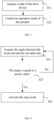
- the method includes the following steps 310 and 320.
- a state of the drive device is acquired.
- the state of the drive device may include the torque of the actuator, the angle between the movable end and the fixed end, or the like, which is not limited in the present application.
- an operation mode of the actuator is controlled.
- the operation mode of the actuator includes: a forward rotation mode, in which the movable end is pivoted away from the fixed end; a reverse rotation mode, in which the movable end is pivoted close to the fixed end; and a stop mode, in which a relative position between the movable end and the fixed end is maintained.
- the drive device when the actuator is in the forward rotation mode, the drive device can be switched from the closed state to the opened state.
- the actuator is in the reverse rotation mode, the drive device can be switched from the opened state to the closed state.
- the actuator is in the stop mode.
- the stop mode can be configured to maintain the drive device in the opened state or closed state, or to maintain the drive device in any desired state between the opened state and the closed state.
- the drive device can be adjusted intelligently and automatically to improve the flexibility and ease of use of the drive device. Moreover, adjusting the operation mode of the actuator according to the state of the drive device enables targeted adjustments to the actuator, which is conducive to ensuring the normal operation of the drive device.
- a method of controlling the drive device includes the following steps 410 to 430.
- step 410 the angle between the fixed end and the movable end is acquired.
- step 420 it is determined whether the angle is equal to a preset value. If not, the method returns to perform the step 410; and if yes, the method proceeds to the next step.
- the preset value may be a first preset value, which is a value of the angle between the movable end and the fixed end when the drive device is in the closed state, or the preset value may be a second preset value, which is a value of the angle between the movable end and the fixed end when the drive device is in the opened state.
- the stop mode is activated.
- a value of the angle between the fixed end and the movable end can be acquired in real time, and the operation mode of the actuator can be controlled to be the stop mode when the value of the angle is equal to the first preset value, thereby avoiding problems such as jamming between the movable end and the fixed end or damage to the actuator, caused by continued operation of the actuator when the movable end is pivoted to the closed position.
- the operation mode of the actuator can be controlled to be the stop mode when the value of the angle is equal to the second preset value, thereby avoiding the problem that the movable end is pivoted beyond the travel of movement and thus making it difficult for the movable end to be pivoted in reverse to the closed position, caused by continued operation of the actuator when the movable end is pivoted to the opened position.
- the preset value may also include both the first preset value and the second preset value, so as to stop the operation of the actuator in time when the drive device is pivoted to the fully closed state and to the fully opened state, which is not limited in the present application.
- a method of controlling the drive device includes the following steps 510 to 530.
- the torque of the actuator is acquired.
- the torque of the actuator may be configured to determine whether the actuator is in normal operation.
- step 520 it is determined whether the torque of the actuator is greater than a preset value. If not, the method returns to perform the step 510; and if yes, the method proceeds to the next step.
- the preset value may be a torque value of the actuator during normal operation.
- the torque of the actuator is greater than the preset value, it can be determined that there is an obstruction at the movable end when it is pivoted away from or close to the fixed end, and thus it can be indirectly determined that there is a foreign object or an obstacle that is preventing the normal operation of the drive device.
- the stop mode is activated.
- the pivoting movement of the drive device can be stopped in time, so as to avoid damage to the drive device caused by the continued forward rotation of the actuator when, for example, the drive device is pivoted to open (with the actuator rotated forward) and there is insufficient external space, or to avoid damage to the drive device and damage to a foreign object caused by the continued reverse rotation of the actuator when the drive device is pivoted to close (with the actuator rotated in reverse) and the foreign object is between the movable end and the fixed end.
- the foreign object may be an object that accidentally falls between the movable end and the fixed end from the outside, and the continued reverse rotation may result in damage to the object.
- the foreign object may even be a limb of a child, and the continued reverse rotation may result in personal injury. Therefore, the control method can improve the safety of the drive device to a certain extent.
- step 520 may be incorporated into step 510 or step 530.
- step 420 may be incorporated into step 410 or step 430, which is not limited in the present application.
- both the acquisition of the torque of the actuator and the acquisition of the angle between the fixed end and the movable end may be performed, enabling the control method to monitor both the torque of the actuator and the relative position between the movable end and the fixed end.
- the present application further provides a method of controlling the drive device, including the following steps 610 to 662.
- an initial operation mode of the actuator is acquired.
- the initial operation mode of the actuator may be a forward rotation mode, a reverse rotation mode, or a stop mode.
- a torque of the actuator is acquired.
- step 630 it is determined whether the torque of the actuator is greater than a preset value. If not, the method returns to perform the step 620; and if yes, the method proceeds to the next step.
- the preset value may be a torque value of the actuator during normal operation.
- the torque of the actuator is greater than the preset value, it can be determined that there is an obstruction at the movable end when it is pivoted away from or close to the fixed end, and thus it can be indirectly determined that there is a foreign object or an obstacle that is preventing the normal operation of the drive device.
- the stop mode is activated.
- controlling the actuator to be the stop mode in time upon determining that the torque of the actuator is greater than the preset value can avoid damage to the actuator and other structures of the drive device caused by the continued pivoting movement of the movable end.
- step 650 it is determined whether the initial operation mode is the forward rotation mode.
- the torque of the actuator is greater than the preset value before the stop mode is activated, it means that the actuator is in the forward rotation mode or the reverse rotation mode at this time. That is, the movable end is being pivoted away from the fixed end or is being pivoted close to the fixed end.
- step 661 the method performs step 661 in which the reverse rotation mode is activated.
- the reverse rotation mode is activated.
- the torque of the actuator is greater than the preset value during pivoting of the movable end away from the fixed end, the movable end stops pivoting and the actuator is rotated in reverse to pivot the movable end close to the fixed end.
- step 662 the method performs step 662 in which the forward rotation mode is activated.
- the initial operation mode of the actuator is either the forward rotation mode or the reverse rotation mode at this time. If the initial operation mode of the actuator is not the forward rotation mode, it means that the initial operation mode of the actuator is the reverse rotation mode, at which time the forward rotation mode is activated. In other words, if the torque of the actuator is greater than the preset value during the pivoting of the movable end close to the fixed end, the movable end stops pivoting and the actuator is rotated forward to pivot the movable end away from the fixed end.
- the method may return to step 620 and re-determine whether or not the actuator is operated abnormally in the changed operation mode, so as to maintain real-time monitoring of the torque of the actuator and to avoid abnormal operation of the actuator in the changed operation mode.
- step 650 it may also be determined whether the initial operation mode is the reverse rotation mode. And accordingly, if yes, the method performs step 662; and if not, the method performs step 661.
- the initial operation mode is the reverse rotation mode or the forward rotation mode. If it is the reverse rotation mode, the method performs step 662; and if it is the forward rotation mode, the method performs step 661.
- the present application further provides a method of controlling the drive device, including the following steps 710 to 792.
- an initial operation mode of the actuator is acquired.
- a number of abnormalities N is set and N is made equal to 0.
- the number of abnormalities may be configured to record the number of abnormalities in terms of the torque of the actuator.
- a torque of the actuator is acquired.
- step 740 it is determined whether the torque of the actuator is greater than a preset value. If not, the method returns to perform the step 730; and if yes, the method proceeds to the next step.
- the stop mode is activated.
- step 760 it is determined whether the number of abnormalities N is greater than 0.
- step 761 the method performs step 761 in which the stop mode is maintained.
- step 770 the method performs step 770 in which N is increased by 1, and the method proceeds to the next step.
- the actuator has been operated abnormally before.
- the drive device may have encountered an obstruction during the opening process, at which point N is 0.
- the actuator executes a reverse rotation instruction to close the drive device, at which point N is 1.
- N is greater than zero, and the actuator executes a stop instruction.
- step 780 it is determined whether the initial operation mode is the reverse rotation mode.
- step 791 the method performs step 791 in which the forward rotation mode is activated.
- step 792 the method performs step 792 in which the reverse rotation mode is activated.
- the method may return to step 730 and re-determine whether or not the actuator is operated abnormally in the changed operation mode, so as to maintain real-time monitoring of the torque of the actuator and to avoid abnormal operation of the actuator in the changed operation mode.
- step 780 it may also be determined whether the initial operation mode is the forward rotation mode. And accordingly, if yes, the method performs step 792; and if not, the method performs step 791.
- step 780 it may also be determined whether the initial operation mode is the reverse rotation mode or the forward rotation mode. If it is the reverse rotation mode, the method performs step 791; and if it is the forward rotation mode, the method performs step 792.
- the present application is not limited thereto.
Landscapes
- Engineering & Computer Science (AREA)
- Mechanical Engineering (AREA)
- Power-Operated Mechanisms For Wings (AREA)
Abstract
Description
- The present application relates to the field of vehicle technology, and in particular to a drive device, a vehicle, and a method of controlling a drive device.
- With the rapid development of the vehicle industry, consumers have increasingly high demands for vehicle automation. Manual opening or closing of trunk doors of vehicles in the past can no longer meet the current consumer demand for vehicle functionality.
- At present, more and more vehicles have trunk doors formed by a combination of upper and lower tailgates. The lower tailgate, when opened, can expand the trunk space, providing users with more ways to use it in different scenarios.
- The present application provides a drive device, a vehicle, and a method of controlling a drive device.
- A first aspect of the present application provides a drive device, including an articulated structure, a transmission structure, and a drive structure. The articulated structure includes a fixed end and a movable end articulatedly connected to the fixed end. The transmission structure is provided at the movable end and includes a connecting rod and a rocker arm. One end of the connecting rod is rotatably connected to the rocker arm, and the other end of the connecting rod is rotatably connected to the fixed end. The drive structure is provided at the movable end and includes an actuator and a drive shaft. The drive shaft is fixedly connected to an end of the rocker arm away from the connecting rod. The actuator drives the drive shaft to rotate the rocker arm about an axis of the drive shaft. Due to a stable output torque of the actuator, the rocker arm is driven by the actuator to rotate non-linearly, such that the connecting rod pushes the movable end to pivot, which is conducive to overcoming the problem of constant change in the force arm of the drive device during opening and closing, and improves the stability of the drive device during the opening and closing.
- Further, the drive structure includes a driving gear and a driven gear. The driving gear is connected to the actuator. The driven gear meshes with the driving gear and is fixedly connected to the drive shaft, where the driving gear has a diameter smaller than that of the driven gear. A reduction ratio between the driving gear and the driven gear enables the driven gear to amplify the torque of the actuator, which is conducive to reducing the requirements for parameters of the actuator, and thus reducing the size and cost of the actuator, as compared to the case in which the actuator is directly connected to the drive shaft.
- Further, the driven gear includes a first driven gear and a second driven gear, the first driven gear meshing with the driving gear and the second driven gear, respectively, and the second driven gear being fixedly connected to the drive shaft, where the first driven gear has a diameter larger than that of the driving gear and smaller than that of the second driven gear. In this way, it is possible to avoid the need for a huge driven gear due to an excessive reduction ratio in the case of one-stage gear transmission, which is conducive to optimizing the volume of the drive device.
- Further, the first driven gear includes a first sub-gear and a second sub-gear, where the first sub-gear is fixedly connected to the second sub-gear, and the first sub-gear has a diameter larger than that of the second sub-gear; and the first sub-gear meshes with the driving gear, and the second sub-gear meshes with the second driven gear. In this way, multiple gears can be arranged in different planes, making full use of multiple dimensions of space in the drive device, improving the compactness of the structure, and optimizing the utilization of space.
- Further, the drive device further includes a sealing sleeve. The sealing sleeve is disposed around a portion of the connecting rod, and one end of the sealing sleeve is fixedly connected to the connecting rod, and the other end of the sealing sleeve extends to the movable end. In this way, even if impurities enter the drive device, the sealing sleeve can keep the impurities out of the drive structure and the transmission structure, preventing the impurities from affecting the drive structure and the transmission structure.
- Further, an end of the connecting rod close to the rocker arm includes a first socket, and an end of the rocker arm close to the connecting rod includes a first ball, the first ball being rotatably disposed in the first socket; and/or an end of the connecting rod close to the fixed end includes a second socket, and the fixed end includes a second ball, the second ball being rotatably disposed in the second socket. With the contact between spherical surfaces, an angle of rotation between the connecting rod and the rocker arm increases, so as to enable rotation in multiple directions, which improves the rotation flexibility of the drive device at rotatable connection positions during opening or closing, making the movement of the drive device smoother.
- Further, the drive device further includes a torque sensor configured to detect the torque of the actuator. In this way, it is possible to avoid damage to the actuator as well as personal injury and damage to foreign objects, due to catching of the objects during pivoting of the movable end close to the fixed end.
- A second aspect of the present application provides a vehicle, including a door assembly and the drive device as described in the preceding first aspect, where the drive device is configured to drive the door assembly to open or close. By providing the drive device, the actuator drives the rocker arm to rotate non-linearly to drive the connecting rod to push the movable end to pivot away from or close to the fixed end, thereby enabling automatic opening and closing of the door assembly. Moreover, the actuator has a stable torque output, which can effectively improve the stability of the angle change of the door assembly during opening and closing.
- Further, the vehicle further includes a vehicle body, and the door assembly includes a lower tailgate. The movable end of the articulated structure of the drive device is fixedly connected to the lower tailgate, and the fixed end of the articulated structure is fixedly connected to the vehicle body. In this way, the lower tailgate has a uniform change in force during opening and closing process by pivoting, such that the lower tailgate can be opened and closed smoothly at a uniform speed, improving the stability of the opening and closing process.
- Further, the vehicle further includes a locking structure and a locking sensor. The locking structure includes a vehicle body locking member and a lower tailgate locking member cooperating with the vehicle body locking member, and the locking sensor is configured to detect a locking state between the vehicle body locking member and the lower tailgate locking member. By providing the locking sensor, it is possible to detect whether the lower tailgate locking member and the vehicle body locking member are locked together, thereby detecting whether the drive device is pivoted in place and switched to a closed state, and avoiding accidental opening of the lower tailgate caused by the drive device not being closed in place.
- A third aspect of the present application provides a method of controlling a drive device, applied to the vehicle as described in the preceding second aspect, the method including: acquiring a state of the drive device; and controlling an operation mode of the actuator, where the operation mode includes: a forward rotation mode, in which the movable end is pivoted away from the fixed end; a reverse rotation mode, in which the movable end is pivoted close to the fixed end; and a stop mode, in which a relative position between the movable end and the fixed end is maintained. By acquiring the state of the drive device and then controlling the operation mode of the actuator, the drive device can be adjusted intelligently and automatically to improve the flexibility and ease of use of the drive device.
- Further, acquiring the state of the drive device includes: acquiring a torque of the actuator; and controlling the operation mode of the actuator includes: activating the stop mode in response to the torque of the actuator being greater than a preset value. In this way, when the torque of the actuator is greater than the preset value, the pivoting movement of the drive device can be stopped in time, so as to avoid damage to the drive device caused by the continued forward rotation of the actuator when, for example, the drive device is pivoted to open (with the actuator rotated forward) and there is insufficient external space, or to avoid damage to the drive device and damage to a foreign object caused by the continued reverse rotation of the actuator when the drive device is pivoted to close (with the actuator rotated in reverse) and the foreign object is between the movable end and the fixed end.
- Further, the method further includes: before acquiring the state of the drive device, acquiring an initial operation mode of the actuator, and the method further includes: after activating the stop mode, determining whether the initial operation mode is the forward rotation mode or the reverse rotation mode; activating the reverse rotation mode in response to determining that the initial operation mode is the forward rotation mode; and activating the forward rotation mode in response to determining that the initial operation mode is the reverse rotation mode. In this way, if there is an obstacle during the opening of the drive device, the actuator will be rotated in reverse to close the drive device, so as to avoid collision between the protruding movable end and the obstacle, resulting in damage to the obstacle or the movable end. If there is an obstacle during the closing of the drive device, the actuator will be rotated forward to open the drive device, so as to prevent the drive device from maintaining the catching of the obstacle.
- Further, the method further includes: before acquiring the torque of the actuator, setting a number of abnormalities N and making N equal to 0; and the method further includes: before determining whether the initial operation mode is the forward rotation mode or the reverse rotation mode, determining whether the number of abnormalities N is greater than 0; maintaining the stop mode in response to N being greater than 0; and increasing N by 1 in response to N being not greater than 0.
- Further, acquiring the state of the drive device includes: acquiring an angle between the fixed end and the movable end; and controlling the operation mode of the actuator includes: activating the stop mode in response to the angle reaching a preset value. In this way, a value of the angle between the fixed end and the movable end can be acquired in real time, and the operation mode of the actuator can be controlled to be the stop mode when the value of the angle is equal to the preset value, thereby avoiding problems such as jamming between the movable end and the fixed end or damage to the actuator, caused by continued operation of the actuator when the movable end is pivoted to the closed or opened position.
- It should be understood that the above general description and the following detailed description are exemplary and explanatory only, and are not intended to limit the present application.
- In order to more clearly illustrate embodiments of the present application, the accompanying drawings to be used in the description of the embodiments will be briefly described below. Obviously, the drawings in the following description merely illustrate some of the embodiments of the present application, and other drawings may be obtained from these drawings by those ordinary skilled in the art without any creative efforts.
-
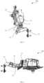
FIG. 1 is a front view illustrating a drive device according to an embodiment of the present application. -
FIG. 2 is a rear view illustrating the drive device as shown inFIG. 1 . -
FIG. 3 is a side view illustrating the drive device as shown inFIG. 1 in a closed state. -
FIG. 4 is a side view illustrating the drive device as shown inFIG. 1 in an opened state. -
FIG. 5 is a schematic partial view illustrating a vehicle according to an embodiment of the present application, in which a lower tailgate is in a closed state. -
FIG. 6 is a schematic partial view illustrating the vehicle as shown inFIG. 5 , in which the lower tailgate is in an opened state. -
FIG. 7 is a schematic flowchart illustrating a method of controlling a drive device according to an embodiment of the present application. -
FIG. 8 is a schematic flowchart illustrating a method of controlling a drive device according to another embodiment of the present application. -
FIG. 9 is a schematic flowchart illustrating a method of controlling a drive device according to still another embodiment of the present application. -
FIG. 10 is a schematic flowchart illustrating a method of controlling a drive device according to yet another embodiment of the present application. -
FIG. 11 is a schematic flowchart illustrating a method of controlling a drive device according to yet another embodiment of the present application. - 100 drive device, 1 articulated structure, 11 movable end, 111 connecting rod hole, 12 fixed end, 13 pivot axis, 2 transmission structure, 21 connecting rod, 22 rocker arm, 3 drive structure, 31 actuator, 32 drive shaft, 33 driving gear, 34 driven gear, 341 first driven gear, 342 second driven gear, 343 first sub-gear, 344 second sub-gear, 4 sealing sleeve, 51 first fixing plate, 52 second fixing plate, 200 vehicle, 210 vehicle body, 220 lower tailgate, 230 upper tailgate, 240 trunk space.
- Reference will now be made in detail to exemplary embodiments, examples of which are illustrated in the accompanying drawings. When the following description refers to the drawings, the same numerals in different drawings indicate the same or similar elements, unless otherwise indicated. Modes described in the following exemplary embodiments are not intended to be representative of all modes consistent with the present application. Rather, they are merely examples of devices and methods consistent with some aspects of the present application as detailed in the appended claims.
- Terminology used herein is for the purpose of describing particular embodiments only, and is not intended to be limiting of the present application. Unless otherwise defined, technical or scientific terms used herein shall have their ordinary meanings as understood by a person of ordinary skill in the art to which the present application pertains. Terms "first," "second," and the like as used in the specification and claims of the present application do not imply any order, quantity, or importance, but are merely used to distinguish one component from another. Similarly, terms "a" or "an" and the like do not denote a limitation on quantity, but rather denote the presence of at least one, which would be stated separately if they referred only to "one". "A plurality of' or "multiple" means two or more. Unless otherwise indicated, terms "front," "rear," "lower," and/or "upper" and the like are for convenience of description only, and are not limited to a position or a spatial orientation. Terms "including" or "comprising" and the like are intended to mean that elements or items appearing before "including" or "comprising" encompass elements or items listed after "including" or "comprising" and equivalents thereof, without excluding other elements or items. Terms "connected" or "coupled" and the like are not limited to physical or mechanical connections, but may include electrical connections, whether direct or indirect. As used in the specification and the appended claims of the present application, the singular forms of "a," "an," "the," and "said" are intended to include plural forms as well, unless the context clearly dictates otherwise. It should also be understood that the term "and/or" as used herein refers to and includes any or all possible combinations of one or more of the associated listed items.
- Referring to
FIG. 1 to FIG. 4 , a first aspect of the present application provides adrive device 100, including an articulatedstructure 1, atransmission structure 2, and a drive structure 3. The articulatedstructure 1 includes afixed end 12 and amovable end 11 articulatedly connected to thefixed end 12. Thetransmission structure 2 and the drive structure 3 are both provided at themovable end 11. Thetransmission structure 2 includes a connectingrod 21 and arocker arm 22. One end of the connectingrod 21 is rotatably connected to therocker arm 22, and the other end of the connectingrod 21 is rotatably connected to thefixed end 12. The drive structure 3 includes anactuator 31 and adrive shaft 32. Thedrive shaft 32 is fixedly connected to an end of therocker arm 22 away from the connectingrod 21, and theactuator 31 drives thedrive shaft 32 to rotate therocker arm 22 about an axis of thedrive shaft 32. - The
drive device 100 includes a closed state and an opened state. The closed state is shown inFIG. 3 , where an angle between themovable end 11 and thefixed end 12 is small and the connectingrod 21 is in an approximately vertical state. The opened state is shown inFIG. 4 , where the angle between themovable end 11 and thefixed end 12 increases and the connectingrod 21 is in an approximately horizontal state. - Referring to
FIG. 1 , thedrive device 100 is in the closed state. When thedrive device 100 is switched from the closed state to the opened state, theactuator 31 drives thedrive shaft 32 to rotate, such that an end of therocker arm 22 connected to the connectingrod 21 moves downward. Since the other end of the connectingrod 21 is connected to thefixed end 12, which has a constant position, and the connectingrod 21 has a fixed length, the force originally exerted on thefixed end 12 by the connectingrod 21 is exerted on themovable end 11 in reverse, such that themovable end 11 is pivoted away from the fixedend 12 around apivot axis 13. In this way, thedrive device 100 can be switched from the closed state to the opened state. - On the contrary, when the
drive device 100 is in the opened state, theactuator 31 drives thedrive shaft 32 to rotate in a reverse direction, and the connectingrod 21 has a tendency to pull thefixed end 12. Due to the fixed position of thefixed end 12, the connectingrod 21 pulls up themovable end 11 in a reverse direction, such that themovable end 11 is pivoted close to thefixed end 12 around thepivot axis 13, thereby switching thedrive device 100 from the opened state to the closed state. - In this way, the
rocker arm 22 is driven by theactuator 31 with a stable output torque to rotate non-linearly, such that the connectingrod 21 pushes themovable end 11 to pivot, which is conducive to overcoming the problem of constant change in the force arm of thedrive device 100 during opening and closing, and improves the stability of thedrive device 100 during the opening and closing. Moreover, when thedrive device 100 is switched between the opened state and the closed state, the connectingrod 21 can be switched from an approximately vertical state to an approximately horizontal state, and thus drive themovable end 11 to pivot relative to thefixed end 12 at a pivot angle in a range greater than or equal to 0° and less than or equal to 120°, enabling full opening and closing of thedrive device 100. - In addition, referring to
FIG. 3 and FIG. 4 , when thedrive device 100 is pivoted to a limit opened position, a change in the angle between themovable end 11 and thefixed end 12 reaches more than 100°, while a change in the angle of the connectingrod 21 is less than 80° or even 70°. In other words, the connectingrod 21 and therocker arm 22 only need to be moved by a small amplitude to realize the complete opening and complete closing of thedrive device 100. Therefore, the movement amplitude of thetransmission structure 2 can be amplified with the arrangement of the present application, without reserving a large travel space for thetransmission structure 2, thereby optimizing the volume of thetransmission structure 2. - The
rocker arm 22 may have a rod-like structure similar to the connectingrod 21. Alternatively, therocker arm 22 may have a droplet-shaped structure as shown inFIG. 1 , with a portion having a larger radius disposed on thedrive shaft 32. A center line of therocker arm 22 intersects the axis of thedrive shaft 32, allowing the end of therocker arm 22 close to the connectingrod 21 to make an arcuate trajectory as thedrive shaft 32 rotates. When the connectingrod 21 exerts the force on therocker arm 22 in reverse, the end of therocker arm 22 close to thedrive shaft 32 is subjected to a greater bending moment. In this way, the strength of therocker arm 22 can be improved to avoid breakage of therocker arm 22 during operation of thedrive device 100. Moreover, as compared to the case where therocker arm 22 is provided with a structure having a uniform width, the droplet-shaped structure can save material for therocker arm 22, and also reduce the overall weight of thedrive device 100. - An angle between the connecting
rod 21 and therocker arm 22, and an angle between the connectingrod 21 and thefixed end 12 are changed during the opening and closing of thedrive device 100. In order to better realize the relative movement between the connectingrod 21 and therocker arm 22, and between the connectingrod 21 and thefixed end 12, the end of the connectingrod 21 close to therocker arm 22 includes a first socket (not shown), the end of therocker arm 22 close to the connectingrod 21 includes a first ball (not shown), and the first ball is rotatably disposed in the first socket. Similarly, the end of the connectingrod 21 close to thefixed end 12 includes a second socket (not shown), thefixed end 12 includes a second ball (not shown), and the second ball is rotatably disposed in the second socket. With the contact between spherical surfaces, an angle of rotation between the connectingrod 21 and therocker arm 22 increases, so as to enable rotation in multiple directions, which improves the rotation flexibility of thedrive device 100 at rotatable connection positions during the opening or closing, making the movement of thedrive device 100 smoother. - In other embodiments, the
rocker arm 22 and thefixed end 12 may be provided with a socket, and the connectingrod 21 may be provided with a ball. Alternatively, one of therocker arm 22 and the connectingrod 21 may be provided with a ball, and the other of therocker arm 22 and the connectingrod 21 may be provided with a bearing, which is not limited in the present application. It should be noted that the manner in which therocker arm 22 and the connectingrod 21 are connected may be the same or different from the manner in which the connectingrod 21 and thefixed end 12 are connected. By way of example, therocker arm 22 may include a first socket, and the connectingrod 21 may be provided with a corresponding first ball, while a second ball may be provided at the other end of the connectingrod 21, and a bearing may be provided at thefixed end 12, which is not limited in the present application. - In some embodiments, a connecting
rod hole 111 is provided at themovable end 11, such that the connectingrod 21 passes through the connectingrod hole 111 and is connected to thefixed end 12. When thedrive device 100 is switched from the opened state to the closed state or from the closed state to the opened state, the connectingrod 21 can be moved in the connectingrod hole 111, so as to avoid interference with the movement of themovable end 11. Moreover, the arrangement in which the connectingrod 21 passes through themovable end 11 can also improve the compactness of the structure, which is conducive to reducing the volume occupied by thedrive device 100. However, in other embodiments, it is possible to change the shape of themovable end 11 to provide themovable end 11 with an avoidance portion (not shown), so as to avoid the range of movement of the connectingrod 21 as a whole, but the present application is not limited thereto. - In addition, based on the above description, the
drive device 100 according to the present application can amplify the movement amplitude of thetransmission structure 2, and the connectingrod 21 and therocker arm 22 only need to be moved by a small amplitude to realize the complete opening and complete closing of thedrive device 100. Therefore, due to the relatively small movement amplitude of the connectingrod 21, thedrive device 100 according to the present application can be provided with a small connectingrod hole 111 or avoidance portion, such that themovable end 11 has higher strength while reducing the overall size of themovable end 11. - In some embodiments, the
actuator 31 may be directly connected to thedrive shaft 32, such that theactuator 31 can directly drive thedrive shaft 32 to rotate, simplifying the structure of thedrive device 100, and preventing thedrive device 100 from occupying too much space. In other embodiments, the drive structure 3 includes adriving gear 33 connected to theactuator 31, and a drivengear 34 meshing with thedriving gear 33. The drivengear 34 is fixedly connected to thedrive shaft 32, and the drivengear 34 has a diameter larger than that of thedriving gear 33. In this way, thedrive shaft 32 is indirectly connected to theactuator 31. Theactuator 31 drives thedriving gear 33 to rotate, such that the drivengear 34, which meshes with thedriving gear 33, drives thedrive shaft 32 to rotate. A reduction ratio between the drivinggear 33 and the drivengear 34 enables the drivengear 34 to amplify a torque of theactuator 31, which is conducive to reducing the requirements for parameters of theactuator 31, and thus reducing the size and cost of theactuator 31, and indirectly optimizing the size and cost of thedrive device 100, as compared to the case in which theactuator 31 is directly connected to thedrive shaft 32. - In order to control the sizes of the driven
gear 34 and thedriving gear 33 so as to optimize the size of thedrive device 100, in some embodiments, the drivengear 34 includes a first drivengear 341 and a second drivengear 342. The first drivengear 341 meshes with thedriving gear 33 and the second drivengear 342, respectively, and the second drivengear 342 is fixedly connected to thedrive shaft 32. The first drivengear 341 has a diameter larger than that of thedriving gear 33 and smaller than that of the second drivengear 342. By means of multi-stage gear transmission, a first stage of reduction can be completed between the drivinggear 33 and the first drivengear 341 to realize a first torque increase, and a second stage of reduction can be completed between the first drivengear 341 and the second drivengear 342 to realize a second torque increase. In this way, it is possible to avoid the need for a huge drivengear 34 due to an excessive reduction ratio in the case of one-stage gear transmission, which is conducive to optimizing the size of thedrive device 100. - In order for further space optimization for the
drive device 100, in some embodiments, the first drivengear 341 includes afirst sub-gear 343 and asecond sub-gear 344. Thefirst sub-gear 343 is fixedly connected to thesecond sub-gear 344, and has a diameter larger than that of thesecond sub-gear 344. The first sub-gear 343 meshes with thedriving gear 33, and the second sub-gear 344 meshes with the second drivengear 342. Thefirst sub-gear 343 is fixedly connected to thesecond sub-gear 344, such that when thedriving gear 33 meshes with thefirst sub-gear 343 and rotates, thesecond sub-gear 344 rotates along with thefirst sub-gear 343, to drive the second drivengear 342 to rotate. By arranging thefirst sub-gear 343 and thesecond sub-gear 344, a reduction ratio between the drivinggear 33 and the first drivengear 341, and a reduction ratio between the first drivengear 341 and the second drivengear 342 remain unchanged. However, since the second drivengear 342 meshes with the smallersecond sub-gear 344, a distance between an axis of rotation of the second drivengear 342 and an axis of rotation of the first drivengear 341 is reduced. In other words, orthographic projections of the second drivengear 342 and the first drivengear 341 on a plane of rotation of the gear such as thedriving gear 33 partially overlap with each other. Therefore, instead of simply laying multiple gears flat in the same plane, the multiple gears can be arranged in different planes, making full use of multiple dimensions of space in thedrive device 100, improving the compactness of the structure, and optimizing the utilization of space. - However, in other embodiments, the
transmission structure 2 may adopt a chain transmission, a belt transmission, or other transmission, which is not limited in the present application. - In addition, the
drive device 100 may further include a lubricating layer (not shown). The lubricating layer may be provided in thetransmission structure 2, for example, on gear teeth of thedriving gear 33 and the drivengear 34, or may be provided at a connection position between the connectingrod 21 and therocker arm 22, which is not limited in the present application. By providing a lubricating layer between two parts that are in contact with each other and move relative to each other, it is possible to improve the smoothness of thedrive device 100 during the opening and closing, avoid sharp noise caused by friction between parts to affect the user experience, and avoid friction fatigue of parts due to long-term friction, such that the service life of thedrive device 100 can be prolonged to a certain extent. - In some embodiments, the
drive device 100 further includes afirst fixing plate 51 for fixing the drive structure 3. Thefirst fixing plate 51 is connected to themovable end 11, such that the drive structure 3 is indirectly connected to themovable end 11. Theactuator 31 is disposed on one side of thefirst fixing plate 51, therocker arm 22 is disposed on the other side of thefirst fixing plate 51, and thedrive shaft 32 passes through thefirst fixing plate 51 so as to connect theactuator 31 and therocker arm 22. Providing thefirst fixing plate 51 can facilitate assembly. The drive structure 3 and thetransmission structure 2 can be assembled on thefirst fixing plate 51, and then thefirst fixing plate 51 can be connected to themovable end 11 so as to realize connection among various structures. However, in other embodiments, thefirst fixing plate 51 and themovable end 11 can be integrally formed, which is not limited in the present application. - In the embodiment where the
drive device 100 includes a drivengear 34 and adriving gear 33, a chain transmission structure, or a belt transmission structure, in order to further fix the drive structure 3, thedrive device 100 may further include asecond fixing plate 52 arranged parallel to thefirst fixing plate 51 and connected to thefirst fixing plate 51. Theactuator 31 is disposed on a side of thefirst fixing plate 51 away from thesecond fixing plate 52, and structures such as the drivengear 34 and thedriving gear 33 are disposed between thefirst fixing plate 51 and thesecond fixing plate 52. In this way, the drivengear 34 and thedriving gear 33 can remain in a fixed position by thefirst fixing plate 51 and thesecond fixing plate 52. Even if the drivengear 34 and thedriving gear 33 tend to deviate from their positions by gravity when the angle of themovable end 11 is changed, thefirst fixing plate 51 and thesecond fixing plate 52 can hold against the drivengear 34 and thedriving gear 33. - The
first fixing plate 51 and thesecond fixing plate 52 may be flat plates. Alternatively, in some embodiments, one of thefirst fixing plate 51 and thesecond fixing plate 52 is a flat plate, and the other of thefirst fixing plate 51 and thesecond fixing plate 52 is a plate with a receiving cavity (not shown) provided in the middle. In this way, thefirst fixing plate 51 and thesecond fixing plate 52 can realize a fit connection around the perimeter thereof, and the receiving cavity is configured to receive the drivengear 34 and thedriving gear 33. By such an arrangement, a sealed space can be provided for the drivengear 34 and thedriving gear 33, and drive abnormalities caused by the tendency of foreign objects to be caught during the gear meshing due to rotation can be avoided. In addition, it is also possible to avoid the influence of external dust, water and other impurities on the lubricating layer and meshing of the gears. However, in other embodiments, each of thefirst fixing plate 51 and thesecond fixing plate 52 may be provided with a respective receiving half-cavity, and after thefirst fixing plate 51 and thesecond fixing plate 52 are in fit connection around the perimeter thereof, two receiving half-cavities form a complete receiving cavity, but the present application is not limited thereto. - After the
drive device 100 is opened, the angle between themovable end 11 and thefixed end 12 increases, at which time impurities are prone to enter theactuator 31 and thetransmission structure 2 through a gap between the connectingrod 21 and themovable end 11, negatively affecting thedrive device 100. In order to improve the sealing protection for theactuator 31 and thetransmission structure 2, and to prevent impurities such as water and dust from entering the drive structure 3 during the opening and closing of thedrive device 100, which may lead to, for example, failure of the lubricating layer and short-circuiting of theactuator 31, thedrive device 100 according to the present application further includes a sealingsleeve 4. The sealingsleeve 4 is disposed around a portion of the connectingrod 21, and one end of the sealingsleeve 4 is fixedly connected to the connectingrod 21, and the other end of the sealingsleeve 4 extends to themovable end 11. By such an arrangement, even if the impurities enter into thedrive device 100, the sealingsleeve 4 can keep the impurities out of the drive structure 3 and thetransmission structure 2, preventing the impurities from influencing the drive structure 3 and thetransmission structure 2. The sealingsleeve 4 may also be fixedly connected to themovable end 11, for example, by bonding or the like, so as to seal a gap between themovable end 11 and the sealingsleeve 4, further improving the sealing performance of the sealingsleeve 4. - In some embodiments, the sealing
sleeve 4 may be made of an elastic material, enabling stretching and retracting of the sealingsleeve 4 during movement of the connectingrod 21. In other embodiments, the sealingsleeve 4 may be provided with a multi-layer foldable structure, enabling the stretching and retracting of the sealingsleeve 4 by unfolding and folding of the multi-layer foldable structure during the movement of the connectingrod 21, which is not limited in the present application. - As the
drive device 100 is switched from the opened state to the closed state, or from the closed state to the opened state, the angle between themovable end 11 and thefixed end 12 may be changed. In order to avoid damage to theactuator 31, personal injury and damage to foreign objects due to catching of the objects during the pivoting of themovable end 11 close to thefixed end 12, in some embodiments, thedrive device 100 further includes a torque sensor to detect the torque of theactuator 31. In the event that the torque of theactuator 31 increases, it can be determined that thedrive device 100 is catching a foreign object. Therefore, the operation of theactuator 31 may be stopped subsequently to avoid damage to persons and objects caused by thedrive device 100, which can improve the safety of thedrive device 100. - Based on the various embodiments as described above, with reference to
FIGS. 5 and 6 , a second aspect of the present application provides avehicle 200 including a door assembly and thedrive device 100 as described in the preceding first aspect, where thedrive device 100 is configured to drive the door assembly to open or close. Thedrive device 100 may be provided at the door assembly such as a vehicle door, a trunk door, or a front hood, which is not limited in the present application. By providing thedrive device 100, theactuator 31 drives therocker arm 22 to rotate non-linearly to drive the connectingrod 21 to push themovable end 11 to pivot away from or close to thefixed end 12, thereby enabling automatic opening and closing of the door assembly. Moreover, theactuator 31 has a stable torque output, which can effectively improve the stability of the angle change of the door assembly during opening and closing. - In some embodiments, the
vehicle 200 is provided with avehicle body 210, and the door assembly includes alower tailgate 220. Themovable end 11 of thedrive device 100 is fixedly connected to thelower tailgate 220, and thefixed end 12 is fixedly connected to thevehicle body 210. Therefore, when theactuator 31 drives therocker arm 22 to rotate, the connectingrod 21 pushes thefixed end 12, and since thefixed end 12 is fixed to thevehicle body 210 and is difficult to move, the connectingrod 21 exerts the force on themovable end 11 in reverse, causing themovable end 11 to drive thelower tailgate 220 to pivot away from thevehicle body 210, thereby enabling the opening of thelower tailgate 220. On the contrary, when theactuator 31 drives therocker arm 22 to rotate in a reverse direction, the connectingrod 21 applies a pull force to thefixed end 12, and since thefixed end 12 is immovable, the connectingrod 21 exerts the pull force on themovable end 11 in reverse, causing themovable end 11 to drive thelower tailgate 220 to pivot close to thevehicle body 210, thereby enabling the closing of thelower tailgate 220. - In this way, the
lower tailgate 220 has a uniform change in force during the opening and closing process by pivoting, such that thelower tailgate 220 can be opened and closed smoothly at a uniform speed, improving the stability of the opening and closing process. Moreover, since themovable end 11 is pivoted relative to thefixed end 12 at a pivot angle ranging from 0° to 120°, thelower tailgate 220 can be fully opened. Thelower tailgate 220, when opened, can expand the usable space of the trunk, providing users with more use possibilities, so as to meet the user requirements in different scenarios. - In some embodiments, the
drive device 100 may be partially exposed from thelower tailgate 220 for ease of assembly and maintenance. In other embodiments, thedrive device 100 is entirely hidden inside thelower tailgate 220, which can to a certain extent seal thedrive device 100 through a shell of thelower tailgate 220, avoiding impurities from directly contacting the drive structure 3 and thetransmission structure 2, resulting in a negative impact on the operation of thedrive device 100. In addition, thehidden drive device 100 can not only improve the aesthetics of thelower tailgate 220 to avoid a bad visual impression caused by direct exposure of thedrive device 100, but also avoid the occupation of space in the trunk. - In the embodiment where the
drive device 100 includes the sealingsleeve 4, the shell of thelower tailgate 220 can be clamped to an end of the sealingsleeve 4 close to themovable end 11. In this way, even if impurities enter thedrive device 100 through the gap between themovable end 11 and the sealingsleeve 4, the flexible connection between thelower tailgate 220 and the sealingsleeve 4, acting as a second assurance, can prevent the impurities from further entering into thedrive device 100. - In addition, the
drive device 100 may include a plurality of articulatedstructures 1. For example, in the case of thelower tailgate 220, the plurality of articulatedstructures 1 may be evenly distributed in thepivot axis 13, and the drive structure 3 is connected to one of the articulatedstructures 1. When the drive structure 3 drives the articulatedstructure 1 to pivot, themovable end 11 drives thelower tailgate 220 to pivot, causing the movable ends 11 of the other articulatedstructures 1 to pivot along with it. By providing the plurality of articulatedstructures 1, it is possible to improve the strength for supporting thelower tailgate 220, as well as the stability of the force on thelower tailgate 220 during opening and closing. - It should be noted that the
vehicle 200 may include thelower tailgate 220 and anupper tailgate 230 as shown inFIGS. 5 and 6 , thereby enabling opening and closing of atrunk space 240. Moreover, theupper tailgate 230 may also be provided with thedrive device 100 according to the present application, which is not limited in the present application. However, thevehicle 200 may be a vehicle such as a pickup truck, or a van, that includes only thelower tailgate 220, which is not limited in the present application. - In some embodiments, the
vehicle 200 further includes a locking structure (not shown) and a locking sensor (not shown). The locking structure includes a vehicle body locking member and a lower tailgate locking member cooperating with the vehicle body locking member. The locking sensor is configured to detect a locking state between the vehicle body locking member and the lower tailgate locking member. By providing the locking sensor, it is possible to detect whether the lower tailgate locking member and the vehicle body locking member are locked together, thereby detecting whether thedrive device 100 is pivoted in place and switched to the closed state, and avoiding accidental opening of the lower tailgate caused by thedrive device 100 not being closed in place. Moreover, it is possible to stop the operation of theactuator 31 when the lower tailgate locking member and the vehicle body locking member are locked in place, thereby avoiding undesired opening of the lower tailgate caused by abnormal operation of theactuator 31. - In the embodiment where the
drive device 100 includes the torque sensor, it is also possible to perform timely detection and alarm when the lower tailgate is opened abnormally due to insufficient external space during the opening of the lower tailgate, or when an object or even a person is caught during the closing of the lower tailgate, to avoid impacts on the lower tailgate, the object, the person, and theactuator 31. - Referring to
FIG. 7 , a third aspect of the present application further provides a method of controlling a drive device, applicable to thevehicle 200 as described in the preceding second aspect. The method includes the followingsteps - At
step 310, a state of the drive device is acquired. - In this embodiment, the state of the drive device may include the torque of the actuator, the angle between the movable end and the fixed end, or the like, which is not limited in the present application.
- At
step 320, an operation mode of the actuator is controlled. - In this embodiment, the operation mode of the actuator includes: a forward rotation mode, in which the movable end is pivoted away from the fixed end; a reverse rotation mode, in which the movable end is pivoted close to the fixed end; and a stop mode, in which a relative position between the movable end and the fixed end is maintained.
- In other words, when the actuator is in the forward rotation mode, the drive device can be switched from the closed state to the opened state. When the actuator is in the reverse rotation mode, the drive device can be switched from the opened state to the closed state. When no action is required from the actuator, the actuator is in the stop mode. The stop mode can be configured to maintain the drive device in the opened state or closed state, or to maintain the drive device in any desired state between the opened state and the closed state.
- By acquiring the state of the drive device and then controlling the operation mode of the actuator, the drive device can be adjusted intelligently and automatically to improve the flexibility and ease of use of the drive device. Moreover, adjusting the operation mode of the actuator according to the state of the drive device enables targeted adjustments to the actuator, which is conducive to ensuring the normal operation of the drive device.
- An embodiment in which the state of the drive device is the angle between the movable end and the fixed end will be described below. Referring to
FIG. 8 , a method of controlling the drive device includes the followingsteps 410 to 430. - At
step 410, the angle between the fixed end and the movable end is acquired. - At
step 420, it is determined whether the angle is equal to a preset value. If not, the method returns to perform thestep 410; and if yes, the method proceeds to the next step. - In this embodiment, the preset value may be a first preset value, which is a value of the angle between the movable end and the fixed end when the drive device is in the closed state, or the preset value may be a second preset value, which is a value of the angle between the movable end and the fixed end when the drive device is in the opened state. By determining whether the acquired angle is equal to the preset value, it is possible to indirectly determine whether the drive device is in the closed state or in the opened state. If the acquired angle is inconsistent with the preset value, it can be determined that the drive device is still in the process of pivoting, and thus the method may return to the
step 410 to continuously acquire the angle between the fixed end and the movable end. If the acquired angle is equal to the preset value, it can be determined that the drive device has been pivoted to the opened state or the closed state, and the method may perform the next step. - At
step 430, the stop mode is activated. - In this way, a value of the angle between the fixed end and the movable end can be acquired in real time, and the operation mode of the actuator can be controlled to be the stop mode when the value of the angle is equal to the first preset value, thereby avoiding problems such as jamming between the movable end and the fixed end or damage to the actuator, caused by continued operation of the actuator when the movable end is pivoted to the closed position. Also, the operation mode of the actuator can be controlled to be the stop mode when the value of the angle is equal to the second preset value, thereby avoiding the problem that the movable end is pivoted beyond the travel of movement and thus making it difficult for the movable end to be pivoted in reverse to the closed position, caused by continued operation of the actuator when the movable end is pivoted to the opened position.
- However, the preset value may also include both the first preset value and the second preset value, so as to stop the operation of the actuator in time when the drive device is pivoted to the fully closed state and to the fully opened state, which is not limited in the present application.
- An embodiment of the method of controlling the drive device has been illustrated in
FIG. 8 . An embodiment in which the state of the drive device is the torque of the actuator will be described below. Referring toFIG. 9 , a method of controlling the drive device includes the followingsteps 510 to 530. - At
step 510, the torque of the actuator is acquired. - In this embodiment, the torque of the actuator may be configured to determine whether the actuator is in normal operation.
- At
step 520, it is determined whether the torque of the actuator is greater than a preset value. If not, the method returns to perform thestep 510; and if yes, the method proceeds to the next step. - In this embodiment, the preset value may be a torque value of the actuator during normal operation. When the torque of the actuator is greater than the preset value, it can be determined that there is an obstruction at the movable end when it is pivoted away from or close to the fixed end, and thus it can be indirectly determined that there is a foreign object or an obstacle that is preventing the normal operation of the drive device.
- At
step 530, the stop mode is activated. - In this way, when the torque of the actuator is greater than the preset value, the pivoting movement of the drive device can be stopped in time, so as to avoid damage to the drive device caused by the continued forward rotation of the actuator when, for example, the drive device is pivoted to open (with the actuator rotated forward) and there is insufficient external space, or to avoid damage to the drive device and damage to a foreign object caused by the continued reverse rotation of the actuator when the drive device is pivoted to close (with the actuator rotated in reverse) and the foreign object is between the movable end and the fixed end. The foreign object may be an object that accidentally falls between the movable end and the fixed end from the outside, and the continued reverse rotation may result in damage to the object. The foreign object may even be a limb of a child, and the continued reverse rotation may result in personal injury. Therefore, the control method can improve the safety of the drive device to a certain extent.
- It should be noted that
step 520 may be incorporated intostep 510 orstep 530. Similarly, step 420 may be incorporated intostep 410 or step 430, which is not limited in the present application. Moreover, in the same control method, both the acquisition of the torque of the actuator and the acquisition of the angle between the fixed end and the movable end may be performed, enabling the control method to monitor both the torque of the actuator and the relative position between the movable end and the fixed end. - Referring to
FIG. 10 , the present application further provides a method of controlling the drive device, including the followingsteps 610 to 662. - At
step 610, an initial operation mode of the actuator is acquired. - In this embodiment, the initial operation mode of the actuator may be a forward rotation mode, a reverse rotation mode, or a stop mode.
- At
step 620, a torque of the actuator is acquired. - At
step 630, it is determined whether the torque of the actuator is greater than a preset value. If not, the method returns to perform thestep 620; and if yes, the method proceeds to the next step. - In this embodiment, the preset value may be a torque value of the actuator during normal operation. When the torque of the actuator is greater than the preset value, it can be determined that there is an obstruction at the movable end when it is pivoted away from or close to the fixed end, and thus it can be indirectly determined that there is a foreign object or an obstacle that is preventing the normal operation of the drive device.
- At
step 640, the stop mode is activated. - In this embodiment, controlling the actuator to be the stop mode in time upon determining that the torque of the actuator is greater than the preset value, can avoid damage to the actuator and other structures of the drive device caused by the continued pivoting movement of the movable end.
- At
step 650, it is determined whether the initial operation mode is the forward rotation mode. - In this embodiment, since the torque of the actuator is greater than the preset value before the stop mode is activated, it means that the actuator is in the forward rotation mode or the reverse rotation mode at this time. That is, the movable end is being pivoted away from the fixed end or is being pivoted close to the fixed end. By determining the operation state of the initial operation mode, it is possible to determine whether the drive device is abnormal during the closing process or during the opening process.
- If the initial operation mode is the forward rotation mode, the method performs
step 661 in which the reverse rotation mode is activated. - In this embodiment, if the initial operation mode is the forward rotation mode, the reverse rotation mode is activated. In other words, if the torque of the actuator is greater than the preset value during pivoting of the movable end away from the fixed end, the movable end stops pivoting and the actuator is rotated in reverse to pivot the movable end close to the fixed end.
- In this way, it is possible to determine whether there is an obstacle in the pivoting direction of the movable end during the opening of the drive device. If there is an obstacle, the actuator will be rotated in reverse to close the drive device, so as to avoid collision between the protruding movable end and the obstacle, resulting in damage to the obstacle or the movable end.
- If the initial operation mode is not the forward rotation mode, the method performs
step 662 in which the forward rotation mode is activated. - In this embodiment, since the torque of the actuator is greater than the preset value before the stop mode is activated, it means that the initial operation mode of the actuator is either the forward rotation mode or the reverse rotation mode at this time. If the initial operation mode of the actuator is not the forward rotation mode, it means that the initial operation mode of the actuator is the reverse rotation mode, at which time the forward rotation mode is activated. In other words, if the torque of the actuator is greater than the preset value during the pivoting of the movable end close to the fixed end, the movable end stops pivoting and the actuator is rotated forward to pivot the movable end away from the fixed end.
- In this way, it is possible to determine whether there is a foreign object in the pivoting direction of the movable end during the closing of the drive device. If there is a foreign object, the actuator will be rotated forward to open the drive device, so as to prevent the drive device from maintaining the catching of the foreign object. In particular, in the event that the drive device accidentally catches a human body, opening the drive device by pivoting can avoid difficulty in removing the human body from between the movable end and the fixed end, and improve the safety of the drive device.
- In this embodiment, after performing
step 661 or step 662, the method may return to step 620 and re-determine whether or not the actuator is operated abnormally in the changed operation mode, so as to maintain real-time monitoring of the torque of the actuator and to avoid abnormal operation of the actuator in the changed operation mode. - It should be noted that at
step 650, it may also be determined whether the initial operation mode is the reverse rotation mode. And accordingly, if yes, the method performsstep 662; and if not, the method performsstep 661. Alternatively, atstep 650, it may also be determined whether the initial operation mode is the reverse rotation mode or the forward rotation mode. If it is the reverse rotation mode, the method performsstep 662; and if it is the forward rotation mode, the method performsstep 661. - Based on the embodiment as shown in
FIG. 10 and referring toFIG. 11 , the present application further provides a method of controlling the drive device, including the followingsteps 710 to 792. - At
step 710, an initial operation mode of the actuator is acquired. - At
step 720, a number of abnormalities N is set and N is made equal to 0. - In this embodiment, the number of abnormalities may be configured to record the number of abnormalities in terms of the torque of the actuator.
- At
step 730, a torque of the actuator is acquired. - At
step 740, it is determined whether the torque of the actuator is greater than a preset value. If not, the method returns to perform thestep 730; and if yes, the method proceeds to the next step. - At
step 750, the stop mode is activated. - At
step 760, it is determined whether the number of abnormalities N is greater than 0. - If N is greater than 0, the method performs
step 761 in which the stop mode is maintained. - If N is not greater than 0, the method performs
step 770 in which N is increased by 1, and the method proceeds to the next step. - In this embodiment, if the number of abnormalities is 0, it means that the actuator has not yet been switched from the initial operation mode to the forward rotation mode or the reverse rotation mode, i.e., the actuator had not been operated abnormally before. At this point, by setting the value of N to (N+1), it is possible to record the abnormal operation of the actuator at this time, and then proceed to the next step.
- If the number of abnormalities is greater than 0, it means that the actuator has been operated abnormally before. For example, the drive device may have encountered an obstruction during the opening process, at which point N is 0. As a result of the obstruction, the actuator executes a reverse rotation instruction to close the drive device, at which point N is 1. As a result of the obstruction being encountered again during the closing process, N is greater than zero, and the actuator executes a stop instruction.
- When the surrounding environment is complex and there are many objects, there may be obstacles to both fully closing and fully opening of the drive device. By such a setting, it is possible to prevent the drive device from constantly switching back and forth between the opened state and the closed state, causing damage to the actuator. Moreover, by setting the number of abnormalities N, it is possible to improve the intelligence of the control method and avoid the control method from getting stuck in a loop that cannot be stopped.
- At
step 780, it is determined whether the initial operation mode is the reverse rotation mode. - If the initial operation mode is the reverse rotation mode, the method performs
step 791 in which the forward rotation mode is activated. - If the initial operation mode is not the reverse rotation mode, the method performs
step 792 in which the reverse rotation mode is activated. - In this embodiment, after performing
step 791 or step 792, the method may return to step 730 and re-determine whether or not the actuator is operated abnormally in the changed operation mode, so as to maintain real-time monitoring of the torque of the actuator and to avoid abnormal operation of the actuator in the changed operation mode. - It should be noted that at
step 780, it may also be determined whether the initial operation mode is the forward rotation mode. And accordingly, if yes, the method performsstep 792; and if not, the method performsstep 791. Alternatively, atstep 780, it may also be determined whether the initial operation mode is the reverse rotation mode or the forward rotation mode. If it is the reverse rotation mode, the method performsstep 791; and if it is the forward rotation mode, the method performsstep 792. The present application is not limited thereto. - The specific embodiments described herein are merely illustrative of the spirit of the present application. Those skilled in the art to which the present application pertains may make various modifications, additions, or substitutions in similar methods to the specific embodiments described, without departing from the spirit of the present application or going beyond the scope limited by the appended claims.
- Various technical features in the above embodiments may be combined in any combination, and not all possible combinations of the various technical features in the above embodiments have been described in order to make the description concise. However, as long as there is no contradiction in the combination of these technical features, they should be considered to be within the scope of this specification.
Claims (15)
- A drive device, comprising:an articulated structure, comprising a fixed end and a movable end articulatedly connected to the fixed end;a transmission structure, provided at the movable end and comprising a connecting rod and a rocker arm, wherein one end of the connecting rod is rotatably connected to the rocker arm, and the other end of the connecting rod is rotatably connected to the fixed end; anda drive structure, provided at the movable end and comprising an actuator and a drive shaft, wherein the drive shaft is fixedly connected to an end of the rocker arm away from the connecting rod, and the actuator drives the drive shaft to rotate the rocker arm about an axis of the drive shaft.
- The drive device according to claim 1, wherein the drive structure comprises:a driving gear connected to the actuator; anda driven gear meshing with the driving gear and fixedly connected to the drive shaft, wherein the driving gear has a diameter smaller than that of the driven gear.
- The drive device according to claim 2, wherein the driven gear comprises a first driven gear and a second driven gear, the first driven gear meshing with the driving gear and the second driven gear, respectively, and the second driven gear being fixedly connected to the drive shaft, wherein the first driven gear has a diameter larger than that of the driving gear and smaller than that of the second driven gear.
- The drive device according to claim 3, wherein the first driven gear comprises a first sub-gear and a second sub-gear, where the first sub-gear is fixedly connected to the second sub-gear, and the first sub-gear has a diameter larger than that of the second sub-gear; and the first sub-gear meshes with the driving gear, and the second sub-gear meshes with the second driven gear.
- The drive device according to any one of claims 1 to 4, further comprising:
a sealing sleeve disposed around a portion of the connecting rod, wherein one end of the sealing sleeve is fixedly connected to the connecting rod, and the other end of the sealing sleeve extends to the movable end. - The drive device according to any one of claims 1 to 5, whereinan end of the connecting rod close to the rocker arm comprises a first socket, and an end of the rocker arm close to the connecting rod comprises a first ball, the first ball being rotatably disposed in the first socket; and/oran end of the connecting rod close to the fixed end comprises a second socket, and the fixed end comprises a second ball, the second ball being rotatably disposed in the second socket.
- The drive device according to any one of claims 1 to 6, further comprising:
a torque sensor configured to detect a torque of the actuator. - A vehicle, comprising a door assembly and the drive device according to any one of claims 1 to 7, wherein the drive device is configured to drive the door assembly to open or close.
- The vehicle according to claim 8, further comprising a vehicle body, wherein the door assembly comprises a lower tailgate, the movable end of the articulated structure of the drive device is fixedly connected to the lower tailgate, and the fixed end of the articulated structure is fixedly connected to the vehicle body.
- The vehicle according to claim 9, further comprising:a locking structure comprising a vehicle body locking member and a lower tailgate locking member cooperating with the vehicle body locking member; anda locking sensor configured to detect a locking state between the vehicle body locking member and the lower tailgate locking member.
- A method of controlling a drive device, applied to the vehicle according to any one of claims 8 to 10, the method comprising:acquiring a state of the drive device; andcontrolling an operation mode of the actuator,wherein the operation mode comprises: a forward rotation mode, in which the movable end is pivoted away from the fixed end; a reverse rotation mode, in which the movable end is pivoted close to the fixed end; and a stop mode, in which a relative position between the movable end and the fixed end is maintained.
- The method according to claim 11, wherein acquiring the state of the drive device comprises:acquiring a torque of the actuator; andcontrolling the operation mode of the actuator comprises:
activating the stop mode in response to the torque of the actuator being greater than a preset value. - The method according to claim 12, further comprising:before acquiring the state of the drive device,acquiring an initial operation mode of the actuator,wherein the method further comprises:after activating the stop mode,determining whether the initial operation mode is the forward rotation mode or the reverse rotation mode;activating the reverse rotation mode in response to determining that the initial operation mode is the forward rotation mode; andactivating the forward rotation mode in response to determining that the initial operation mode is the reverse rotation mode.
- The method according to claim 11, wherein acquiring the state of the drive device comprises:acquiring an angle between the fixed end and the movable end; andcontrolling the operation mode of the actuator comprises:
activating the stop mode in response to the angle reaching a preset value. - The method according to claim 13, further comprising:before acquiring the torque of the actuator,setting a number of abnormalities N and making N equal to 0;wherein the method further comprises:before determining whether the initial operation mode is the forward rotation mode or the reverse rotation mode,determining whether the number of abnormalities N is greater than 0;maintaining the stop mode in response to N being greater than 0; andincreasing N by 1 in response to N being not greater than 0.
Applications Claiming Priority (2)
| Application Number | Priority Date | Filing Date | Title |
|---|---|---|---|
| CN202211166633.0A CN115450516B (en) | 2022-09-23 | 2022-09-23 | Drive device, vehicle, and control method of drive device |
| PCT/CN2023/120790 WO2024061358A1 (en) | 2022-09-23 | 2023-09-22 | Drive device, vehicle, and control method for drive device |
Publications (2)
| Publication Number | Publication Date |
|---|---|
| EP4502328A1 true EP4502328A1 (en) | 2025-02-05 |
| EP4502328A4 EP4502328A4 (en) | 2025-07-30 |
Family
ID=84306251
Family Applications (1)
| Application Number | Title | Priority Date | Filing Date |
|---|---|---|---|
| EP23867643.1A Pending EP4502328A4 (en) | 2022-09-23 | 2023-09-22 | DRIVE DEVICE, VEHICLE AND CONTROL METHOD FOR THE DRIVE DEVICE |
Country Status (6)
| Country | Link |
|---|---|
| US (1) | US20250109623A1 (en) |
| EP (1) | EP4502328A4 (en) |
| JP (1) | JP2025516016A (en) |
| KR (1) | KR20250011974A (en) |
| CN (1) | CN115450516B (en) |
| WO (1) | WO2024061358A1 (en) |
Families Citing this family (2)
| Publication number | Priority date | Publication date | Assignee | Title |
|---|---|---|---|---|
| CN115450516B (en) * | 2022-09-23 | 2025-03-11 | 浙江极氪智能科技有限公司 | Drive device, vehicle, and control method of drive device |
| CN117449724A (en) * | 2023-11-15 | 2024-01-26 | 中山市澳多电子科技有限公司 | A ground door opening device and vehicle that are easy to arrange |
Family Cites Families (25)
| Publication number | Priority date | Publication date | Assignee | Title |
|---|---|---|---|---|
| JPS51132535A (en) * | 1976-02-09 | 1976-11-17 | Oi Seisakusho Co Ltd | A locking device for locking upper and lower doors of tail gate of car |
| JPH02227U (en) * | 1988-06-14 | 1990-01-05 | ||
| US5563483A (en) * | 1995-02-06 | 1996-10-08 | Chrysler Corporation | Control function-power operated lift gate |
| DE19849245C1 (en) * | 1998-10-26 | 2000-04-20 | Mannesmann Vdo Ag | Drive device for a movable part, in particular a side opening window of a vehicle |
| JP3828715B2 (en) * | 1999-05-21 | 2006-10-04 | 自動車電機工業株式会社 | Power window control device |
| DE10024382A1 (en) * | 1999-05-21 | 2001-02-22 | Jidosha Denki Kogyo Kk | Window lifter control device |
| JP4036074B2 (en) * | 2002-10-25 | 2008-01-23 | アイシン精機株式会社 | Vehicle door drive device |
| JP4258322B2 (en) * | 2003-08-26 | 2009-04-30 | アイシン精機株式会社 | Power luggage door hinge structure |
| JP2007046243A (en) * | 2005-08-05 | 2007-02-22 | Aisin Seiki Co Ltd | Switchgear |
| DE202008004384U1 (en) * | 2008-03-28 | 2009-08-06 | Brose Fahrzeugteile Gmbh & Co. Kommanditgesellschaft, Hallstadt | Drive device for a display element of a motor vehicle |
| CN201250569Y (en) * | 2008-08-26 | 2009-06-03 | 信昌机械厂股份有限公司 | Electric backdoor device |
| JP5421012B2 (en) * | 2009-03-24 | 2014-02-19 | アイシン精機株式会社 | Opening / closing member drive control device for vehicle |
| US8366176B2 (en) * | 2010-06-29 | 2013-02-05 | Mitsui Kinzoku Act Corporation | Vehicle door-open limiting device |
| JP5643129B2 (en) * | 2011-02-07 | 2014-12-17 | 株式会社アルファ | Vehicle door control device |
| US9260899B2 (en) * | 2013-09-06 | 2016-02-16 | Brose Fahrzeugteile Gmbh & Co. Kg, Hallstadt | Drive device for a hatch of a motor vehicle |
| JP6672558B2 (en) * | 2015-10-07 | 2020-03-25 | 三井金属アクト株式会社 | Door opening and closing device |
| DE102016103759A1 (en) * | 2016-03-02 | 2017-09-07 | Brose Fahrzeugteile Gmbh & Co. Kg, Bamberg | Drive arrangement for a flap of a motor vehicle |
| US10118558B1 (en) * | 2017-05-03 | 2018-11-06 | Ford Global Technologies, Llc | Cargo securing mechanism for a trunk door of a vehicle |
| WO2019055299A1 (en) * | 2017-09-13 | 2019-03-21 | Multimatic Patentco Llc | Power drive module for vehicle doors |
| CN108301726A (en) * | 2018-04-11 | 2018-07-20 | 广东东箭汽车科技股份有限公司 | A kind of four link type automatically-controlled door open and close mechanism, automatically-controlled door and automobile |
| DE102018111067A1 (en) * | 2018-05-08 | 2019-11-14 | Brose Fahrzeugteile Gmbh & Co. Kommanditgesellschaft, Bamberg | Drive arrangement for a flap of a motor vehicle |
| CN209483014U (en) * | 2018-11-12 | 2019-10-11 | 上汽通用汽车有限公司 | Vehicle revolving door control device and automobile |
| CN111608527A (en) * | 2020-06-18 | 2020-09-01 | 广东东箭汽车科技股份有限公司 | Automatic opening and closing mechanism of box cover and vehicle |
| CN115012756A (en) * | 2022-07-12 | 2022-09-06 | 中山市澳多电子科技有限公司 | Door opening structure and vehicle |
| CN115450516B (en) * | 2022-09-23 | 2025-03-11 | 浙江极氪智能科技有限公司 | Drive device, vehicle, and control method of drive device |
-
2022
- 2022-09-23 CN CN202211166633.0A patent/CN115450516B/en active Active
-
2023
- 2023-09-22 WO PCT/CN2023/120790 patent/WO2024061358A1/en not_active Ceased
- 2023-09-22 JP JP2024565022A patent/JP2025516016A/en active Pending
- 2023-09-22 KR KR1020247042567A patent/KR20250011974A/en active Pending
- 2023-09-22 EP EP23867643.1A patent/EP4502328A4/en active Pending
-
2024
- 2024-12-13 US US18/979,784 patent/US20250109623A1/en active Pending
Also Published As
| Publication number | Publication date |
|---|---|
| EP4502328A4 (en) | 2025-07-30 |
| WO2024061358A1 (en) | 2024-03-28 |
| CN115450516A (en) | 2022-12-09 |
| US20250109623A1 (en) | 2025-04-03 |
| KR20250011974A (en) | 2025-01-22 |
| CN115450516B (en) | 2025-03-11 |
| JP2025516016A (en) | 2025-05-23 |
Similar Documents
| Publication | Publication Date | Title |
|---|---|---|
| US20250109623A1 (en) | Drive device, vehicle, and method of controlling drive device | |
| US11220854B2 (en) | Power swing door actuator with integrated door check mechanism | |
| US20180258682A1 (en) | Power swing door drive actuator | |
| US20190106925A1 (en) | Variable lead screw for power door actuator | |
| CN110421577B (en) | Synchronous telescopic boom and inspection robot thereof | |
| EP4520902A1 (en) | Vehicle door opening and closing device and vehicle | |
| US12203311B2 (en) | Driving device | |
| US20190112849A1 (en) | Power-operated variable force door check mechanism for a vehicular closure system | |
| CN102839886B (en) | In vehicle, integral power tailgate and wiper are actuated | |
| US20240301741A1 (en) | Powered swing door actuator with swing linkage mechanisms | |
| JP2000087641A (en) | Window operation device | |
| CA2087310A1 (en) | Operator for an Awning Type Window | |
| CA3257304A1 (en) | Drive device, vehicle, and method of controlling drive device | |
| US20060071504A1 (en) | Power actuator system for actuating a closure member | |
| EP4707517A1 (en) | Dual-mode vehicle door electric system and vehicle having electric system | |
| US20040040213A1 (en) | Controlled counter balance actuator for a lift-gate | |
| CN217215253U (en) | But self-sealing's mouth and have vehicle of mouth that charges | |
| CN223880963U (en) | Hing structure for vehicle trunk lid | |
| JP2005016251A (en) | Device for opening/closing door for vehicle | |
| JP2959341B2 (en) | Lifter | |
| CN222823080U (en) | A track guide device for vehicle side swing door | |
| CN223838905U (en) | Driving device and vehicle | |
| KR101207737B1 (en) | Door closer | |
| JP4902469B2 (en) | Opening / closing assist device for flip-up doors | |
| JP2017043298A (en) | Door opening-closing device for vehicle |
Legal Events
| Date | Code | Title | Description |
|---|---|---|---|
| STAA | Information on the status of an ep patent application or granted ep patent |
Free format text: STATUS: THE INTERNATIONAL PUBLICATION HAS BEEN MADE |
|
| PUAI | Public reference made under article 153(3) epc to a published international application that has entered the european phase |
Free format text: ORIGINAL CODE: 0009012 |
|
| STAA | Information on the status of an ep patent application or granted ep patent |
Free format text: STATUS: REQUEST FOR EXAMINATION WAS MADE |
|
| 17P | Request for examination filed |
Effective date: 20241031 |
|
| AK | Designated contracting states |
Kind code of ref document: A1 Designated state(s): AL AT BE BG CH CY CZ DE DK EE ES FI FR GB GR HR HU IE IS IT LI LT LU LV MC ME MK MT NL NO PL PT RO RS SE SI SK SM TR |
|
| A4 | Supplementary search report drawn up and despatched |
Effective date: 20250701 |
|
| RIC1 | Information provided on ipc code assigned before grant |
Ipc: E05F 15/00 20150101AFI20250625BHEP |
|
| DAV | Request for validation of the european patent (deleted) | ||
| DAX | Request for extension of the european patent (deleted) |