EP4502253A1 - Fiber manufacturing method and fiber manufacturing device - Google Patents
Fiber manufacturing method and fiber manufacturing device Download PDFInfo
- Publication number
- EP4502253A1 EP4502253A1 EP23774339.8A EP23774339A EP4502253A1 EP 4502253 A1 EP4502253 A1 EP 4502253A1 EP 23774339 A EP23774339 A EP 23774339A EP 4502253 A1 EP4502253 A1 EP 4502253A1
- Authority
- EP
- European Patent Office
- Prior art keywords
- fiber
- polymer
- fibrous polymer
- air
- discharge
- Prior art date
- Legal status (The legal status is an assumption and is not a legal conclusion. Google has not performed a legal analysis and makes no representation as to the accuracy of the status listed.)
- Pending
Links
Images







Classifications
-
- D—TEXTILES; PAPER
- D01—NATURAL OR MAN-MADE THREADS OR FIBRES; SPINNING
- D01D—MECHANICAL METHODS OR APPARATUS IN THE MANUFACTURE OF ARTIFICIAL FILAMENTS, THREADS, FIBRES, BRISTLES OR RIBBONS
- D01D5/00—Formation of filaments, threads, or the like
- D01D5/08—Melt spinning methods
- D01D5/098—Melt spinning methods with simultaneous stretching
-
- D—TEXTILES; PAPER
- D01—NATURAL OR MAN-MADE THREADS OR FIBRES; SPINNING
- D01D—MECHANICAL METHODS OR APPARATUS IN THE MANUFACTURE OF ARTIFICIAL FILAMENTS, THREADS, FIBRES, BRISTLES OR RIBBONS
- D01D5/00—Formation of filaments, threads, or the like
- D01D5/08—Melt spinning methods
-
- D—TEXTILES; PAPER
- D01—NATURAL OR MAN-MADE THREADS OR FIBRES; SPINNING
- D01D—MECHANICAL METHODS OR APPARATUS IN THE MANUFACTURE OF ARTIFICIAL FILAMENTS, THREADS, FIBRES, BRISTLES OR RIBBONS
- D01D5/00—Formation of filaments, threads, or the like
- D01D5/08—Melt spinning methods
- D01D5/098—Melt spinning methods with simultaneous stretching
- D01D5/0985—Melt spinning methods with simultaneous stretching by means of a flowing gas (e.g. melt-blowing)
Definitions
- the present invention relates to a method and apparatus suitable for manufacturing of fibers.
- fiber diameter reduction fineness reduction
- various research and development have been made on a method of discharging a thermoplastic polymer into a fibrous form from a spinneret and stretching the thermoplastic polymer, which is carried out in several stretching apparatuses.
- a general stretching method there are a method in which a speed difference is generated in a fiber by rotating a roller in a state where the fiber is in contact with the discharged fiber, a method in which a high-speed air flow is injected to a traveling fiber to apply tension to the fiber by a frictional force generated between the fiber and the air flow, and the like.
- Patent Literature 1 discloses a method of stretching a traveling yarn.
- Patent Literature 1 discloses a method in which a gas jet is injected from three or more nozzles disposed around an outlet of a discharge hole to a fiber formed by discharging a fluid surrounding a periphery of a difficult substance to make into a fiber with an easy substance to make into a fiber from a spinneret to form a swirling flow around the fiber, and the gas jet is injected to the fiber to stretch the fiber.
- the discharged fiber is stretched by being swirled, and the difficult substance to make into a fiber can be made into a fiber.
- Patent Literature 2 discloses a method in which compressed air is supplied to the inside of a duct having a spiral uneven portion on the inner wall and a cross-sectional area decreasing downstream, and traveling fibers pass through the duct to stretch the fibers.
- a stretching force is applied to the fiber by a flow velocity difference in a traveling direction of the fiber in the duct, and the fiber is twisted by a flow of spiral air, so that the fiber can be reduced in diameter.
- a tubular fiber spinning needle includes an inlet through which a polymer solution is introduced, and an outlet which is an unfixed distal end and through which the polymer solution is discharged, the polymer is discharged from the outlet in a state where the outlet side is vibrated or rotated by injection of a compressed gas jet at the inlet to generate a stretching force acting on the polymer solution, the polymer solution at the outlet is divided into droplets, and the droplets are stretched by the compressed gas jet, whereby fibers can be obtained at a high polymer injection speed.
- Patent Literature 1 a configuration in which a gas jet is supplied by a plurality of inclined nozzles to form a swirling flow in the vicinity of a discharge portion is illustrated, but in the nozzle configuration of Patent Literature 1, since a linear air flow formed by compressed gas is directly injected into an open space, the gas expands before forming the swirling flow, and the speed of the air flow decreases before colliding with the fiber, and thus the swirling speed of the fiber cannot be increased. Therefore, the swirling speed of the fiber decreases, and the effect of reducing the diameter of the fiber may not be sufficiently obtained in some cases.
- an object of the present invention is to provide a fiber manufacturing method and a fiber manufacturing apparatus capable of obtaining a fiber having a very small diameter by stretching a fibrous polymer discharged from a discharge hole while twisting the polymer at a high speed in a state where the polymer before solidification is easily deformed.
- a fiber manufacturing method to solve the above-described problem is a fiber manufacturing method of stretching a fibrous polymer discharged from a spinneret having a discharge hole to manufacture a fiber, the fiber manufacturing method including: applying a torsional force for rotating the fibrous polymer about a center of a cross-section perpendicular to a polymer discharge direction as an axis so as to satisfy the following formula to stretch the fibrous polymer while rotating the fibrous polymer, to the fibrous polymer discharged from the spinneret: W / V ⁇ 0.1 times / mm
- the fiber manufacturing method according to the present invention includes any one or more of the features of the following (1) to (4).
- a fiber manufacturing apparatus to solve the above-described problem is a fiber manufacturing apparatus of stretching a fibrous polymer to manufacture a fiber, the fiber manufacturing apparatus including: a spinneret having a discharge hole through which the fibrous polymer is discharged; an air-flow nozzle for injecting an air flow, the air-flow nozzle being disposed around the fibrous polymer discharged from the discharge hole; and an air-flow closure member disposed below the discharge hole in a polymer discharge direction and having a space through which the fibrous polymer passes and a wall surrounding the space, wherein a swirling flow is formed by an injection flow injected from the air-flow nozzle into the space to apply a torsional force in a rotation direction to the fibrous polymer so that the fibrous polymer rotates about a center of a cross-section perpendicular to the polymer discharge direction as an axis.
- a swirling flow is formed by an injection flow injected from the air-flow nozzle into the space to allow the fibrous polymer to revolve around a straight line extending from the discharge hole in the polymer discharge direction as a central axis.
- a fiber manufacturing apparatus to solve the above-described problem is a fiber manufacturing apparatus of stretching a fibrous polymer to manufacture a fiber, the fiber manufacturing apparatus including: a spinneret having a discharge hole through which the fibrous polymer is discharged; and a rotating roller disposed so as to be in contact with the fibrous polymer discharged from the discharge hole, wherein the rotating roller is rotated to apply a torsional force in a rotation direction to the fibrous polymer so that the fibrous polymer rotates about a center of a cross-section perpendicular to a discharge direction as an axis.
- the "polymer discharge direction" refers to a direction in which a fibrous polymer is discharged from a discharge hole.
- the "torsional force” refers to a force that acts on the fiber surface so as to generate a moment in the rotation direction around the center of the fiber cross-section in a plane perpendicular to the longitudinal direction of the fiber as an axis.
- the discharge speed of the polymer is a length at which the polymer is discharged from the discharge hole in the discharge direction of the polymer per unit time, and refers to a value calculated by dividing a volume of the polymer discharged from the discharge hole per unit time by a cross-sectional area of the discharge hole.
- the "rotation speed” refers to the number of revolutions at which the fiber rotates about the center of the fiber cross-section at 360 degrees per unit time in a plane perpendicular to the longitudinal direction of the fiber as an axis.
- the "swirling air flow” refers to an air flow having a flow that continuously rotates in a circumferential direction about one point on a plane perpendicular to the longitudinal direction of the fiber.
- a fiber having a very small diameter by stretching a fibrous polymer discharged from a discharge hole while twisting the polymer at a high speed in a state where the polymer before solidification is easily deformed.
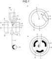
- FIG. 1 is a schematic cross-sectional view illustrating an embodiment of a fiber manufacturing apparatus of the present invention.
- FIGS. 2 to 8 are schematic cross-sectional views of other embodiments of the fiber manufacturing apparatus of the present invention.
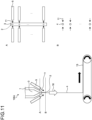
- FIGS. 9 to 11 are schematic cross-sectional views of embodiments of a conventional fiber manufacturing apparatus.
- the figures A and B illustrated on the right side of the drawing are cross-sectional views along lines A and B in the embodiment illustrated on the left side of the drawing.
- FIG. 1 are schematic views for accurately conveying the main points of the present invention, the drawings are simplified, a spinning device of the present invention is not particularly limited, and the dimensional ratio and the like can be changed according to the embodiment.
- a polymer 3 after being discharged from a discharge hole 2 in each drawing has a large size in order to illustrate a torsional force in an easily understandable manner.
- a stretching phenomenon of a fiber 4 in the fiber manufacturing method of the present invention will be described. Referring to FIG. 9 .
- a conventional fiber manufacturing method generally called melt-blowing
- an injection flow 11 is directly injected to one fiber 4 formed of the polymer 3 discharged from the discharge hole 2 by two nozzles disposed to face each other, and a stretching force 16 is applied to the fiber 4.
- the polymer 3 is discharged from the discharge hole 2 in a state where the viscosity is low, and the stretching force 16 is applied to stretch the fiber 4 in the polymer discharge direction.
- the molecular orientation of the polymer 3 in the fiber 4 is aligned in the longitudinal direction of the fiber.
- the molecular orientation in the fiber 4 is promoted, the polymer 3 is hardly deformed in the orientation direction, that is, hardly stretched. Therefore, in the conventional manufacturing method, there is a limit in reducing the diameter of the fiber 4.
- the present inventors have conducted intensive studies in order to solve the above problems, and as a result, have focused on the direction of the molecular orientation of the fiber 4.
- the stretching direction of the fiber 4 and the orientation of the molecular orientation are the same direction, it was considered that the inhibition of stretching due to the molecular orientation can be suppressed by making this direction different.
- FIG. 21 A relationship between the molecular orientation and stretching of the polymer 3 will be described with reference to FIG. 21 .
- Molecular chains 22 exist inside the polymer 3, and when the polymer 3 is discharged from the discharge hole 2 at the time of spinning, the polymer 3 is aligned in the longitudinal direction of the fiber 4 and extended by the stretching force 16 to be further aligned, and the molecular chains 22 are oriented as illustrated in figure (a). Since the molecular chains 22 in the polymer 3 are oriented, there is no room for the molecular chains 22 to be deformed in the orientation direction, and the stretching of the polymer 3 in the orientation direction is suppressed.
- the present inventors have considered that it is effective to disturb the orientation of the molecular chains 22 during stretching in order to prevent the suppression of stretching. It has been studied to disturb the orientation of the molecular chains 22 in the polymer 3 by applying a force to move the polymer 3 in a direction perpendicular to the longitudinal direction together with the stretching force 16 in the longitudinal direction at the time of stretching.
- a torsional force is continuously applied in a direction perpendicular to the longitudinal direction of the fiber 4, which is the stretching direction, and the fiber 4 is rotated at a high speed, whereby the molecular orientation in the longitudinal direction can be disturbed and the fiber 4 can be stretched.
- the fiber 4 revolves orbitally around the center of the swirling flow 12 with the discharge portion as a fixed point in addition to the rotation, so that the action of disturbing the molecular orientation in the longitudinal direction is promoted, and the fiber 4 can be more efficiently stretched.
- the fiber 4 is swirled at a high speed by the swirling flow 12 with a straight line extending from the discharge hole 2 in the polymer discharge direction as a central axis.
- This swirling motion causes a centrifugal force to act on the fiber 4 to promote stretching of the fiber 4, and the discharged fiber 4 swirls at a high speed, so that the fiber 4 can be reduced in diameter.
- the revolution speed of the fiber 4 is preferably 100 times/sec or more.
- the revolution speed thereof is more preferably 500 times/sec or more.
- the present inventors have found that the fiber 4 needs to rotate at a high speed in order to reduce the diameter of the fiber during the study.
- a conventional manufacturing method as illustrated in FIG. 9 only the stretching force 16 in the longitudinal direction is applied to the fiber 4, and a torsional force promoting the stretching cannot be applied to the fiber 4.
- the injection flow 11 is configured to be injected from an air-flow nozzle 5 installed at an angle so as to swirl, but since the injection flow 11 is injected into the atmosphere, the injection flow 11 cannot be diffused to form a swirling flow, and a torsional force that rotates the fiber 4 at a sufficient speed cannot be applied.
- the fiber 4 By stretching the fiber 4 by the manufacturing method of the present invention, the fiber 4 can be stretched while maintaining a state where the fiber 4 is easily deformed with respect to the stretching direction, and the diameter of the fiber 4 can be reduced.
- the present inventors have found that by applying the stretching force 16 acting in the longitudinal direction of the fiber 4 while rotating the fiber 4 about the center of the cross-section perpendicular to the longitudinal direction as an axis, the stretching efficiency to the fiber 4 is increased, and the diameter of the fiber 4 can be reduced.
- the rotation speed of the fiber 4 with respect to the discharge speed of the polymer 3 is important.
- the stretching phenomenon easily occurs in the vicinity of the discharge portion of the discharge hole 2.
- the rotation speed is slow with respect to the discharge speed, the number of rotations with respect to the length of the fiber 4 to be discharged is small, that is, the torsional force acting on the molecules in the fiber 4 becomes small, and the effect of disturbing the molecular arrangement by the torsional force cannot be sufficiently obtained, so that the effect of promoting stretching cannot be obtained.
- a discharge speed V (mm/sec) and a rotation speed W (times/sec) of the fiber 4 satisfy W/V ⁇ 0.1 (times/mm).
- a distance from the discharge hole 2 of a spinneret 1 in the discharge direction is preferably 100 mm or less, and more preferably 50 mm or less. Since the effect of the present invention can be obtained by rotating the fiber 4 in a section in which stretching is promoted, when the polymer 3 is a crystalline polymer in the fiber 4, W/V ⁇ 0.1 (times/mm) is preferably satisfied in at least one or more of sections in which the temperature is a melting point - 50°C or higher.
- FIG. 1 is an embodiment of a fiber manufacturing apparatus that generates a torsional force in the fiber 4 by a swirling flow.
- a fiber manufacturing apparatus 100 illustrated in FIG. 1 includes the spinneret 1 having the discharge hole 2 through which the polymer 3 as a raw material for the fiber 4 is discharged, an air nozzle 5 injecting the injection flow 11, the air nozzle being disposed around the polymer 3 discharged from the discharge hole 2, an air-flow closure member 6 disposed below the discharge hole 2 in a polymer discharge direction and having a space 7 through which the polymer 3 and the fiber 4 pass and a wall 8 surrounding the space 7, and a winding roller 14 winding up the fiber 4.
- the injection flow 11 is injected from the air nozzle 5 toward the wall 8 of the air-flow closure member 6 to form the swirling flow 12 in the space 7.
- the fiber 4 obtained by the polymer 3 discharged from the spinneret 1 is passed through the swirling flow 12, and then wound up by the winding roller 14.
- the air-flow closure member 6 includes the wall 8 having a cylindrical shape, and the space 7 surrounded by the wall 8 serves as an air flow passage.
- the space 7 is a through hole penetrating from one end surface to the other end surface of the air-flow closure member 6.
- the space 7 does not need to be surrounded by the wall 8 over the entire length, and may be surrounded by the wall 8 at a part of the entire length.
- FIG. 13 is a schematic view illustrating a form of forming a swirling flow in a space of the air-flow closure member in the fiber manufacturing apparatus of the present invention
- FIG. 17 is a schematic view for describing an injection direction of an injection flow from an air nozzle.
- the high-speed swirling flow 12 is formed by injecting the injection flow 11 having a velocity component in the circumferential direction of the fiber 4 toward the space 7 so as to collide with the wall 8 of the air-flow closure member 6 from the air nozzle 5.
- FIG. 13 is a schematic view illustrating a form of forming a swirling flow in a space of the air-flow closure member in the fiber manufacturing apparatus of the present invention
- FIG. 17 is a schematic view for describing an injection direction of an injection flow from an air nozzle.
- the high-speed swirling flow 12 is formed by injecting the injection flow 11 having a velocity component in the circumferential direction of the fiber 4 toward the space 7 so as to collide with the wall 8 of the air-flow closure member 6 from the
- a direction from a tip of the air nozzle 5 toward the center of the fiber 4 is taken as a radial direction, and a direction inclined by 90° from the radial direction is taken as a circumferential direction.
- the injection flow 11 having a velocity component in the circumferential direction of the fiber 4 is injected so as to collide with the wall 8 of the air-flow closure member 6 from the air nozzle 5.
- the swirling flow 12 is formed around the fiber 4.
- a torsional force 17 acts on the fiber 4, and the fiber 4 rotates at a high speed.
- the stretching force 16 acting in the longitudinal direction of the fiber 4 and the torsional force 17 acting in a direction perpendicular to the longitudinal direction of the fiber 4 are applied to the fiber 4, and the fiber 4 is stretched.
- This stretching method can promote reduction in the diameter of the fiber 4, so that the fiber 4 having a small diameter can be stably obtained.
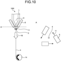
- FIG. 10 is a schematic cross-sectional view illustrating an embodiment of the conventional fiber manufacturing apparatus.
- the injection flow 11 expands and diffuses immediately after injection, so that it is difficult to form the swirling flow 12, and it is not possible to generate a torsional force causing the fiber 4 to rotate at a sufficient rotation speed.
- it is necessary to prevent diffusion of the injection flow 11.
- the fiber manufacturing apparatus 100 of the invention of the present application by installing the air-flow closure member 6, the diffusion of the injection flow 11 can be prevented and the diameter of the fiber 4 can be reduced.
- FIG. 16 is a schematic view for describing an installation angle of an air nozzle.
- an angle ⁇ is small with respect to the traveling direction of the fiber 4, a rotational velocity component of the swirling flow 12 tends to be weak.
- the angle ⁇ is larger than 90°, an air flow is injected in a direction opposite to the traveling direction of the fiber 4, so that an air flow is generated in a direction opposite to the stretching direction of the fiber 4, and the stretching of the fiber 4 is easily hindered. Therefore, the angle ⁇ between the air injection direction and the traveling direction of the fiber 4 is preferably 5 to 90°.
- FIG. 20 is a schematic view for describing an installation angle of an air nozzle in a cross-section perpendicular to the traveling direction of the fiber.
- the angle ⁇ formed by the straight line connecting the center of the discharge portion of the air nozzle 5 and the center of the fiber 4 with the injection direction of the air is preferably 5 to 90°.
- FIG. 2 is a schematic cross-sectional view illustrating another embodiment of the fiber manufacturing apparatus of the present invention.
- the injection flow 11 is supplied by one air nozzle 5, and the swirling flow 12 is formed inside the air-flow closure member 6.
- the injection flow 11 can be dispersed and supplied, and the swirling flow 12 can be formed more stably. Therefore, the injection flow is injected preferably by two or more air nozzles 5 and more preferably by three or more air nozzles 5.
- the swirling flow 12 with less disturbance can be formed by uniformly supplying the injection flow 11, and the fiber 4 can be continuously rotated. Therefore, when two or more air nozzles 5 are used, it is preferable that the air nozzles 5 are evenly disposed on a circle indicated by a dotted line in A of FIG. 2 , and the injection flow 11 is injected in the circumferential direction of the circle.
- the cross-sectional area of the air flow path of the air nozzle is preferably smaller than the cross-sectional area of the space 7.
- the cross-sectional shape of the air flow path of the air nozzle 5 is not limited to a circular shape and a rectangular shape, and may be any cross-sectional shape.
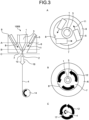
- FIG. 3 is a schematic cross-sectional view illustrating still another embodiment of the fiber manufacturing apparatus of the present invention.
- a horizontal cross-sectional area of the space of the air-flow closure member 6 is constant from an upper opening 9 to a lower opening 10.
- the space 7 preferably has a structure in which the cross-sectional area is reduced in the lower opening 10 than in the upper opening 9.
- the central axis of the spiral of the swirling flow at the lower opening 10 of the air-flow closure member 6 preferably coincides with the traveling direction of the fiber 4.
- the air-flow closure member 6 is a member forming the swirling flow 12 from the injection flow 11. As in the fiber manufacturing apparatus 100 illustrated in FIG. 1 , the swirling flow 12 formed by substantially half of the inner wall of the air-flow closure member 6 may collide with the fiber 4, or as in the fiber manufacturing apparatus 100B illustrated in FIG. 3 , the swirling flow 12 may collide with the fiber 4 only from the vicinity of the lower opening 10 of the air-flow closure member 6.
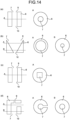
- FIG. 14 is a schematic view illustrating examples of the form of the air-flow closure member in the fiber manufacturing apparatus of the present invention.
- the air-flow closure member 6 can take various forms.
- the shape of the air-flow closure member 6 may be a shape in which the horizontal cross-sectional area of the space 7 is circular and constant as in (a), or may be a shape in which the horizontal cross-sectional area of the space 7 is circular and tapered as in (b).
- the shape of the air-flow closure member may be a shape in which the horizontal cross-sectional area of the space 7 is rectangular and constant as in (c), or may be a shape in which the horizontal cross-sectional area of the space 7 is circular and a passage is formed in the wall as in (d).
- the form of the air-flow closure member 6 may be a form other than (a) to (d).
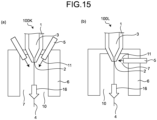
- FIG. 15 is a schematic cross-sectional view illustrating still another embodiment of the fiber manufacturing apparatus of the present invention.
- the winding roller 14 is not illustrated.
- the supply of the swirling flow 12 may become unstable due to the influence of a gas other than the injection flow 11 at the upper opening 9 of the air-flow closure member 6. Therefore, as in fiber manufacturing apparatuses 100K and 100L illustrated in FIG. 15 , the upper opening 9 of the air-flow closure member 6 may close portions other than an air injection port of the air nozzle 5.
- the cross-sectional area of the space 7 of the air-flow closure member 6 is preferably 1 mm 2 or more and 100 mm 2 or less in terms of the smallest cross-sectional area.
- FIG. 7 is a schematic cross-sectional view illustrating still another embodiment of the fiber manufacturing apparatus of the present invention.
- the spinneret 1 has a plurality of discharge holes 2, the polymer 3 is discharged from each of the plurality of discharge holes 2, and a plurality of fibers 4 thus discharged are stretched.
- the fiber manufacturing apparatus 100F includes one more air nozzles 5 than the number of the discharge holes 2, and the injection flow 11 is injected from the air nozzles 5 disposed in a zigzag manner to face each other with one discharge hole 2 interposed therebetween to form each of the swirling flows 12 around one fiber 4.
- the spinneret 1 having a plurality of discharge holes 2 with respect to one closure air-flow member 6 is used, and the injection flow 11 is injected from the plurality of air nozzles 5 so that the swirling flow 12 is generated in each fiber 4 to be discharged from each discharge hole 2.
- the production capacity of the fiber 4 having a small diameter can be improved.
- FIG. 5 is a schematic cross-sectional view illustrating still another embodiment of the fiber manufacturing apparatus of the present invention, in which the fiber is brought into direct contact with a rotating roller during rotating to apply a torsional force to the fiber.
- a fiber manufacturing apparatus 100D illustrated in FIG. 5 includes the spinneret 1 having the discharge hole 2 through which the polymer 3 is discharged, a rotating roller 13 disposed so as to be in contact with the fiber 4 obtained by stretching the polymer 3 discharged from the discharge hole 2, and the winding roller 14 winding up the fiber 4.
- the fiber 4 obtained by discharging the polymer 3 from the spinneret 1 is wound up by the winding roller 14 by rotating the rotating roller 13 to apply the torsional force 17 to the fiber 4 while the fiber 4 is in contact with the rotating roller 13.
- the fiber manufacturing apparatus 100D the fiber 4 is stretched in a state where the stretching force 16 acting on the fiber 4 in the longitudinal direction and the torsional force 17 acting in a direction perpendicular to the longitudinal direction are applied. This makes it possible to promote reduction in the diameter of the fiber 4, so that the fiber 4 having a small diameter can be stably obtained.
- the traveling fiber 4 may collide at the corner of the side surface of the rotating roller 13, and the fiber 4 may be cut in some cases. Therefore, the corner of the side surface portion of the rotating roller 13 is preferably a curved surface.
- the material for the side surface portion of the rotating roller 13 is preferably ceramics.
- the installation angle of the shaft of the rotating roller 13 is parallel to the traveling direction of the fiber 4 in FIG. 5 , but may be inclined within a range of 0 to 85 degrees from the direction parallel to the traveling direction of the fiber 4 as long as the torsional force 17 can be applied to the fiber 4.
- FIG. 8 is a schematic cross-sectional view illustrating still another embodiment of the fiber manufacturing apparatus of the present invention.
- a fiber manufacturing apparatus 100G illustrated in FIG. 8 has a configuration in which, in order to efficiently apply the torsional force 17 to the fiber 4, a plurality of spinnerets 1 are disposed around one rotating roller 13, and a plurality of fibers 4 discharged from each spinneret 1 are brought into contact with one rotating roller 13 to perform spinning by applying the torsional force.
- the production capacity of the fiber 4 having a small diameter can be improved.
- a method of collecting the fiber 4 is not limited to the winding roller 10 as illustrated in FIG. 1 , and the fiber 4 may be collected by using a conveyor 12 as illustrated in FIG. 7 , a fiber drum, or the like.
- the fiber 4 can travel without restricting the position of the fiber 4 at a collection position, so that the fiber 4 can be freely twisted without restricting the position of the fiber 4, and the effect of stretching can be enhanced.
- the present invention is an extremely versatile invention, and can be applied to manufacturing of all known fibers. Therefore, the polymer constituting the fiber is not particularly limited.
- the polymer constituting the fiber 4 include polyester, polyamide, polyphenylene sulfide, polyolefin, polyethylene, and polypropylene.
- Various functional particles such as a matting agent such as titanium dioxide, silicon oxide, kaolin, a coloring inhibitor, a stabilizer, an antioxidant, a deodorant, a flame retardant, a yarn friction-reducing agent, a coloring pigment, and a surface modifier, and additives such as an organic compound may be contained in the above-described polymer as long as the spinning stability and the like are not impaired, and copolymerization may be contained.
- the polymer constituting the fiber 4 may be composed of a single component or a plurality of components, and in the case of a plurality of components, for example, a core-sheath configuration, a side-by-side configuration, or the like can be mentioned.
- the cross-sectional shape of the fiber 4 forming the fiber 4 may be an irregular shape such as a circle, a triangle, a flat shape, a polygon, or a star shape, or may be hollow.
- the cross-sectional shape is different from a perfect circle, the surface area per volume is increased, so that it is easy to receive the torsional force 17 from the swirling flow 12 or the rotating roll 13, the rotation speed is increased, and the fiber 4 which is thinner can be obtained. Therefore, a cross-sectional shape flattened from a perfect circle is preferable, and a cross-sectional shape having irregularities on the surface is more preferable.
- An object of the present invention is to manufacture the fiber 4 having a small diameter, but the single yarn fineness is not particularly limited.
- FIG. 18 is a schematic view of a method of measuring a rotation speed of the fiber.
- One single yarn of 32 dtex measurement fibers 19 made of PET is fixed from the upper portion of the spinneret 1, and a high-speed camera 18 is installed.
- a black ink mark is added to the fiber surface at a position at a distance of 10 mm from the outlet surface of the discharge hole 2 of the spinneret 1, and the behavior of the fiber at the marked position is observed with the high-speed camera 18 for 0.1 seconds.
- the number of rotations per second of the fiber was measured by counting the number of rotations of the measurement fiber 19 from the movement of the point in the captured moving image, and employed as the rotation speed of the fiber.
- the number of rotations in the apparatuses of Examples and Comparative Examples described later was measured in a state where the measurement fiber 19 and the high-speed camera 18 were installed in the apparatus of each of Examples and Comparative Examples and the air nozzle 5 and the rotating roll 14 were operated.
- FIG. 19 is a schematic view of a method of measuring a pulling force.
- a tension meter 20 MODEL-RX-1 manufactured by Aikoh Engineering Co., Ltd.
- an air flow injected from the air nozzle 5 was brought into collision with the measurement fiber 19, and a tension (mN) generated at that time was manufactured by the tension meter 16.
- This measurement was repeated five times, and the average value (mN) thereof was taken as the stretching force.
- the stretching force in the apparatuses of Examples and Comparative Examples described later was measured in a state where the measurement fiber 19 was fixed to the apparatus of each of Examples and Comparative Examples, and the air nozzle 5 was operated.
- thermocouple A measurement portion of a thermocouple was disposed at a position where the distance in the discharge direction from the outlet surface of the spinneret discharge hole was 10 mm, and the ambient temperature of the spinneret discharge portion was measured at the time of spinning. This measurement was repeated three times, and the fiber discharge portion temperature (°C) was obtained.
- Fibers were manufactured using manufacturing apparatuses as illustrated in FIGS. 1 to 11 .
- a raw material resin a polypropylene resin having a melt flow rate at a weight of 2.16 Kg and a temperature of 230°C of 1100 g/10 min in accordance with ASTM-D1238, a density of 0.9 g/cm 3 , and a melting point of 180°C was used.
- a polymer having a molten resin temperature of 280°C was discharged from a discharge port of a spinneret at a nozzle hole diameter of 0.25 mm and a single hole discharge rate of 2 g/min, an injection flow was injected from an air nozzle at an air nozzle hole diameter for supplying hot air of 280°C of 2 mm and an angle formed by an air injection direction and a traveling direction of the fiber of 10° so that a stretching force was 15 mN, thereby manufacturing fibers under the conditions presented in Tables 1 to 3.
- the polymer discharge speed at this time is 755 mm/sec.
- the test results are presented in Tables 1 to 3.
- the influence of torsion in the swirling flow is evaluated.
- the polymer 3 was discharged from one discharge hole 2 of the spinneret 1 using the fiber manufacturing apparatus 100 illustrated in FIG. 1 .
- the air nozzle 5 was disposed at the angle ⁇ formed by the straight line connecting the air nozzle discharge portion and the center of the fiber with the injection direction of the injection flow of 80°.
- the injection flow was supplied from one air nozzle 5 to the space 7 of the air-flow closure member 6 having an inner diameter of ⁇ 5 mm and a height of 5 mm, the fiber 4 was stretched while applying a torsional force by the swirling flow 12 from a position immediately below the discharge hole 2, and the fiber was wound up by the winding roller 14.
- the fiber discharge portion temperature at the time of spinning was 215°C
- the number of rotations of the fiber W/the discharge speed V was 0.79 times/mm
- the average fiber diameter of the collected fibers was 2.60 ⁇ m.
- the temperature of the fibrous polymer is maximum at the discharge hole 2 during spinning and the temperature of the fibrous polymer decreases as the distance from the discharge hole 2 increases, when the temperature of the fibrous polymer and the rotation speed are measured at substantially the same position near the discharge hole, the temperature there of is (a melting point of the fibrous polymer - 50°C) or higher, and W/V is 0.1 times/mm or more at that position, it may be considered that the fibrous polymer rotates so as to satisfy W/V ⁇ 0.1 [times/mm] in one or more of sections in which the temperature of the fibrous polymer is (the melting point of the fibrous polymer - 50°C) or higher. The same may apply to the following Examples and Comparative Examples.
- the influence of the number of air nozzles is evaluated.
- the polymer 3 was discharged from one discharge hole 2 of the spinneret 1 using the fiber manufacturing apparatus 100A illustrated in FIG. 2 .
- the air nozzle 5 was disposed at the angle ⁇ formed by the straight line connecting the air nozzle discharge portion and the center of the fiber with the injection direction of the air of 80°.
- the injection flow was supplied from three air nozzles 5 to the space 7 of the air-flow closure member 6, the fiber 4 was stretched while applying a torsional force from a position immediately below the discharge hole 2, and the fiber 4 was wound up by the winding roller 14.
- the fiber discharge portion temperature at the time of spinning was 209°C
- the number of rotations of the fiber W/the discharge speed V was 0.83 times/mm
- the average fiber diameter of the collected fibers was 2.59 ⁇ m.
- the influence of the swirling flow generated by the air-flow closure members having different shapes is evaluated.
- the polymer 3 was discharged from one discharge hole 2 of the spinneret 1 using the fiber manufacturing apparatus 100B illustrated in FIG. 3 .
- the air nozzle 5 was disposed at the angle ⁇ formed by the straight line connecting the air nozzle discharge portion and the center of the fiber with the injection direction of the air of 80°.
- the injection flow was supplied from three air nozzles 5 to the space 7 of the air-flow closure member 6 (inner diameter: ⁇ 5 mm, height: 5 mm, taper angle: 60°, distance between air discharge portion surface and polymer discharge surface: 5 mm), the fiber 4 was stretched while applying a torsional force from a position immediately below the outlet of the discharge hole 2, and the fiber 4 was wound up by the winding roller 14.
- the fiber discharge portion temperature at the time of spinning was 195°C
- the number of rotations of the fiber W/the discharge speed V was 0.92 times/mm
- the average fiber diameter of the collected fibers was 2.56 ⁇ m.
- the influence of a decrease in temperature is evaluated in torsion in the swirling flow.
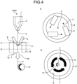
- the polymer 3 was discharged from one discharge hole 2 of the spinneret 1 using a fiber manufacturing apparatus 100C illustrated in FIG. 4 .
- the air nozzle was disposed at the angle ⁇ formed by the straight line connecting the air nozzle discharge portion and the center of the fiber with the injection direction of the air of 80°.
- the injection flow was supplied from three air nozzles to the space 7 of the air-flow closure member 6, the fiber 4 was stretched while applying a torsional force from a position at a distance of 200 mm from the outlet of the discharge hole 2, and the fiber 4 was wound up by the winding roller 14.
- the fiber discharge portion temperature at the time of spinning was 124°C, the number of rotations of the fiber W/the discharge speed V was 0.75 times/mm, and the average fiber diameter of the collected fibers was 3.16 ⁇ m.
- the influence of torsion by the rotating roller is evaluated.
- the polymer 3 was discharged from one discharge hole 2 of the spinneret 1 using the fiber manufacturing apparatus 100D illustrated in FIG. 5 .
- the fiber 4 was brought into contact with the rotating roller 13 during rotating (number of revolutions: 30 rpm) installed at a position at a distance of 200 mm from the outlet of the discharge hole 2 to apply a torsional force to the fibers 4, and the fibers 4 were wound up by the winding roller 14.
- the fiber discharge portion temperature at the time of spinning was 120°C
- the number of rotations of the fiber W/the discharge speed V was 0.22 times/mm
- the average fiber diameter of the collected fibers was 3.37 ⁇ m.
- the influence of changing the collection of fibers to a conveyor is evaluated.
- the polymer 3 was discharged from one discharge hole 2 of the spinneret 1 using a fiber manufacturing apparatus 100E illustrated in FIG. 6 .
- the air nozzle was disposed at the angle ⁇ formed by the straight line connecting the air nozzle discharge portion and the center of the fiber with the injection direction of the air of 80°.
- the injection flow was supplied from three air nozzles 5 to the space 7 of the air-flow closure member 6, the fiber 4 was stretched while applying a torsional force from a position immediately below the outlet of the discharge hole 2, and the fiber 4 was collected by a conveyor 15.
- the fiber discharge portion temperature at the time of spinning was 209°C, the number of rotations of the fiber W/the discharge speed V was 0.87 times/mm, and the average fiber diameter of the collected fibers was 2.58 ⁇ m.
- the influence when the number of discharge holes of the spinneret is increased is evaluated.
- the polymer 3 was discharged from ten discharge holes 2 of the spinneret 1 using the fiber manufacturing apparatus 100F illustrated in FIG. 7 .
- Eleven air nozzles were disposed in a zigzag manner to face each other with one discharge hole 2 interposed therebetween at the angle ⁇ formed by the straight line connecting the air nozzle discharge portion and the center of the fiber with the injection direction of the air of 80°.
- the injection flow was supplied from the air nozzle 5 to the space of the air-flow closure member 7, each of the swirling flows 12 was formed around one polymer, the fiber 4 was stretched while applying a torsional force from a position immediately below the outlet of the discharge hole 2, and the fiber 4 was collected by a conveyor 15.
- the fiber discharge portion temperature at the time of spinning was 190°C
- the number of rotations of the fiber W/the discharge speed V was 0.59 times/mm
- the average fiber diameter of the collected fibers was 2.66 ⁇ m.
- the influence when the number of discharge holes with respect to a rotating roller is increased is evaluated.
- the polymer 3 was discharged from each discharge hole 2 of ten spinnerets 1 using the fiber manufacturing apparatus 100G illustrated in FIG. 8 .
- Ten fibers 4 were brought into contact with the rotating roller 13 installed at a position at a distance of 200 mm from the outlet of the discharge hole 2 to apply a torsional force to the fibers 4, and the fibers 4 were wound up by the winding roller 14.
- the fiber discharge portion temperature at the time of spinning was 120°C
- the number of rotations of the fiber W/the discharge speed V was 0.20 times/mm
- the average fiber diameter of the collected fibers was 3.40 ⁇ m.
- a conventional spinning method of injecting an air flow without a swirling component is evaluated.
- the polymer 3 was discharged from one discharge hole 2 of the spinneret 1 using a fiber manufacturing apparatus 100H illustrated in FIG. 9 .
- the air nozzle was disposed at the angle ⁇ formed by the straight line connecting the air nozzle discharge portion and the center of the fiber with the injection direction of the air of 0°.
- the fiber 4 was stretched by injecting the injection flow from two air nozzles 5 to the discharged polymer 3, and the fiber 4 was wound up by the winding roller 14.
- the fiber discharge portion temperature at the time of spinning was 184°C, the fiber did not rotate, and the average fiber diameter of the collected fibers was 4.77 ⁇ m.
- a conventional spinning method of injecting an injection flow in a circumferential direction of a fiber in the atmosphere is evaluated.
- the fiber manufacturing apparatus 100I as illustrated in FIG. 10 was used.
- the polymer 3 was discharged from one discharge hole 2 of the spinneret 1, and the air nozzle was disposed at the angle ⁇ formed by the straight line connecting the air nozzle discharge portion and the center of the fiber with the injection direction of the air of 80°.
- the fiber 4 was stretched by injecting the injection flow from three air nozzles 5 to the discharged polymer 3, and the fiber 4 was wound up by the winding roller 14.
- the fiber discharge portion temperature at the time of spinning was 175°C, the fiber did not rotate, and the average fiber diameter of the collected fibers was 4.65 ⁇ m.
- a conventional spinning method of injecting an air flow without a swirling component and arranging a plurality of discharge holes is evaluated.
- a fiber manufacturing apparatus 100J illustrated in FIG. 11 was used, the polymer was discharged from each of ten discharge holes 2 of the spinneret 1, and twenty air nozzles 5 were disposed to face each other with one discharge hole 2 interposed therebetween at the angle ⁇ formed by the straight line connecting the air nozzle discharge portion and the center of the fiber with the injection direction of the air of 0°.
- the fiber 4 was stretched by injecting the injection flow from two air nozzles facing each other to the polymer 3 discharged from each discharge hole 2, and was collected by the conveyor 15.
- the fiber discharge portion temperature at the time of spinning was 185°C, the fiber did not rotate, and the average fiber diameter of the collected fibers was 4.95 ⁇ m.
- the influence of the number of rotations of the fiber is evaluated by reducing the angle ⁇ formed by the straight line connecting the air nozzle discharge portion and the center of the fiber with the injection direction of the air to suppress the swirling flow of the injection air.
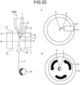
- a fiber manufacturing apparatus 100M illustrated in FIG. 22 was used, the polymer 3 was discharged from one discharge hole 2 of the spinneret 1, and the air nozzle was disposed at the angle ⁇ formed by the straight line connecting the air nozzle discharge portion and the center of the fiber with the injection direction of the air of 3°.
- the injection flow was supplied from one air nozzle 5 to the space 7 of the air-flow closure member 6, the fiber 4 was stretched while applying a torsional force from a position immediately below the outlet of the discharge hole, and the fiber 4 was wound up by the winding roller 14.
- the number of rotations of the fiber W/the discharge speed V was less than 0.1 times/mm.
- the fiber discharge portion temperature at the time of spinning was 210°C, the number of rotations of the fiber W/the discharge speed V was 0.05 times/mm, and the average fiber diameter of the collected fibers was 4.58 ⁇ m.
- the fiber manufacturing apparatus 100D illustrated in FIG. 5 was used, the polymer 3 was discharged from one discharge hole 2 of the spinneret 1, the fiber 4 was brought into contact with the rotating roller 13 (number of revolutions: 5 rpm) installed at a position at a distance of 200 mm from the outlet of the discharge hole to apply a torsional force to the fiber 4, and the fiber 4 was wound up by the winding roller 13.
- the number of rotations of the fiber W/the discharge speed V was less than 0.1 times/mm.
- the fiber discharge portion temperature at the time of spinning was 120°C, the number of rotations of the fiber W/the discharge speed V was 0.03 times/mm, and the average fiber diameter of the collected fibers was 4.67 ⁇ m.
- Example 1 The evaluation conditions and evaluation results of each Example and each Comparative Example are summarized in Tables 1 to 3.
- Example 1 the fiber was twisted by the swirling flow, and in Examples 5 and 8, the fiber was twisted by the rotating roller, so that the diameter reduction was promoted as compared with Comparative Examples 1 to 5.
- Example 1 since the temperature at a torsion portion was high, the diameter reduction was promoted as compared with Example 4.
- Example 1 Example 2
- Example 3 Example 4
- 80 80 80 80
- Presence or absence of air-flow closure member Present Present Present Present Present Present Present Present Present Present Present Present Present Present Present Present Present Present Present Present Present Present Present Present Present Present Present Present Present Present Present Present Present Present Present Present Present Present Present Present Present Present Present Present Present Present Present Present Present Present Present Present Present Present Present Present Present Present Present Present Present Present Present Present Present Present Present Present Present Present Present Present Present Present Present Present Present Present Present Present Present Present Present Present Present Present Present Present Present Present Present Present Present Present Present Present Present Present Present Present Present Present Present Present Present Present Present Present Present Present Present Present Present Present Present Present Present Present Present Present Present Present Present Present Present Present Present Present Present Present Present Present Present Present Present Present Present Present Present Present Present Present Present Present Present Present Present Present Present Present Present Present Present Present Present Present Present Present Present Present Present Present Present Present Present Present Present Present Present Present Present Present Present Present Present Present Present Present Present Present Present Present Present Present Present Present Present Present Present Present Present Present
- the manufacturing method and the manufacturing apparatus of the present invention are not limited to the filament, and can also be applied to spinning of fibers for other use applications such as a nonwoven fabric.
Landscapes
- Engineering & Computer Science (AREA)
- Mechanical Engineering (AREA)
- Textile Engineering (AREA)
- Spinning Methods And Devices For Manufacturing Artificial Fibers (AREA)
Abstract
Description
- The present invention relates to a method and apparatus suitable for manufacturing of fibers.
- In recent years, fiber diameter reduction (fineness reduction) has been required in many fields, and various research and development have been made on a method of discharging a thermoplastic polymer into a fibrous form from a spinneret and stretching the thermoplastic polymer, which is carried out in several stretching apparatuses. As a general stretching method, there are a method in which a speed difference is generated in a fiber by rotating a roller in a state where the fiber is in contact with the discharged fiber, a method in which a high-speed air flow is injected to a traveling fiber to apply tension to the fiber by a frictional force generated between the fiber and the air flow, and the like.
- Among them,
Patent Literature 1 discloses a method of stretching a traveling yarn.Patent Literature 1 discloses a method in which a gas jet is injected from three or more nozzles disposed around an outlet of a discharge hole to a fiber formed by discharging a fluid surrounding a periphery of a difficult substance to make into a fiber with an easy substance to make into a fiber from a spinneret to form a swirling flow around the fiber, and the gas jet is injected to the fiber to stretch the fiber. As a result, the discharged fiber is stretched by being swirled, and the difficult substance to make into a fiber can be made into a fiber. - As another method of stretching in a swirling flow,
Patent Literature 2 discloses a method in which compressed air is supplied to the inside of a duct having a spiral uneven portion on the inner wall and a cross-sectional area decreasing downstream, and traveling fibers pass through the duct to stretch the fibers. In this method, a stretching force is applied to the fiber by a flow velocity difference in a traveling direction of the fiber in the duct, and the fiber is twisted by a flow of spiral air, so that the fiber can be reduced in diameter. - As another method of stretching a traveling yarn, in
Patent Literature 3, a tubular fiber spinning needle includes an inlet through which a polymer solution is introduced, and an outlet which is an unfixed distal end and through which the polymer solution is discharged, the polymer is discharged from the outlet in a state where the outlet side is vibrated or rotated by injection of a compressed gas jet at the inlet to generate a stretching force acting on the polymer solution, the polymer solution at the outlet is divided into droplets, and the droplets are stretched by the compressed gas jet, whereby fibers can be obtained at a high polymer injection speed. -
- Patent Literature 1:
JP S60-119212 A - Patent Literature 2:
JP 2002-266154 A - Patent Literature 3:
JP 2022-32977 A - In the fiber manufacturing method disclosed in
Patent Literature 1, a configuration in which a gas jet is supplied by a plurality of inclined nozzles to form a swirling flow in the vicinity of a discharge portion is illustrated, but in the nozzle configuration ofPatent Literature 1, since a linear air flow formed by compressed gas is directly injected into an open space, the gas expands before forming the swirling flow, and the speed of the air flow decreases before colliding with the fiber, and thus the swirling speed of the fiber cannot be increased. Therefore, the swirling speed of the fiber decreases, and the effect of reducing the diameter of the fiber may not be sufficiently obtained in some cases. - In the fiber manufacturing method disclosed in
Patent Literature 2, a spiral air flow is formed in the duct, and the fiber is stretched while being twisted by the spiral air flow. However, in this method, the spiral air flow is formed on the wall surface of the duct, but the spiral air flow is less likely to be developed in the central portion, and the linear air flow is developed in the longitudinal direction of the duct. Therefore, it is difficult to apply a rotational force due to the spiral air flow to the fiber, and the effect of stretching by twisting the fiber cannot be obtained, and the fiber cannot be reduced in diameter in some cases. In particular, even when the post-discharge duct is disposed at a position away from the discharge hole of the spinneret, the fiber cannot be sufficiently stretched in some cases because the fiber is already cooled and solidified in the duct. - In the fiber manufacturing method disclosed in
Patent Literature 3, a polymer solution is discharged to stretch a yarn while a fiber spinning needle is vibrated or rotated. In this method, since a force is applied to the polymer from the wall surface of the outlet, a force for twisting the discharged polymer cannot be directly applied from the compressed gas jet, so that the effect of stretching by twisting the fiber may not be obtained in some cases. Since the space between the compressed gas jet injection position and the outlet through which the polymer is discharged is not sealed, the compressed gas jet is decelerated near the outlet, and the fiber cannot be sufficiently stretched in some cases. - Therefore, an object of the present invention is to provide a fiber manufacturing method and a fiber manufacturing apparatus capable of obtaining a fiber having a very small diameter by stretching a fibrous polymer discharged from a discharge hole while twisting the polymer at a high speed in a state where the polymer before solidification is easily deformed.
- A fiber manufacturing method according to the present invention to solve the above-described problem is a fiber manufacturing method of stretching a fibrous polymer discharged from a spinneret having a discharge hole to manufacture a fiber, the fiber manufacturing method including: applying a torsional force for rotating the fibrous polymer about a center of a cross-section perpendicular to a polymer discharge direction as an axis so as to satisfy the following formula to stretch the fibrous polymer while rotating the fibrous polymer, to the fibrous polymer discharged from the spinneret:

- V: discharge speed [mm/sec] of fibrous polymer
- W: rotation speed [times/sec] of fibrous polymer.
- It is preferable that the fiber manufacturing method according to the present invention includes any one or more of the features of the following (1) to (4).
- (1) The fibrous polymer is rotated so as to satisfy the following formula in one or more of sections in which a temperature of the fibrous polymer discharged from the spinneret is (a melting point of the fibrous polymer - 50°C) or higher:

- V: discharge speed [mm/sec] of fibrous polymer
- W: rotation speed [times/sec] of fibrous polymer.
- (2) The fibrous polymer is exposed to a swirling flow swirling in a rotation direction of the fibrous polymer to apply the torsional force in the rotation direction.
- (3) Each of the fibrous polymers is stretched while being swirled so as to revolve around a straight line extending from the discharge hole in the polymer discharge direction as a central axis.
- (4) A roller rotating in a direction opposite to a rotation direction of the fibrous polymer is brought into contact with the fibrous polymer to apply the torsional force in the rotation direction.
- A fiber manufacturing apparatus according to the present invention to solve the above-described problem is a fiber manufacturing apparatus of stretching a fibrous polymer to manufacture a fiber, the fiber manufacturing apparatus including: a spinneret having a discharge hole through which the fibrous polymer is discharged; an air-flow nozzle for injecting an air flow, the air-flow nozzle being disposed around the fibrous polymer discharged from the discharge hole; and an air-flow closure member disposed below the discharge hole in a polymer discharge direction and having a space through which the fibrous polymer passes and a wall surrounding the space, wherein a swirling flow is formed by an injection flow injected from the air-flow nozzle into the space to apply a torsional force in a rotation direction to the fibrous polymer so that the fibrous polymer rotates about a center of a cross-section perpendicular to the polymer discharge direction as an axis.
- In the fiber manufacturing apparatus according to the present invention, it is preferable that a swirling flow is formed by an injection flow injected from the air-flow nozzle into the space to allow the fibrous polymer to revolve around a straight line extending from the discharge hole in the polymer discharge direction as a central axis.
- A fiber manufacturing apparatus according to another aspect of the present invention to solve the above-described problem is a fiber manufacturing apparatus of stretching a fibrous polymer to manufacture a fiber, the fiber manufacturing apparatus including: a spinneret having a discharge hole through which the fibrous polymer is discharged; and a rotating roller disposed so as to be in contact with the fibrous polymer discharged from the discharge hole, wherein the rotating roller is rotated to apply a torsional force in a rotation direction to the fibrous polymer so that the fibrous polymer rotates about a center of a cross-section perpendicular to a discharge direction as an axis.
- In the present invention, the "polymer discharge direction" refers to a direction in which a fibrous polymer is discharged from a discharge hole.
- In the present invention, the "torsional force" refers to a force that acts on the fiber surface so as to generate a moment in the rotation direction around the center of the fiber cross-section in a plane perpendicular to the longitudinal direction of the fiber as an axis.
- In the present invention, the "discharge speed of the polymer" is a length at which the polymer is discharged from the discharge hole in the discharge direction of the polymer per unit time, and refers to a value calculated by dividing a volume of the polymer discharged from the discharge hole per unit time by a cross-sectional area of the discharge hole.
- In the present invention, the "rotation speed" refers to the number of revolutions at which the fiber rotates about the center of the fiber cross-section at 360 degrees per unit time in a plane perpendicular to the longitudinal direction of the fiber as an axis.
- In the present invention, the "swirling air flow" refers to an air flow having a flow that continuously rotates in a circumferential direction about one point on a plane perpendicular to the longitudinal direction of the fiber.
- According to the present invention, it is possible to manufacture a fiber having a very small diameter by stretching a fibrous polymer discharged from a discharge hole while twisting the polymer at a high speed in a state where the polymer before solidification is easily deformed.
-
-
FIG. 1 is a schematic cross-sectional view illustrating an embodiment of a fiber manufacturing apparatus of the present invention. -
FIG. 2 is a schematic cross-sectional view illustrating another embodiment of the fiber manufacturing apparatus of the present invention. -
FIG. 3 is a schematic cross-sectional view illustrating still another embodiment of the fiber manufacturing apparatus of the present invention. -
FIG. 4 is a schematic cross-sectional view illustrating still another embodiment of the fiber manufacturing apparatus of the present invention. -
FIG. 5 is a schematic cross-sectional view illustrating still another embodiment of the fiber manufacturing apparatus of the present invention. -
FIG. 6 is a schematic cross-sectional view illustrating still another embodiment of the fiber manufacturing apparatus of the present invention. -
FIG. 7 is a schematic cross-sectional view illustrating still another embodiment of the fiber manufacturing apparatus of the present invention. -
FIG. 8 is a schematic cross-sectional view illustrating still another embodiment of the fiber manufacturing apparatus of the present invention. -
FIG. 9 is a schematic cross-sectional view illustrating an embodiment of a conventional fiber manufacturing apparatus. -
FIG. 10 is a schematic cross-sectional view illustrating an embodiment of the conventional fiber manufacturing apparatus. -
FIG. 11 is a schematic cross-sectional view illustrating an embodiment of the conventional fiber manufacturing apparatus. -
FIG. 12 is a schematic view illustrating a form of an air-flow closure member in the fiber manufacturing apparatus of the present invention. -
FIG. 13 is a schematic view illustrating a form of forming a swirling flow in a space of the air-flow closure member in the fiber manufacturing apparatus of the present invention. -
FIG. 14 is a schematic view illustrating examples of the form of the air-flow closure member in the fiber manufacturing apparatus of the present invention. -
FIG. 15 is a schematic cross-sectional view illustrating still another embodiment of the fiber manufacturing apparatus of the present invention. -
FIG. 16 is a schematic view for describing an installation angle of an air nozzle. -
FIG. 17 is a schematic view for describing an injection direction of an injection flow from an air nozzle. -
FIG. 18 is a schematic cross-sectional view for describing a method of measuring a rotation speed of one fibrous polymer. -
FIG. 19 is a schematic cross-sectional view for describing a method of measuring a stretching force of one fibrous polymer. -
FIG. 20 is a schematic view for describing an installation angle of an air nozzle. -
FIG. 21 is a schematic view of a molecular arrangement in a discharge portion. -
FIG. 22 is a schematic cross-sectional view illustrating an embodiment of the conventional fiber manufacturing apparatus. - Hereinafter, various embodiments of a fiber manufacturing apparatus of the present invention and a fiber manufacturing method using the manufacturing apparatus will be described in detail with reference to the drawings.
FIG. 1 is a schematic cross-sectional view illustrating an embodiment of a fiber manufacturing apparatus of the present invention.FIGS. 2 to 8 are schematic cross-sectional views of other embodiments of the fiber manufacturing apparatus of the present invention.FIGS. 9 to 11 are schematic cross-sectional views of embodiments of a conventional fiber manufacturing apparatus. In each drawing, the figures A and B illustrated on the right side of the drawing are cross-sectional views along lines A and B in the embodiment illustrated on the left side of the drawing. These drawings are schematic views for accurately conveying the main points of the present invention, the drawings are simplified, a spinning device of the present invention is not particularly limited, and the dimensional ratio and the like can be changed according to the embodiment. Apolymer 3 after being discharged from adischarge hole 2 in each drawing has a large size in order to illustrate a torsional force in an easily understandable manner. - First, a stretching phenomenon of a
fiber 4 in the fiber manufacturing method of the present invention will be described. Referring toFIG. 9 . In a conventional fiber manufacturing method generally called melt-blowing, aninjection flow 11 is directly injected to onefiber 4 formed of thepolymer 3 discharged from thedischarge hole 2 by two nozzles disposed to face each other, and a stretchingforce 16 is applied to thefiber 4. Thepolymer 3 is discharged from thedischarge hole 2 in a state where the viscosity is low, and the stretchingforce 16 is applied to stretch thefiber 4 in the polymer discharge direction. At this time, the molecular orientation of thepolymer 3 in thefiber 4 is aligned in the longitudinal direction of the fiber. On the other hand, since the molecular orientation in thefiber 4 is promoted, thepolymer 3 is hardly deformed in the orientation direction, that is, hardly stretched. Therefore, in the conventional manufacturing method, there is a limit in reducing the diameter of thefiber 4. - The present inventors have conducted intensive studies in order to solve the above problems, and as a result, have focused on the direction of the molecular orientation of the
fiber 4. As described above, in the conventional stretching method, since the stretching direction of thefiber 4 and the orientation of the molecular orientation are the same direction, it was considered that the inhibition of stretching due to the molecular orientation can be suppressed by making this direction different. - A relationship between the molecular orientation and stretching of the
polymer 3 will be described with reference toFIG. 21 .Molecular chains 22 exist inside thepolymer 3, and when thepolymer 3 is discharged from thedischarge hole 2 at the time of spinning, thepolymer 3 is aligned in the longitudinal direction of thefiber 4 and extended by the stretchingforce 16 to be further aligned, and themolecular chains 22 are oriented as illustrated in figure (a). Since themolecular chains 22 in thepolymer 3 are oriented, there is no room for themolecular chains 22 to be deformed in the orientation direction, and the stretching of thepolymer 3 in the orientation direction is suppressed. That is, in the conventional stretching method, since thepolymer 3 is stretched by applying the stretchingforce 16 only in the longitudinal direction, further stretching in the longitudinal direction is suppressed after themolecular chains 22 are oriented in the longitudinal direction by stretching thepolymer 3. Therefore, the present inventors have considered that it is effective to disturb the orientation of themolecular chains 22 during stretching in order to prevent the suppression of stretching. It has been studied to disturb the orientation of themolecular chains 22 in thepolymer 3 by applying a force to move thepolymer 3 in a direction perpendicular to the longitudinal direction together with the stretchingforce 16 in the longitudinal direction at the time of stretching. As a means therefor, attention has been paid to a method in which a torsional force is applied in a direction in which thefiber 4 rotates about the center of a cross-section perpendicular to the discharge direction as an axis, that is, spins. When thefiber 4 rotates, thepolymer 3 moves in the cross-section of thefiber 4, and the orientation of themolecular chains 22 is disturbed as illustrated in figure (b). In particular, since themolecular chains 22 are likely to move when thepolymer 3 is in a molten state, the effect of disturbing themolecular chains 22 can be further obtained by rotating thefiber 4. - As described above, in a discharge portion of the
polymer 3 in which the molecules in thepolymer 3 are oriented and a stretching portion of thefiber 4, a torsional force is continuously applied in a direction perpendicular to the longitudinal direction of thefiber 4, which is the stretching direction, and thefiber 4 is rotated at a high speed, whereby the molecular orientation in the longitudinal direction can be disturbed and thefiber 4 can be stretched. - In the method in which the torsional force is applied to the
fiber 4 by a swirlingflow 12 as illustrated inFIG. 1 , thefiber 4 revolves orbitally around the center of the swirlingflow 12 with the discharge portion as a fixed point in addition to the rotation, so that the action of disturbing the molecular orientation in the longitudinal direction is promoted, and thefiber 4 can be more efficiently stretched. In the configuration in which the torsional force is applied by the swirlingflow 12, thefiber 4 is swirled at a high speed by the swirlingflow 12 with a straight line extending from thedischarge hole 2 in the polymer discharge direction as a central axis. This swirling motion causes a centrifugal force to act on thefiber 4 to promote stretching of thefiber 4, and the dischargedfiber 4 swirls at a high speed, so that thefiber 4 can be reduced in diameter. The revolution speed of thefiber 4 is preferably 100 times/sec or more. The revolution speed thereof is more preferably 500 times/sec or more. - Under such circumstances, the present inventors have found that the
fiber 4 needs to rotate at a high speed in order to reduce the diameter of the fiber during the study. In a conventional manufacturing method as illustrated inFIG. 9 , only the stretchingforce 16 in the longitudinal direction is applied to thefiber 4, and a torsional force promoting the stretching cannot be applied to thefiber 4. In a conventional manufacturing method as illustrated inFIG. 10 , theinjection flow 11 is configured to be injected from an air-flow nozzle 5 installed at an angle so as to swirl, but since theinjection flow 11 is injected into the atmosphere, theinjection flow 11 cannot be diffused to form a swirling flow, and a torsional force that rotates thefiber 4 at a sufficient speed cannot be applied. By stretching thefiber 4 by the manufacturing method of the present invention, thefiber 4 can be stretched while maintaining a state where thefiber 4 is easily deformed with respect to the stretching direction, and the diameter of thefiber 4 can be reduced. As described above, the present inventors have found that by applying the stretchingforce 16 acting in the longitudinal direction of thefiber 4 while rotating thefiber 4 about the center of the cross-section perpendicular to the longitudinal direction as an axis, the stretching efficiency to thefiber 4 is increased, and the diameter of thefiber 4 can be reduced. - In order to reduce the diameter of the
fiber 4, the rotation speed of thefiber 4 with respect to the discharge speed of thepolymer 3 is important. In the spinning of thefiber 4, the stretching phenomenon easily occurs in the vicinity of the discharge portion of thedischarge hole 2. When the rotation speed is slow with respect to the discharge speed, the number of rotations with respect to the length of thefiber 4 to be discharged is small, that is, the torsional force acting on the molecules in thefiber 4 becomes small, and the effect of disturbing the molecular arrangement by the torsional force cannot be sufficiently obtained, so that the effect of promoting stretching cannot be obtained. Therefore, it is necessary to rotate thefiber 4 so that a discharge speed V (mm/sec) and a rotation speed W (times/sec) of thefiber 4 satisfy W/V ≥ 0.1 (times/mm). Preferably, W/V ≥ 0.2 (times/mm). When the rotation speed is high with respect to the discharge linear speed, the number of rotations with respect to the length of thefiber 4 to be discharged is large, that is, the torsional force acting on thefiber 4 increases, and thefiber 4 may be broken by the shear stress generated in thefiber 4, so that it is preferable to adjust the discharge linear speed and the number of rotations to satisfy W/V ≤ 5000 (times/mm). - Since it is difficult to measure the rotation speed of the fiber during spinning, as the rotation speed in the present invention, a value obtained by measuring the rotation speed of the fiber at rest is used as described in "(1) Rotation speed (times/sec) of fiber" in Examples described later.
- The torsional force rotating the
fiber 4 is more easily affected by the torsional force in the vicinity of the discharge portion where the stretching phenomenon is actively generated, and the torsional stretching effect is easily obtained. Therefore, as the position where the torsional force is applied, a distance from thedischarge hole 2 of aspinneret 1 in the discharge direction is preferably 100 mm or less, and more preferably 50 mm or less. Since the effect of the present invention can be obtained by rotating thefiber 4 in a section in which stretching is promoted, when thepolymer 3 is a crystalline polymer in thefiber 4, W/V ≥ 0.1 (times/mm) is preferably satisfied in at least one or more of sections in which the temperature is a melting point - 50°C or higher. - Next, an apparatus configuration for realizing such a manufacturing method will be described. In order to rotate the
fiber 4, there are a method in which a torsional force is generated in thefiber 4 by a swirling flow and a method in which thefiber 4 is brought into direct contact with a rotating roller during rotating to apply the torsional force to thefiber 4. - The fiber manufacturing apparatus of the present invention will be described with reference to
FIG. 1. FIG. 1 is an embodiment of a fiber manufacturing apparatus that generates a torsional force in thefiber 4 by a swirling flow. Afiber manufacturing apparatus 100 illustrated inFIG. 1 includes thespinneret 1 having thedischarge hole 2 through which thepolymer 3 as a raw material for thefiber 4 is discharged, anair nozzle 5 injecting theinjection flow 11, the air nozzle being disposed around thepolymer 3 discharged from thedischarge hole 2, an air-flow closure member 6 disposed below thedischarge hole 2 in a polymer discharge direction and having aspace 7 through which thepolymer 3 and thefiber 4 pass and awall 8 surrounding thespace 7, and a windingroller 14 winding up thefiber 4. In this apparatus, theinjection flow 11 is injected from theair nozzle 5 toward thewall 8 of the air-flow closure member 6 to form the swirlingflow 12 in thespace 7. Thefiber 4 obtained by thepolymer 3 discharged from thespinneret 1 is passed through the swirlingflow 12, and then wound up by the windingroller 14. - A specific configuration of the air-
flow closure member 6 will be described with reference toFIG. 12 . The air-flow closure member 6 includes thewall 8 having a cylindrical shape, and thespace 7 surrounded by thewall 8 serves as an air flow passage. Thespace 7 is a through hole penetrating from one end surface to the other end surface of the air-flow closure member 6. Thespace 7 does not need to be surrounded by thewall 8 over the entire length, and may be surrounded by thewall 8 at a part of the entire length. - The flow of the air flow by the air-
flow closure member 6 will be described with reference toFIGS. 13 and17 .FIG. 13 is a schematic view illustrating a form of forming a swirling flow in a space of the air-flow closure member in the fiber manufacturing apparatus of the present invention, andFIG. 17 is a schematic view for describing an injection direction of an injection flow from an air nozzle. As illustrated inFIG. 13 , the high-speed swirling flow 12 is formed by injecting theinjection flow 11 having a velocity component in the circumferential direction of thefiber 4 toward thespace 7 so as to collide with thewall 8 of the air-flow closure member 6 from theair nozzle 5. As illustrated inFIG. 17 , for the injection direction of theinjection flow 11, a direction from a tip of theair nozzle 5 toward the center of thefiber 4 is taken as a radial direction, and a direction inclined by 90° from the radial direction is taken as a circumferential direction. - Referring again to
FIG. 1 . As illustrated in the cross-sectional view taken along line A, theinjection flow 11 having a velocity component in the circumferential direction of thefiber 4 is injected so as to collide with thewall 8 of the air-flow closure member 6 from theair nozzle 5. Then, as illustrated in the cross-sectional view taken along line B, the swirlingflow 12 is formed around thefiber 4. When thefiber 4 passes through the swirlingflow 12, atorsional force 17 acts on thefiber 4, and thefiber 4 rotates at a high speed. As a result, the stretchingforce 16 acting in the longitudinal direction of thefiber 4 and thetorsional force 17 acting in a direction perpendicular to the longitudinal direction of thefiber 4 are applied to thefiber 4, and thefiber 4 is stretched. This stretching method can promote reduction in the diameter of thefiber 4, so that thefiber 4 having a small diameter can be stably obtained. -
FIG. 10 is a schematic cross-sectional view illustrating an embodiment of the conventional fiber manufacturing apparatus. In a method of directly injecting theinjection flow 11 from theair nozzle 5 into an open space without thewall 8 in the periphery thereof as in a fiber manufacturing apparatus 100I illustrated inFIG. 10 , theinjection flow 11 expands and diffuses immediately after injection, so that it is difficult to form the swirlingflow 12, and it is not possible to generate a torsional force causing thefiber 4 to rotate at a sufficient rotation speed. In order to generate a swirling flow in which thefiber 4 rotates sufficiently, it is necessary to prevent diffusion of theinjection flow 11. In thefiber manufacturing apparatus 100 of the invention of the present application, by installing the air-flow closure member 6, the diffusion of theinjection flow 11 can be prevented and the diameter of thefiber 4 can be reduced. - An air injection angle of the
air nozzle 5 with respect to a traveling direction of thefiber 4 will be described with reference toFIG. 16. FIG. 16 is a schematic view for describing an installation angle of an air nozzle. When an angle α is small with respect to the traveling direction of thefiber 4, a rotational velocity component of the swirlingflow 12 tends to be weak. On the other hand, when the angle α is larger than 90°, an air flow is injected in a direction opposite to the traveling direction of thefiber 4, so that an air flow is generated in a direction opposite to the stretching direction of thefiber 4, and the stretching of thefiber 4 is easily hindered. Therefore, the angle α between the air injection direction and the traveling direction of thefiber 4 is preferably 5 to 90°. - An injection angle of the
injection flow 11 from theair nozzle 5 in a cross-section perpendicular to the traveling direction of thefiber 4 will be described with reference toFIG. 20. FIG. 20 is a schematic view for describing an installation angle of an air nozzle in a cross-section perpendicular to the traveling direction of the fiber. When an angle β formed by a straight line connecting the center of the discharge portion of theair nozzle 5 and the center of the fiber 4 (a shortest straight line connecting theair nozzle 5 and the fiber 4) with the injection direction of theinjection flow 11 is small, theinjection flow 11 directly collides with thefiber 4, and the swirlingflow 12 is likely to be hardly formed. On the other hand, when the angle β is large, the injection flow is injected in a direction opposite to the direction of thefiber 4, and energy loss is likely to occur. Therefore, the angle β formed by the straight line connecting the center of the discharge portion of theair nozzle 5 and the center of thefiber 4 with the injection direction of the air is preferably 5 to 90°. -
FIG. 2 is a schematic cross-sectional view illustrating another embodiment of the fiber manufacturing apparatus of the present invention. In thefiber manufacturing apparatus 100 ofFIG. 1 , theinjection flow 11 is supplied by oneair nozzle 5, and the swirlingflow 12 is formed inside the air-flow closure member 6. On the other hand, as in afiber manufacturing apparatus 100A illustrated inFIG. 2 , by installing a large number of theair nozzle 5, theinjection flow 11 can be dispersed and supplied, and the swirlingflow 12 can be formed more stably. Therefore, the injection flow is injected preferably by two ormore air nozzles 5 and more preferably by three ormore air nozzles 5. - In the case of using two or
more air nozzles 5, the swirlingflow 12 with less disturbance can be formed by uniformly supplying theinjection flow 11, and thefiber 4 can be continuously rotated. Therefore, when two ormore air nozzles 5 are used, it is preferable that theair nozzles 5 are evenly disposed on a circle indicated by a dotted line in A ofFIG. 2 , and theinjection flow 11 is injected in the circumferential direction of the circle. - In order to form the swirling
flow 12 in thespace 7 of the air-flow closure member 6, the cross-sectional area of the air flow path of the air nozzle is preferably smaller than the cross-sectional area of thespace 7. The cross-sectional shape of the air flow path of theair nozzle 5 is not limited to a circular shape and a rectangular shape, and may be any cross-sectional shape. -
FIG. 3 is a schematic cross-sectional view illustrating still another embodiment of the fiber manufacturing apparatus of the present invention. In thefiber manufacturing apparatus 100 ofFIG. 1 , a horizontal cross-sectional area of the space of the air-flow closure member 6 is constant from anupper opening 9 to alower opening 10. However, in order to take theinjection flow 11 from theair nozzle 5 into thespace 7 of the air-flow closure member 6, the larger the cross-sectional area of thespace 7 in theupper opening 9 of the air-flow closure member 6 is, the easier theinjection flow 11 is taken into, and the smaller the cross-sectional area of thespace 7 in thelower opening 10 is, the faster the air flow in the air-flow closure member 6 and the easier the swirlingflow 12 is accelerated. Therefore, as in afiber manufacturing apparatus 100B illustrated inFIG. 3 , thespace 7 preferably has a structure in which the cross-sectional area is reduced in thelower opening 10 than in theupper opening 9. - Since the
fiber 4 is rotated by the swirlingflow 12 formed by the air-flow closure member 6, the center of the swirlingflow 12 and the discharge direction of thefiber 4 coincide with each other, so that thefiber 4 can be efficiently rotated. Therefore, the central axis of the spiral of the swirling flow at thelower opening 10 of the air-flow closure member 6 preferably coincides with the traveling direction of thefiber 4. - The air-
flow closure member 6 is a member forming the swirlingflow 12 from theinjection flow 11. As in thefiber manufacturing apparatus 100 illustrated inFIG. 1 , the swirlingflow 12 formed by substantially half of the inner wall of the air-flow closure member 6 may collide with thefiber 4, or as in thefiber manufacturing apparatus 100B illustrated inFIG. 3 , the swirlingflow 12 may collide with thefiber 4 only from the vicinity of thelower opening 10 of the air-flow closure member 6. -
FIG. 14 is a schematic view illustrating examples of the form of the air-flow closure member in the fiber manufacturing apparatus of the present invention. As illustrated by way of examples inFIG. 14 , the air-flow closure member 6 can take various forms. The shape of the air-flow closure member 6 may be a shape in which the horizontal cross-sectional area of thespace 7 is circular and constant as in (a), or may be a shape in which the horizontal cross-sectional area of thespace 7 is circular and tapered as in (b). The shape of the air-flow closure member may be a shape in which the horizontal cross-sectional area of thespace 7 is rectangular and constant as in (c), or may be a shape in which the horizontal cross-sectional area of thespace 7 is circular and a passage is formed in the wall as in (d). The form of the air-flow closure member 6 may be a form other than (a) to (d). -
FIG. 15 is a schematic cross-sectional view illustrating still another embodiment of the fiber manufacturing apparatus of the present invention. InFIG. 15 , the windingroller 14 is not illustrated. In thefiber manufacturing apparatus 100 ofFIG. 1 , the supply of the swirlingflow 12 may become unstable due to the influence of a gas other than theinjection flow 11 at theupper opening 9 of the air-flow closure member 6. Therefore, as infiber manufacturing apparatuses FIG. 15 , theupper opening 9 of the air-flow closure member 6 may close portions other than an air injection port of theair nozzle 5. - When the cross-sectional area of the
space 7 of the air-flow closure member 6 is too small, thefiber 4 adheres to the wall surface of the air-flow closure member 6 at the time of causing thefiber 4 to pass, so that the spinnability is easily deteriorated. On the other hand, when the cross-sectional area is too large, the swirlingflow 12 is decelerated, and a torsional force for rotating thefiber 4 tends to be weak. Therefore, the cross-sectional area of thespace 7 is preferably 1 mm2 or more and 100 mm2 or less in terms of the smallest cross-sectional area. -
FIG. 7 is a schematic cross-sectional view illustrating still another embodiment of the fiber manufacturing apparatus of the present invention. In afiber manufacturing apparatus 100F ofFIG. 7 , thespinneret 1 has a plurality ofdischarge holes 2, thepolymer 3 is discharged from each of the plurality ofdischarge holes 2, and a plurality offibers 4 thus discharged are stretched. Thefiber manufacturing apparatus 100F includes onemore air nozzles 5 than the number of the discharge holes 2, and theinjection flow 11 is injected from theair nozzles 5 disposed in a zigzag manner to face each other with onedischarge hole 2 interposed therebetween to form each of the swirling flows 12 around onefiber 4. Thespinneret 1 having a plurality ofdischarge holes 2 with respect to one closure air-flow member 6 is used, and theinjection flow 11 is injected from the plurality ofair nozzles 5 so that the swirlingflow 12 is generated in eachfiber 4 to be discharged from eachdischarge hole 2. In thefiber manufacturing apparatus 100F, the production capacity of thefiber 4 having a small diameter can be improved. -
FIG. 5 is a schematic cross-sectional view illustrating still another embodiment of the fiber manufacturing apparatus of the present invention, in which the fiber is brought into direct contact with a rotating roller during rotating to apply a torsional force to the fiber. Afiber manufacturing apparatus 100D illustrated inFIG. 5 includes thespinneret 1 having thedischarge hole 2 through which thepolymer 3 is discharged, a rotatingroller 13 disposed so as to be in contact with thefiber 4 obtained by stretching thepolymer 3 discharged from thedischarge hole 2, and the windingroller 14 winding up thefiber 4. In this apparatus, thefiber 4 obtained by discharging thepolymer 3 from thespinneret 1 is wound up by the windingroller 14 by rotating therotating roller 13 to apply thetorsional force 17 to thefiber 4 while thefiber 4 is in contact with the rotatingroller 13. In thefiber manufacturing apparatus 100D, thefiber 4 is stretched in a state where the stretchingforce 16 acting on thefiber 4 in the longitudinal direction and thetorsional force 17 acting in a direction perpendicular to the longitudinal direction are applied. This makes it possible to promote reduction in the diameter of thefiber 4, so that thefiber 4 having a small diameter can be stably obtained. - In the
fiber manufacturing apparatus 100D, since the rotatingroller 13 rotates at a high speed, the travelingfiber 4 may collide at the corner of the side surface of therotating roller 13, and thefiber 4 may be cut in some cases. Therefore, the corner of the side surface portion of therotating roller 13 is preferably a curved surface. - Since the rotating
roller 13 comes into contact with the travelingfiber 4, the side surface portion of therotating roller 13 that comes into contact with thefiber 4 wears when continuously operated. Therefore, the material for the side surface portion of therotating roller 13 is preferably ceramics. - The installation angle of the shaft of the
rotating roller 13 is parallel to the traveling direction of thefiber 4 inFIG. 5 , but may be inclined within a range of 0 to 85 degrees from the direction parallel to the traveling direction of thefiber 4 as long as thetorsional force 17 can be applied to thefiber 4. -
FIG. 8 is a schematic cross-sectional view illustrating still another embodiment of the fiber manufacturing apparatus of the present invention. Afiber manufacturing apparatus 100G illustrated inFIG. 8 has a configuration in which, in order to efficiently apply thetorsional force 17 to thefiber 4, a plurality ofspinnerets 1 are disposed around one rotatingroller 13, and a plurality offibers 4 discharged from eachspinneret 1 are brought into contact with one rotatingroller 13 to perform spinning by applying the torsional force. In thefiber manufacturing apparatus 100G, the production capacity of thefiber 4 having a small diameter can be improved. - Next, a common preferred embodiment in the present invention will be described.
- Refer to
FIGS. 1 and7 . A method of collecting thefiber 4 is not limited to the windingroller 10 as illustrated inFIG. 1 , and thefiber 4 may be collected by using aconveyor 12 as illustrated inFIG. 7 , a fiber drum, or the like. By using theconveyor 12 or the fiber drum, thefiber 4 can travel without restricting the position of thefiber 4 at a collection position, so that thefiber 4 can be freely twisted without restricting the position of thefiber 4, and the effect of stretching can be enhanced. - The present invention is an extremely versatile invention, and can be applied to manufacturing of all known fibers. Therefore, the polymer constituting the fiber is not particularly limited. Examples of the polymer constituting the
fiber 4 include polyester, polyamide, polyphenylene sulfide, polyolefin, polyethylene, and polypropylene. Various functional particles such as a matting agent such as titanium dioxide, silicon oxide, kaolin, a coloring inhibitor, a stabilizer, an antioxidant, a deodorant, a flame retardant, a yarn friction-reducing agent, a coloring pigment, and a surface modifier, and additives such as an organic compound may be contained in the above-described polymer as long as the spinning stability and the like are not impaired, and copolymerization may be contained. - The polymer constituting the
fiber 4 may be composed of a single component or a plurality of components, and in the case of a plurality of components, for example, a core-sheath configuration, a side-by-side configuration, or the like can be mentioned. - The cross-sectional shape of the
fiber 4 forming thefiber 4 may be an irregular shape such as a circle, a triangle, a flat shape, a polygon, or a star shape, or may be hollow. At this time, since the cross-sectional shape is different from a perfect circle, the surface area per volume is increased, so that it is easy to receive thetorsional force 17 from the swirlingflow 12 or therotating roll 13, the rotation speed is increased, and thefiber 4 which is thinner can be obtained. Therefore, a cross-sectional shape flattened from a perfect circle is preferable, and a cross-sectional shape having irregularities on the surface is more preferable. - An object of the present invention is to manufacture the
fiber 4 having a small diameter, but the single yarn fineness is not particularly limited. - Hereinafter, the present invention will be described more specifically with reference to Examples. Method of measuring characteristic values, and the like in Examples are as follows.
-
FIG. 18 is a schematic view of a method of measuring a rotation speed of the fiber. One single yarn of 32dtex measurement fibers 19 made of PET is fixed from the upper portion of thespinneret 1, and a high-speed camera 18 is installed. A black ink mark is added to the fiber surface at a position at a distance of 10 mm from the outlet surface of thedischarge hole 2 of thespinneret 1, and the behavior of the fiber at the marked position is observed with the high-speed camera 18 for 0.1 seconds. The number of rotations per second of the fiber was measured by counting the number of rotations of themeasurement fiber 19 from the movement of the point in the captured moving image, and employed as the rotation speed of the fiber. The number of rotations in the apparatuses of Examples and Comparative Examples described later was measured in a state where themeasurement fiber 19 and the high-speed camera 18 were installed in the apparatus of each of Examples and Comparative Examples and theair nozzle 5 and therotating roll 14 were operated. - Ten samples were randomly collected from the spun fibers, and surface photographs were taken with a microscope at a magnification of 1000. The widths of the fibers were measured from the photographs of the samples, and the average value thereof was adopted as an average fiber diameter.
- From the polymer discharge amount (mm3/sec) discharged from the discharge hole of the spinneret set under each condition and the cross-sectional area (mm3) of the discharge hole at the outlet of the spinneret, the discharge speed was calculated based on the following formula.
· Discharge speed = Polymer discharge amount/discharge hole cross-sectional area -
FIG. 19 is a schematic view of a method of measuring a pulling force. First, one single yarn of 32dtex measurement fiber 19 made of PET was fixed to a tension meter 20 (MODEL-RX-1 manufactured by Aikoh Engineering Co., Ltd.) at a length of 1000 mm from the spinneret lower surface, an air flow injected from theair nozzle 5 was brought into collision with themeasurement fiber 19, and a tension (mN) generated at that time was manufactured by thetension meter 16. This measurement was repeated five times, and the average value (mN) thereof was taken as the stretching force. The stretching force in the apparatuses of Examples and Comparative Examples described later was measured in a state where themeasurement fiber 19 was fixed to the apparatus of each of Examples and Comparative Examples, and theair nozzle 5 was operated. - A measurement portion of a thermocouple was disposed at a position where the distance in the discharge direction from the outlet surface of the spinneret discharge hole was 10 mm, and the ambient temperature of the spinneret discharge portion was measured at the time of spinning. This measurement was repeated three times, and the fiber discharge portion temperature (°C) was obtained.
- Fibers were manufactured using manufacturing apparatuses as illustrated in
FIGS. 1 to 11 . As a raw material resin, a polypropylene resin having a melt flow rate at a weight of 2.16 Kg and a temperature of 230°C of 1100 g/10 min in accordance with ASTM-D1238, a density of 0.9 g/cm3, and a melting point of 180°C was used. A polymer having a molten resin temperature of 280°C was discharged from a discharge port of a spinneret at a nozzle hole diameter of 0.25 mm and a single hole discharge rate of 2 g/min, an injection flow was injected from an air nozzle at an air nozzle hole diameter for supplying hot air of 280°C of 2 mm and an angle formed by an air injection direction and a traveling direction of the fiber of 10° so that a stretching force was 15 mN, thereby manufacturing fibers under the conditions presented in Tables 1 to 3. The polymer discharge speed at this time is 755 mm/sec. The test results are presented in Tables 1 to 3. - The influence of torsion in the swirling flow is evaluated. The
polymer 3 was discharged from onedischarge hole 2 of thespinneret 1 using thefiber manufacturing apparatus 100 illustrated inFIG. 1 . Theair nozzle 5 was disposed at the angle β formed by the straight line connecting the air nozzle discharge portion and the center of the fiber with the injection direction of the injection flow of 80°. The injection flow was supplied from oneair nozzle 5 to thespace 7 of the air-flow closure member 6 having an inner diameter of Φ5 mm and a height of 5 mm, thefiber 4 was stretched while applying a torsional force by the swirlingflow 12 from a position immediately below thedischarge hole 2, and the fiber was wound up by the windingroller 14. The fiber discharge portion temperature at the time of spinning was 215°C, the number of rotations of the fiber W/the discharge speed V was 0.79 times/mm, and the average fiber diameter of the collected fibers was 2.60 µm. - Since the temperature of the fibrous polymer is maximum at the
discharge hole 2 during spinning and the temperature of the fibrous polymer decreases as the distance from thedischarge hole 2 increases, when the temperature of the fibrous polymer and the rotation speed are measured at substantially the same position near the discharge hole, the temperature there of is (a melting point of the fibrous polymer - 50°C) or higher, and W/V is 0.1 times/mm or more at that position, it may be considered that the fibrous polymer rotates so as to satisfy W/V ≥ 0.1 [times/mm] in one or more of sections in which the temperature of the fibrous polymer is (the melting point of the fibrous polymer - 50°C) or higher. The same may apply to the following Examples and Comparative Examples. - The influence of the number of air nozzles is evaluated. The
polymer 3 was discharged from onedischarge hole 2 of thespinneret 1 using thefiber manufacturing apparatus 100A illustrated inFIG. 2 . Theair nozzle 5 was disposed at the angle β formed by the straight line connecting the air nozzle discharge portion and the center of the fiber with the injection direction of the air of 80°. The injection flow was supplied from threeair nozzles 5 to thespace 7 of the air-flow closure member 6, thefiber 4 was stretched while applying a torsional force from a position immediately below thedischarge hole 2, and thefiber 4 was wound up by the windingroller 14. The fiber discharge portion temperature at the time of spinning was 209°C, the number of rotations of the fiber W/the discharge speed V was 0.83 times/mm, and the average fiber diameter of the collected fibers was 2.59 µm. - The influence of the swirling flow generated by the air-flow closure members having different shapes is evaluated. The
polymer 3 was discharged from onedischarge hole 2 of thespinneret 1 using thefiber manufacturing apparatus 100B illustrated inFIG. 3 . Theair nozzle 5 was disposed at the angle β formed by the straight line connecting the air nozzle discharge portion and the center of the fiber with the injection direction of the air of 80°. The injection flow was supplied from threeair nozzles 5 to thespace 7 of the air-flow closure member 6 (inner diameter: Φ5 mm, height: 5 mm, taper angle: 60°, distance between air discharge portion surface and polymer discharge surface: 5 mm), thefiber 4 was stretched while applying a torsional force from a position immediately below the outlet of thedischarge hole 2, and thefiber 4 was wound up by the windingroller 14. The fiber discharge portion temperature at the time of spinning was 195°C, the number of rotations of the fiber W/the discharge speed V was 0.92 times/mm, and the average fiber diameter of the collected fibers was 2.56 µm. - The influence of a decrease in temperature is evaluated in torsion in the swirling flow. The
polymer 3 was discharged from onedischarge hole 2 of thespinneret 1 using afiber manufacturing apparatus 100C illustrated inFIG. 4 . The air nozzle was disposed at the angle β formed by the straight line connecting the air nozzle discharge portion and the center of the fiber with the injection direction of the air of 80°. The injection flow was supplied from three air nozzles to thespace 7 of the air-flow closure member 6, thefiber 4 was stretched while applying a torsional force from a position at a distance of 200 mm from the outlet of thedischarge hole 2, and thefiber 4 was wound up by the windingroller 14. The fiber discharge portion temperature at the time of spinning was 124°C, the number of rotations of the fiber W/the discharge speed V was 0.75 times/mm, and the average fiber diameter of the collected fibers was 3.16 µm. - The influence of torsion by the rotating roller is evaluated. The
polymer 3 was discharged from onedischarge hole 2 of thespinneret 1 using thefiber manufacturing apparatus 100D illustrated inFIG. 5 . Thefiber 4 was brought into contact with the rotatingroller 13 during rotating (number of revolutions: 30 rpm) installed at a position at a distance of 200 mm from the outlet of thedischarge hole 2 to apply a torsional force to thefibers 4, and thefibers 4 were wound up by the windingroller 14. The fiber discharge portion temperature at the time of spinning was 120°C, the number of rotations of the fiber W/the discharge speed V was 0.22 times/mm, and the average fiber diameter of the collected fibers was 3.37 µm. - The influence of changing the collection of fibers to a conveyor is evaluated. The
polymer 3 was discharged from onedischarge hole 2 of thespinneret 1 using afiber manufacturing apparatus 100E illustrated inFIG. 6 . The air nozzle was disposed at the angle β formed by the straight line connecting the air nozzle discharge portion and the center of the fiber with the injection direction of the air of 80°. The injection flow was supplied from threeair nozzles 5 to thespace 7 of the air-flow closure member 6, thefiber 4 was stretched while applying a torsional force from a position immediately below the outlet of thedischarge hole 2, and thefiber 4 was collected by aconveyor 15. The fiber discharge portion temperature at the time of spinning was 209°C, the number of rotations of the fiber W/the discharge speed V was 0.87 times/mm, and the average fiber diameter of the collected fibers was 2.58 µm. - The influence when the number of discharge holes of the spinneret is increased is evaluated. The
polymer 3 was discharged from tendischarge holes 2 of thespinneret 1 using thefiber manufacturing apparatus 100F illustrated inFIG. 7 . Eleven air nozzles were disposed in a zigzag manner to face each other with onedischarge hole 2 interposed therebetween at the angle β formed by the straight line connecting the air nozzle discharge portion and the center of the fiber with the injection direction of the air of 80°. The injection flow was supplied from theair nozzle 5 to the space of the air-flow closure member 7, each of the swirling flows 12 was formed around one polymer, thefiber 4 was stretched while applying a torsional force from a position immediately below the outlet of thedischarge hole 2, and thefiber 4 was collected by aconveyor 15. The fiber discharge portion temperature at the time of spinning was 190°C, the number of rotations of the fiber W/the discharge speed V was 0.59 times/mm, and the average fiber diameter of the collected fibers was 2.66 µm. - The influence when the number of discharge holes with respect to a rotating roller is increased is evaluated. The
polymer 3 was discharged from eachdischarge hole 2 of tenspinnerets 1 using thefiber manufacturing apparatus 100G illustrated inFIG. 8 . Tenfibers 4 were brought into contact with the rotatingroller 13 installed at a position at a distance of 200 mm from the outlet of thedischarge hole 2 to apply a torsional force to thefibers 4, and thefibers 4 were wound up by the windingroller 14. The fiber discharge portion temperature at the time of spinning was 120°C, the number of rotations of the fiber W/the discharge speed V was 0.20 times/mm, and the average fiber diameter of the collected fibers was 3.40 µm. - A conventional spinning method of injecting an air flow without a swirling component is evaluated. The
polymer 3 was discharged from onedischarge hole 2 of thespinneret 1 using afiber manufacturing apparatus 100H illustrated inFIG. 9 . The air nozzle was disposed at the angle β formed by the straight line connecting the air nozzle discharge portion and the center of the fiber with the injection direction of the air of 0°. Thefiber 4 was stretched by injecting the injection flow from twoair nozzles 5 to the dischargedpolymer 3, and thefiber 4 was wound up by the windingroller 14. The fiber discharge portion temperature at the time of spinning was 184°C, the fiber did not rotate, and the average fiber diameter of the collected fibers was 4.77 µm. - A conventional spinning method of injecting an injection flow in a circumferential direction of a fiber in the atmosphere is evaluated. The fiber manufacturing apparatus 100I as illustrated in
FIG. 10 was used. Thepolymer 3 was discharged from onedischarge hole 2 of thespinneret 1, and the air nozzle was disposed at the angle β formed by the straight line connecting the air nozzle discharge portion and the center of the fiber with the injection direction of the air of 80°. Thefiber 4 was stretched by injecting the injection flow from threeair nozzles 5 to the dischargedpolymer 3, and thefiber 4 was wound up by the windingroller 14. The fiber discharge portion temperature at the time of spinning was 175°C, the fiber did not rotate, and the average fiber diameter of the collected fibers was 4.65 µm. - A conventional spinning method of injecting an air flow without a swirling component and arranging a plurality of discharge holes is evaluated. A
fiber manufacturing apparatus 100J illustrated inFIG. 11 was used, the polymer was discharged from each of tendischarge holes 2 of thespinneret 1, and twentyair nozzles 5 were disposed to face each other with onedischarge hole 2 interposed therebetween at the angle β formed by the straight line connecting the air nozzle discharge portion and the center of the fiber with the injection direction of the air of 0°. Thefiber 4 was stretched by injecting the injection flow from two air nozzles facing each other to thepolymer 3 discharged from eachdischarge hole 2, and was collected by theconveyor 15. The fiber discharge portion temperature at the time of spinning was 185°C, the fiber did not rotate, and the average fiber diameter of the collected fibers was 4.95 µm. - The influence of the number of rotations of the fiber is evaluated by reducing the angle β formed by the straight line connecting the air nozzle discharge portion and the center of the fiber with the injection direction of the air to suppress the swirling flow of the injection air. A
fiber manufacturing apparatus 100M illustrated inFIG. 22 was used, thepolymer 3 was discharged from onedischarge hole 2 of thespinneret 1, and the air nozzle was disposed at the angle β formed by the straight line connecting the air nozzle discharge portion and the center of the fiber with the injection direction of the air of 3°. The injection flow was supplied from oneair nozzle 5 to thespace 7 of the air-flow closure member 6, thefiber 4 was stretched while applying a torsional force from a position immediately below the outlet of the discharge hole, and thefiber 4 was wound up by the windingroller 14. The number of rotations of the fiber W/the discharge speed V was less than 0.1 times/mm. The fiber discharge portion temperature at the time of spinning was 210°C, the number of rotations of the fiber W/the discharge speed V was 0.05 times/mm, and the average fiber diameter of the collected fibers was 4.58 µm. - In torsion by the rotating roller, the roller rotation speed is reduced, and the influence of the number of rotations of the fiber is evaluated. The
fiber manufacturing apparatus 100D illustrated inFIG. 5 was used, thepolymer 3 was discharged from onedischarge hole 2 of thespinneret 1, thefiber 4 was brought into contact with the rotating roller 13 (number of revolutions: 5 rpm) installed at a position at a distance of 200 mm from the outlet of the discharge hole to apply a torsional force to thefiber 4, and thefiber 4 was wound up by the windingroller 13. The number of rotations of the fiber W/the discharge speed V was less than 0.1 times/mm. The fiber discharge portion temperature at the time of spinning was 120°C, the number of rotations of the fiber W/the discharge speed V was 0.03 times/mm, and the average fiber diameter of the collected fibers was 4.67 µm. - The evaluation conditions and evaluation results of each Example and each Comparative Example are summarized in Tables 1 to 3. In Examples 1, 2, 3, 4, 6, and 7, the fiber was twisted by the swirling flow, and in Examples 5 and 8, the fiber was twisted by the rotating roller, so that the diameter reduction was promoted as compared with Comparative Examples 1 to 5. In Example 1, since the temperature at a torsion portion was high, the diameter reduction was promoted as compared with Example 4.
Table 1 Example 1 Example 2 Example 3 Example 4 Number of air nozzles with respect to each discharge hole [number] 1 3 3 3 Installation angle β of air nozzle [°] 80 80 80 80 Presence or absence of air-flow closure member Present Present Present Present Number of discharge holes [number] 1 1 1 1 Presence or absence of rotating roller Absent Absent Absent Absent Distance from spinneret lower surface of torsional force applying mechanism [mm] 0 0 0 200 Yarn collecting method Winding roller Winding roller Winding roller Winding roller Fiber discharge portion temperature [°C] 215 209 195 124 Total air flow rate with respect to each discharge hole [NL/(min·number)] 110 105 120 125 Number of rotations of fiber W [times/sec] 597 628 691 565 Number of rotations of fiber W/ discharge speed V [times/mm] 0.79 0.83 0.92 0.75 Average fiber diameter [µm] 2.60 2.59 2.56 3.16 Table 2 Example 5 Example 6 Example 7 Example 8 Number of air nozzles with respect to each discharge hole [number] None 3 2 None Installation angle β of air nozzle [°] None 80 80 None Presence or absence of air-flow closure member Absent Present Present Absent Number of discharge holes [number] 1 1 10 10 Presence or absence of rotating roller Present Absent Absent Present Distance from spinneret lower surface of torsional force applying mechanism [mm] 200 0 0 200 Yarn collecting method Winding roller Conveyor Conveyor Winding roller Fiber discharge portion temperature [°C] 120 209 190 120 Total air flow rate with respect to each discharge hole [NL/(min·number)] None 105 105 None Number of rotations of fiber W [times/sec] 165 660 448 152 Number of rotations of fiber W/discharge speed V [times/mm] 0.22 0.87 0.59 0.20 Average fiber diameter [µm] 3.37 2.58 2.66 3.40 Table 3 Comparative Example 1 Comparative Example 2 Comparative Example 3 Comparative Example 4 Comparative Example 5 Number of air nozzles with respect to each discharge hole [number] 3 3 2 1 None Installation angle β of air nozzle [°] 0 80 0 3 None Presence or absence of air-flow closure member Absent Absent Absent Present Absent Number of discharge holes [number] 1 1 10 1 1 Presence or absence of rotating roller Absent Absent Absent Absent Present Distance from spinneret lower surface of torsional force applying mechanism [mm] None None None None 200 Yarn collecting method Winding roller Winding roller Conveyor Winding roller Winding roller Fiber discharge portion temperature [°C] 184 175 185 183 195 Total air flow rate with respect to each discharge hole [NL/(min·number)] 155 160 150 150 None Number of rotations of fiber W [times/sec] 0 0 0 40 22 Number of rotations of fiber W/discharge speed V [times/mm] 0 0 0 0.05 0.03 Average fiber diameter [µm] 4.77 4.65 4.95 4.58 4.67 - The manufacturing method and the manufacturing apparatus of the present invention are not limited to the filament, and can also be applied to spinning of fibers for other use applications such as a nonwoven fabric.
-
- 1
- SPINNERET
- 2
- DISCHARGE HOLE
- 3
- POLYMER
- 4
- FIBER
- 5
- AIR NOZZLE
- 6
- AIR-FLOW CLOSURE MEMBER
- 7
- SPACE
- 8
- WALL
- 9
- UPPER OPENING
- 10
- LOWER OPENING
- 11
- INJECTION FLOW
- 12
- SWIRLING FLOW
- 13
- ROTATING ROLLER
- 14
- WINDING ROLLER
- 15
- CONVEYOR
- 16
- STRETCHING FORCE
- 17
- TORSIONAL FORCE
- 18
- HIGH-SPEED CAMERA
- 19
- MEASUREMENT FIBER
- 20
- TENSION METER
- 21
- ROTATION MEASUREMENT POINT
- 22
- MOLECULAR CHAIN
Claims (8)
- A fiber manufacturing method of stretching a fibrous polymer discharged from a spinneret having a discharge hole to manufacture a fiber, the fiber manufacturing method comprising:
applying a torsional force for rotating the fibrous polymer about a center of a cross-section perpendicular to a polymer discharge direction as an axis so as to satisfy the following formula to stretch the fibrous polymer while rotating the fibrous polymer, to the fibrous polymer discharged from the spinneret: V: discharge speed [mm/sec] of fibrous polymerW: rotation speed [times/sec] of fibrous polymer.
 - The fiber manufacturing method according to claim 1, wherein the fibrous polymer is rotated so as to satisfy the following formula in one or more of sections in which a temperature of the fibrous polymer discharged from the spinneret is (a melting point of the fibrous polymer - 50°C) or higher:
 V: discharge speed [mm/sec] of fibrous polymerW: rotation speed [times/sec] of fibrous polymer.
 - The fiber manufacturing method according to claim 1 or 2, wherein the fibrous polymer is exposed to a swirling flow swirling in a rotation direction of the fibrous polymer to apply the torsional force in the rotation direction.
- The fiber manufacturing method according to any one of claims 1 to 3, wherein the fibrous polymer is stretched while being swirled so as to revolve around a straight line extending from the discharge hole in the polymer discharge direction as a central axis.
- The fiber manufacturing method according to claim 1 or 2, wherein a roller rotating in a direction opposite to a rotation direction of the fibrous polymer is brought into contact with the fibrous polymer to apply the torsional force in the rotation direction.
- A fiber manufacturing apparatus of stretching a fibrous polymer to manufacture a fiber, the fiber manufacturing apparatus comprising:a spinneret having a discharge hole through which the fibrous polymer is discharged;an air-flow nozzle for injecting an air flow, the air-flow nozzle being disposed around the fibrous polymer discharged from the discharge hole; andan air-flow closure member disposed below the discharge hole in a polymer discharge direction and having a space through which the fibrous polymer passes and a wall surrounding the space, whereina swirling flow is formed by an injection flow injected from the air-flow nozzle into the space to apply a torsional force in a rotation direction to the fibrous polymer so that the fibrous polymer rotates about a center of a cross-section perpendicular to the polymer discharge direction as an axis.
- The fiber manufacturing apparatus according to claim 6, wherein a swirling flow is formed by an injection flow injected from the air-flow nozzle into the space to allow the fibrous polymer to revolve around a straight line extending from the discharge hole in the polymer discharge direction as a central axis.
- A fiber manufacturing apparatus of stretching a fibrous polymer to manufacture a fiber, the fiber manufacturing apparatus comprising:a spinneret having a discharge hole through which the fibrous polymer is discharged; anda rotating roller disposed so as to be in contact with the fibrous polymer discharged from the discharge hole, whereinthe rotating roller is rotated to apply a torsional force in a rotation direction to the fibrous polymer so that the fibrous polymer rotates about a center of a cross-section perpendicular to a discharge direction as an axis.
Applications Claiming Priority (2)
| Application Number | Priority Date | Filing Date | Title |
|---|---|---|---|
| JP2022049574 | 2022-03-25 | ||
| PCT/JP2023/005732 WO2023181740A1 (en) | 2022-03-25 | 2023-02-17 | Fiber manufacturing method and fiber manufacturing device |
Publications (2)
| Publication Number | Publication Date |
|---|---|
| EP4502253A1 true EP4502253A1 (en) | 2025-02-05 |
| EP4502253A4 EP4502253A4 (en) | 2026-03-11 |
Family
ID=88100527
Family Applications (1)
| Application Number | Title | Priority Date | Filing Date |
|---|---|---|---|
| EP23774339.8A Pending EP4502253A4 (en) | 2022-03-25 | 2023-02-17 | FIBER MANUFACTURING PROCESS AND FIBER MANUFACTURING DEVICE |
Country Status (5)
| Country | Link |
|---|---|
| EP (1) | EP4502253A4 (en) |
| JP (1) | JPWO2023181740A1 (en) |
| KR (1) | KR20240166989A (en) |
| CN (1) | CN118922592A (en) |
| WO (1) | WO2023181740A1 (en) |
Families Citing this family (1)
| Publication number | Priority date | Publication date | Assignee | Title |
|---|---|---|---|---|
| WO2026133719A1 (en) * | 2024-12-18 | 2026-06-25 | 東レ株式会社 | Fiber production device and fiber production method |
Family Cites Families (11)
| Publication number | Priority date | Publication date | Assignee | Title |
|---|---|---|---|---|
| BE754695A (en) * | 1969-10-27 | 1971-01-18 | Glanzstoff Ag | DEVICE FOR GIVING A FALSE TORSION TO MONOFILAMENTS OR ENDLESS THREADS |
| JPS4933712B1 (en) * | 1970-12-26 | 1974-09-09 | ||
| JPS5857374B2 (en) * | 1975-08-20 | 1983-12-20 | 日本板硝子株式会社 | Fiber manufacturing method |
| JPS5846458B2 (en) * | 1976-10-12 | 1983-10-17 | 日本板硝子株式会社 | Equipment for manufacturing fibers made from thermosoftening substances |
| JPS60119212A (en) | 1983-11-22 | 1985-06-26 | Nippon Sheet Glass Co Ltd | Preparation of filament from material difficult to make into filament |
| ZA903302B (en) * | 1989-06-07 | 1992-04-29 | Kimberly Clark Co | Process and apparatus for forming a nonwoven web |
| JP2002266154A (en) | 2001-03-05 | 2002-09-18 | Nissan Motor Co Ltd | Apparatus for spinning polymer fiber containing piezoelectric material and melt spinning method using the same |
| CN103510164B (en) * | 2013-09-26 | 2016-06-29 | 苏州大学 | It is applied to prepare the melt-blowing nozzles parts of nanofiber and spray nozzle device |
| CN104726943B (en) * | 2015-03-06 | 2016-09-21 | 北京化工大学 | A kind of spout cyclone type is prepared nanometer and is twisted thread electrostatic spinning nozzle device |
| KR102391138B1 (en) * | 2018-03-29 | 2022-04-28 | 도레이 카부시키가이샤 | Drawing apparatus, and apparatus and method for manufacturing fibers and fibrous webs |
| EP3954811A1 (en) | 2020-08-13 | 2022-02-16 | Gelatex Technologies OÜ | Device and method for producing polymer fibers and its uses thereof |
-
2023
- 2023-02-17 CN CN202380027258.8A patent/CN118922592A/en active Pending
- 2023-02-17 WO PCT/JP2023/005732 patent/WO2023181740A1/en not_active Ceased
- 2023-02-17 EP EP23774339.8A patent/EP4502253A4/en active Pending
- 2023-02-17 JP JP2023518486A patent/JPWO2023181740A1/ja active Pending
- 2023-02-17 KR KR1020247028556A patent/KR20240166989A/en active Pending
Also Published As
| Publication number | Publication date |
|---|---|
| KR20240166989A (en) | 2024-11-26 |
| WO2023181740A1 (en) | 2023-09-28 |
| EP4502253A4 (en) | 2026-03-11 |
| JPWO2023181740A1 (en) | 2023-09-28 |
| CN118922592A (en) | 2024-11-08 |
Similar Documents
| Publication | Publication Date | Title |
|---|---|---|
| US6773648B2 (en) | Meltblown process with mechanical attenuation | |
| US20060145385A1 (en) | Device and method for manufacturing thread line | |
| CN100451187C (en) | Method and device for regulating melt-spun materials | |
| JP3888645B2 (en) | Method for producing high-strength aramid fiber | |
| US5439364A (en) | Apparatus for delivering and depositing continuous filaments by means of aerodynamic forces | |
| Afifi et al. | Fabrication of Aligned Poly (L‐lactide) Fibers by Electrospinning and Drawing | |
| EP2567005A1 (en) | Spinneret for spinning threads, spinning device for spinning threads and method for spinning threads | |
| US10590565B2 (en) | Polymeric nanofibers and nanofibrous web | |
| JPH02104710A (en) | Improved method for coagulating filaments | |
| KR100389668B1 (en) | Process for Spinning Polymeric filaments | |
| WO2023181740A1 (en) | Fiber manufacturing method and fiber manufacturing device | |
| JP2010070887A (en) | Cooling device for spinning and melt-spinning method | |
| EP3438339B1 (en) | Non-woven fabric manufacturing device, non-woven fabric manufacturing method, and non-woven fabric | |
| KR100676572B1 (en) | Melt Blowing Process with Mechanical Micronization | |
| KR20200138204A (en) | Drawing apparatus, and apparatus and method for manufacturing fibers and fibrous webs | |
| JPWO2023181740A5 (en) | ||
| CN1584136B (en) | Method for producing fine fibers | |
| CZ20056A3 (en) | Multifunction yarn spinning method, fibrous yarn, polyester filament yarn and cord comprising polyester filament yarn | |
| JP5332253B2 (en) | Filament yarn manufacturing apparatus and manufacturing method | |
| EP1563127B1 (en) | Spinneret plate with non-round holes | |
| JP2001181957A (en) | Manufacturing method of long fiber non-woven fabric | |
| Veit | Aggregates for the Production of Synthetic Filaments | |
| JP2004060137A (en) | Method and apparatus for producing yarn | |
| GB1586242A (en) | Method and apparatus for producing monofil fleece | |
| JP2004323989A (en) | Fiber spinning method and cooling device made of thermoplastic resin |
Legal Events
| Date | Code | Title | Description |
|---|---|---|---|
| STAA | Information on the status of an ep patent application or granted ep patent |
Free format text: STATUS: THE INTERNATIONAL PUBLICATION HAS BEEN MADE |
|
| PUAI | Public reference made under article 153(3) epc to a published international application that has entered the european phase |
Free format text: ORIGINAL CODE: 0009012 |
|
| STAA | Information on the status of an ep patent application or granted ep patent |
Free format text: STATUS: REQUEST FOR EXAMINATION WAS MADE |
|
| 17P | Request for examination filed |
Effective date: 20240910 |
|
| AK | Designated contracting states |
Kind code of ref document: A1 Designated state(s): AL AT BE BG CH CY CZ DE DK EE ES FI FR GB GR HR HU IE IS IT LI LT LU LV MC ME MK MT NL NO PL PT RO RS SE SI SK SM TR |
|
| DAV | Request for validation of the european patent (deleted) | ||
| DAX | Request for extension of the european patent (deleted) | ||
| A4 | Supplementary search report drawn up and despatched |
Effective date: 20260209 |
|
| RIC1 | Information provided on ipc code assigned before grant |
Ipc: D01D 5/08 20060101AFI20260203BHEP Ipc: D01D 5/098 20060101ALI20260203BHEP Ipc: D01D 5/18 20060101ALI20260203BHEP |
|
| STAA | Information on the status of an ep patent application or granted ep patent |
Free format text: STATUS: EXAMINATION IS IN PROGRESS |
|
| 17Q | First examination report despatched |
Effective date: 20260626 |