EP4502225A1 - Rotary device and spray device - Google Patents
Rotary device and spray device Download PDFInfo
- Publication number
- EP4502225A1 EP4502225A1 EP23779146.2A EP23779146A EP4502225A1 EP 4502225 A1 EP4502225 A1 EP 4502225A1 EP 23779146 A EP23779146 A EP 23779146A EP 4502225 A1 EP4502225 A1 EP 4502225A1
- Authority
- EP
- European Patent Office
- Prior art keywords
- base material
- rotary
- liquid
- liquid supply
- water
- Prior art date
- Legal status (The legal status is an assumption and is not a legal conclusion. Google has not performed a legal analysis and makes no representation as to the accuracy of the status listed.)
- Pending
Links
Images



Classifications
-
- B—PERFORMING OPERATIONS; TRANSPORTING
- B05—SPRAYING OR ATOMISING IN GENERAL; APPLYING FLUENT MATERIALS TO SURFACES, IN GENERAL
- B05B—SPRAYING APPARATUS; ATOMISING APPARATUS; NOZZLES
- B05B13/00—Machines or plants for applying liquids or other fluent materials to surfaces of objects or other work by spraying, not covered by groups B05B1/00 - B05B11/00
- B05B13/02—Means for supporting work; Arrangement or mounting of spray heads; Adaptation or arrangement of means for feeding work
- B05B13/0221—Means for supporting work; Arrangement or mounting of spray heads; Adaptation or arrangement of means for feeding work characterised by the means for moving or conveying the objects or other work, e.g. conveyor belts
- B05B13/0228—Means for supporting work; Arrangement or mounting of spray heads; Adaptation or arrangement of means for feeding work characterised by the means for moving or conveying the objects or other work, e.g. conveyor belts the movement of the objects being rotative
-
- B—PERFORMING OPERATIONS; TRANSPORTING
- B05—SPRAYING OR ATOMISING IN GENERAL; APPLYING FLUENT MATERIALS TO SURFACES, IN GENERAL
- B05C—APPARATUS FOR APPLYING FLUENT MATERIALS TO SURFACES, IN GENERAL
- B05C13/00—Means for manipulating or holding work, e.g. for separate articles
-
- B—PERFORMING OPERATIONS; TRANSPORTING
- B05—SPRAYING OR ATOMISING IN GENERAL; APPLYING FLUENT MATERIALS TO SURFACES, IN GENERAL
- B05D—PROCESSES FOR APPLYING FLUENT MATERIALS TO SURFACES, IN GENERAL
- B05D3/00—Pretreatment of surfaces to which liquids or other fluent materials are to be applied; After-treatment of applied coatings, e.g. intermediate treating of an applied coating preparatory to subsequent applications of liquids or other fluent materials
- B05D3/02—Pretreatment of surfaces to which liquids or other fluent materials are to be applied; After-treatment of applied coatings, e.g. intermediate treating of an applied coating preparatory to subsequent applications of liquids or other fluent materials by baking
- B05D3/0218—Pretreatment, e.g. heating the substrate
-
- B—PERFORMING OPERATIONS; TRANSPORTING
- B25—HAND TOOLS; PORTABLE POWER-DRIVEN TOOLS; MANIPULATORS
- B25B—TOOLS OR BENCH DEVICES NOT OTHERWISE PROVIDED FOR, FOR FASTENING, CONNECTING, DISENGAGING, OR HOLDING
- B25B11/00—Work holders not covered by any preceding group in the subclass, e.g. magnetic work holders, vacuum work holders
- B25B11/005—Vacuum work holders
-
- C—CHEMISTRY; METALLURGY
- C23—COATING METALLIC MATERIAL; COATING MATERIAL WITH METALLIC MATERIAL; CHEMICAL SURFACE TREATMENT; DIFFUSION TREATMENT OF METALLIC MATERIAL; COATING BY VACUUM EVAPORATION, BY SPUTTERING, BY ION IMPLANTATION OR BY CHEMICAL VAPOUR DEPOSITION, IN GENERAL; INHIBITING CORROSION OF METALLIC MATERIAL OR INCRUSTATION IN GENERAL
- C23C—COATING METALLIC MATERIAL; COATING MATERIAL WITH METALLIC MATERIAL; SURFACE TREATMENT OF METALLIC MATERIAL BY DIFFUSION INTO THE SURFACE, BY CHEMICAL CONVERSION OR SUBSTITUTION; COATING BY VACUUM EVAPORATION, BY SPUTTERING, BY ION IMPLANTATION OR BY CHEMICAL VAPOUR DEPOSITION, IN GENERAL
- C23C4/00—Coating by spraying the coating material in the molten state, e.g. by flame, plasma or electric discharge
- C23C4/12—Coating by spraying the coating material in the molten state, e.g. by flame, plasma or electric discharge characterised by the method of spraying
-
- C—CHEMISTRY; METALLURGY
- C23—COATING METALLIC MATERIAL; COATING MATERIAL WITH METALLIC MATERIAL; CHEMICAL SURFACE TREATMENT; DIFFUSION TREATMENT OF METALLIC MATERIAL; COATING BY VACUUM EVAPORATION, BY SPUTTERING, BY ION IMPLANTATION OR BY CHEMICAL VAPOUR DEPOSITION, IN GENERAL; INHIBITING CORROSION OF METALLIC MATERIAL OR INCRUSTATION IN GENERAL
- C23C—COATING METALLIC MATERIAL; COATING MATERIAL WITH METALLIC MATERIAL; SURFACE TREATMENT OF METALLIC MATERIAL BY DIFFUSION INTO THE SURFACE, BY CHEMICAL CONVERSION OR SUBSTITUTION; COATING BY VACUUM EVAPORATION, BY SPUTTERING, BY ION IMPLANTATION OR BY CHEMICAL VAPOUR DEPOSITION, IN GENERAL
- C23C4/00—Coating by spraying the coating material in the molten state, e.g. by flame, plasma or electric discharge
- C23C4/12—Coating by spraying the coating material in the molten state, e.g. by flame, plasma or electric discharge characterised by the method of spraying
- C23C4/123—Spraying molten metal
-
- F—MECHANICAL ENGINEERING; LIGHTING; HEATING; WEAPONS; BLASTING
- F25—REFRIGERATION OR COOLING; COMBINED HEATING AND REFRIGERATION SYSTEMS; HEAT PUMP SYSTEMS; MANUFACTURE OR STORAGE OF ICE; LIQUEFACTION SOLIDIFICATION OF GASES
- F25B—REFRIGERATION MACHINES, PLANTS OR SYSTEMS; COMBINED HEATING AND REFRIGERATION SYSTEMS; HEAT PUMP SYSTEMS
- F25B29/00—Combined heating and refrigeration systems, e.g. operating alternately or simultaneously
Definitions
- An embodiment of the present disclosure relates to a rotary device and a thermal spraying apparatus.
- a thermal spraying device in which a film-forming material such as a metal or a ceramic is heated to be melted or brought into a state close to melting (semi-molten), and the film-forming material that is melted or brought into the semi-molten state is sprayed onto a base material, thereby forming a film of the film-forming material on a base material.
- Patent Literature 1 and Patent Literature 2 disclose a thermal spraying device in which a workpiece is rotated, and a molten metal is adhered to a surface thereof to form a metal coating layer.
- the properties of a film formed by thermal spray are greatly affected by the conditions at the time of film formation.
- One of the conditions is the temperature of a base material on which the film is formed.
- the film-forming material in a molten state or a semi-molten state is sprayed, so that the base material becomes hot.
- the thermal spray is completed, the temperature of the base material decreases.
- thermal stress is generated in the base material, causing problems such as the film peeling off from a surface of the base material, and cracks occurring in the film.
- a rotary device comprises a rotary stage detachably supporting a base material having an inlet, an outlet, and a flow path connecting the inlet and the outlet of a liquid at a predetermined temperature, the rotary stage having a liquid supply port supplying the liquid to the base material and a liquid discharge port discharging the liquid from the base material, a rotary support supporting the rotary table, the rotary support having a first pipe connected to the liquid supply port and a second pipe connected to the liquid discharge port inside, a rotary mechanism rotating the rotary support and a liquid supply part supplying the liquid to the base material.
- a thermal spraying apparatus comprises the rotary device described above and a thermal spray gun.
- a rotary device and a thermal spraying apparatus capable of reducing thermal stress of a base material and preventing peeling of the film from the base material and cracking of the film.
- a member or region in the case where a member or region is "above (or below)" another member or region, it includes the case where it is directly above (or below) the other member or region, but also the case where it is above (or below) the other member or region, that is, the case where another component is included between above (or below) the other member or region.
- ⁇ includes A, B or C
- ⁇ includes any of A, B and C
- ⁇ includes one selected from a group consisting of A, B, and C
- these expressions do not exclude the case where ⁇ includes other elements.
- thermal spraying apparatus 10 according to an embodiment of the present disclosure will be described with reference to the drawings.
- FIG. 1 is a diagram for explaining a configuration of the thermal spraying apparatus 10 according to an embodiment of the present disclosure.
- the thermal spraying apparatus 10 includes a rotary device 100 that supports a base material 300, and a thermal spray gun 200 that sprays a thermal spray material onto a surface of the base material 300.
- the rotary device 100 includes a frame 101, a rotary support 103, a rotary stage 105, a liquid supply device (liquid supply unit) 111, an air chuck device 113, and a rotary mechanism 117.
- the liquid supply device 111, the air chuck device 113, and the rotary mechanism 117 are installed on the frame 101.
- the frame 101 may be a housing.
- the liquid supply device 111 supplies a liquid adjusted to a predetermined temperature range to the base material 300.
- the liquid supply device 111 collects the liquid circulated through the base material 300, and adjusts the collected liquid again to the predetermined temperature range.
- the liquid supply device 111 supplies the liquid to the base material 300 and collects the liquid from the base material 300 through pipes (not shown) arranged in the rotary stage 105 and the rotary support 103.
- the pipes may be a hollow-path arranged in the rotary stage 105 and the rotary support 103. A detailed configuration of the liquid supply device 111 will be described later.
- the rotary mechanism 117 is connected to the rotary support 103, which will be described later.
- the rotary mechanism 117 includes a driving device such as a motor.
- the rotary mechanism 117 rotates the rotary stage 105, which is fixed to the rotary support 103, around the rotary support 103 as an axis.
- the air chuck device 113 vacuum-chucks the base material 300 formed at least in part of a porous material through a pipe (suction pipe, not shown) arranged in the rotary stage 105 and the rotary support 103, and fixes the base material 300 on the rotary stage 105.
- the pipe may be a hollow-path arranged in the rotary stage 105 and the rotary support 103.
- the air chuck device 113 may include a vacuum pump connected to the pipe arranged in the rotary support 103.
- the rotary support 103 supports the rotary stage 105, which will be described later.
- a pipe (suction pipe) connected to the air chuck device 113 are arranged inside the rotary support 103.
- These pipes may be hollow passes arranged inside the rotary support 103.
- the first pipe, the second pipe, and the suction pipe arranged inside the rotary support 103 are connected to the liquid supply device 111 and the air chuck device 113 via a rotary joint 115, respectively.
- the rotary support 103 is connected to the rotary mechanism 117.
- the rotary support 103 functions as a shaft, and is capable of rotating the rotary stage 105 and the base material 300 mounted on the rotary stage 105 around the long axis direction of the rotary support 103.
- the rotary support 103 may have a connecting portion 107 connected to the rotary stage 105.
- the connecting portion 107 may be connected to a position control mechanism such as an actuator. In this case, the connecting portion 107 can tilt the rotary stage 105 and the base material 300 mounted on the rotary stage 105 at a predetermined angle relative to the thermal spray gun 200.
- the rotary stage 105 is fixed to the rotary support 103.
- the rotary stage 105 may be fixed to the rotary support 103 to be tiltable.
- the rotary stage 105 detachably supports the base material 300.
- the rotary stage 105 rotates together with the base material 300 by the rotary support 103 connected to the rotary mechanism.
- the rotary stage 105 may be tilted at a predetermined angle relative to the thermal spray gun 200 that sprays the thermal spray material onto the base material 300.
- a liquid supply port connected to a first pipe arranged in the rotary support 103 and supplying the liquid supplied through the first pipe to the base material 300, and a liquid discharge port connected to the second pipe arranged in the rotary support 103 and discharging the liquid circulated through the base material 300 are arranged in the rotary stage 105.
- the liquid supply port is arranged to be aligned with the first pipe and an inlet (303) arranged in the base material 300 described later.
- the liquid discharge port is arranged to be aligned with the second pipe and an outlet (305) arranged in the base material 300 described below.
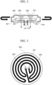
- FIG. 2 is a diagram for explaining a configuration of the base material 300.
- the base material 300 is mounted on the rotary stage 105 of the rotary device 100.
- the base material 300 includes a metal material such as aluminum (Al).
- a thermal spray film 201 is formed on the base material 300 by the thermal spray material sprayed from the thermal spray gun 20.
- a flow path 301 for circulating the liquid supplied from the liquid supply device 111 is arranged inside the base material 300.
- FIG. 3 is a diagram showing an example of the flow path 301 arranged in the base material 300.
- FIG. 3 is a diagram of the base material 300 viewed from the back surface side where the thermal spray film 201 is not formed.
- the flow path 301 includes an inlet 303 that receives the supply of the liquid from the liquid supply device 111, and an outlet 305 that returns the liquid circulated in the base material 300 along the flow path 301 to the liquid supply device 111.
- the inlet 303 is connected to a liquid supply port 119 (see FIG. 2 ) arranged in the rotary stage 105 and connected to the first pipe arranged in the rotary support 103.
- the outlet 305 is connected to a liquid discharge port 121 (see FIG.
- the flow path 301 is preferably arranged in the entire base material 300 along the circumferential direction of the base material 300.
- the shape of the base material 300 is not limited to a circular shape.
- the base material 300 is formed of a porous material 302.
- the porous material 302 may be a porous ceramic with a pore size of 10 to 200 ⁇ m.
- a through hole 307 connected to the suction pipe arranged in the rotary support 103 and connected to the air chuck device 113 may be arranged inside the base material 300.
- the through hole 307 connects to the porous material 302 portion of the base material 300.
- the base material 300 of the present embodiment is not limited to this, and the base material 300 may not include a porous material.
- the base material 300 can be fixed to the rotary stage 105 by a fixing tool such as a screw.
- the liquid supply device 111 supplies a liquid at a predetermined temperature to the base material 300 mounted on the rotary stage 105.
- a configuration of the liquid supply device 111 will be described with reference to FIG. 4 .
- FIG. 4 is a diagram for explaining the configuration of the liquid supply device 111.
- the liquid supply device 111 includes a hot-water tank 401, a cold-water tank 403, a heat exchanger 405, a DI water supply device 407, and a supply unit 409.
- a hot-water tank 401 a hot-water tank 401
- a cold-water tank 403 a heat exchanger 405
- DI water supply device 407 a DI water supply device 407
- a supply unit 409 In the present embodiment, an example in which water is used as a liquid used for adjusting the temperature of the base material 300 will be described.
- the rotary support 103 and the rotary stage 105 are not shown in FIG. 4 .
- the hot-water tank 401 temporarily stores hot water to be supplied to the base material 300.
- the hot water stored in the hot-water tank 401 is maintained at a temperature of about 20°C to 120°C.
- the hot-water tank 401 has a heater 411 for maintaining the temperature of the stored hot water.
- the hot-water tank 401 supplies hot water to the supply unit 409.
- the hot-water tank 401 collects the liquid circulated through the base material 300, and supplies a portion of the liquid to the cold-water tank 403.
- the liquid circulated through the base material 300 is collected in the hot-water tank 401 via the liquid discharge port arranged in the rotary stage 105 and the second pipe arranged in the rotary support 103.
- the hot-water tank 401 is connected to the second pipe arranged in the rotary support 103 via the rotary joint 115, and collects the liquid circulated through the base material 300 via the rotary joint 115.
- the cold-water tank 403 temporarily stores cold water to be supplied to the base material 300.
- the cold water stored in the cold-water tank 403 is maintained at a normal temperature (about 20°C to about 35°C).
- the cold-water tank 403 supplies cold water to the supply unit 409.
- the cold-water tank 403 receives the supply of hot water from the hot-water tank 401.
- the cold-water tank 403 supplies water including the supplied hot water to the heat exchanger 405.
- Cold water is supplied to the cold-water tank 403 from the heat exchanger 405.
- the cold-water tank 403 may supply the stored cold water to the DI water supply device 407.
- the heat exchanger 405 Water is supplied to the heat exchanger 405 from the cold-water tank 403.
- the heat exchanger 405 cools the supplied water and returns the cooled water to the cold-water tank 403.
- the heat exchanger 405 may be a radiator.
- the DI water supply device 407 purifies the water supplied from the cold-water tank 403.
- the DI water supply device 407 includes an ion exchange resin.
- the DI water supply device 407 returns the water purified by the ion exchange resin to the cold-water tank 403.
- the DI water supply device 407 may be omitted from the configuration of the liquid supply device 111.
- Hot water is supplied from the hot-water tank 401 and cold water from the cold-water tank 403 to the supply unit 409.
- the supply unit 409 mixes the supplied hot water and cold water to adjust the hot water to a predetermined temperature, and supplies the hot water to the base material 300 via the first pipe arranged in the rotary support 103 and the liquid supply port arranged in the rotary stage 105.
- the temperature of the hot water to be adjusted in the supply unit 409 is preferably in a range of 85°C or higher and 120°C or lower.
- the supply unit 409 is connected to the first pipe arranged in the rotary support 103 via the rotary joint 115, and supplies the temperature-adjusted hot water to the base material 300 via the rotary joint 115.
- the supply unit 409 may include a pressurizing device.
- the temperature of the hot water supplied to a base material 109 is adjusted to be higher than 100°C
- the temperature of the hot water can be adjusted to be higher than 100°C by pressurizing the hot water with the pressurizing device.
- the thermal spray film 201 is peeled off from the surface of the base material 300, or cracks occur in the thermal spray film 201.
- hot water adjusted to a predetermined temperature is supplied from the liquid supply device 111 to the base material 300.
- the hot water supplied to the base material 300 circulates through the entire base material 300 along the flow path 301 formed in the base material 300.
- the hot water flowing through the flow path 301 receives heat from the base material 300 which becomes hot during the thermal spray process, and suppresses the temperature rise of the base material 300. That is, the hot water supplied to the base material 300 functions as a heat medium. Therefore, the temperature difference between the base material 300 during the thermal spray process and after the thermal spray process is reduced, and the thermal stress generated in the base material 300 can be reduced. As a result, it is possible to prevent peeling of the thermal spray film and the occurrence of cracks.
- the temperature fluctuation of the base material 300 during the thermal spray process is reduced, and the residual stress in the thermal spray film to be formed is also reduced.
- the peeling resistance of the thermal spray film is improved, the variation in the quality of each individual product is reduced, and the reliability of the product manufactured by the thermal spraying apparatus 10 is improved.
- the liquid used to adjust the temperature of the base material 300 is not limited to water.
- a high boiling point material such as Galden or other liquid mediums may be used to adjust the temperature of the base material 300.
- the temperature of the liquid medium supplied from the liquid supply device 111 to the base material 300 is preferably in a range of 25°C or higher and 270°C or lower.
- the configuration of the liquid supply device 111 can be changed as appropriate depending on the type of the heat medium used to adjust the temperature of the base material 300.
- a configuration of the rotary device used is the same as the configuration of the rotary device 10 described with reference to FIG. 1 .
- a configuration of the liquid supply device included in the rotary device used is the same as the configuration of the liquid supply device 111 described with reference to FIG. 4 .
- a configuration of the base material used is the same as the configuration of the base material 300 described with reference to FIG. 2 and FIG. 3 .
- the main body was aluminum and the porous part 302 was used as the base material 300 made of aluminum oxide.
- Example 1 the temperature of the hot water supplied into the base material from the liquid supply device was set to 85°C, a water supply pressure from the liquid supply device to the base material was set to 3 atmospheres, and the temperature of the back surface side of the base material during the thermal spray process (the surface on which the thermal spray film is not formed) and the temperatures of a water supply port and a discharge port of the flow path arranged in the base material were measured.
- the thermal spray material sprayed from the thermal spray gun 200 onto the base material surface during the thermal spray process is aluminum oxide and its temperature is 1800°C to 2500°C.
- FIG. 5 shows the temperature of the base material back surface in Example 1 and the temperature of the water supply port and the discharge port of the flow path arranged in the base material.
- Example 1 using the rotary device according to the embodiment of the present disclosure, when hot water set to 85°C is supplied from the liquid supply device to the base material, the back surface temperature of the base material back surface during the thermal spray process is maintained at about 105°C.
- the temperature of the water supply port of the flow path was about 85°C, while the temperature of the discharge port was about 110°C.
- the hot water circulating in the flow path receives the heat from the surface side of the base material on which the thermal spray film is formed during the thermal spray process, and suppresses the temperature rise of the base material.
- the temperature difference between the base material during the thermal spray process and after the thermal spray process is reduced in Example 1. Therefore, it can be seen that the temperature of the base material during the thermal spray process can be effectively adjusted by using a liquid as the heat medium.
- the rotary device As described above, by the rotary device according to the embodiment of the present disclosure, it is possible to suppress the temperature rise of the base material during the thermal spray process and reduce the temperature difference between the base material during the thermal spray process and after the thermal spray process. As a result, the thermal stress generated in the base material can be reduced, and as a result, the thermal spray film can be prevented from being peeled off from the base material after the thermal spray process and the occurrence of cracks in the thermal spray film can be prevented, the quality of the thermal spray film can be improved, and the reliability of the product can be improved. In addition, since the thermal stress generated during the thermal spray process is small, the quality of the base material including the thermal spray film is improved, and the reliability of the base material is improved when the base material is actually used.
- a pressurized gas may be supplied from a gas supply device (gas supply unit) to the base material 300.
- the rotary device 100 may include the gas supply device in addition to the liquid supply device 111.
- the gas supply device may supply water vapor as a pressurized gas to the base material 300.
- the gas supply device can be configured substantially in the same manner as the configuration of the liquid supply device 111 shown in FIG. 4 , except that the hot-water tank (the hot-water tank 401 in FIG. 4 ) is omitted, and instead, the cold water supplied from the cold-water tank (the cold-water tank 403 in FIG. 4 ) is heated to generate steam by a boiler and supplied to the base material 300.
- the steam generated by the boiler may be mixed with hot air before being supplied to the base material 300 to adjust the temperature.
- the gas supplied from the gas supply device is not limited to water vapor.
- the gas supply device supplies a gas of about 85°C to about 145°C.
- the gas supply device may supply pressurized gas to the base material 300 before the thermal spray process.
- the gas supply device can efficiently adjust the temperature of the base material 300 by supplying the pressurized gas to the base material 300 before the start of thermal spray.
- the rotary device 100 By adjusting the temperature of the base material 300 to a desired temperature by the gas supplied from the gas supply device before the start of thermal spraying, it is possible to prevent the temperature of the base material 300 from suddenly rising after the start of thermal spraying, and to reduce the thermal stress generated in the base material 300 before and after the start of thermal spraying. Furthermore, in order to adjust the temperature of the base material 300 during the thermal spray process, after the start of thermal spraying, that is, during the thermal spray process, the rotary device 100 preferably receives the supply of hot water as a heat medium from the liquid supply device 111 according to the above-described embodiment.
- the rotary device 100 may adjust the base material 300 to a desired temperature by receiving the supply of gas from the gas supply device before the start of thermal spraying, and may adjust the base material 300 on which the thermal spray film is formed to a desired temperature by receiving the supply of hot water from the liquid supply device 111 after the start of thermal spraying (during the thermal spray process).
- the connection between the gas supply device and the liquid supply device 111 and the rotary joint 115 may be switched between before the start of thermal spraying and after the start of thermal spraying.
- the present disclosure is not limited to this.
- the liquid supply device of the present embodiment may be applied to control the temperature of the base material.
- thermal spraying device 100: rotary device, 101, rotary table, 103, rotary support, 105: rotary stage, 300: base material (workpiece), 111: liquid supply device, 113: air chuck device, 115: rotary joint, 117: rotary mechanism, 200: spray gun, 301: flow path, 303: inlet, 305: outlet, 401: hot-water tank, 403: cold-water tank, 405: heat exchanger, 407: DI water supply device, 409: supply unit
Landscapes
- Chemical & Material Sciences (AREA)
- Engineering & Computer Science (AREA)
- Mechanical Engineering (AREA)
- Physics & Mathematics (AREA)
- Plasma & Fusion (AREA)
- Chemical Kinetics & Catalysis (AREA)
- Materials Engineering (AREA)
- Metallurgy (AREA)
- Organic Chemistry (AREA)
- Thermal Sciences (AREA)
- General Engineering & Computer Science (AREA)
- Coating Apparatus (AREA)
- Coating By Spraying Or Casting (AREA)
- Nozzles (AREA)
Abstract
Description
- An embodiment of the present disclosure relates to a rotary device and a thermal spraying apparatus.
- A thermal spraying device is known in which a film-forming material such as a metal or a ceramic is heated to be melted or brought into a state close to melting (semi-molten), and the film-forming material that is melted or brought into the semi-molten state is sprayed onto a base material, thereby forming a film of the film-forming material on a base material. For example, Patent Literature 1 and Patent Literature 2 disclose a thermal spraying device in which a workpiece is rotated, and a molten metal is adhered to a surface thereof to form a metal coating layer.
-
- Patent Literature 1:
Japanese unexamined utility model application publication No. S58-35961 - Patent Literature 2:
Japanese laid-open patent publication No. S58-039772 - The properties of a film formed by thermal spray are greatly affected by the conditions at the time of film formation. One of the conditions is the temperature of a base material on which the film is formed. In a thermal spray process, the film-forming material in a molten state or a semi-molten state is sprayed, so that the base material becomes hot. When the thermal spray is completed, the temperature of the base material decreases. When the temperature of the base material decreases, thermal stress is generated in the base material, causing problems such as the film peeling off from a surface of the base material, and cracks occurring in the film.
- It is an object of embodiments of the present disclosure to provide a rotary device and a thermal spraying apparatus capable of reducing thermal stress of the base material and preventing peeling of the film from the base material and cracking of the film.
- A rotary device according to an embodiment of the present disclosure comprises a rotary stage detachably supporting a base material having an inlet, an outlet, and a flow path connecting the inlet and the outlet of a liquid at a predetermined temperature, the rotary stage having a liquid supply port supplying the liquid to the base material and a liquid discharge port discharging the liquid from the base material, a rotary support supporting the rotary table, the rotary support having a first pipe connected to the liquid supply port and a second pipe connected to the liquid discharge port inside, a rotary mechanism rotating the rotary support and a liquid supply part supplying the liquid to the base material.
- A thermal spraying apparatus according to an embodiment of the present disclosure comprises the rotary device described above and a thermal spray gun.
- According to an embodiment of the present disclosure, it is possible to provide a rotary device and a thermal spraying apparatus capable of reducing thermal stress of a base material and preventing peeling of the film from the base material and cracking of the film.
-
-
FIG. 1 is a diagram for explaining a configuration of a thermal spraying apparatus according to an embodiment of the present disclosure. -
FIG. 2 is a diagram for explaining a configuration of a base material attached to a rotary device according to an embodiment of the present disclosure. -
FIG. 3 is a diagram showing an example of a flow path of a liquid arranged in a base material. -
FIG. 4 is a diagram for explaining a configuration of a liquid supply device. -
FIG. 5 is a graph showing the progress of a temperature of a base material back surface and temperatures of a water supply port and discharge port of a flow path arranged in a base material in Example 1. - Hereinafter, embodiments of the present disclosure will be described with reference to the drawings and the like. However, the present invention can be implemented in many different aspects, and should not be construed as being limited to the description of the embodiments exemplified below. In order to make the description clearer, the drawings may be schematically represented with respect to the width, thickness, shape, and the like of each part as compared with the actual embodiment, but are merely examples, and do not limit the interpretation of the present disclosure.
- In the drawings, the widths, thicknesses, shapes, and the like of the respective portions may be schematically represented in comparison with the actual embodiments for clarity of explanation, but the drawings are merely examples, and do not limit the interpretation of the present invention. Furthermore, in the present specification and the drawings, elements having the same functions as those described with respect to the above-described drawings are denoted by the same reference signs, and redundant descriptions thereof may be omitted. Furthermore, in the present specification and the drawings, the same or similar parts are denoted by the same reference signs or similar reference signs (reference signs denoted by A, B, and the like after numerals) and repeated description thereof may be omitted.
- In the present specification, in the case where a member or region is "above (or below)" another member or region, it includes the case where it is directly above (or below) the other member or region, but also the case where it is above (or below) the other member or region, that is, the case where another component is included between above (or below) the other member or region.
- Furthermore, in the present specification, the expressions "α includes A, B or C," "α includes any of A, B and C," and "α includes one selected from a group consisting of A, B, and C" do not exclude the case where α includes a plurality of combinations of A to C unless otherwise specified. Furthermore, these expressions do not exclude the case where α includes other elements.
- Hereinafter, a
thermal spraying apparatus 10 according to an embodiment of the present disclosure will be described with reference to the drawings. -
FIG. 1 is a diagram for explaining a configuration of thethermal spraying apparatus 10 according to an embodiment of the present disclosure. Thethermal spraying apparatus 10 includes arotary device 100 that supports abase material 300, and athermal spray gun 200 that sprays a thermal spray material onto a surface of thebase material 300. - The
rotary device 100 includes aframe 101, arotary support 103, arotary stage 105, a liquid supply device (liquid supply unit) 111, anair chuck device 113, and arotary mechanism 117. - The
liquid supply device 111, theair chuck device 113, and therotary mechanism 117 are installed on theframe 101. Theframe 101 may be a housing. - The
liquid supply device 111 supplies a liquid adjusted to a predetermined temperature range to thebase material 300. In addition, theliquid supply device 111 collects the liquid circulated through thebase material 300, and adjusts the collected liquid again to the predetermined temperature range. Theliquid supply device 111 supplies the liquid to thebase material 300 and collects the liquid from thebase material 300 through pipes (not shown) arranged in therotary stage 105 and therotary support 103. The pipes may be a hollow-path arranged in therotary stage 105 and therotary support 103. A detailed configuration of theliquid supply device 111 will be described later. - The
rotary mechanism 117 is connected to therotary support 103, which will be described later. Therotary mechanism 117 includes a driving device such as a motor. Therotary mechanism 117 rotates therotary stage 105, which is fixed to therotary support 103, around therotary support 103 as an axis. - The
air chuck device 113 vacuum-chucks thebase material 300 formed at least in part of a porous material through a pipe (suction pipe, not shown) arranged in therotary stage 105 and therotary support 103, and fixes thebase material 300 on therotary stage 105. The pipe may be a hollow-path arranged in therotary stage 105 and therotary support 103. Theair chuck device 113 may include a vacuum pump connected to the pipe arranged in therotary support 103. - The
rotary support 103 supports therotary stage 105, which will be described later. Although not shown, a pipe (first pipe) for supplying a liquid from theliquid supply device 111 to thebase material 300, a pipe (second pipe) for collecting the liquid circulated through thebase material 300 to theliquid supply device 111, and a pipe (suction pipe) connected to theair chuck device 113 are arranged inside therotary support 103. These pipes may be hollow passes arranged inside therotary support 103. The first pipe, the second pipe, and the suction pipe arranged inside therotary support 103 are connected to theliquid supply device 111 and theair chuck device 113 via arotary joint 115, respectively. - The
rotary support 103 is connected to therotary mechanism 117. Therotary support 103 functions as a shaft, and is capable of rotating therotary stage 105 and thebase material 300 mounted on therotary stage 105 around the long axis direction of therotary support 103. - The
rotary support 103 may have a connectingportion 107 connected to therotary stage 105. The connectingportion 107 may be connected to a position control mechanism such as an actuator. In this case, the connectingportion 107 can tilt therotary stage 105 and thebase material 300 mounted on therotary stage 105 at a predetermined angle relative to thethermal spray gun 200. - The
rotary stage 105 is fixed to therotary support 103. Therotary stage 105 may be fixed to therotary support 103 to be tiltable. Therotary stage 105 detachably supports thebase material 300. In a thermal spray process, therotary stage 105 rotates together with thebase material 300 by therotary support 103 connected to the rotary mechanism. In this case, therotary stage 105 may be tilted at a predetermined angle relative to thethermal spray gun 200 that sprays the thermal spray material onto thebase material 300. Although not shown, a liquid supply port connected to a first pipe arranged in therotary support 103 and supplying the liquid supplied through the first pipe to thebase material 300, and a liquid discharge port connected to the second pipe arranged in therotary support 103 and discharging the liquid circulated through thebase material 300 are arranged in therotary stage 105. The liquid supply port is arranged to be aligned with the first pipe and an inlet (303) arranged in thebase material 300 described later. Similarly, the liquid discharge port is arranged to be aligned with the second pipe and an outlet (305) arranged in thebase material 300 described below. -
FIG. 2 is a diagram for explaining a configuration of thebase material 300. Thebase material 300 is mounted on therotary stage 105 of therotary device 100. For example, thebase material 300 includes a metal material such as aluminum (Al). Athermal spray film 201 is formed on thebase material 300 by the thermal spray material sprayed from thethermal spray gun 20. As shown inFIG. 2 , aflow path 301 for circulating the liquid supplied from theliquid supply device 111 is arranged inside thebase material 300. -
FIG. 3 is a diagram showing an example of theflow path 301 arranged in thebase material 300.FIG. 3 is a diagram of thebase material 300 viewed from the back surface side where thethermal spray film 201 is not formed. Theflow path 301 includes aninlet 303 that receives the supply of the liquid from theliquid supply device 111, and anoutlet 305 that returns the liquid circulated in thebase material 300 along theflow path 301 to theliquid supply device 111. Theinlet 303 is connected to a liquid supply port 119 (seeFIG. 2 ) arranged in therotary stage 105 and connected to the first pipe arranged in therotary support 103. Theoutlet 305 is connected to a liquid discharge port 121 (seeFIG. 2 ) connected to the second pipe arranged in therotary support 103. In the case where thebase material 300 is circular, as shown inFIG. 3 , theflow path 301 is preferably arranged in theentire base material 300 along the circumferential direction of thebase material 300. Although the case where thebase material 300 is circular is shown inFIG. 3 , the shape of thebase material 300 is not limited to a circular shape. - At least a portion of the
base material 300 is formed of aporous material 302. For example, theporous material 302 may be a porous ceramic with a pore size of 10 to 200 µm. A throughhole 307 connected to the suction pipe arranged in therotary support 103 and connected to theair chuck device 113 may be arranged inside thebase material 300. The throughhole 307 connects to theporous material 302 portion of thebase material 300. In addition, thebase material 300 of the present embodiment is not limited to this, and thebase material 300 may not include a porous material. In this case, thebase material 300 can be fixed to therotary stage 105 by a fixing tool such as a screw. - The
liquid supply device 111 supplies a liquid at a predetermined temperature to thebase material 300 mounted on therotary stage 105. Hereinafter, a configuration of theliquid supply device 111 will be described with reference toFIG. 4 . -
FIG. 4 is a diagram for explaining the configuration of theliquid supply device 111. Theliquid supply device 111 includes a hot-water tank 401, a cold-water tank 403, aheat exchanger 405, a DIwater supply device 407, and asupply unit 409. In the present embodiment, an example in which water is used as a liquid used for adjusting the temperature of thebase material 300 will be described. Therotary support 103 and therotary stage 105 are not shown inFIG. 4 . - The hot-
water tank 401 temporarily stores hot water to be supplied to thebase material 300. The hot water stored in the hot-water tank 401 is maintained at a temperature of about 20°C to 120°C. The hot-water tank 401 has aheater 411 for maintaining the temperature of the stored hot water. The hot-water tank 401 supplies hot water to thesupply unit 409. The hot-water tank 401 collects the liquid circulated through thebase material 300, and supplies a portion of the liquid to the cold-water tank 403. The liquid circulated through thebase material 300 is collected in the hot-water tank 401 via the liquid discharge port arranged in therotary stage 105 and the second pipe arranged in therotary support 103. The hot-water tank 401 is connected to the second pipe arranged in therotary support 103 via the rotary joint 115, and collects the liquid circulated through thebase material 300 via the rotary joint 115. - The cold-
water tank 403 temporarily stores cold water to be supplied to thebase material 300. The cold water stored in the cold-water tank 403 is maintained at a normal temperature (about 20°C to about 35°C). The cold-water tank 403 supplies cold water to thesupply unit 409. In addition, the cold-water tank 403 receives the supply of hot water from the hot-water tank 401. The cold-water tank 403 supplies water including the supplied hot water to theheat exchanger 405. Cold water is supplied to the cold-water tank 403 from theheat exchanger 405. In addition, the cold-water tank 403 may supply the stored cold water to the DIwater supply device 407. - Water is supplied to the
heat exchanger 405 from the cold-water tank 403. Theheat exchanger 405 cools the supplied water and returns the cooled water to the cold-water tank 403. Theheat exchanger 405 may be a radiator. - The DI
water supply device 407 purifies the water supplied from the cold-water tank 403. The DIwater supply device 407 includes an ion exchange resin. The DIwater supply device 407 returns the water purified by the ion exchange resin to the cold-water tank 403. According to an embodiment, the DIwater supply device 407 may be omitted from the configuration of theliquid supply device 111. - Hot water is supplied from the hot-
water tank 401 and cold water from the cold-water tank 403 to thesupply unit 409. Thesupply unit 409 mixes the supplied hot water and cold water to adjust the hot water to a predetermined temperature, and supplies the hot water to thebase material 300 via the first pipe arranged in therotary support 103 and the liquid supply port arranged in therotary stage 105. The temperature of the hot water to be adjusted in thesupply unit 409 is preferably in a range of 85°C or higher and 120°C or lower. Thesupply unit 409 is connected to the first pipe arranged in therotary support 103 via the rotary joint 115, and supplies the temperature-adjusted hot water to thebase material 300 via the rotary joint 115. - The
supply unit 409 may include a pressurizing device. In the case where the temperature of the hot water supplied to a base material 109 is adjusted to be higher than 100°C, the temperature of the hot water can be adjusted to be higher than 100°C by pressurizing the hot water with the pressurizing device. - If the temperature difference between the
base material 300 during the thermal spray process in which the thermal spray material in a molten state or a semi-molten state is sprayed from thethermal spray gun 20 and after the thermal spray is completed is large, there is a possibility that a thermal stress is generated in thebase material 300, thethermal spray film 201 is peeled off from the surface of thebase material 300, or cracks occur in thethermal spray film 201. - In the present embodiment, hot water adjusted to a predetermined temperature is supplied from the
liquid supply device 111 to thebase material 300. The hot water supplied to thebase material 300 circulates through theentire base material 300 along theflow path 301 formed in thebase material 300. The hot water flowing through theflow path 301 receives heat from thebase material 300 which becomes hot during the thermal spray process, and suppresses the temperature rise of thebase material 300. That is, the hot water supplied to thebase material 300 functions as a heat medium. Therefore, the temperature difference between thebase material 300 during the thermal spray process and after the thermal spray process is reduced, and the thermal stress generated in thebase material 300 can be reduced. As a result, it is possible to prevent peeling of the thermal spray film and the occurrence of cracks. In addition, the temperature fluctuation of thebase material 300 during the thermal spray process is reduced, and the residual stress in the thermal spray film to be formed is also reduced. As a result, the peeling resistance of the thermal spray film is improved, the variation in the quality of each individual product is reduced, and the reliability of the product manufactured by thethermal spraying apparatus 10 is improved. - In the above embodiment, the example in which water is used as the liquid supplied from the
liquid supply device 111 to thebase material 300 has been described. However, the liquid used to adjust the temperature of thebase material 300 is not limited to water. For example, a high boiling point material such as Galden or other liquid mediums may be used to adjust the temperature of thebase material 300. In this case, the temperature of the liquid medium supplied from theliquid supply device 111 to thebase material 300 is preferably in a range of 25°C or higher and 270°C or lower. The configuration of theliquid supply device 111 can be changed as appropriate depending on the type of the heat medium used to adjust the temperature of thebase material 300. - The temperature of the base material in the case where the rotary device according to an embodiment of the present disclosure is used is verified. A configuration of the rotary device used is the same as the configuration of the
rotary device 10 described with reference toFIG. 1 . In addition, a configuration of the liquid supply device included in the rotary device used is the same as the configuration of theliquid supply device 111 described with reference toFIG. 4 . A configuration of the base material used is the same as the configuration of thebase material 300 described with reference toFIG. 2 and FIG. 3 . The main body was aluminum and theporous part 302 was used as thebase material 300 made of aluminum oxide. - In Example 1, the temperature of the hot water supplied into the base material from the liquid supply device was set to 85°C, a water supply pressure from the liquid supply device to the base material was set to 3 atmospheres, and the temperature of the back surface side of the base material during the thermal spray process (the surface on which the thermal spray film is not formed) and the temperatures of a water supply port and a discharge port of the flow path arranged in the base material were measured. The thermal spray material sprayed from the
thermal spray gun 200 onto the base material surface during the thermal spray process is aluminum oxide and its temperature is 1800°C to 2500°C.FIG. 5 shows the temperature of the base material back surface in Example 1 and the temperature of the water supply port and the discharge port of the flow path arranged in the base material. - Referring to
FIG. 5 , in Example 1 using the rotary device according to the embodiment of the present disclosure, when hot water set to 85°C is supplied from the liquid supply device to the base material, the back surface temperature of the base material back surface during the thermal spray process is maintained at about 105°C. In addition, the temperature of the water supply port of the flow path was about 85°C, while the temperature of the discharge port was about 110°C. This means that the hot water circulating in the flow path receives the heat from the surface side of the base material on which the thermal spray film is formed during the thermal spray process, and suppresses the temperature rise of the base material. This result suggests that the temperature difference between the base material during the thermal spray process and after the thermal spray process is reduced in Example 1. Therefore, it can be seen that the temperature of the base material during the thermal spray process can be effectively adjusted by using a liquid as the heat medium. - As described above, by the rotary device according to the embodiment of the present disclosure, it is possible to suppress the temperature rise of the base material during the thermal spray process and reduce the temperature difference between the base material during the thermal spray process and after the thermal spray process. As a result, the thermal stress generated in the base material can be reduced, and as a result, the thermal spray film can be prevented from being peeled off from the base material after the thermal spray process and the occurrence of cracks in the thermal spray film can be prevented, the quality of the thermal spray film can be improved, and the reliability of the product can be improved. In addition, since the thermal stress generated during the thermal spray process is small, the quality of the base material including the thermal spray film is improved, and the reliability of the base material is improved when the base material is actually used.
- In the embodiment of the present disclosure described above, although the case where the liquid is supplied from the
liquid supply device 111 to thebase material 300 provided on therotary device 100 has been described, the present disclosure is not limited to this. For example, a pressurized gas may be supplied from a gas supply device (gas supply unit) to thebase material 300. - In the thermal spraying apparatus according to the modification of the present disclosure, the
rotary device 100 may include the gas supply device in addition to theliquid supply device 111. For example, the gas supply device may supply water vapor as a pressurized gas to thebase material 300. In this case, the gas supply device can be configured substantially in the same manner as the configuration of theliquid supply device 111 shown inFIG. 4 , except that the hot-water tank (the hot-water tank 401 inFIG. 4 ) is omitted, and instead, the cold water supplied from the cold-water tank (the cold-water tank 403 inFIG. 4 ) is heated to generate steam by a boiler and supplied to thebase material 300. In addition, the steam generated by the boiler may be mixed with hot air before being supplied to thebase material 300 to adjust the temperature. Furthermore, the gas supplied from the gas supply device is not limited to water vapor. For example, the gas supply device supplies a gas of about 85°C to about 145°C. - The gas supply device may supply pressurized gas to the
base material 300 before the thermal spray process. The gas supply device can efficiently adjust the temperature of thebase material 300 by supplying the pressurized gas to thebase material 300 before the start of thermal spray. - By adjusting the temperature of the
base material 300 to a desired temperature by the gas supplied from the gas supply device before the start of thermal spraying, it is possible to prevent the temperature of thebase material 300 from suddenly rising after the start of thermal spraying, and to reduce the thermal stress generated in thebase material 300 before and after the start of thermal spraying. Furthermore, in order to adjust the temperature of thebase material 300 during the thermal spray process, after the start of thermal spraying, that is, during the thermal spray process, therotary device 100 preferably receives the supply of hot water as a heat medium from theliquid supply device 111 according to the above-described embodiment. - As described above, the
rotary device 100 may adjust thebase material 300 to a desired temperature by receiving the supply of gas from the gas supply device before the start of thermal spraying, and may adjust thebase material 300 on which the thermal spray film is formed to a desired temperature by receiving the supply of hot water from theliquid supply device 111 after the start of thermal spraying (during the thermal spray process). In this case, in therotary device 100, the connection between the gas supply device and theliquid supply device 111 and the rotary joint 115 may be switched between before the start of thermal spraying and after the start of thermal spraying. - The addition, deletion, or design change of components as appropriate by those skilled in the art based on the embodiment and modification are also included in the scope of the present invention as long as they are provided with the gist of the present invention.
- In the embodiment of the present disclosure described above, although the case where the rotary device includes the liquid supply device has been described, the present disclosure is not limited to this. For example, in a device that performs a process of being heated to about 200°C in addition to the rotary device used for the thermal spraying, the liquid supply device of the present embodiment may be applied to control the temperature of the base material.
- Furthermore, it is understood that, even if the effect is different from those provided by each of the above-described embodiments, the effect obvious from the description in the specification or easily predicted by persons ordinarily skilled in the art is apparently derived from the present invention.
- 10: thermal spraying device, 100: rotary device, 101, rotary table, 103, rotary support, 105: rotary stage, 300: base material (workpiece), 111: liquid supply device, 113: air chuck device, 115: rotary joint, 117: rotary mechanism, 200: spray gun, 301: flow path, 303: inlet, 305: outlet, 401: hot-water tank, 403: cold-water tank, 405: heat exchanger, 407: DI water supply device, 409: supply unit
Claims (16)
- A rotary device comprising:a rotary stage detachably supporting a base material having an inlet, an outlet, and a flow path connecting the inlet and the outlet of a liquid at a predetermined temperature, the rotary stage having a liquid supply port supplying the liquid to the base material and a liquid discharge port discharging the liquid from the base material;a rotary support supporting the rotary table, the rotary support having a first pipe connected to the liquid supply port and a second pipe connected to the liquid discharge port inside;a rotary mechanism rotating the rotary support; anda liquid supply part supplying the liquid to the base material.
- The rotary device according to claim 1, wherein the liquid supply part comprises:a hot-water tank supplying hot-water at a relatively high temperature;a cold-water tank supplying cold-water at a relatively low temperature; anda supply unit mixing the hot-water supplied from the hot-water tank and the cold-water supplied from the cold-water tank, adjusting the mixed water to a predetermined temperature, and supplying the water to the base material.
- The rotary device according to claim 2, wherein the liquid supply part further comprises a pressurizing device pressurizing the water adjusted to the predetermined temperature.
- The rotary device according to any one of claims 1 to 3, wherein the liquid supply part further comprises a heat exchanger providing room temperature water to the cold-water tank.
- The rotary device according to any one of claims 1 to 4, wherein the predetermined temperature is in a range of 85°C or higher and 120°C or lower.
- The rotary device according to claim 1, wherein the predetermined temperature is in a range of 25°C or higher and 270°C or lower.
- The rotary device according to any one of claims 1 to 6, wherein the liquid supply part supplies the liquid to the base material via the first pipe and collects the liquid from the base material via the second pipe while the rotary stage is rotating.
- The rotary device according to claim 7, wherein the first pipe is connected to the liquid supply part via a rotary joint.
- The rotary device according to any one of claims 1 to 8, wherein the liquid supply port is arranged to be aligned with the inlet and the liquid discharge port is arranged to be aligned with the outlet.
- The rotary device according to any one of claims 1 to 9, further comprising: a chuck mechanism holding the base material on the rotary table.
- The rotary device according to claim 10, wherein the chuck mechanism is a vacuum chuck mechanism, and the vacuum chuck mechanism comprises:a through hole arranged in the rotary stage,a suction pipe arranged in the rotary support and connected to the through hole; anda vacuum pump connected to the suction pipe.
- The rotary device according to claim 11, wherein at least a portion of the base material contains a porous material.
- The rotary device according to claim 11, wherein the suction pipe is connected to the vacuum pump via a rotary joint.
- A thermal spraying apparatus comprising:the rotary device according to claims 1 to 13, anda thermal spray gun.
- The thermal spraying apparatus according to claim 14, whereinthe thermal spray gun sprays a thermal spray material onto a surface of the base material supported by the rotary stage; andthe liquid supply part supplies the liquid to the base material while the thermal spray material is sprayed from the thermal spray gun.
- The thermal spraying apparatus according to claim 15, wherein the rotary device further comprises a gas supply unit supplying a pressurized gas to the base material, and the gas supply unit supplies the gas to the base material before the thermal spray material is sprayed from the thermal spray gun.
Applications Claiming Priority (2)
| Application Number | Priority Date | Filing Date | Title |
|---|---|---|---|
| JP2022052502A JP7702912B2 (en) | 2022-03-28 | 2022-03-28 | Rotating and thermal spraying equipment |
| PCT/JP2023/007341 WO2023189116A1 (en) | 2022-03-28 | 2023-02-28 | Rotary device and spray device |
Publications (2)
| Publication Number | Publication Date |
|---|---|
| EP4502225A1 true EP4502225A1 (en) | 2025-02-05 |
| EP4502225A4 EP4502225A4 (en) | 2025-08-06 |
Family
ID=88200626
Family Applications (1)
| Application Number | Title | Priority Date | Filing Date |
|---|---|---|---|
| EP23779146.2A Pending EP4502225A4 (en) | 2022-03-28 | 2023-02-28 | ROTATION DEVICE AND SPRAY DEVICE |
Country Status (7)
| Country | Link |
|---|---|
| US (1) | US20250011913A1 (en) |
| EP (1) | EP4502225A4 (en) |
| JP (1) | JP7702912B2 (en) |
| KR (1) | KR20240164931A (en) |
| CN (1) | CN118974304A (en) |
| TW (1) | TWI901942B (en) |
| WO (1) | WO2023189116A1 (en) |
Family Cites Families (13)
| Publication number | Priority date | Publication date | Assignee | Title |
|---|---|---|---|---|
| JPS5835961U (en) | 1981-08-31 | 1983-03-09 | 本田技研工業株式会社 | Rotary drive device in thermal spray equipment |
| JPS5839772A (en) | 1981-08-31 | 1983-03-08 | Honda Motor Co Ltd | Method and device for melt spraying of metal |
| US5436426A (en) * | 1993-04-19 | 1995-07-25 | Sulzer Metco (Us), Inc. | Fixture and method for cooling tubular substrate during thermal spraying |
| US6689221B2 (en) * | 2000-12-04 | 2004-02-10 | Applied Materials, Inc. | Cooling gas delivery system for a rotatable semiconductor substrate support assembly |
| JP4464779B2 (en) * | 2004-09-22 | 2010-05-19 | 株式会社ダイヘン | Thermal spray equipment |
| KR100782380B1 (en) * | 2005-01-24 | 2007-12-07 | 삼성전자주식회사 | Semiconductor manufacturing device |
| US7479210B2 (en) * | 2005-04-14 | 2009-01-20 | Tango Systems, Inc. | Temperature control of pallet in sputtering system |
| US7189335B1 (en) | 2005-08-31 | 2007-03-13 | Honeywell International Inc. | Conformal coverings for electronic devices |
| CN201756581U (en) * | 2010-06-28 | 2011-03-09 | 山东科技大学 | Wear-resisting coating spraying fixture for coating scraper |
| JP2017069429A (en) | 2015-09-30 | 2017-04-06 | 株式会社東京精密 | High accuracy wafer processing device |
| KR20180098339A (en) * | 2015-12-29 | 2018-09-03 | 코닝 인코포레이티드 | Electrostatic Chucking of Cover Glass Substrate in Vacuum Coating Process |
| US11837479B2 (en) | 2016-05-05 | 2023-12-05 | Applied Materials, Inc. | Advanced temperature control for wafer carrier in plasma processing chamber |
| WO2020179539A1 (en) * | 2019-03-01 | 2020-09-10 | 日本発條株式会社 | Stage, and method for manufacturing stage |
-
2022
- 2022-03-28 JP JP2022052502A patent/JP7702912B2/en active Active
-
2023
- 2023-02-28 EP EP23779146.2A patent/EP4502225A4/en active Pending
- 2023-02-28 WO PCT/JP2023/007341 patent/WO2023189116A1/en not_active Ceased
- 2023-02-28 KR KR1020247034617A patent/KR20240164931A/en active Pending
- 2023-02-28 CN CN202380029407.4A patent/CN118974304A/en active Pending
- 2023-03-17 TW TW112109926A patent/TWI901942B/en active
-
2024
- 2024-09-26 US US18/898,406 patent/US20250011913A1/en active Pending
Also Published As
| Publication number | Publication date |
|---|---|
| JP2023145172A (en) | 2023-10-11 |
| TWI901942B (en) | 2025-10-21 |
| TW202403070A (en) | 2024-01-16 |
| EP4502225A4 (en) | 2025-08-06 |
| KR20240164931A (en) | 2024-11-21 |
| WO2023189116A1 (en) | 2023-10-05 |
| US20250011913A1 (en) | 2025-01-09 |
| CN118974304A (en) | 2024-11-15 |
| JP7702912B2 (en) | 2025-07-04 |
Similar Documents
| Publication | Publication Date | Title |
|---|---|---|
| JP7649818B2 (en) | Substrate Carrier Using Proportional Thermal Fluid Delivery System | |
| US6090261A (en) | Method and apparatus for controlling plating over a face of a substrate | |
| US20140364040A1 (en) | Substrate polishing apparatus, substrate polishing method, and apparatus for regulating temperature of polishing surface of polishing pad used in polishing apparatus | |
| US6042712A (en) | Apparatus for controlling plating over a face of a substrate | |
| JP4745961B2 (en) | Substrate support having temperature-controlled substrate support surface, control method thereof, semiconductor processing apparatus and method | |
| JP5162621B2 (en) | Temperature control device, cooling device, and method of manufacturing temperature control device | |
| RU2751016C1 (en) | Reflow soldering system for combined convection soldering and condensation soldering | |
| US8029865B2 (en) | Method for coating or heat treatment of blisks for aircraft gas turbines | |
| JP2014053645A (en) | Vacuum chucking heater of axisymmetrical and uniform thermal profile | |
| US20190326139A1 (en) | Ceramic wafer heater having cooling channels with minimum fluid drag | |
| KR102929686B1 (en) | Substrate processing device and method | |
| EP1593752B1 (en) | Multi-component coating deposition | |
| CN109514145B (en) | Aeroengine blade surfacing repair cooling system and cooling method | |
| US20250011913A1 (en) | Rotary device and thermal spraying apparatus | |
| JP2025062091A (en) | Substrate Processing System | |
| US20100104766A1 (en) | Method for use with a coating process | |
| TW202341322A (en) | Temperature regulating device for semiconductor manufacturing equipment, and semiconductor manufacturing system | |
| JP7187303B2 (en) | temperature controller | |
| WO2002102519A1 (en) | Adjustable injector assembly for melted powder coating | |
| JP4313206B2 (en) | Method for providing a protective coating on a component of a large machine | |
| JP5513810B2 (en) | Mandrel for easy sheet manufacturing | |
| JP2005534545A5 (en) | ||
| JP2021130841A (en) | Glass material spraying device | |
| JP2005126809A (en) | Method for cooling high-temperature metal | |
| JP2023145172A5 (en) |
Legal Events
| Date | Code | Title | Description |
|---|---|---|---|
| STAA | Information on the status of an ep patent application or granted ep patent |
Free format text: STATUS: THE INTERNATIONAL PUBLICATION HAS BEEN MADE |
|
| PUAI | Public reference made under article 153(3) epc to a published international application that has entered the european phase |
Free format text: ORIGINAL CODE: 0009012 |
|
| STAA | Information on the status of an ep patent application or granted ep patent |
Free format text: STATUS: REQUEST FOR EXAMINATION WAS MADE |
|
| 17P | Request for examination filed |
Effective date: 20241021 |
|
| AK | Designated contracting states |
Kind code of ref document: A1 Designated state(s): AL AT BE BG CH CY CZ DE DK EE ES FI FR GB GR HR HU IE IS IT LI LT LU LV MC ME MK MT NL NO PL PT RO RS SE SI SK SM TR |
|
| DAV | Request for validation of the european patent (deleted) | ||
| DAX | Request for extension of the european patent (deleted) | ||
| A4 | Supplementary search report drawn up and despatched |
Effective date: 20250704 |
|
| RIC1 | Information provided on ipc code assigned before grant |
Ipc: C23C 4/12 20160101AFI20250630BHEP Ipc: B05B 13/02 20060101ALI20250630BHEP Ipc: B05D 3/02 20060101ALI20250630BHEP Ipc: C23C 4/123 20160101ALI20250630BHEP |