EP4502224A1 - Hot-stamped component having high cold-bending performance and high strength, and manufacturing method therefor - Google Patents
Hot-stamped component having high cold-bending performance and high strength, and manufacturing method therefor Download PDFInfo
- Publication number
- EP4502224A1 EP4502224A1 EP23778119.0A EP23778119A EP4502224A1 EP 4502224 A1 EP4502224 A1 EP 4502224A1 EP 23778119 A EP23778119 A EP 23778119A EP 4502224 A1 EP4502224 A1 EP 4502224A1
- Authority
- EP
- European Patent Office
- Prior art keywords
- hot
- component
- stamped
- strength
- stamped component
- Prior art date
- Legal status (The legal status is an assumption and is not a legal conclusion. Google has not performed a legal analysis and makes no representation as to the accuracy of the status listed.)
- Pending
Links
Images
Classifications
-
- C—CHEMISTRY; METALLURGY
- C21—METALLURGY OF IRON
- C21D—MODIFYING THE PHYSICAL STRUCTURE OF FERROUS METALS; GENERAL DEVICES FOR HEAT TREATMENT OF FERROUS OR NON-FERROUS METALS OR ALLOYS; MAKING METAL MALLEABLE, e.g. BY DECARBURISATION OR TEMPERING
- C21D9/00—Heat treatment, e.g. annealing, hardening, quenching or tempering, adapted for particular articles; Furnaces therefor
- C21D9/46—Heat treatment, e.g. annealing, hardening, quenching or tempering, adapted for particular articles; Furnaces therefor for sheet metals
-
- B—PERFORMING OPERATIONS; TRANSPORTING
- B21—MECHANICAL METAL-WORKING WITHOUT ESSENTIALLY REMOVING MATERIAL; PUNCHING METAL
- B21D—WORKING OR PROCESSING OF SHEET METAL OR METAL TUBES, RODS OR PROFILES WITHOUT ESSENTIALLY REMOVING MATERIAL; PUNCHING METAL
- B21D22/00—Shaping without cutting, by stamping, spinning, or deep-drawing
- B21D22/02—Stamping using rigid devices or tools
-
- B—PERFORMING OPERATIONS; TRANSPORTING
- B21—MECHANICAL METAL-WORKING WITHOUT ESSENTIALLY REMOVING MATERIAL; PUNCHING METAL
- B21D—WORKING OR PROCESSING OF SHEET METAL OR METAL TUBES, RODS OR PROFILES WITHOUT ESSENTIALLY REMOVING MATERIAL; PUNCHING METAL
- B21D22/00—Shaping without cutting, by stamping, spinning, or deep-drawing
- B21D22/02—Stamping using rigid devices or tools
- B21D22/022—Stamping using rigid devices or tools by heating the blank or stamping associated with heat treatment
-
- B—PERFORMING OPERATIONS; TRANSPORTING
- B32—LAYERED PRODUCTS
- B32B—LAYERED PRODUCTS, i.e. PRODUCTS BUILT-UP OF STRATA OF FLAT OR NON-FLAT, e.g. CELLULAR OR HONEYCOMB, FORM
- B32B15/00—Layered products comprising a layer of metal
- B32B15/01—Layered products comprising a layer of metal all layers being exclusively metallic
- B32B15/012—Layered products comprising a layer of metal all layers being exclusively metallic one layer being formed of an iron alloy or steel, another layer being formed of aluminium or an aluminium alloy
-
- C—CHEMISTRY; METALLURGY
- C21—METALLURGY OF IRON
- C21D—MODIFYING THE PHYSICAL STRUCTURE OF FERROUS METALS; GENERAL DEVICES FOR HEAT TREATMENT OF FERROUS OR NON-FERROUS METALS OR ALLOYS; MAKING METAL MALLEABLE, e.g. BY DECARBURISATION OR TEMPERING
- C21D1/00—General methods or devices for heat treatment, e.g. annealing, hardening, quenching or tempering
- C21D1/18—Hardening; Quenching with or without subsequent tempering
-
- C—CHEMISTRY; METALLURGY
- C21—METALLURGY OF IRON
- C21D—MODIFYING THE PHYSICAL STRUCTURE OF FERROUS METALS; GENERAL DEVICES FOR HEAT TREATMENT OF FERROUS OR NON-FERROUS METALS OR ALLOYS; MAKING METAL MALLEABLE, e.g. BY DECARBURISATION OR TEMPERING
- C21D1/00—General methods or devices for heat treatment, e.g. annealing, hardening, quenching or tempering
- C21D1/26—Methods of annealing
-
- C—CHEMISTRY; METALLURGY
- C21—METALLURGY OF IRON
- C21D—MODIFYING THE PHYSICAL STRUCTURE OF FERROUS METALS; GENERAL DEVICES FOR HEAT TREATMENT OF FERROUS OR NON-FERROUS METALS OR ALLOYS; MAKING METAL MALLEABLE, e.g. BY DECARBURISATION OR TEMPERING
- C21D11/00—Process control or regulation for heat treatments
-
- C—CHEMISTRY; METALLURGY
- C21—METALLURGY OF IRON
- C21D—MODIFYING THE PHYSICAL STRUCTURE OF FERROUS METALS; GENERAL DEVICES FOR HEAT TREATMENT OF FERROUS OR NON-FERROUS METALS OR ALLOYS; MAKING METAL MALLEABLE, e.g. BY DECARBURISATION OR TEMPERING
- C21D3/00—Diffusion processes for extraction of non-metals; Furnaces therefor
- C21D3/02—Extraction of non-metals
- C21D3/06—Extraction of hydrogen
-
- C—CHEMISTRY; METALLURGY
- C21—METALLURGY OF IRON
- C21D—MODIFYING THE PHYSICAL STRUCTURE OF FERROUS METALS; GENERAL DEVICES FOR HEAT TREATMENT OF FERROUS OR NON-FERROUS METALS OR ALLOYS; MAKING METAL MALLEABLE, e.g. BY DECARBURISATION OR TEMPERING
- C21D6/00—Heat treatment of ferrous alloys
- C21D6/004—Heat treatment of ferrous alloys containing Cr and Ni
-
- C—CHEMISTRY; METALLURGY
- C21—METALLURGY OF IRON
- C21D—MODIFYING THE PHYSICAL STRUCTURE OF FERROUS METALS; GENERAL DEVICES FOR HEAT TREATMENT OF FERROUS OR NON-FERROUS METALS OR ALLOYS; MAKING METAL MALLEABLE, e.g. BY DECARBURISATION OR TEMPERING
- C21D6/00—Heat treatment of ferrous alloys
- C21D6/005—Heat treatment of ferrous alloys containing Mn
-
- C—CHEMISTRY; METALLURGY
- C21—METALLURGY OF IRON
- C21D—MODIFYING THE PHYSICAL STRUCTURE OF FERROUS METALS; GENERAL DEVICES FOR HEAT TREATMENT OF FERROUS OR NON-FERROUS METALS OR ALLOYS; MAKING METAL MALLEABLE, e.g. BY DECARBURISATION OR TEMPERING
- C21D6/00—Heat treatment of ferrous alloys
- C21D6/008—Heat treatment of ferrous alloys containing Si
-
- C—CHEMISTRY; METALLURGY
- C21—METALLURGY OF IRON
- C21D—MODIFYING THE PHYSICAL STRUCTURE OF FERROUS METALS; GENERAL DEVICES FOR HEAT TREATMENT OF FERROUS OR NON-FERROUS METALS OR ALLOYS; MAKING METAL MALLEABLE, e.g. BY DECARBURISATION OR TEMPERING
- C21D8/00—Modifying the physical properties of ferrous metals or ferrous alloys by deformation combined with, or followed by, heat treatment
-
- C—CHEMISTRY; METALLURGY
- C21—METALLURGY OF IRON
- C21D—MODIFYING THE PHYSICAL STRUCTURE OF FERROUS METALS; GENERAL DEVICES FOR HEAT TREATMENT OF FERROUS OR NON-FERROUS METALS OR ALLOYS; MAKING METAL MALLEABLE, e.g. BY DECARBURISATION OR TEMPERING
- C21D8/00—Modifying the physical properties of ferrous metals or ferrous alloys by deformation combined with, or followed by, heat treatment
- C21D8/02—Modifying the physical properties of ferrous metals or ferrous alloys by deformation combined with, or followed by, heat treatment during manufacturing of plates or strips
-
- C—CHEMISTRY; METALLURGY
- C21—METALLURGY OF IRON
- C21D—MODIFYING THE PHYSICAL STRUCTURE OF FERROUS METALS; GENERAL DEVICES FOR HEAT TREATMENT OF FERROUS OR NON-FERROUS METALS OR ALLOYS; MAKING METAL MALLEABLE, e.g. BY DECARBURISATION OR TEMPERING
- C21D8/00—Modifying the physical properties of ferrous metals or ferrous alloys by deformation combined with, or followed by, heat treatment
- C21D8/02—Modifying the physical properties of ferrous metals or ferrous alloys by deformation combined with, or followed by, heat treatment during manufacturing of plates or strips
- C21D8/0221—Modifying the physical properties of ferrous metals or ferrous alloys by deformation combined with, or followed by, heat treatment during manufacturing of plates or strips characterised by the working steps
- C21D8/0226—Hot rolling
-
- C—CHEMISTRY; METALLURGY
- C21—METALLURGY OF IRON
- C21D—MODIFYING THE PHYSICAL STRUCTURE OF FERROUS METALS; GENERAL DEVICES FOR HEAT TREATMENT OF FERROUS OR NON-FERROUS METALS OR ALLOYS; MAKING METAL MALLEABLE, e.g. BY DECARBURISATION OR TEMPERING
- C21D8/00—Modifying the physical properties of ferrous metals or ferrous alloys by deformation combined with, or followed by, heat treatment
- C21D8/02—Modifying the physical properties of ferrous metals or ferrous alloys by deformation combined with, or followed by, heat treatment during manufacturing of plates or strips
- C21D8/0221—Modifying the physical properties of ferrous metals or ferrous alloys by deformation combined with, or followed by, heat treatment during manufacturing of plates or strips characterised by the working steps
- C21D8/0236—Cold rolling
-
- C—CHEMISTRY; METALLURGY
- C21—METALLURGY OF IRON
- C21D—MODIFYING THE PHYSICAL STRUCTURE OF FERROUS METALS; GENERAL DEVICES FOR HEAT TREATMENT OF FERROUS OR NON-FERROUS METALS OR ALLOYS; MAKING METAL MALLEABLE, e.g. BY DECARBURISATION OR TEMPERING
- C21D8/00—Modifying the physical properties of ferrous metals or ferrous alloys by deformation combined with, or followed by, heat treatment
- C21D8/02—Modifying the physical properties of ferrous metals or ferrous alloys by deformation combined with, or followed by, heat treatment during manufacturing of plates or strips
- C21D8/0247—Modifying the physical properties of ferrous metals or ferrous alloys by deformation combined with, or followed by, heat treatment during manufacturing of plates or strips characterised by the heat treatment
- C21D8/0263—Modifying the physical properties of ferrous metals or ferrous alloys by deformation combined with, or followed by, heat treatment during manufacturing of plates or strips characterised by the heat treatment following hot rolling
-
- C—CHEMISTRY; METALLURGY
- C21—METALLURGY OF IRON
- C21D—MODIFYING THE PHYSICAL STRUCTURE OF FERROUS METALS; GENERAL DEVICES FOR HEAT TREATMENT OF FERROUS OR NON-FERROUS METALS OR ALLOYS; MAKING METAL MALLEABLE, e.g. BY DECARBURISATION OR TEMPERING
- C21D8/00—Modifying the physical properties of ferrous metals or ferrous alloys by deformation combined with, or followed by, heat treatment
- C21D8/02—Modifying the physical properties of ferrous metals or ferrous alloys by deformation combined with, or followed by, heat treatment during manufacturing of plates or strips
- C21D8/0278—Modifying the physical properties of ferrous metals or ferrous alloys by deformation combined with, or followed by, heat treatment during manufacturing of plates or strips involving a particular surface treatment
-
- C—CHEMISTRY; METALLURGY
- C21—METALLURGY OF IRON
- C21D—MODIFYING THE PHYSICAL STRUCTURE OF FERROUS METALS; GENERAL DEVICES FOR HEAT TREATMENT OF FERROUS OR NON-FERROUS METALS OR ALLOYS; MAKING METAL MALLEABLE, e.g. BY DECARBURISATION OR TEMPERING
- C21D9/00—Heat treatment, e.g. annealing, hardening, quenching or tempering, adapted for particular articles; Furnaces therefor
- C21D9/0068—Heat treatment, e.g. annealing, hardening, quenching or tempering, adapted for particular articles; Furnaces therefor for particular articles not mentioned below
-
- C—CHEMISTRY; METALLURGY
- C21—METALLURGY OF IRON
- C21D—MODIFYING THE PHYSICAL STRUCTURE OF FERROUS METALS; GENERAL DEVICES FOR HEAT TREATMENT OF FERROUS OR NON-FERROUS METALS OR ALLOYS; MAKING METAL MALLEABLE, e.g. BY DECARBURISATION OR TEMPERING
- C21D9/00—Heat treatment, e.g. annealing, hardening, quenching or tempering, adapted for particular articles; Furnaces therefor
- C21D9/46—Heat treatment, e.g. annealing, hardening, quenching or tempering, adapted for particular articles; Furnaces therefor for sheet metals
- C21D9/48—Heat treatment, e.g. annealing, hardening, quenching or tempering, adapted for particular articles; Furnaces therefor for sheet metals deep-drawing sheets
-
- C—CHEMISTRY; METALLURGY
- C22—METALLURGY; FERROUS OR NON-FERROUS ALLOYS; TREATMENT OF ALLOYS OR NON-FERROUS METALS
- C22C—ALLOYS
- C22C21/00—Alloys based on aluminium
- C22C21/02—Alloys based on aluminium with silicon as the next major constituent
-
- C—CHEMISTRY; METALLURGY
- C22—METALLURGY; FERROUS OR NON-FERROUS ALLOYS; TREATMENT OF ALLOYS OR NON-FERROUS METALS
- C22C—ALLOYS
- C22C21/00—Alloys based on aluminium
- C22C21/10—Alloys based on aluminium with zinc as the next major constituent
-
- C—CHEMISTRY; METALLURGY
- C22—METALLURGY; FERROUS OR NON-FERROUS ALLOYS; TREATMENT OF ALLOYS OR NON-FERROUS METALS
- C22C—ALLOYS
- C22C38/00—Ferrous alloys, e.g. steel alloys
- C22C38/02—Ferrous alloys, e.g. steel alloys containing silicon
-
- C—CHEMISTRY; METALLURGY
- C22—METALLURGY; FERROUS OR NON-FERROUS ALLOYS; TREATMENT OF ALLOYS OR NON-FERROUS METALS
- C22C—ALLOYS
- C22C38/00—Ferrous alloys, e.g. steel alloys
- C22C38/04—Ferrous alloys, e.g. steel alloys containing manganese
-
- C—CHEMISTRY; METALLURGY
- C22—METALLURGY; FERROUS OR NON-FERROUS ALLOYS; TREATMENT OF ALLOYS OR NON-FERROUS METALS
- C22C—ALLOYS
- C22C38/00—Ferrous alloys, e.g. steel alloys
- C22C38/06—Ferrous alloys, e.g. steel alloys containing aluminium
-
- C—CHEMISTRY; METALLURGY
- C22—METALLURGY; FERROUS OR NON-FERROUS ALLOYS; TREATMENT OF ALLOYS OR NON-FERROUS METALS
- C22C—ALLOYS
- C22C38/00—Ferrous alloys, e.g. steel alloys
- C22C38/18—Ferrous alloys, e.g. steel alloys containing chromium
- C22C38/40—Ferrous alloys, e.g. steel alloys containing chromium with nickel
- C22C38/44—Ferrous alloys, e.g. steel alloys containing chromium with nickel with molybdenum or tungsten
-
- C—CHEMISTRY; METALLURGY
- C22—METALLURGY; FERROUS OR NON-FERROUS ALLOYS; TREATMENT OF ALLOYS OR NON-FERROUS METALS
- C22C—ALLOYS
- C22C38/00—Ferrous alloys, e.g. steel alloys
- C22C38/18—Ferrous alloys, e.g. steel alloys containing chromium
- C22C38/40—Ferrous alloys, e.g. steel alloys containing chromium with nickel
- C22C38/48—Ferrous alloys, e.g. steel alloys containing chromium with nickel with niobium or tantalum
-
- C—CHEMISTRY; METALLURGY
- C22—METALLURGY; FERROUS OR NON-FERROUS ALLOYS; TREATMENT OF ALLOYS OR NON-FERROUS METALS
- C22C—ALLOYS
- C22C38/00—Ferrous alloys, e.g. steel alloys
- C22C38/18—Ferrous alloys, e.g. steel alloys containing chromium
- C22C38/40—Ferrous alloys, e.g. steel alloys containing chromium with nickel
- C22C38/50—Ferrous alloys, e.g. steel alloys containing chromium with nickel with titanium or zirconium
-
- C—CHEMISTRY; METALLURGY
- C22—METALLURGY; FERROUS OR NON-FERROUS ALLOYS; TREATMENT OF ALLOYS OR NON-FERROUS METALS
- C22C—ALLOYS
- C22C38/00—Ferrous alloys, e.g. steel alloys
- C22C38/18—Ferrous alloys, e.g. steel alloys containing chromium
- C22C38/40—Ferrous alloys, e.g. steel alloys containing chromium with nickel
- C22C38/54—Ferrous alloys, e.g. steel alloys containing chromium with nickel with boron
-
- C—CHEMISTRY; METALLURGY
- C22—METALLURGY; FERROUS OR NON-FERROUS ALLOYS; TREATMENT OF ALLOYS OR NON-FERROUS METALS
- C22C—ALLOYS
- C22C38/00—Ferrous alloys, e.g. steel alloys
- C22C38/18—Ferrous alloys, e.g. steel alloys containing chromium
- C22C38/40—Ferrous alloys, e.g. steel alloys containing chromium with nickel
- C22C38/58—Ferrous alloys, e.g. steel alloys containing chromium with nickel with more than 1.5% by weight of manganese
-
- C—CHEMISTRY; METALLURGY
- C23—COATING METALLIC MATERIAL; COATING MATERIAL WITH METALLIC MATERIAL; CHEMICAL SURFACE TREATMENT; DIFFUSION TREATMENT OF METALLIC MATERIAL; COATING BY VACUUM EVAPORATION, BY SPUTTERING, BY ION IMPLANTATION OR BY CHEMICAL VAPOUR DEPOSITION, IN GENERAL; INHIBITING CORROSION OF METALLIC MATERIAL OR INCRUSTATION IN GENERAL
- C23C—COATING METALLIC MATERIAL; COATING MATERIAL WITH METALLIC MATERIAL; SURFACE TREATMENT OF METALLIC MATERIAL BY DIFFUSION INTO THE SURFACE, BY CHEMICAL CONVERSION OR SUBSTITUTION; COATING BY VACUUM EVAPORATION, BY SPUTTERING, BY ION IMPLANTATION OR BY CHEMICAL VAPOUR DEPOSITION, IN GENERAL
- C23C2/00—Hot-dipping or immersion processes for applying the coating material in the molten state without affecting the shape; Apparatus therefor
- C23C2/02—Pretreatment of the material to be coated, e.g. for coating on selected surface areas
- C23C2/022—Pretreatment of the material to be coated, e.g. for coating on selected surface areas by heating
-
- C—CHEMISTRY; METALLURGY
- C23—COATING METALLIC MATERIAL; COATING MATERIAL WITH METALLIC MATERIAL; CHEMICAL SURFACE TREATMENT; DIFFUSION TREATMENT OF METALLIC MATERIAL; COATING BY VACUUM EVAPORATION, BY SPUTTERING, BY ION IMPLANTATION OR BY CHEMICAL VAPOUR DEPOSITION, IN GENERAL; INHIBITING CORROSION OF METALLIC MATERIAL OR INCRUSTATION IN GENERAL
- C23C—COATING METALLIC MATERIAL; COATING MATERIAL WITH METALLIC MATERIAL; SURFACE TREATMENT OF METALLIC MATERIAL BY DIFFUSION INTO THE SURFACE, BY CHEMICAL CONVERSION OR SUBSTITUTION; COATING BY VACUUM EVAPORATION, BY SPUTTERING, BY ION IMPLANTATION OR BY CHEMICAL VAPOUR DEPOSITION, IN GENERAL
- C23C2/00—Hot-dipping or immersion processes for applying the coating material in the molten state without affecting the shape; Apparatus therefor
- C23C2/04—Hot-dipping or immersion processes for applying the coating material in the molten state without affecting the shape; Apparatus therefor characterised by the coating material
- C23C2/06—Zinc or cadmium or alloys based thereon
-
- C—CHEMISTRY; METALLURGY
- C23—COATING METALLIC MATERIAL; COATING MATERIAL WITH METALLIC MATERIAL; CHEMICAL SURFACE TREATMENT; DIFFUSION TREATMENT OF METALLIC MATERIAL; COATING BY VACUUM EVAPORATION, BY SPUTTERING, BY ION IMPLANTATION OR BY CHEMICAL VAPOUR DEPOSITION, IN GENERAL; INHIBITING CORROSION OF METALLIC MATERIAL OR INCRUSTATION IN GENERAL
- C23C—COATING METALLIC MATERIAL; COATING MATERIAL WITH METALLIC MATERIAL; SURFACE TREATMENT OF METALLIC MATERIAL BY DIFFUSION INTO THE SURFACE, BY CHEMICAL CONVERSION OR SUBSTITUTION; COATING BY VACUUM EVAPORATION, BY SPUTTERING, BY ION IMPLANTATION OR BY CHEMICAL VAPOUR DEPOSITION, IN GENERAL
- C23C2/00—Hot-dipping or immersion processes for applying the coating material in the molten state without affecting the shape; Apparatus therefor
- C23C2/04—Hot-dipping or immersion processes for applying the coating material in the molten state without affecting the shape; Apparatus therefor characterised by the coating material
- C23C2/12—Aluminium or alloys based thereon
-
- C—CHEMISTRY; METALLURGY
- C23—COATING METALLIC MATERIAL; COATING MATERIAL WITH METALLIC MATERIAL; CHEMICAL SURFACE TREATMENT; DIFFUSION TREATMENT OF METALLIC MATERIAL; COATING BY VACUUM EVAPORATION, BY SPUTTERING, BY ION IMPLANTATION OR BY CHEMICAL VAPOUR DEPOSITION, IN GENERAL; INHIBITING CORROSION OF METALLIC MATERIAL OR INCRUSTATION IN GENERAL
- C23C—COATING METALLIC MATERIAL; COATING MATERIAL WITH METALLIC MATERIAL; SURFACE TREATMENT OF METALLIC MATERIAL BY DIFFUSION INTO THE SURFACE, BY CHEMICAL CONVERSION OR SUBSTITUTION; COATING BY VACUUM EVAPORATION, BY SPUTTERING, BY ION IMPLANTATION OR BY CHEMICAL VAPOUR DEPOSITION, IN GENERAL
- C23C2/00—Hot-dipping or immersion processes for applying the coating material in the molten state without affecting the shape; Apparatus therefor
- C23C2/26—After-treatment
- C23C2/28—Thermal after-treatment, e.g. treatment in oil bath
-
- C—CHEMISTRY; METALLURGY
- C23—COATING METALLIC MATERIAL; COATING MATERIAL WITH METALLIC MATERIAL; CHEMICAL SURFACE TREATMENT; DIFFUSION TREATMENT OF METALLIC MATERIAL; COATING BY VACUUM EVAPORATION, BY SPUTTERING, BY ION IMPLANTATION OR BY CHEMICAL VAPOUR DEPOSITION, IN GENERAL; INHIBITING CORROSION OF METALLIC MATERIAL OR INCRUSTATION IN GENERAL
- C23C—COATING METALLIC MATERIAL; COATING MATERIAL WITH METALLIC MATERIAL; SURFACE TREATMENT OF METALLIC MATERIAL BY DIFFUSION INTO THE SURFACE, BY CHEMICAL CONVERSION OR SUBSTITUTION; COATING BY VACUUM EVAPORATION, BY SPUTTERING, BY ION IMPLANTATION OR BY CHEMICAL VAPOUR DEPOSITION, IN GENERAL
- C23C2/00—Hot-dipping or immersion processes for applying the coating material in the molten state without affecting the shape; Apparatus therefor
- C23C2/26—After-treatment
- C23C2/28—Thermal after-treatment, e.g. treatment in oil bath
- C23C2/285—Thermal after-treatment, e.g. treatment in oil bath for remelting the coating
-
- C—CHEMISTRY; METALLURGY
- C23—COATING METALLIC MATERIAL; COATING MATERIAL WITH METALLIC MATERIAL; CHEMICAL SURFACE TREATMENT; DIFFUSION TREATMENT OF METALLIC MATERIAL; COATING BY VACUUM EVAPORATION, BY SPUTTERING, BY ION IMPLANTATION OR BY CHEMICAL VAPOUR DEPOSITION, IN GENERAL; INHIBITING CORROSION OF METALLIC MATERIAL OR INCRUSTATION IN GENERAL
- C23C—COATING METALLIC MATERIAL; COATING MATERIAL WITH METALLIC MATERIAL; SURFACE TREATMENT OF METALLIC MATERIAL BY DIFFUSION INTO THE SURFACE, BY CHEMICAL CONVERSION OR SUBSTITUTION; COATING BY VACUUM EVAPORATION, BY SPUTTERING, BY ION IMPLANTATION OR BY CHEMICAL VAPOUR DEPOSITION, IN GENERAL
- C23C2/00—Hot-dipping or immersion processes for applying the coating material in the molten state without affecting the shape; Apparatus therefor
- C23C2/34—Hot-dipping or immersion processes for applying the coating material in the molten state without affecting the shape; Apparatus therefor characterised by the shape of the material to be treated
- C23C2/36—Elongated material
- C23C2/40—Plates; Strips
-
- C—CHEMISTRY; METALLURGY
- C21—METALLURGY OF IRON
- C21D—MODIFYING THE PHYSICAL STRUCTURE OF FERROUS METALS; GENERAL DEVICES FOR HEAT TREATMENT OF FERROUS OR NON-FERROUS METALS OR ALLOYS; MAKING METAL MALLEABLE, e.g. BY DECARBURISATION OR TEMPERING
- C21D1/00—General methods or devices for heat treatment, e.g. annealing, hardening, quenching or tempering
- C21D1/62—Quenching devices
- C21D1/673—Quenching devices for die quenching
-
- C—CHEMISTRY; METALLURGY
- C21—METALLURGY OF IRON
- C21D—MODIFYING THE PHYSICAL STRUCTURE OF FERROUS METALS; GENERAL DEVICES FOR HEAT TREATMENT OF FERROUS OR NON-FERROUS METALS OR ALLOYS; MAKING METAL MALLEABLE, e.g. BY DECARBURISATION OR TEMPERING
- C21D2211/00—Microstructure comprising significant phases
- C21D2211/008—Martensite
-
- C—CHEMISTRY; METALLURGY
- C21—METALLURGY OF IRON
- C21D—MODIFYING THE PHYSICAL STRUCTURE OF FERROUS METALS; GENERAL DEVICES FOR HEAT TREATMENT OF FERROUS OR NON-FERROUS METALS OR ALLOYS; MAKING METAL MALLEABLE, e.g. BY DECARBURISATION OR TEMPERING
- C21D2261/00—Machining or cutting being involved
-
- C—CHEMISTRY; METALLURGY
- C23—COATING METALLIC MATERIAL; COATING MATERIAL WITH METALLIC MATERIAL; CHEMICAL SURFACE TREATMENT; DIFFUSION TREATMENT OF METALLIC MATERIAL; COATING BY VACUUM EVAPORATION, BY SPUTTERING, BY ION IMPLANTATION OR BY CHEMICAL VAPOUR DEPOSITION, IN GENERAL; INHIBITING CORROSION OF METALLIC MATERIAL OR INCRUSTATION IN GENERAL
- C23C—COATING METALLIC MATERIAL; COATING MATERIAL WITH METALLIC MATERIAL; SURFACE TREATMENT OF METALLIC MATERIAL BY DIFFUSION INTO THE SURFACE, BY CHEMICAL CONVERSION OR SUBSTITUTION; COATING BY VACUUM EVAPORATION, BY SPUTTERING, BY ION IMPLANTATION OR BY CHEMICAL VAPOUR DEPOSITION, IN GENERAL
- C23C2/00—Hot-dipping or immersion processes for applying the coating material in the molten state without affecting the shape; Apparatus therefor
- C23C2/02—Pretreatment of the material to be coated, e.g. for coating on selected surface areas
-
- C—CHEMISTRY; METALLURGY
- C23—COATING METALLIC MATERIAL; COATING MATERIAL WITH METALLIC MATERIAL; CHEMICAL SURFACE TREATMENT; DIFFUSION TREATMENT OF METALLIC MATERIAL; COATING BY VACUUM EVAPORATION, BY SPUTTERING, BY ION IMPLANTATION OR BY CHEMICAL VAPOUR DEPOSITION, IN GENERAL; INHIBITING CORROSION OF METALLIC MATERIAL OR INCRUSTATION IN GENERAL
- C23C—COATING METALLIC MATERIAL; COATING MATERIAL WITH METALLIC MATERIAL; SURFACE TREATMENT OF METALLIC MATERIAL BY DIFFUSION INTO THE SURFACE, BY CHEMICAL CONVERSION OR SUBSTITUTION; COATING BY VACUUM EVAPORATION, BY SPUTTERING, BY ION IMPLANTATION OR BY CHEMICAL VAPOUR DEPOSITION, IN GENERAL
- C23C2/00—Hot-dipping or immersion processes for applying the coating material in the molten state without affecting the shape; Apparatus therefor
- C23C2/26—After-treatment
Definitions
- the present disclosure relates to a method for manufacturing a high-strength component, and in particular to a hot-stamped component with high cold-bending performance and high strength, and a method for manufacturing the same.
- Hot stamped steel is often used to make automotive structural parts and safety parts. Hot stamped steel can both achieve vehicle lightweighting and improve vehicle safety. 1500 MPa grade hot stamped steel has been widely used in the automotive industry, and 1800 MPa hot stamped steel and 2000 MPa hot stamped steel have also been put into use one after another.
- the present disclosure is intended to provide a method for producing a high-strength hot-stamped component having high cold bending performance.
- One of the objects of the present disclosure is to provide a method for producing a high-strength hot-stamped component having high cold bending performance.
- the method is simple and feasible, and can effectively produce a high-strength hot-stamped component having high cold bending performance. It has good promotion prospects and application effects.
- the present disclosure provides a method for producing a high-strength hot-stamped component having high cold bending performance, comprising:
- the present inventors have optimized the design of the heat treatment, transfer and stamping process of the component in step (3) in the above technical solution of the present disclosure.
- Heat treatment, transfer and stamping are particularly important to the performances of the component described in the present disclosure. These three elements are complementary to each other.
- the heat treatment process is very critical to the forming of the component; the transfer is very critical to the cold bending and strength of the component; and the stamping is very important to the forming and strength of the component.
- the temperature and time of the heat treatment process may be adjusted flexibly according to the thickness specification and size of the component, mainly to guarantee complete austenitization and surface characteristics.
- the optimized transfer process is the core of the technical solution of the present disclosure.
- the transfer process was required to be as fast as possible, and it was basically completed within 10 seconds.
- the present inventors have discovered by research that the transfer time can be controlled within an appropriate range in light of the turning point of the phase transition temperature of the substrate of the steel sheet for hot stamping, thereby ensuring high strength and improving the cold bending performance.
- the heat treatment temperature within the above-mentioned temperature range of 750-960°C may include different temperature sections at different stages, or it may be just a temperature range at a single stage.
- the heat treatment temperature may increase or decrease freely, or may be a combination thereof.
- the total heat treatment time needs to be controlled between 1.5 minutes and 10 minutes, and the heat treatment temperature is controlled to be 880°C or higher for no less than 1.2 minutes.
- the temperature of the semi-finished product leaving the heat treatment furnace is ⁇ 900°C (e.g., between 900 and 960°C); otherwise, incomplete austenitization will be resulted, thereby affecting the strength-elongation product.
- the heat treatment time refers to the total time at all heat treatment temperatures.
- the post-stamping processing can further eliminate the residual stress generated in the forming process, solve the problems of uneven structure and hydrogen diffusion, and thus further improve the cold bending performance of the component.
- the manufacture of step (1) may be implemented with a conventional manufacturing process in the art. For example, it includes steelmaking, hot rolling, cold rolling, annealing and other process steps to obtain a substrate strip steel according to the required elements.
- the resulting substrate strip steel may be used directly as a steel sheet for hot stamping, or the substrate strip steel may be further plated and then used as a steel sheet for hot stamping.
- the plated coating may be an aluminum-silicon coating, an aluminum-silicon-zinc-magnesium coating, an aluminum-silicon-magnesium coating, a zinc coating or a zinc-iron alloy coating.
- Steel sheets having the above-mentioned various types of coatings plated on the surfaces of the substrate steel strips may be formed by methods well known in the art.
- a steel sheet having an aluminum-silicon coating on its surface is prepared by immersing a substrate strip steel into a plating solution containing 7-10% by mass of Si, 2-4% by mass of Fe, and a balance of Al and unavoidable impurities at 630-680°C.
- a steel sheet having a zinc-iron alloy coating on its surface is prepared by immersing a substrate strip steel into a plating solution containing 8-12% by mass of Zn, 2-4% by mass of Fe, and a balance of Al and unavoidable impurities at 420-700° C.
- a steel sheet having an aluminum-silicon-magnesium coating on its surface is prepared by immersing a substrate strip steel into a plating solution containing 6-10% by mass of Si, 0.5-3% by mass of Mg, and a balance of Al and unavoidable impurities at 630-700° C.
- a steel sheet having a zinc coating on its surface is prepared by immersing a substrate strip steel into a plating solution containing 0.08-0.3% by mass of Al and a balance of Zn and unavoidable impurities at 420-700° C.
- a steel sheet having an aluminum-silicon-zinc-magnesium coating on its surface is prepared by immersing a substrate strip steel into a plating solution containing 6-10% by mass of Si, 0.5-2% by mass of Mg, 8-12% by mass of Zn, and a balance of Al and unavoidable impurities at 420-700° C.
- the component pre-processing in step (2) provides the component with a desired shape.
- the component is provided with the desired shape by one-step or multi-step laser processing or shearing, or by combining two or more steel sheets of different shapes and different thicknesses through tailor welding, patch welding or the like to complete the component pre-processing.
- the component pre-processing process described in the present disclosure is not limited to the operations stated herein, and in some other embodiments, it may further include similar or equivalent operations.
- both thicknesses need to be taken into account to determine the transfer time of the component. For example, 13 to 20 seconds may be selected.
- the steel sheet for hot stamping includes at least one of uncoated steel sheet, aluminum-silicon coated steel sheet, aluminum-silicon-zinc-magnesium coated steel sheet, aluminum-silicon-magnesium coated steel sheet, hot-dip galvanized steel sheet, and zinc-iron alloy coated steel sheet.
- the chemical composition of the substrate of the steel sheet for hot stamping is: C: 0.2-0.4%, Mn: 1.0-2.0%, Si: 0.1-0.5%, Al: 0.01-0.1%, Ti: 0.01-0.1%, B: 0.0005-0.01%, Cr: 0.1-0.5%, and Nb+Mo+Ni: 0.3-0.6%, based on mass percentage, wherein the mass percentage of any one of Nb, Mo, and Ni does not exceed 0.3%.
- the chemical elements are designed according to the following principles:
- Nb, Mo, and Ni elements are further added into the substrate of the present disclosure.
- Nb and Mo elements can both play a role in refining grains and improving the toughness of the hot-stamped component.
- Ni element can also play a role in improving the toughness of the hot-stamped component, and Ni also promotes hydrogen diffusion. Therefore, in the substrate of the present disclosure, the mass percentage of Nb, Mo, and Ni elements is controlled to meet: Nb+Mo+Ni: 0.3-0.6%. The mass percentage of any one of Nb, Mo and Ni does not exceed 0.3%.
- the mass percentage of Nb is 0.0001% - 0.25%.
- the mass percentage of Mo is 0.1% - 0.25%.
- the mass percentage of Ni is 0.05% - 0.25%, such as 0.08% - 0.2%.
- step (3) the total heat treatment time is controlled to be 1.5 - 8 minutes.
- step (3) the stamping speed is controlled to be 40 - 80 mm/s, and held for 2 - 30 seconds.
- the mold temperature is always lower than 200° C during the stamping process. In some embodiments, during the stamping process, the mold temperature is in the range of 25-190°C.
- step (4) homogenization by soaking is performed at a temperature of 150-250°C for 10-30 minutes.
- the mechanical processing includes at least one of cutting, trimming, punching, and welding.
- step (3) a martensitic structure is formed in the component at a volume ratio of 95% or higher.
- the method of the present disclosure can be used to prepare a high-strength hot-stamped component having high cold bending performance with a strength-elongation product of ⁇ 10 GPa ⁇ % and a cold bending angle of ⁇ 60 degrees.
- the maximum three-point bending load of the high-strength hot-stamped component is ⁇ 13KN.
- the high-strength hot-stamped component prepared according to the method of the present disclosure has a tensile strength of ⁇ 1500 MPa and an elongation after fracture of ⁇ 5.5%.
- the high-strength hot-stamped component prepared according to the method of the present disclosure has a tensile strength of 1500-1700 MPa, an elongation after fracture of 6.0-7.0%, and a strength-elongation product of ⁇ 10 GPa ⁇ %. In some embodiments, the high-strength hot-stamped component prepared according to the method of the present disclosure has a tensile strength of 1800 - 2100 MPa, an elongation after fracture of 5.5 - 6.0%, and a strength-elongation product of ⁇ 10.5 GPa ⁇ %.
- Another object of the present disclosure is to provide a high-strength hot-stamped component.
- the high-strength hot-stamped component has both high strength and high cold bending performance. It has a wide range of applicability and can be effectively used in the automotive industry. It exhibits good resistance to head-on and side collisions during car collision.
- the present disclosure provides a high-strength hot-stamped component having a strength-elongation product of ⁇ 10 GPa ⁇ %, and a cold bending angle of ⁇ 60 degrees.
- the maximum three-point bending load of the high-strength hot-stamped component is ⁇ 13 KN.
- the high-strength hot-stamped component of the present disclosure has a strength-elongation product of 10-12 GPa ⁇ %, a cold bending angle of 60-75 degrees, and a maximum three-point bending load of 13-20 KN.
- the content of diffusible hydrogen in the high-strength hot-stamped component of the present disclosure is 0.01-0.06 ppm.
- the high-strength hot-stamped component has a tensile strength of ⁇ 1500 MPa and an elongation after fracture of ⁇ 5.5%.
- the high-strength hot-stamped component has a tensile strength of 1500-1700 MPa, an elongation after fracture of 6.0-7.0%, and a strength-elongation product of ⁇ 10 GPa ⁇ %.
- the high-strength hot-stamped component has a tensile strength of 1800 - 2100 MPa, an elongation after fracture of 5.5 - 6.0%, and a strength-elongation product of ⁇ 10.5 GPa ⁇ %.
- the hot-stamped component is made by the method described in any embodiment of the present disclosure.
- the method for producing a high-strength hot-stamped component having high cold bending performance and the hot-stamped component according to the present disclosure have the following advantages and beneficial effects:
- the present inventors have reasonably optimized the design of the method for manufacturing the high-strength hot-stamped component. By optimizing the control of the three processes of heat treatment, transfer and stamping, it can be ensured that the component has high strength while also having good toughness and cold bending performance.
- the present disclosure makes full use of the difference in cooling between the skin and the core, and a gradient control of structural transformation in the skin of the component is achieved. This is very helpful in improving the toughness and cold bending performance of the component.
- the performances of the high-strength hot-stamped component prepared by the above method of the present disclosure are quite excellent. It has a strength-elongation product of ⁇ 10GPa ⁇ %, a cold bending angle of ⁇ 60 degrees, and preferably a maximum three-point bending load of ⁇ 13KN.
- the high-strength hot-stamped component has a wide range of applicability and can be effectively used in the automotive industry. It exhibits good resistance to head-on and side collisions during car collision.
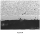
- Figure 1 is a photograph showing the microstructure of the cross section of the coating of the high-strength hot-stamped component according to Example 2.
- Table 1 lists the mass percentages of the various chemical elements in the substrates of the steel sheets for hot stamping in Examples 1-9 and the relationship between the chemical elements. Table 1 (wt%, the balance being Fe and unavoidable impurities) No. Chemical elements Nb+Mo+Ni C Si Mn Al Ti B Cr Nb Mo Ni Ex. 1 0.35 0.20 1.2 0.05 0.01 0.002 0.2 0.04 0.18 0.08 0.3 Ex. 2 0.22 0.1 1.0 0.01 0.03 0.0005 0.1 0.0001 0.2 0.1 0.3001 Ex. 3 0.25 0.23 1.19 0.1 0.03 0.001 0.2 0.005 0.25 0.2 0.455 Ex. 4 0.30 0.36 2.0 0.07 0.05 0.003 0.3 0.01 0.1 0.2 0.31 Ex.
- the hot stamped steel sheet could be an uncoated steel sheet or a coated steel sheet.
- the hot stamped steel sheet could specifically be: aluminum-silicon coated steel sheet, aluminum-silicon-zinc-magnesium coated steel sheet, aluminum-silicon-magnesium coated steel sheet, hot-dip galvanized steel sheet, or zinc-iron alloy coated steel sheet.
- Table 2-1 and Table 2-2 list the relevant process parameters of the method for manufacturing the high-strength hot-stamped components of Examples 1-9.
- Step (3) Step (4) Transfer time (s) Stamping speed (mm/s) Pressure hold time (s) Mold temperature during stamping (°C) Soaking temperature (°C) Soaking time (min) Ex. 1 15 40 10 100 200 20 Ex.
- the heat treatment temperatures for the heat treatment process in step (3) in Examples 1-9 are all numerical ranges rather than single-point values. This is because the heat treatment furnace is usually characterized by segmented control. The temperature of each segment can be controlled separately, and the temperature of each segment can be different from that of another segment. The range of the heat treatment temperature described in the present disclosure depends on the distribution range of all temperatures in all segments.
- Table 4 lists the relevant performance testing results of the high-strength hot-stamped component samples of Examples 1-9.
- Table 4 No. Strength-elongation product (GPa ⁇ %) Tensile strength (MPa) Elongation after fracture (%) Cold bending angle (°) Maximum three-point bending load (KN)* Drop hammer testing * Hydrogen content testing (ppm) Ex. 1 10.8 1700 6.4 65 15 No cracking 0.05 Ex. 2 10 1500 6.7 60 / / 0.01 Ex. 3 10.1 1600 6.3 60 / / 0.02 Ex. 4 11.4 1900 6 70 18 No cracking 0.03 Ex. 5 11 2000 5.5 75 17 No cracking 0.04 Ex. 6 10.6 1850 5.7 60 14 No cracking 0.05 Ex.
- Example 2 was a tailor welded component and Example 3 was a patch welded component, they both involved weld seams. Due to the influence of the weld seams, it's not appropriate to use the drop hammer testing for evaluation. At the same time, due to the influence of the weld seams, it's also not appropriate to use the maximum load testing for evaluation. Therefore, Examples 2 and 3 were not subjected to three-point bending testing or drop hammer testing.
- the high-strength hot-stamped components of Examples 1-9 exhibited high strength as well as excellent toughness and cold bending performance.
- the strength-elongation product of the high-strength hot-stamped components of Examples 1-9 was 10-12 GPa ⁇ %; the cold bending angle was 60-75 degrees; and the maximum three-point bending load was 13-20 KN.
- Figure 1 is a photograph showing the microstructure of the cross section of the coating of the high-strength hot-stamped component according to Example 2.
- Example 2 had an aluminum-silicon coating layer, including a substrate A and a coating layer B. There was an apparent interface layer C between the coating layer A and the substrate B.
Landscapes
- Chemical & Material Sciences (AREA)
- Engineering & Computer Science (AREA)
- Mechanical Engineering (AREA)
- Materials Engineering (AREA)
- Metallurgy (AREA)
- Organic Chemistry (AREA)
- Thermal Sciences (AREA)
- Physics & Mathematics (AREA)
- Crystallography & Structural Chemistry (AREA)
- Chemical Kinetics & Catalysis (AREA)
- Oil, Petroleum & Natural Gas (AREA)
- Heat Treatment Of Articles (AREA)
- Heat Treatment Of Sheet Steel (AREA)
- Shaping Metal By Deep-Drawing, Or The Like (AREA)
Abstract
Description
- The present disclosure relates to a method for manufacturing a high-strength component, and in particular to a hot-stamped component with high cold-bending performance and high strength, and a method for manufacturing the same.
- In recent years, along with the rapid development of the automotive industry, the market and users impose higher and higher requirements on vehicles, and lightweighting has gradually become a development trend of the automotive industry in the future.
- Nowadays, in order to meet the requirement with respect to vehicle lightweighting, hot stamped steel is often used to make automotive structural parts and safety parts. Hot stamped steel can both achieve vehicle lightweighting and improve vehicle safety. 1500 MPa grade hot stamped steel has been widely used in the automotive industry, and 1800 MPa hot stamped steel and 2000 MPa hot stamped steel have also been put into use one after another.
- However, research has revealed that the higher the strength of hot stamped steel having a fully martensitic structure, the lower the toughness of the steel, and the higher the risk of brittle fracture during collision and delayed cracking during service. This problem directly leads to the fact that it is difficult for current hot stamped steel to acquire both high strength and good toughness.
- In order to solve this problem, a large number of scientific and technological workers have made many beneficial attempts in recent years:
- Chinese Patent Publication
CN110799659A, published on February 14, 2020 and titled "METHOD FOR PRODUCING HIGH-STRENGTH STEEL COMPONENT WITH IMPROVED DUCTILITY AND COMPONENT OBTAINED BY SAME", discloses a method for producing a high-strength steel component with improved ductility and a component made by the method, which method mainly controls the Ni content and its distribution, and controls the Ni content in the matrix to be higher than 0.25% to obtain a high-strength steel component with good ductility. - Chinese Patent Publication
CN106399837A, published on February 15, 2017 and titled "STEEL FOR HOT STAMPING, HOT STAMPING PROCESS AND HOT-STAMPED MEMBER", discloses a fine-grained hot stamping steel. According to the technical solution disclosed thereby, the fine-grained steel for hot stamping is obtained mainly by adding V element to the matrix. It also discloses the hot stamping process. During the hot stamping process in this technical solution, it is necessary to control the mold surface temperature to be 200°C or less, and control the cooling rate of the steel in the mold to be no less than 10°C/s. - Chinese Patent Publication
CN111876676A, published on November 3, 2020 and titled "METHOD FOR PRODUCING 1800MPA-GRADE COLD-ROLLED STEEL FOR HOT STAMPING", discloses a method for producing a 1800MPa-grade cold-rolled steel for hot stamping. According to the technical solution disclosed thereby, a 1800MPa-grade hot stamped steel is obtained under the conditions that the cost is controlled at a low level, and no trace element is added. However, the toughness of the hot stamped steel, especially the cold bending performance, is insufficient. - Chinese Patent Publication
CN101583486A, published on November 18, 2009 and titled "COATED STEEL STRIP, METHOD FOR PREPARING SAME, METHOD FOR USING SAME, STAMPING BLANK PREPARED THEREFROM, STAMPED PRODUCT PREPARED THEREFROM AND ARTICLE CONTAINING SUCH STAMPED PRODUCT", reports a method for hot stamping a coated steel, which method limits the duration from the point when the blank exits the heat treatment furnace to the start of stamping to no more than 10 seconds, and controls the cooling rate of the blank to be greater than 50°C/s during the time from the point when the blank exits the furnace to the point when its temperature reaches 400°C. However, the technical solution does not involve any study on the toughness of the material. - Chinese Patent Publication
CN108588612A, published on September 28, 2018 and titled "HOT-STAMPED MEMBER, PRE-COATED STEEL SHEET FOR HOT STAMPING AND HOT STAMPING PROCESS", discloses a pre-coated hot stamped steel and a method for hot stamping the same. In the technical solution disclosed thereby, it's mentioned that the temperature of the steel sheet is 550°C or higher when it's transferred to the mold and it comes to the problem of low cold bending performance existing in Chinese PatentCN101583486B . According to this patent application, the cold bending problem is alleviated by reducing the coating thickness. - As it can be seen, in the current prior art, little research has been done by those skilled in the art on high-strength hot stamped steel with good cold bending performance. Among the above patent applications, only Chinese Patent Publication
CN110799659A involves study on the cold bending performance of the material while it's guaranteed that the hot stamped steel has high strength. - Research has revealed that the larger the cold bending angle of hot stamped steel, the more energy it can absorb under the same conditions. Thus, the fracture failure time can be postponed. Therefore, the present inventors believe that it is particularly important to study the cold bending performance of high-strength hot stamped steel and a feasible method for producing the same. In view of the above, the present disclosure is intended to provide a method for producing a high-strength hot-stamped component having high cold bending performance.
- One of the objects of the present disclosure is to provide a method for producing a high-strength hot-stamped component having high cold bending performance. The method is simple and feasible, and can effectively produce a high-strength hot-stamped component having high cold bending performance. It has good promotion prospects and application effects.
- In order to achieve the above object, the present disclosure provides a method for producing a high-strength hot-stamped component having high cold bending performance, comprising:
- (1) Manufacture of a steel sheet for hot stamping;
- (2) Component pre-processing;
- (3) Heat treatment, transfer and stamping of the component: Placing a semi-finished component processed into a specified shape in a heat treatment furnace, and controlling a heat treatment temperature to be 750-960°C and a total heat treatment time to be 1.5-10 min, wherein a period of time during which the heat treatment temperature is 880°C or higher is no less than 1.2 min; transferring the semi-finished component that has experienced the heat treatment to a mold, closing the mold and performing stamping, wherein the semi-finished component has a temperature of ≥900°C when it exits the heat treatment furnace; wherein if a steel sheet thickness of the component thus obtained is ≤1.5 mm, a transfer time is controlled to be 11-20 s, and if the steel sheet thickness of the component thus obtained is >1.5 mm, the transfer time is controlled to be 13-25 s;
- (4) Post-stamping processing: Homogenizing the component by soaking, followed by mechanical processing to obtain the finished product.
- The present inventors have optimized the design of the heat treatment, transfer and stamping process of the component in step (3) in the above technical solution of the present disclosure. Heat treatment, transfer and stamping are particularly important to the performances of the component described in the present disclosure. These three elements are complementary to each other. The heat treatment process is very critical to the forming of the component; the transfer is very critical to the cold bending and strength of the component; and the stamping is very important to the forming and strength of the component.
- The temperature and time of the heat treatment process may be adjusted flexibly according to the thickness specification and size of the component, mainly to guarantee complete austenitization and surface characteristics. The optimized transfer process is the core of the technical solution of the present disclosure. In the past, in order to guarantee high strength of a hot-formed component, the transfer process was required to be as fast as possible, and it was basically completed within 10 seconds. However, the present inventors have discovered by research that the transfer time can be controlled within an appropriate range in light of the turning point of the phase transition temperature of the substrate of the steel sheet for hot stamping, thereby ensuring high strength and improving the cold bending performance.
- In the specific implementation of the present disclosure, the heat treatment temperature within the above-mentioned temperature range of 750-960°C may include different temperature sections at different stages, or it may be just a temperature range at a single stage. The heat treatment temperature may increase or decrease freely, or may be a combination thereof. The total heat treatment time needs to be controlled between 1.5 minutes and 10 minutes, and the heat treatment temperature is controlled to be 880°C or higher for no less than 1.2 minutes. The temperature of the semi-finished product leaving the heat treatment furnace is ≥900°C (e.g., between 900 and 960°C); otherwise, incomplete austenitization will be resulted, thereby affecting the strength-elongation product. The heat treatment time refers to the total time at all heat treatment temperatures.
- Accordingly, in step (4) described in the present disclosure, the post-stamping processing can further eliminate the residual stress generated in the forming process, solve the problems of uneven structure and hydrogen diffusion, and thus further improve the cold bending performance of the component.
- In the present disclosure, the manufacture of step (1) may be implemented with a conventional manufacturing process in the art. For example, it includes steelmaking, hot rolling, cold rolling, annealing and other process steps to obtain a substrate strip steel according to the required elements. The resulting substrate strip steel may be used directly as a steel sheet for hot stamping, or the substrate strip steel may be further plated and then used as a steel sheet for hot stamping. The plated coating may be an aluminum-silicon coating, an aluminum-silicon-zinc-magnesium coating, an aluminum-silicon-magnesium coating, a zinc coating or a zinc-iron alloy coating. Steel sheets having the above-mentioned various types of coatings plated on the surfaces of the substrate steel strips may be formed by methods well known in the art.
- For example, a steel sheet having an aluminum-silicon coating on its surface is prepared by immersing a substrate strip steel into a plating solution containing 7-10% by mass of Si, 2-4% by mass of Fe, and a balance of Al and unavoidable impurities at 630-680°C. A steel sheet having a zinc-iron alloy coating on its surface is prepared by immersing a substrate strip steel into a plating solution containing 8-12% by mass of Zn, 2-4% by mass of Fe, and a balance of Al and unavoidable impurities at 420-700° C. A steel sheet having an aluminum-silicon-magnesium coating on its surface is prepared by immersing a substrate strip steel into a plating solution containing 6-10% by mass of Si, 0.5-3% by mass of Mg, and a balance of Al and unavoidable impurities at 630-700° C. A steel sheet having a zinc coating on its surface is prepared by immersing a substrate strip steel into a plating solution containing 0.08-0.3% by mass of Al and a balance of Zn and unavoidable impurities at 420-700° C. A steel sheet having an aluminum-silicon-zinc-magnesium coating on its surface is prepared by immersing a substrate strip steel into a plating solution containing 6-10% by mass of Si, 0.5-2% by mass of Mg, 8-12% by mass of Zn, and a balance of Al and unavoidable impurities at 420-700° C.
- In the present disclosure, the component pre-processing in step (2) provides the component with a desired shape. Depending on the desired shape of the component, the component is provided with the desired shape by one-step or multi-step laser processing or shearing, or by combining two or more steel sheets of different shapes and different thicknesses through tailor welding, patch welding or the like to complete the component pre-processing. Of course, the component pre-processing process described in the present disclosure is not limited to the operations stated herein, and in some other embodiments, it may further include similar or equivalent operations.
- In addition, it should be noted that if a tailor-welded component or a patch-welded component is obtained in step (2), and if one thickness is 1.5 mm or less and another thickness is 1.5 mm or more, both thicknesses need to be taken into account to determine the transfer time of the component. For example, 13 to 20 seconds may be selected.
- Further, in the method for producing a high-strength hot-stamped component having high cold bending performance according to the present disclosure, the steel sheet for hot stamping includes at least one of uncoated steel sheet, aluminum-silicon coated steel sheet, aluminum-silicon-zinc-magnesium coated steel sheet, aluminum-silicon-magnesium coated steel sheet, hot-dip galvanized steel sheet, and zinc-iron alloy coated steel sheet.
- Further, in the method for producing a high-strength hot-stamped component having high cold bending performance according to the present disclosure, the chemical composition of the substrate of the steel sheet for hot stamping is: C: 0.2-0.4%, Mn: 1.0-2.0%, Si: 0.1-0.5%, Al: 0.01-0.1%, Ti: 0.01-0.1%, B: 0.0005-0.01%, Cr: 0.1-0.5%, and Nb+Mo+Ni: 0.3-0.6%, based on mass percentage, wherein the mass percentage of any one of Nb, Mo, and Ni does not exceed 0.3%.
- In the substrate of the steel sheet for hot stamping according to the present disclosure, the chemical elements are designed according to the following principles:
- C: In the present disclosure, the addition of an appropriate amount of C element into the substrate can guarantee the strength of the steel, so as to guarantee the strength of the hot-stamped component. Therefore, the content of C element in the steel should not be too low. If the content of C element in the steel is lower than 0.2%, the strength cannot be guaranteed. At the same time, the content of C element in the steel should not be too high. If the content of C element in the steel is higher than 0.4%, the strength will be too high, such that the welding performance of the steel will be degraded. Hence, with the performance of the substrate taken into account, the mass percentage of C element in the substrate of the present disclosure is controlled at 0.2-0.4%.
- Mn: In the substrate of the present disclosure, like C element, Mn element is also added to guarantee the strength of the hot-stamped component. Meanwhile, Mn element can further make up the toughness of the substrate steel. If the content of Mn element in the steel is lower than 1.0%, the strength of the steel cannot be guaranteed; if the content of Mn element in the steel is higher than 2.0%, both element segregation and production cost will increase. Hence, in order to exploit the beneficial effect of Mn element, the mass percentage of Mn element in the substrate of the present disclosure is controlled at 1.0% - 2.0%.
- Si: In the present disclosure, the addition of an appropriate amount of Si element into the substrate can increase the strength of the hot-stamped component, and it's also an important deoxygenation agent in the steelmaking process. If the content of Si element in the steel is too high, severe oxidation will occur during the production process, making it difficult to guarantee good product surface quality. Therefore, in the substrate of the present disclosure, the mass percentage of Si element is controlled at 0.1 - 0.5%.
- Al: In the substrate of the present disclosure, Al element is also a deoxygenation agent. The addition of an appropriate amount of Al element can also improve the impact toughness of the steel. Therefore, with the influence of Al element on the performances of the steel taken into account, the mass percentage of Al element in the substrate of the present disclosure is controlled at 0.01-0.1%.
- B: The addition of an appropriate amount of B element into the substrate of the present disclosure can improve the hardenability of the steel to ensure that the hot-stamped component is fully hardened everywhere. Therefore, in the substrate of the present disclosure, the mass percentage of B element is controlled at 0.0005 - 0.01%.
- Ti: In the substrate of the present disclosure, Ti is a strengthening element of C and N. The addition of an appropriate amount of Ti element into the steel can improve the strength and toughness of the substrate, thereby further improving the strength and toughness of the hot-stamped component. At the same time, Ti element can also interact with B element, so that better use of B can be made to improve hardenability. Hence, in order to exploit the beneficial effect of Ti element, the mass percentage of Ti element in the substrate of the present disclosure is controlled at 0.01 - 0.1%.
- Cr: The addition of an appropriate amount of Cr element into the substrate of the present disclosure can also improve the hardenability of the steel, and ensure that the hot-stamped component is fully hardened everywhere. Therefore, in the substrate of the present disclosure, the mass percentage of Cr element is controlled at 0.1 - 0.5%.
- It should be noted that, appropriate amounts of Nb, Mo, and Ni elements are further added into the substrate of the present disclosure. Nb and Mo elements can both play a role in refining grains and improving the toughness of the hot-stamped component. Ni element can also play a role in improving the toughness of the hot-stamped component, and Ni also promotes hydrogen diffusion. Therefore, in the substrate of the present disclosure, the mass percentage of Nb, Mo, and Ni elements is controlled to meet: Nb+Mo+Ni: 0.3-0.6%. The mass percentage of any one of Nb, Mo and Ni does not exceed 0.3%. In some embodiments, the mass percentage of Nb is 0.0001% - 0.25%. In some embodiments, the mass percentage of Mo is 0.1% - 0.25%. In some embodiments, the mass percentage of Ni is 0.05% - 0.25%, such as 0.08% - 0.2%.
- Further, in the method for producing a high-strength hot-stamped component having high cold bending performance according to the present disclosure, in step (3), the total heat treatment time is controlled to be 1.5 - 8 minutes.
- Further, in the method for producing a high-strength hot-stamped component having high cold bending performance according to the present disclosure, in step (3), the stamping speed is controlled to be 40 - 80 mm/s, and held for 2 - 30 seconds.
- Further, in the method for producing a high-strength hot-stamped component having high cold bending performance according to the present disclosure, in step (3), the mold temperature is always lower than 200° C during the stamping process. In some embodiments, during the stamping process, the mold temperature is in the range of 25-190°C.
- Further, in the method for producing a high-strength hot-stamped component having high cold bending performance according to the present disclosure, in step (4), homogenization by soaking is performed at a temperature of 150-250°C for 10-30 minutes.
- Further, in the method for producing a high-strength hot-stamped component having high cold bending performance according to the present disclosure, in step (4), the mechanical processing includes at least one of cutting, trimming, punching, and welding.
- Further, in the method for producing a high-strength hot-stamped component having high cold bending performance according to the present disclosure, in step (3), a martensitic structure is formed in the component at a volume ratio of 95% or higher.
- The method of the present disclosure can be used to prepare a high-strength hot-stamped component having high cold bending performance with a strength-elongation product of ≥10 GPa·% and a cold bending angle of ≥60 degrees. Preferably, the maximum three-point bending load of the high-strength hot-stamped component is ≥13KN. In some embodiments, the high-strength hot-stamped component prepared according to the method of the present disclosure has a tensile strength of ≥1500 MPa and an elongation after fracture of ≥5.5%. In some embodiments, the high-strength hot-stamped component prepared according to the method of the present disclosure has a tensile strength of 1500-1700 MPa, an elongation after fracture of 6.0-7.0%, and a strength-elongation product of ≥10 GPa·%. In some embodiments, the high-strength hot-stamped component prepared according to the method of the present disclosure has a tensile strength of 1800 - 2100 MPa, an elongation after fracture of 5.5 - 6.0%, and a strength-elongation product of ≥10.5 GPa·%.
- Therefore, another object of the present disclosure is to provide a high-strength hot-stamped component. The high-strength hot-stamped component has both high strength and high cold bending performance. It has a wide range of applicability and can be effectively used in the automotive industry. It exhibits good resistance to head-on and side collisions during car collision.
- In order to achieve the above object, the present disclosure provides a high-strength hot-stamped component having a strength-elongation product of ≥10 GPa·%, and a cold bending angle of ≥60 degrees. In some embodiments, the maximum three-point bending load of the high-strength hot-stamped component is ≥13 KN. In some embodiments, the high-strength hot-stamped component of the present disclosure has a strength-elongation product of 10-12 GPa·%, a cold bending angle of 60-75 degrees, and a maximum three-point bending load of 13-20 KN. In some embodiments, the content of diffusible hydrogen in the high-strength hot-stamped component of the present disclosure is 0.01-0.06 ppm. In some embodiments, the high-strength hot-stamped component has a tensile strength of ≥1500 MPa and an elongation after fracture of ≥5.5%. In some embodiments, the high-strength hot-stamped component has a tensile strength of 1500-1700 MPa, an elongation after fracture of 6.0-7.0%, and a strength-elongation product of ≥10 GPa·%. In some embodiments, the high-strength hot-stamped component has a tensile strength of 1800 - 2100 MPa, an elongation after fracture of 5.5 - 6.0%, and a strength-elongation product of ≥10.5 GPa·%. In some embodiments, the hot-stamped component is made by the method described in any embodiment of the present disclosure.
- Compared with the prior art, the method for producing a high-strength hot-stamped component having high cold bending performance and the hot-stamped component according to the present disclosure have the following advantages and beneficial effects:
In the present disclosure, the present inventors have reasonably optimized the design of the method for manufacturing the high-strength hot-stamped component. By optimizing the control of the three processes of heat treatment, transfer and stamping, it can be ensured that the component has high strength while also having good toughness and cold bending performance. - In the method for producing the high-strength hot-stamped component having high cold bending performance according to the present disclosure, 95% or higher of martensitic structure is formed in the component during the heat treatment and stamping process, so that the component is able to acquire high strength. At the same time, during the precisely controlled transfer of the component, the present disclosure makes full use of the difference in cooling between the skin and the core, and a gradient control of structural transformation in the skin of the component is achieved. This is very helpful in improving the toughness and cold bending performance of the component.
- The performances of the high-strength hot-stamped component prepared by the above method of the present disclosure are quite excellent. It has a strength-elongation product of ≥10GPa·%, a cold bending angle of ≥60 degrees, and preferably a maximum three-point bending load of ≥13KN. The high-strength hot-stamped component has a wide range of applicability and can be effectively used in the automotive industry. It exhibits good resistance to head-on and side collisions during car collision.
-
Figure 1 is a photograph showing the microstructure of the cross section of the coating of the high-strength hot-stamped component according to Example 2. - The method for producing a high-strength hot-stamped component having high cold bending performance and the hot-stamped component according to the present disclosure will be further explained and illustrated with reference to the following specific examples. However, such explanation and illustration do not limit the technical solution of the present disclosure in any improper way.
- Table 1 lists the mass percentages of the various chemical elements in the substrates of the steel sheets for hot stamping in Examples 1-9 and the relationship between the chemical elements.
Table 1 (wt%, the balance being Fe and unavoidable impurities) No. Chemical elements Nb+Mo+Ni C Si Mn Al Ti B Cr Nb Mo Ni Ex. 1 0.35 0.20 1.2 0.05 0.01 0.002 0.2 0.04 0.18 0.08 0.3 Ex. 2 0.22 0.1 1.0 0.01 0.03 0.0005 0.1 0.0001 0.2 0.1 0.3001 Ex. 3 0.25 0.23 1.19 0.1 0.03 0.001 0.2 0.005 0.25 0.2 0.455 Ex. 4 0.30 0.36 2.0 0.07 0.05 0.003 0.3 0.01 0.1 0.2 0.31 Ex. 5 0.38 0.25 1.5 0.03 0.05 0.002 0.5 0.05 0.2 0.2 0.45 Ex. 6 0.35 0.40 1.30 0.05 0.09 0.004 0.3 0.1 0.25 0.2 0.55 Ex. 7 0.37 0.5 1.4 0.08 0.01 0.01 0.4 0.25 0.15 0.2 0.6 Ex. 8 0.30 0.30 1.70 0.08 0.03 0.005 0.3 0.05 0.24 0.2 0.49 Ex. 9 0.4 0.36 1.20 0.07 0.05 0.006 0.3 0.04 0.15 0.15 0.34 - In the present disclosure, the high-strength hot-stamped components of Examples 1-9 were each prepared by the following steps:
- (1) A substrate strip steel was manufactured by steelmaking, hot rolling, cold rolling, annealing and other process steps based on the mass percentages of the various chemical elements shown in Table 1. The resulting substrate strip steel could be used directly as a steel sheet for hot stamping, or the substrate strip steel could be further plated and then used as a steel sheet for hot stamping.
- (2) Component pre-processing: Depending on the desired component shape, blanking could be accomplished by one-step or multi-step laser processing or shearing, or by combining two or more steel sheets of different shapes and different thicknesses through tailor welding, patch welding, etc.
- (3) Heat treatment, transfer and stamping of the component: A semi-finished component processed into a specified shape was placed in a heat treatment furnace. The heat treatment temperature was controlled to be 750-960°C; the total heat treatment time was controlled to be 1.5-10 min, preferably 1.5-8 min; and the period of time during which the heat treatment temperature was 880°C or higher was no less than 1.2 min. The semi-finished component that had experienced the heat treatment was transferred to a mold. The mold was closed, and stamping was performed. The semi-finished component had a temperature of no less than 900°C when it exited the heat treatment furnace. The upper and lower parts of the mold were joined together with the use of a press. The stamping speed was controlled to be 40-80 mm/s, and held for 2-30 seconds. During the stamping process, the mold temperature was always below 200°C. If the steel sheet thickness of the resulting component was ≤1.5 mm, the transfer time was controlled to be 11-20 s, and if the steel sheet thickness of the resulting component was >1.5 mm, the transfer time was controlled to be 13-25 s.
- (4) Post-stamping processing: The component was soaked and homogenized. The temperature of homogenization by soaking was controlled to be 150-250°C for 10-30 minutes, and then mechanical processing was performed to obtain a finished product. The mechanical processing included cutting, trimming, punching, and welding.
- It should be noted that in step (1) of the above manufacturing method, the hot stamped steel sheet could be an uncoated steel sheet or a coated steel sheet. When the hot stamped steel sheet was a coated steel sheet, it could specifically be: aluminum-silicon coated steel sheet, aluminum-silicon-zinc-magnesium coated steel sheet, aluminum-silicon-magnesium coated steel sheet, hot-dip galvanized steel sheet, or zinc-iron alloy coated steel sheet.
- In the present disclosure, the specific process steps in the above steps (1) and (2) of Examples 1-9 are as follows:
- Example 1: A 1.2 mm substrate strip steel was obtained by steelmaking, hot rolling, cold rolling and annealing based on the mass percentages of the various chemical elements shown in Table 1. The 1.2 mm substrate strip steel was hot dipped with aluminum and silicon at 650°C to obtain an aluminum-silicon coated steel sheet, wherein the composition of the plating solution was 9% Si, 2.3% Fe, and a balance of Al and unavoidable impurities. In the component pre-processing step, the aluminum-silicon coated steel sheet was continuously blanked into a component of a certain shape.
- Example 2: A 1.5 mm substrate strip steel and a 1.8 mm substrate strip steel were obtained by steelmaking, hot rolling, cold rolling and annealing based on the mass percentages of the various chemical elements shown in Table 1. The 1.5 mm substrate strip steel and the 1.8 mm substrate strip steel were hot dipped with aluminum and silicon at 650°C to obtain aluminum-silicon coated steel sheets, wherein the composition of the plating solution was 9% Si, 2.3% Fe, and a balance of Al and unavoidable impurities. In the component pre-processing step, the aluminum-silicon coated steel sheets were laser blanked into components of a certain shape, and the two components were connected by tailor welding to obtain a component of a certain shape.
- Example 3: A 1.8 mm substrate strip steel was obtained by steelmaking, hot rolling, cold rolling and annealing based on the mass percentages of the various chemical elements shown in Table 1. The 1.8 mm substrate strip steel was hot dipped with aluminum and silicon at 660°C to obtain an aluminum-silicon coated steel sheet, wherein the composition of the plating solution was 8.5% Si, 2.5% Fe, and a balance of Al and unavoidable impurities. In the component pre-processing step, the aluminum-silicon coated steel sheet was continuously blanked into a billet of a certain shape, and a patch was made at a local position of the billet by spot welding (patch welding was performed with two 1.8 mm thick substrates) to obtain a component of a certain shape.
- Example 4: A 2.0 mm substrate strip steel was obtained by steelmaking, hot rolling, cold rolling and annealing based on the mass percentages of the various chemical elements shown in Table 1, and the substrate strip steel was used as a steel sheet for hot stamping. In the component pre-processing step, the steel sheet was continuously blanked into a billet of a certain shape.
- Example 5: A 2.3 mm substrate strip steel was obtained by steelmaking, hot rolling, cold rolling and annealing based on the mass percentages of the various chemical elements shown in Table 1, and the substrate strip steel was used as a steel sheet for hot stamping. In the component pre-processing step, the steel sheet was continuously blanked into a billet of a certain shape.
- Example 6: A 1.4 mm substrate strip steel was obtained by steelmaking, hot rolling, cold rolling and annealing based on the mass percentages of the various chemical elements shown in Table 1. The 1.4 mm substrate strip steel was subjected to hot-dip galvanization and alloying at 680°C to obtain a zinc-iron alloy coated steel sheet, wherein the composition of the plating solution was 9% Zn, 2.3% Fe, and a balance of Al and unavoidable impurities. In the component pre-processing step, the zinc-iron alloy coated steel sheet was laser blanked into a billet of a certain shape.
- Example 7: A 2.5 mm substrate strip steel was obtained by steelmaking, hot rolling, cold rolling and annealing based on the mass percentages of the various chemical elements shown in Table 1. The 2.5 mm substrate strip steel was hot dipped with aluminum, silicon and magnesium at 680°C to obtain an aluminum-silicon-magnesium coated steel sheet, wherein the composition of the plating solution was 8.5% Si, 1% Mg, and a balance of Al and unavoidable impurities. In the component pre-processing step, the aluminum-silicon-magnesium coated steel sheet was laser blanked into a billet of a certain shape.
- Example 8: A 0.9 mm substrate strip steel was obtained by steelmaking, hot rolling, cold rolling and annealing based on the mass percentages of the various chemical elements shown in Table 1. The 0.9 mm substrate strip steel was hot dipped at 680°C to obtain a hot-dip galvanized steel sheet, wherein the composition of the plating solution was 0.13% Al and a balance of Zn and unavoidable impurities. In the component pre-processing step, the hot-dip galvanized steel sheet was laser blanked into a billet of a certain shape.
- Example 9: A 3.0 mm substrate strip steel was obtained by steelmaking, hot rolling, cold rolling and annealing based on the mass percentages of the various chemical elements shown in Table 1. The 3.0 mm substrate strip steel was hot dipped at 680°C to obtain an aluminum-silicon-zinc-magnesium coated steel sheet, wherein the composition of the plating solution was 8.5% Si, 1% Mg, 10%Zn, and a balance of Al and unavoidable impurities. In the component pre-processing step, the aluminum-silicon-zinc-magnesium coated steel sheet was laser blanked into a billet of a certain shape, and the billet was heat treated.
- It should be noted that, in the present disclosure, the design of the chemical compositions of the hot stamped steel sheets for the high-strength hot-stamped components of Examples 1-9 and the related processes all meet the requirements of the design specification according to the present disclosure.
- Table 2-1 and Table 2-2 list the relevant process parameters of the method for manufacturing the high-strength hot-stamped components of Examples 1-9.
Table 2-1 No. Step (1) Step (2) Step (3) Strip steel thickness (mm) Coating Pre-processin 9 Heat treatment temperature (°C) Total heat treatment time (min) Time during which the heat treatment temperature is 880°C or higher (min) Temperature of the semi-finished product when it leaves the heat treatment furnace (°C) Ex. 1 1.2 Aluminum-silicon coating Blanking 780-930 3 1.5 900 Ex. 2 1.5, 1.8 Aluminum-silicon coating Blanking, tailor welding 800-940 4 2 940 Ex. 3 1.8 Aluminum-silicon coating Blanking, patch welding 850-950 5 4 950 Ex. 4 2.0 No coating Blanking 900-930 4 4 930 Ex. 5 2.3 No coating Blanking 900-960 5 5 950 Ex. 6 1.4 Zinc-iron alloy Blanking 900-930 3 3 920 Ex. 7 2.5 Aluminum-silicon-ma gnesium coating Blanking 800-930 6 5 930 Ex. 8 0.9 Hot-dip galvanized coating Blanking 780-900 1.5 1.2 900 Ex. 9 3.0 Aluminum-silicon-zin c-magnesi um coating Blanking 750-930 10 6 930 Table 2-2 No. Step (3) Step (4) Transfer time (s) Stamping speed (mm/s) Pressure hold time (s) Mold temperature during stamping (°C) Soaking temperature (°C) Soaking time (min) Ex. 1 15 40 10 100 200 20 Ex. 2 15 50 16 25 230 15 Ex. 3 20 60 15 150 250 20 Ex. 4 23 60 12 160 170 25 Ex. 5 20 80 10 190 220 20 Ex. 6 20 70 8 150 250 10 Ex. 7 18 60 15 160 200 15 Ex. 8 11 60 2 100 150 30 Ex. 9 25 50 30 160 200 20 - It should be made clear that in Table 2-1 in the present disclosure, the heat treatment temperatures for the heat treatment process in step (3) in Examples 1-9 are all numerical ranges rather than single-point values. This is because the heat treatment furnace is usually characterized by segmented control. The temperature of each segment can be controlled separately, and the temperature of each segment can be different from that of another segment. The range of the heat treatment temperature described in the present disclosure depends on the distribution range of all temperatures in all segments.
- In addition, it should be noted that when the above-mentioned manufacturing process was implemented in Examples 1 to 9, after the components of Examples 1 to 9 were heat treated, transferred and stamped according to the design requirements in step (3), the components of Examples 1 to 9 could be sampled, and the microstructure of the component of each Example could be examined to obtain the volume ratio of martensitic structure in each component of Examples 1 to 9. The relevant test results are listed in Table 3 below. The percentage of martensite in a component was measured by metallography: after the sample was mounted, it was mechanically ground, polished and etched, and the collected image was processed by a metallographic image analysis software to obtain the percentage of martensitic structure.
Table 3 No. Volume ratio of martensitic structure (%) Ex. 1 95 Ex. 2 96 Ex. 3 97 Ex. 4 95 Ex. 5 97 Ex. 6 98 Ex. 7 96 Ex. 8 99 Ex. 9 96 - As the finished products of Examples 1-9 finally obtained through the above process steps, the high-strength hot-stamped components were each sampled, and various performances were tested on the sample of each Example. The results of the performance testing are listed in Table 4 below.
- The performance testing processes used in the present disclosure are as follows:
- (1) Strength-elongation product: Strength-elongation product is a comprehensive performance indicator that characterizes the level of strength and toughness of a metal material. The product of tensile strength and elongation after fracture of a component is used in the present disclosure to provide the strength-elongation product of the sample of each Example. The tensile strength and elongation after fracture of the component were obtained through the tensile testing according to
GB/T228.1 - (2) Cold bending testing: Cold bending testing was performed according to Standard VDA-238 to obtain the cold bending angles of the samples of Examples 1-9. A larger cold bending angle indicates better toughness of a material; and a smaller cold bending angle indicates lower toughness of a material.
- (3) Three-point bending testing and drop hammer testing: Three-point bending testing and drop hammer testing were performed by placing the hot-stamped component of an Example on a bending device, adjusting the span, and applying a load to the component for bending testing until the component fractured. The maximum load at which the component fractured was recorded. In the drop hammer testing, a 30 kg drop hammer was allowed to drop from a height of 50 cm in the form of free fall, and the cracking of the sample component of each Example was observed.
- (4) Measurement of diffusible hydrogen content: A sample was obtained from a component by wire cutting, punching or sawing with water cooling, and ultrasonically cleaned with acetone. The diffusible hydrogen content in the sample of each Example was measured at 300-400°C using a hydrogen analyzer.
- Table 4 lists the relevant performance testing results of the high-strength hot-stamped component samples of Examples 1-9.
Table 4 No. Strength-elongation product (GPa·%) Tensile strength (MPa) Elongation after fracture (%) Cold bending angle (°) Maximum three-point bending load (KN)* Drop hammer testing * Hydrogen content testing (ppm) Ex. 1 10.8 1700 6.4 65 15 No cracking 0.05 Ex. 2 10 1500 6.7 60 / / 0.01 Ex. 3 10.1 1600 6.3 60 / / 0.02 Ex. 4 11.4 1900 6 70 18 No cracking 0.03 Ex. 5 11 2000 5.5 75 17 No cracking 0.04 Ex. 6 10.6 1850 5.7 60 14 No cracking 0.05 Ex. 7 12 2100 5.7 60 20 No cracking 0.06 Ex. 8 10.5 1700 6.2 60 13 No cracking 0.03 Ex. 9 11.8 2000 5.9 60 15 No cracking 0.04 Note: * indicates that the drop hammer testing was conducted using the high-strength hot-stamped components of Examples 1-9 as anti-collision beam parts. - It should be noted that, since Example 2 was a tailor welded component and Example 3 was a patch welded component, they both involved weld seams. Due to the influence of the weld seams, it's not appropriate to use the drop hammer testing for evaluation. At the same time, due to the influence of the weld seams, it's also not appropriate to use the maximum load testing for evaluation. Therefore, Examples 2 and 3 were not subjected to three-point bending testing or drop hammer testing.
- It can be seen from Table 4 that the high-strength hot-stamped components of Examples 1-9 exhibited high strength as well as excellent toughness and cold bending performance. In the present disclosure, the strength-elongation product of the high-strength hot-stamped components of Examples 1-9 was 10-12 GPa·%; the cold bending angle was 60-75 degrees; and the maximum three-point bending load was 13-20 KN.
- Accordingly, as further shown by Table 4, when the high-strength hot-stamped components of Examples 1-9 as anti-collision beam components were subjected to drop hammer testing, none of the high-strength hot-stamped components of Examples 1-9 cracked, indicating excellent strength-elongation product and toughness. At the same time, the diffusible hydrogen content of the high-strength hot-stamped components of Examples 1-9 was 0.01 - 0.06 ppm, indicating good resistance to hydrogen embrittlement.
-
Figure 1 is a photograph showing the microstructure of the cross section of the coating of the high-strength hot-stamped component according to Example 2. - As shown by
Figure 1 , in the high-strength hot-stamped component of Example 2, Example 2 had an aluminum-silicon coating layer, including a substrate A and a coating layer B. There was an apparent interface layer C between the coating layer A and the substrate B. - It should be noted that the combinations of the various technical features in the present case are not limited to the combinations described in the claims in the present case or the combinations described in the specific Examples. All technical features recorded in the present case can be combined freely in any way unless a contradiction is incurred.
- It should also be noted that the Examples listed above are only specific embodiments of the present disclosure. Obviously, the present disclosure is not limited to the above Examples. Variations or modifications made based on them can be directly derived or easily conceived of from the present disclosure by those skilled in the art, and they should all fall within the protection scope of the present disclosure.
Claims (15)
- A method for producing a high-strength hot-stamped component having high cold bending performance, comprising:(1) Manufacturing a steel sheet for hot stamping;(2) Component pre-processing;(3) Heat treatment, transfer and stamping of the component: Placing a semi-finished component processed into a specified shape in a heat treatment furnace, and controlling a heat treatment temperature to be 750-960°C and a total heat treatment time to be 1.5-10 min, wherein a period of time during which the heat treatment temperature is 880°C or higher is no less than 1.2 min; transferring the semi-finished component that has experienced the heat treatment to a mold, closing the mold and performing stamping, wherein the semi-finished component has a temperature of ≥900°C when it exits the heat treatment furnace; wherein if a steel sheet thickness of the component thus obtained is ≤1.5 mm, a transfer time is controlled to be 11-20 s, and if the steel sheet thickness of the component thus obtained is >1.5 mm, the transfer time is controlled to be 13-25 s;(4) Post-stamping processing: Homogenizing the component by soaking, followed by mechanical processing to obtain the finished product.
- The method for producing a high-strength hot-stamped component having high cold bending performance according to claim 1, wherein the steel sheet for hot stamping includes at least one of uncoated steel sheet, aluminum-silicon coated steel sheet, aluminum-silicon-zinc-magnesium coated steel sheet, aluminum-silicon-magnesium coated steel sheet, hot-dip galvanized steel sheet, and zinc-iron alloy coated steel sheet.
- The method for producing a high-strength hot-stamped component having high cold bending performance according to claim 1, wherein a chemical composition of a substrate of the steel sheet for hot stamping is: C: 0.2-0.4%, Mn: 1.0-2.0%, Si: 0.1-0.5%, Al: 0.01-0.1%, Ti: 0.01-0.1%, B: 0.0005-0.01%, Cr: 0.1-0.5%, and Nb+Mo+Ni: 0.3-0.6%, based on mass percentage, wherein the mass percentage of any one of Nb, Mo, and Ni does not exceed 0.3%; preferably, a mass percentage of Nb is 0.0001% - 0.25%; a mass percentage of Mo is 0.1% - 0.25%; a mass percentage of Ni is 0.05% - 0.25%, such as 0.08% - 0.2%.
- The method for producing a high-strength hot-stamped component having high cold bending performance according to claim 1, wherein in step (3), the total heat treatment time is controlled to be 1.5 - 8 minutes.
- The method for producing a high-strength hot-stamped component having high cold bending performance according to claim 1, wherein in step (3), a stamping speed is controlled to be 40 - 80 mm/s, and held for 2 - 30 seconds.
- The method for producing a high-strength hot-stamped component having high cold bending performance according to claim 1 or 5, wherein in step (3), a mold temperature is always lower than 200°C during the stamping.
- The method for producing a high-strength hot-stamped component having high cold bending performance according to claim 1, wherein in step (4), homogenization by soaking is performed at a temperature of 150-250°C for 10-30 minutes.
- The method for producing a high-strength hot-stamped component having high cold bending performance according to claim 1, wherein in step (4), the mechanical processing includes at least one of cutting, trimming, punching, and welding.
- The method for producing a high-strength hot-stamped component having high cold bending performance according to claim 1, wherein in step (3), a martensitic structure is formed in the component at a volume ratio of 95% or higher.
- The method for producing a high-strength hot-stamped component having high cold bending performance according to claim 1, wherein the hot-stamped component has a strength-elongation product of ≥10 GPa·% and a cold bending angle of ≥60 degrees; preferably, the hot-stamped component has a maximum three-point bending load of ≥13KN; preferably, the hot-stamped component has a tensile strength of ≥1500 MPa; and preferably, the hot-stamped component has an elongation after fracture of ≥5.5%.
- A hot-stamped component manufactured according to the method of any one of claims 1-10.
- A hot-stamped component, wherein a chemical composition of a substrate of the hot-stamped component is: C: 0.2-0.4%, Mn: 1.0-2.0%, Si: 0.1-0.5%, Al: 0.01-0.1%, Ti: 0.01-0.1%, B: 0.0005-0.01%, Cr: 0.1-0.5%, and Nb+Mo+Ni: 0.3-0.6%, based on mass percentage, wherein the mass percentage of any one of Nb, Mo, and Ni does not exceed 0.3%, wherein the hot-stamped component has a strength-elongation product of ≥10 GPa·% and a cold bending angle of ≥60 degrees.
- The hot-stamped component according to claim 12, wherein a mass percentage of Nb is 0.0001% - 0.25%; a mass percentage of Mo is 0.1% - 0.25%; and a mass percentage of Ni is 0.05% - 0.25%, such as 0.08% - 0.2%.
- The hot-stamped component according to claim 12 or 13, wherein the hot-stamped component further has a coating on its surface; preferably, the coating is selected from aluminum-silicon coating, aluminum-silicon-zinc-magnesium coating, aluminum-silicon-magnesium coating, hot-dip galvanized coating and zinc-iron alloy coating.
- The hot-stamped component according to claim 12, 13 or 14, wherein the hot-stamped component has a maximum three-point bending load of ≥13 KN; and/or the hot-stamped component has a diffusible hydrogen content of 0.01-0.06 ppm; and/or the hot-stamped component has a tensile strength of ≥1500 MPa; and/or the hot-stamped component has an elongation after fracture of ≥5.5%.
Applications Claiming Priority (2)
| Application Number | Priority Date | Filing Date | Title |
|---|---|---|---|
| CN202210311710.0A CN116851528B (en) | 2022-03-28 | 2022-03-28 | Method for producing high-strength hot-stamped parts with high cold bending performance; hot-stamped parts |
| PCT/CN2023/084138 WO2023185754A1 (en) | 2022-03-28 | 2023-03-27 | Hot-stamped component having high cold-bending performance and high strength, and manufacturing method therefor |
Publications (2)
| Publication Number | Publication Date |
|---|---|
| EP4502224A1 true EP4502224A1 (en) | 2025-02-05 |
| EP4502224A4 EP4502224A4 (en) | 2025-08-27 |
Family
ID=88199153
Family Applications (1)
| Application Number | Title | Priority Date | Filing Date |
|---|---|---|---|
| EP23778119.0A Pending EP4502224A4 (en) | 2022-03-28 | 2023-03-27 | Hot-stamped component with high cold bending performance and high strength, and manufacturing process therefor |
Country Status (9)
| Country | Link |
|---|---|
| US (1) | US20250215519A1 (en) |
| EP (1) | EP4502224A4 (en) |
| JP (1) | JP2025512864A (en) |
| CN (1) | CN116851528B (en) |
| AU (1) | AU2023247884A1 (en) |
| IL (1) | IL315858A (en) |
| MX (1) | MX2024011766A (en) |
| WO (1) | WO2023185754A1 (en) |
| ZA (1) | ZA202408081B (en) |
Family Cites Families (29)
| Publication number | Priority date | Publication date | Assignee | Title |
|---|---|---|---|---|
| HUE036195T2 (en) | 2006-10-30 | 2018-06-28 | Arcelormittal | Coated steel strips, processes for their preparation, processes for their application, blank pieces thereof, extruded products therefor, and finished products containing such extruded products |
| WO2009090443A1 (en) * | 2008-01-15 | 2009-07-23 | Arcelormittal France | Process for manufacturing stamped products, and stamped products prepared from the same |
| US20090242086A1 (en) * | 2008-03-31 | 2009-10-01 | Honda Motor Co., Ltd. | Microstructural optimization of automotive structures |
| KR20130132623A (en) * | 2011-04-01 | 2013-12-04 | 신닛테츠스미킨 카부시키카이샤 | Hot stamp-molded high-strength component having excellent corrosion resistance after coating, and method for manufacturing same |
| KR101271802B1 (en) * | 2011-08-17 | 2013-06-07 | 주식회사 포스코 | Manufacturing method for hot press formed material having less crack |
| EP2664682A1 (en) * | 2012-05-16 | 2013-11-20 | ThyssenKrupp Steel Europe AG | Steel for the production of a steel component, flat steel product comprising same, component comprised of same and method for producing same |
| KR101318060B1 (en) * | 2013-05-09 | 2013-10-15 | 현대제철 주식회사 | Hot stamping product with advanced toughness and method of manufacturing the same |
| CN104384283A (en) * | 2014-09-25 | 2015-03-04 | 中南林业科技大学 | Hot-stamping forming process of 22MnB5 high-strength thin steel plate |
| CN104846274B (en) * | 2015-02-16 | 2017-07-28 | 重庆哈工易成形钢铁科技有限公司 | Hot press-formed use steel plate, hot press-formed technique and hot press-formed component |
| KR101770031B1 (en) * | 2015-09-23 | 2017-08-21 | 현대제철 주식회사 | Manufacturing method for molded articles |
| WO2017144419A1 (en) * | 2016-02-23 | 2017-08-31 | Tata Steel Ijmuiden B.V. | Hot formed part and method for producing it |
| CN106399837B (en) | 2016-07-08 | 2018-03-13 | 东北大学 | Hot press-formed steel, hot press-formed technique and hot press-formed component |
| CN106191673B (en) * | 2016-07-25 | 2017-12-29 | 江阴兴澄特种钢铁有限公司 | The steel plate of a kind of cold-bending property excellent yield strength more than 1100MPa and preparation method thereof |
| EP3548641B1 (en) * | 2016-11-29 | 2020-08-26 | Tata Steel IJmuiden B.V. | Method for manufacturing a hot-formed article, and obtained article |
| WO2018220412A1 (en) | 2017-06-01 | 2018-12-06 | Arcelormittal | Method for producing high-strength steel parts with improved ductility, and parts obtained by said method |
| CN108396224A (en) * | 2018-04-03 | 2018-08-14 | 河钢股份有限公司承德分公司 | A kind of hot press-formed ultra-thin hot-rolled strip steel and its production method |
| CN108588612B (en) | 2018-04-28 | 2019-09-20 | 育材堂(苏州)材料科技有限公司 | Hot stamping components, pre-coated steel sheets for hot stamping and hot stamping process |
| CN117483561A (en) * | 2018-08-08 | 2024-02-02 | 宝山钢铁股份有限公司 | Method for manufacturing hot-stamped component with aluminum-silicon alloy coating and hot-stamped component |
| CN109622706B (en) * | 2018-12-11 | 2020-08-25 | 吉林省正轩车架有限公司 | Process method for manufacturing automobile parts by hot stamping and forming medium-thickness boron alloy steel plate |
| KR102275914B1 (en) * | 2019-09-27 | 2021-07-12 | 현대제철 주식회사 | Method of manufacturing hot stamping parts and hot stamping parts manufactured thereby |
| CN111235483A (en) * | 2020-03-12 | 2020-06-05 | 中国汽车工程研究院股份有限公司 | Niobium-vanadium composite microalloyed hot forming steel and production and hot stamping forming method thereof |
| MX2022012929A (en) * | 2020-04-20 | 2022-11-16 | Nippon Steel Corp | Method for manufacturing hot-press-formed article, and hot-press-formed article. |
| CN115151669B (en) * | 2020-05-13 | 2023-12-26 | 日本制铁株式会社 | Hot stamping formed body |
| CN111876676B (en) | 2020-07-09 | 2021-12-21 | 甘肃酒钢集团宏兴钢铁股份有限公司 | A production method of cold-rolled steel for 1800MPa grade hot stamping forming |
| CN113106338B (en) * | 2021-03-22 | 2022-02-11 | 北京科技大学 | A kind of preparation method of ultra-high strength and high plasticity hot stamping forming steel |
| CN113106339B (en) * | 2021-03-22 | 2022-02-11 | 北京科技大学 | A kind of preparation method of ultra-high-strength, high-plasticity, high-temperature oxidation-resistant hot stamping steel |
| CN113528940B (en) * | 2021-06-16 | 2022-06-21 | 首钢集团有限公司 | A kind of aluminum-silicon alloy coating hot forming steel and preparation method thereof |
| US20240384380A1 (en) * | 2021-08-19 | 2024-11-21 | Thyssenkrupp Steel Europe Ag | Steel having improved processing properties for working at elevated temperatures |
| CN113957337A (en) * | 2021-09-24 | 2022-01-21 | 河钢股份有限公司承德分公司 | Vanadium-containing heat-base galvanized plate and preparation method thereof |
-
2022
- 2022-03-28 CN CN202210311710.0A patent/CN116851528B/en active Active
-
2023
- 2023-03-27 IL IL315858A patent/IL315858A/en unknown
- 2023-03-27 EP EP23778119.0A patent/EP4502224A4/en active Pending
- 2023-03-27 JP JP2024557724A patent/JP2025512864A/en active Pending
- 2023-03-27 US US18/851,166 patent/US20250215519A1/en active Pending
- 2023-03-27 WO PCT/CN2023/084138 patent/WO2023185754A1/en not_active Ceased
- 2023-03-27 AU AU2023247884A patent/AU2023247884A1/en active Pending
-
2024
- 2024-09-25 MX MX2024011766A patent/MX2024011766A/en unknown
- 2024-10-25 ZA ZA2024/08081A patent/ZA202408081B/en unknown
Also Published As
| Publication number | Publication date |
|---|---|
| WO2023185754A1 (en) | 2023-10-05 |
| JP2025512864A (en) | 2025-04-22 |
| ZA202408081B (en) | 2025-07-30 |
| IL315858A (en) | 2024-11-01 |
| US20250215519A1 (en) | 2025-07-03 |
| MX2024011766A (en) | 2024-11-08 |
| EP4502224A4 (en) | 2025-08-27 |
| CN116851528B (en) | 2026-04-10 |
| AU2023247884A1 (en) | 2024-11-07 |
| CN116851528A (en) | 2023-10-10 |
Similar Documents
| Publication | Publication Date | Title |
|---|---|---|
| EP2041330B1 (en) | Process for manufacturing iron-carbon-manganese austenitic steel sheet with excellent resistance to delayed cracking, and sheet thus produced | |
| KR102537350B1 (en) | High-yield ratio high-strength electro-galvanized steel sheet and manufacturing method thereof | |
| EP2266722B1 (en) | Method of production of a high strength part | |
| EP4332246A1 (en) | Hot stamping component having tensile strength greater than or equal to 1000 mpa and fabrication method therefor | |
| KR102363483B1 (en) | Hot-pressed member and method for manufacturing same, and cold-rolled steel sheet for hot pressing and method for manufacturing same | |
| EP2695963A1 (en) | Hot stamp-molded high-strength component having excellent corrosion resistance after coating, and method for manufacturing same | |
| US12195819B2 (en) | High-strength thin steel sheet and method for manufacturing same | |
| EP2551359A1 (en) | Method for producing ultra high strength member and use of ultra high strength member | |
| CN115605621B (en) | Cold rolled annealed steel sheets or hot pressed annealed steel parts | |
| KR20130014520A (en) | Steel, flat steel product, steel component and method for producing a steel component | |
| KR20210107806A (en) | A hot-pressed member, a cold-rolled steel sheet for a hot-pressed member, and their manufacturing method | |
| KR20210120089A (en) | Hot-pressed member, cold-rolled steel sheet for hot-pressing, and manufacturing method thereof | |
| EP3395977A1 (en) | High strength cold-rolled steel sheet excellent in ductility, hole-forming property and surface treatment property, molten galvanized steel sheet, and method for manufacturing same | |
| JP7241889B2 (en) | Joining part and its manufacturing method | |
| EP3940091A1 (en) | Hot press member, production method for steel sheet for hot press, and production method for hot press member | |
| JP2022028885A (en) | High-strength member and method for manufacturing high-strength member | |
| CN118829738A (en) | Steel plates and components and methods for manufacturing the same | |
| EP4656756A1 (en) | Steel sheet, member, and methods for producing same | |
| EP3889313A1 (en) | Aluminum-based plated steel plate for hot press having excellent resistance against hydrogen delayed fracture and spot weldability, and method for manufacturing same | |
| US20250215519A1 (en) | Hot-stamped component having high cold-bending performance and high strength, and manufacturing method therefor | |
| JP7302756B1 (en) | Steel plate for hot press, manufacturing method thereof, hot press member and manufacturing method thereof | |
| JP7772788B2 (en) | Method for manufacturing hot-formed plated steel sheet with excellent hydrogen embrittlement resistance, and hot-formed member | |
| KR20250068820A (en) | Ultra-high strength galvanized steel sheet with excellent weldability and method for manufacturing the same | |
| EP4640914A1 (en) | Member and method for manufacturing same | |
| EP4640883A1 (en) | Cold-rolled steel sheet and manufacturing method therefor |
Legal Events
| Date | Code | Title | Description |
|---|---|---|---|
| STAA | Information on the status of an ep patent application or granted ep patent |
Free format text: STATUS: THE INTERNATIONAL PUBLICATION HAS BEEN MADE |
|
| PUAI | Public reference made under article 153(3) epc to a published international application that has entered the european phase |
Free format text: ORIGINAL CODE: 0009012 |
|
| STAA | Information on the status of an ep patent application or granted ep patent |
Free format text: STATUS: REQUEST FOR EXAMINATION WAS MADE |
|
| 17P | Request for examination filed |
Effective date: 20241021 |
|
| AK | Designated contracting states |
Kind code of ref document: A1 Designated state(s): AL AT BE BG CH CY CZ DE DK EE ES FI FR GB GR HR HU IE IS IT LI LT LU LV MC ME MK MT NL NO PL PT RO RS SE SI SK SM TR |
|
| DAV | Request for validation of the european patent (deleted) | ||
| DAX | Request for extension of the european patent (deleted) | ||
| REG | Reference to a national code |
Ref country code: DE Ref legal event code: R079 Free format text: PREVIOUS MAIN CLASS: C23C0002120000 Ipc: C21D0008000000 |
|
| A4 | Supplementary search report drawn up and despatched |
Effective date: 20250728 |
|
| RIC1 | Information provided on ipc code assigned before grant |
Ipc: C21D 8/00 20060101AFI20250722BHEP Ipc: C21D 9/00 20060101ALI20250722BHEP Ipc: C22C 38/06 20060101ALI20250722BHEP Ipc: C22C 38/44 20060101ALI20250722BHEP Ipc: C22C 38/48 20060101ALI20250722BHEP Ipc: C22C 38/50 20060101ALI20250722BHEP Ipc: C22C 38/54 20060101ALI20250722BHEP Ipc: C22C 38/58 20060101ALI20250722BHEP Ipc: C21D 1/18 20060101ALI20250722BHEP Ipc: C21D 1/26 20060101ALI20250722BHEP Ipc: C21D 9/48 20060101ALI20250722BHEP Ipc: C21D 3/06 20060101ALI20250722BHEP Ipc: C23C 2/06 20060101ALI20250722BHEP Ipc: B21D 22/02 20060101ALI20250722BHEP Ipc: B32B 15/01 20060101ALI20250722BHEP Ipc: C21D 1/673 20060101ALN20250722BHEP Ipc: C23C 2/02 20060101ALN20250722BHEP Ipc: C23C 2/26 20060101ALN20250722BHEP |