EP4502215A1 - Machine component - Google Patents
Machine component Download PDFInfo
- Publication number
- EP4502215A1 EP4502215A1 EP23779630.5A EP23779630A EP4502215A1 EP 4502215 A1 EP4502215 A1 EP 4502215A1 EP 23779630 A EP23779630 A EP 23779630A EP 4502215 A1 EP4502215 A1 EP 4502215A1
- Authority
- EP
- European Patent Office
- Prior art keywords
- mass
- equal
- inner ring
- sample
- mechanical component
- Prior art date
- Legal status (The legal status is an assumption and is not a legal conclusion. Google has not performed a legal analysis and makes no representation as to the accuracy of the status listed.)
- Pending
Links
Images


Classifications
-
- F—MECHANICAL ENGINEERING; LIGHTING; HEATING; WEAPONS; BLASTING
- F16—ENGINEERING ELEMENTS AND UNITS; GENERAL MEASURES FOR PRODUCING AND MAINTAINING EFFECTIVE FUNCTIONING OF MACHINES OR INSTALLATIONS; THERMAL INSULATION IN GENERAL
- F16C—SHAFTS; FLEXIBLE SHAFTS; ELEMENTS OR CRANKSHAFT MECHANISMS; ROTARY BODIES OTHER THAN GEARING ELEMENTS; BEARINGS
- F16C33/00—Parts of bearings; Special methods for making bearings or parts thereof
- F16C33/30—Parts of ball or roller bearings
- F16C33/58—Raceways; Race rings
- F16C33/62—Selection of substances
-
- C—CHEMISTRY; METALLURGY
- C21—METALLURGY OF IRON
- C21D—MODIFYING THE PHYSICAL STRUCTURE OF FERROUS METALS; GENERAL DEVICES FOR HEAT TREATMENT OF FERROUS OR NON-FERROUS METALS OR ALLOYS; MAKING METAL MALLEABLE, e.g. BY DECARBURISATION OR TEMPERING
- C21D9/00—Heat treatment, e.g. annealing, hardening, quenching or tempering, adapted for particular articles; Furnaces therefor
- C21D9/40—Heat treatment, e.g. annealing, hardening, quenching or tempering, adapted for particular articles; Furnaces therefor for rings; for bearing races
-
- C—CHEMISTRY; METALLURGY
- C21—METALLURGY OF IRON
- C21D—MODIFYING THE PHYSICAL STRUCTURE OF FERROUS METALS; GENERAL DEVICES FOR HEAT TREATMENT OF FERROUS OR NON-FERROUS METALS OR ALLOYS; MAKING METAL MALLEABLE, e.g. BY DECARBURISATION OR TEMPERING
- C21D1/00—General methods or devices for heat treatment, e.g. annealing, hardening, quenching or tempering
- C21D1/06—Surface hardening
-
- C—CHEMISTRY; METALLURGY
- C21—METALLURGY OF IRON
- C21D—MODIFYING THE PHYSICAL STRUCTURE OF FERROUS METALS; GENERAL DEVICES FOR HEAT TREATMENT OF FERROUS OR NON-FERROUS METALS OR ALLOYS; MAKING METAL MALLEABLE, e.g. BY DECARBURISATION OR TEMPERING
- C21D1/00—General methods or devices for heat treatment, e.g. annealing, hardening, quenching or tempering
- C21D1/26—Methods of annealing
-
- C—CHEMISTRY; METALLURGY
- C21—METALLURGY OF IRON
- C21D—MODIFYING THE PHYSICAL STRUCTURE OF FERROUS METALS; GENERAL DEVICES FOR HEAT TREATMENT OF FERROUS OR NON-FERROUS METALS OR ALLOYS; MAKING METAL MALLEABLE, e.g. BY DECARBURISATION OR TEMPERING
- C21D1/00—General methods or devices for heat treatment, e.g. annealing, hardening, quenching or tempering
- C21D1/74—Methods of treatment in inert gas, controlled atmosphere, vacuum or pulverulent material
- C21D1/76—Adjusting the composition of the atmosphere
-
- C—CHEMISTRY; METALLURGY
- C21—METALLURGY OF IRON
- C21D—MODIFYING THE PHYSICAL STRUCTURE OF FERROUS METALS; GENERAL DEVICES FOR HEAT TREATMENT OF FERROUS OR NON-FERROUS METALS OR ALLOYS; MAKING METAL MALLEABLE, e.g. BY DECARBURISATION OR TEMPERING
- C21D6/00—Heat treatment of ferrous alloys
- C21D6/04—Hardening by cooling below 0 degrees Celsius
-
- C—CHEMISTRY; METALLURGY
- C22—METALLURGY; FERROUS OR NON-FERROUS ALLOYS; TREATMENT OF ALLOYS OR NON-FERROUS METALS
- C22C—ALLOYS
- C22C38/00—Ferrous alloys, e.g. steel alloys
- C22C38/02—Ferrous alloys, e.g. steel alloys containing silicon
-
- C—CHEMISTRY; METALLURGY
- C22—METALLURGY; FERROUS OR NON-FERROUS ALLOYS; TREATMENT OF ALLOYS OR NON-FERROUS METALS
- C22C—ALLOYS
- C22C38/00—Ferrous alloys, e.g. steel alloys
- C22C38/04—Ferrous alloys, e.g. steel alloys containing manganese
-
- C—CHEMISTRY; METALLURGY
- C22—METALLURGY; FERROUS OR NON-FERROUS ALLOYS; TREATMENT OF ALLOYS OR NON-FERROUS METALS
- C22C—ALLOYS
- C22C38/00—Ferrous alloys, e.g. steel alloys
- C22C38/18—Ferrous alloys, e.g. steel alloys containing chromium
-
- C—CHEMISTRY; METALLURGY
- C23—COATING METALLIC MATERIAL; COATING MATERIAL WITH METALLIC MATERIAL; CHEMICAL SURFACE TREATMENT; DIFFUSION TREATMENT OF METALLIC MATERIAL; COATING BY VACUUM EVAPORATION, BY SPUTTERING, BY ION IMPLANTATION OR BY CHEMICAL VAPOUR DEPOSITION, IN GENERAL; INHIBITING CORROSION OF METALLIC MATERIAL OR INCRUSTATION IN GENERAL
- C23C—COATING METALLIC MATERIAL; COATING MATERIAL WITH METALLIC MATERIAL; SURFACE TREATMENT OF METALLIC MATERIAL BY DIFFUSION INTO THE SURFACE, BY CHEMICAL CONVERSION OR SUBSTITUTION; COATING BY VACUUM EVAPORATION, BY SPUTTERING, BY ION IMPLANTATION OR BY CHEMICAL VAPOUR DEPOSITION, IN GENERAL
- C23C8/00—Solid state diffusion of only non-metal elements into metallic material surfaces; Chemical surface treatment of metallic material by reaction of the surface with a reactive gas, leaving reaction products of surface material in the coating, e.g. conversion coatings, passivation of metals
- C23C8/06—Solid state diffusion of only non-metal elements into metallic material surfaces; Chemical surface treatment of metallic material by reaction of the surface with a reactive gas, leaving reaction products of surface material in the coating, e.g. conversion coatings, passivation of metals using gases
- C23C8/08—Solid state diffusion of only non-metal elements into metallic material surfaces; Chemical surface treatment of metallic material by reaction of the surface with a reactive gas, leaving reaction products of surface material in the coating, e.g. conversion coatings, passivation of metals using gases only one element being applied
- C23C8/24—Nitriding
- C23C8/26—Nitriding of ferrous surfaces
-
- F—MECHANICAL ENGINEERING; LIGHTING; HEATING; WEAPONS; BLASTING
- F16—ENGINEERING ELEMENTS AND UNITS; GENERAL MEASURES FOR PRODUCING AND MAINTAINING EFFECTIVE FUNCTIONING OF MACHINES OR INSTALLATIONS; THERMAL INSULATION IN GENERAL
- F16C—SHAFTS; FLEXIBLE SHAFTS; ELEMENTS OR CRANKSHAFT MECHANISMS; ROTARY BODIES OTHER THAN GEARING ELEMENTS; BEARINGS
- F16C19/00—Bearings with rolling contact, for exclusively rotary movement
- F16C19/02—Bearings with rolling contact, for exclusively rotary movement with bearing balls essentially of the same size in one or more circular rows
- F16C19/04—Bearings with rolling contact, for exclusively rotary movement with bearing balls essentially of the same size in one or more circular rows for radial load mainly
- F16C19/06—Bearings with rolling contact, for exclusively rotary movement with bearing balls essentially of the same size in one or more circular rows for radial load mainly with a single row or balls
-
- F—MECHANICAL ENGINEERING; LIGHTING; HEATING; WEAPONS; BLASTING
- F16—ENGINEERING ELEMENTS AND UNITS; GENERAL MEASURES FOR PRODUCING AND MAINTAINING EFFECTIVE FUNCTIONING OF MACHINES OR INSTALLATIONS; THERMAL INSULATION IN GENERAL
- F16C—SHAFTS; FLEXIBLE SHAFTS; ELEMENTS OR CRANKSHAFT MECHANISMS; ROTARY BODIES OTHER THAN GEARING ELEMENTS; BEARINGS
- F16C33/00—Parts of bearings; Special methods for making bearings or parts thereof
- F16C33/30—Parts of ball or roller bearings
- F16C33/58—Raceways; Race rings
- F16C33/60—Raceways; Race rings divided or split, e.g. comprising two juxtaposed rings
-
- F—MECHANICAL ENGINEERING; LIGHTING; HEATING; WEAPONS; BLASTING
- F16—ENGINEERING ELEMENTS AND UNITS; GENERAL MEASURES FOR PRODUCING AND MAINTAINING EFFECTIVE FUNCTIONING OF MACHINES OR INSTALLATIONS; THERMAL INSULATION IN GENERAL
- F16C—SHAFTS; FLEXIBLE SHAFTS; ELEMENTS OR CRANKSHAFT MECHANISMS; ROTARY BODIES OTHER THAN GEARING ELEMENTS; BEARINGS
- F16C33/00—Parts of bearings; Special methods for making bearings or parts thereof
- F16C33/30—Parts of ball or roller bearings
- F16C33/58—Raceways; Race rings
- F16C33/64—Special methods of manufacture
-
- C—CHEMISTRY; METALLURGY
- C21—METALLURGY OF IRON
- C21D—MODIFYING THE PHYSICAL STRUCTURE OF FERROUS METALS; GENERAL DEVICES FOR HEAT TREATMENT OF FERROUS OR NON-FERROUS METALS OR ALLOYS; MAKING METAL MALLEABLE, e.g. BY DECARBURISATION OR TEMPERING
- C21D2211/00—Microstructure comprising significant phases
- C21D2211/001—Austenite
-
- C—CHEMISTRY; METALLURGY
- C21—METALLURGY OF IRON
- C21D—MODIFYING THE PHYSICAL STRUCTURE OF FERROUS METALS; GENERAL DEVICES FOR HEAT TREATMENT OF FERROUS OR NON-FERROUS METALS OR ALLOYS; MAKING METAL MALLEABLE, e.g. BY DECARBURISATION OR TEMPERING
- C21D2211/00—Microstructure comprising significant phases
- C21D2211/008—Martensite
-
- F—MECHANICAL ENGINEERING; LIGHTING; HEATING; WEAPONS; BLASTING
- F16—ENGINEERING ELEMENTS AND UNITS; GENERAL MEASURES FOR PRODUCING AND MAINTAINING EFFECTIVE FUNCTIONING OF MACHINES OR INSTALLATIONS; THERMAL INSULATION IN GENERAL
- F16C—SHAFTS; FLEXIBLE SHAFTS; ELEMENTS OR CRANKSHAFT MECHANISMS; ROTARY BODIES OTHER THAN GEARING ELEMENTS; BEARINGS
- F16C2202/00—Solid materials defined by their properties
- F16C2202/02—Mechanical properties
- F16C2202/04—Hardness
-
- F—MECHANICAL ENGINEERING; LIGHTING; HEATING; WEAPONS; BLASTING
- F16—ENGINEERING ELEMENTS AND UNITS; GENERAL MEASURES FOR PRODUCING AND MAINTAINING EFFECTIVE FUNCTIONING OF MACHINES OR INSTALLATIONS; THERMAL INSULATION IN GENERAL
- F16C—SHAFTS; FLEXIBLE SHAFTS; ELEMENTS OR CRANKSHAFT MECHANISMS; ROTARY BODIES OTHER THAN GEARING ELEMENTS; BEARINGS
- F16C2204/00—Metallic materials; Alloys
- F16C2204/60—Ferrous alloys, e.g. steel alloys
- F16C2204/66—High carbon steel, i.e. carbon content above 0.8 wt%, e.g. through-hardenable steel
-
- F—MECHANICAL ENGINEERING; LIGHTING; HEATING; WEAPONS; BLASTING
- F16—ENGINEERING ELEMENTS AND UNITS; GENERAL MEASURES FOR PRODUCING AND MAINTAINING EFFECTIVE FUNCTIONING OF MACHINES OR INSTALLATIONS; THERMAL INSULATION IN GENERAL
- F16C—SHAFTS; FLEXIBLE SHAFTS; ELEMENTS OR CRANKSHAFT MECHANISMS; ROTARY BODIES OTHER THAN GEARING ELEMENTS; BEARINGS
- F16C2204/00—Metallic materials; Alloys
- F16C2204/60—Ferrous alloys, e.g. steel alloys
- F16C2204/70—Ferrous alloys, e.g. steel alloys with chromium as the next major constituent
-
- F—MECHANICAL ENGINEERING; LIGHTING; HEATING; WEAPONS; BLASTING
- F16—ENGINEERING ELEMENTS AND UNITS; GENERAL MEASURES FOR PRODUCING AND MAINTAINING EFFECTIVE FUNCTIONING OF MACHINES OR INSTALLATIONS; THERMAL INSULATION IN GENERAL
- F16C—SHAFTS; FLEXIBLE SHAFTS; ELEMENTS OR CRANKSHAFT MECHANISMS; ROTARY BODIES OTHER THAN GEARING ELEMENTS; BEARINGS
- F16C2223/00—Surface treatments; Hardening; Coating
- F16C2223/10—Hardening, e.g. carburizing, carbo-nitriding
- F16C2223/14—Hardening, e.g. carburizing, carbo-nitriding with nitriding
Definitions
- the present invention relates to a mechanical component.
- Japanese Patent Laying-Open No. 2013-119930 (PTL 1) describes a bearing component.
- the bearing component described in PTL 1 comes in contact with another component at its surface.
- the bearing component described in PTL 1 is made of steel subjected to quenching and tempering.
- Steel contains at least 0.90 mass % and at most 1.05 mass % of carbon, at least 0.15 mass % and at most 0.35 mass % of silicon, at least 0.01 mass % and at most 0.50 mass % of manganese, at least 1.30 mass % and at most 1.65 mass % of chromium, and a remainder composed of iron and an inevitable impurity.
- the surface is nitrided, and a concentration of nitrogen at the surface is equal to or more than 0.25 mass %.
- an amount of retained austenite at the surface is at least 6 volume % and at most 12 volume %.
- the bearing component described in PTL 1 has an improved static load capacity at the surface owing to tempering at a high temperature.
- a bearing is used in a motor, a gear box, a differential gear, and the like mounted on a battery electric vehicle.
- a bearing is used also in electric variable timing control (VTC), an electric compressor, a transmission, an axle, and the like mounted on a plug-in hybrid vehicle (PHV), a hybrid vehicle (HV), or an engine vehicle. Improvement in static load capacity of the bearing in such applications enables reduction in size of the bearing and reduction in size of a peripheral mechanical component.
- a bearing mounted on a hydrogen-utilizing device used in a hydrogen environment such as a fuel cell vehicle or a hydrogen station can also be reduced in size as a result of improvement in static load capacity, and efficiency of the hydrogen-utilizing device may improve. There is a room, however, for improvement in static load capacity at the surface in the bearing component described in PTL 1.
- the present invention was made in view of the problem of the conventional art as above. More specifically, the present invention provides a mechanical component improved in static load capacity at a surface.
- a mechanical component in the present invention has a surface and is made of steel subjected to quenching and tempering.
- the mechanical component is provided with a nitrided layer formed at the surface.
- Steel contains at least 0.95 mass % and at most 1.10 mass % of carbon, less than 0.30 mass % of silicon, less than 0.50 mass % of manganese, less than 0.0080 mass % of sulfur, at least 1.3 mass % and at most 1.6 mass % of chromium, and a remainder composed of iron and an inevitable impurity.
- An average nitrogen concentration at the surface is equal to or more than 0.10 mass %.
- a hardness at the surface is equal to or more than 850 Hv.
- An amount of retained austenite at the surface is equal to or less than 20 volume %.
- a half value width in an X-ray profile of martensite obtained by X-ray diffraction onto the surface may be not smaller than 7.2° and not larger than 8.0°.
- a peak position indicating a ⁇ 220 ⁇ plane in an X-ray profile of austenite obtained by X-ray diffraction onto the surface may be equal to or larger than 128°.
- a dislocation density of martensite at the surface may be equal to or more than 1.1 ⁇ 10 15 m -2 .
- a dislocation density of austenite at the surface may be equal to or more than 2.5 ⁇ 10 14 m -2 .
- a depth of an indentation formed in the surface when a maximum contact pressure of 4.5 GPa is applied to the surface may be equal to or less than 0.2 ⁇ m.
- a static load capacity at the surface may be equal to or more than 6.0 GPa.
- the static load capacity at the surface can be improved.
- a mechanical component according to the embodiment is, for example, a raceway surface of a rolling bearing.
- the mechanical component according to the embodiment may be a sliding member such as a rolling element, a shaft, or a ball screw of the rolling bearing.
- the mechanical component according to the embodiment is not limited as such, an inner ring 10 of a deep groove ball bearing will be described below by way of example of the mechanical component according to the embodiment.
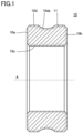
- Fig. 1 is a cross-sectional view of inner ring 10.
- inner ring 10 has a surface. More specifically, inner ring 10 has a width surface 10a, a width surface 10b, an inner circumferential surface 10c, and an outer circumferential surface 10d as the surface.
- a central axis of inner ring 10 is defined as a central axis A.
- a direction along central axis A is defined as an axial direction.
- a direction that is orthogonal to the axial direction and passes through central axis A is defined as a radial direction.
- a direction along a circumference around central axis A is defined as a circumferential direction.
- Width surface 10a and width surface 10b each form an end surface of inner ring 10 in the axial direction.
- Width surface 10b is a surface opposite to width surface 10a.
- Inner circumferential surface 10c extends along the circumferential direction.
- Inner circumferential surface 10c faces toward central axis A.
- One and the other axial ends of inner circumferential surface 10c are contiguous to width surface 10a and width surface 10b, respectively.
- Inner ring 10 is fitted to a shaft (not shown) at inner circumferential surface 10c.
- Outer circumferential surface 10d extends along the circumferential direction. Outer circumferential surface 10d faces a side opposite to central axis A. In other words, outer circumferential surface 10d is a surface opposite to inner circumferential surface 10c in the radial direction. One and the other axial ends of outer circumferential surface 10d are contiguous to width surface 10a and width surface 10b, respectively.
- Outer circumferential surface 10d has a raceway surface 10da.
- Raceway surface 10da is a portion of outer circumferential surface 10d that comes in contact with a rolling element.
- Raceway surface 10da is located in the center of outer circumferential surface 10d in the axial direction.
- Raceway surface 10da extends along the circumferential direction.
- Outer circumferential surface 10d is recessed toward inner circumferential surface 10c in raceway surface 10da.
- raceway surface 10da is, for example, in a shape of a partial arc.
- Inner ring 10 is made of steel subjected to quenching and tempering.
- steel that forms inner ring 10 contains martensite and retained austenite.
- the surface (width surface 10a, width surface 10b, inner circumferential surface 10c, and outer circumferential surface 10d) of inner ring 10 has been subjected to nitriding treatment.
- a nitrided layer 11 is formed at the surface of inner ring 10. Nitrogen is in a state of solid solution in steel in nitrided layer 11, and does not form a nitride in nitrided layer 11.
- Steel that forms inner ring 10 contains at least 0.95 mass % and at most 1.10 mass % of carbon, less than 0.30 mass % of silicon, less than 0.50 mass % of manganese, less than 0.0080 mass % of sulfur, and at least 1.3 mass % and at most 1.6 mass % of chromium.
- a remainder of steel that forms inner ring 10 is composed of iron and an inevitable impurity.
- Steel that forms inner ring 10 does not have to contain silicon, manganese, and sulfur.
- steel that forms inner ring 10 include bearing steel.
- bearing steel include SUJ2 defined under JIS standards, 52100 defined under ASTM standards, 100Cr6 defined under ISO standards, and GCr15 defined under GB standards.
- An average nitrogen concentration at the surface of inner ring 10 is equal to or more than 0.10 mass %.
- the average nitrogen concentration at the surface of inner ring 10 is measured by line analysis with the use of an electron probe micro analyzer (EPMA). At this time, a calibration curve is drawn by using a standard sample, a concentration of nitrogen in which is clearly known.
- An amount of retained austenite at the surface of inner ring 10 is equal to or less than 20 volume %.
- the amount of retained austenite at the surface of inner ring 10 is measured by an X-ray diffraction method. This measurement is conducted by using an X-ray diffraction apparatus of a Cr tube type. In the X-ray diffraction apparatus of the Cr tube type, a wavelength of Cr-K ⁇ rays is set to 2.29093 ⁇ 10 -10 m, a tube voltage is set to 30 kV, a tube current is set to 10 mA, and a collimator size is set to 2 mm ⁇ 2 mm.
- a hardness at the surface of inner ring 10 is equal to or more than 850 Hv.
- the hardness at the surface of inner ring 10 is measured in accordance with a Vickers hardness test method defined under the JIS standards.
- a load in measurement of the hardness at the surface of inner ring 10 is set to 300 g.
- the hardness at the surface of inner ring 10 is measured at at least three different points and an average value of measurement values is adopted.
- a half value width in an X-ray profile of martensite obtained by X-ray diffraction onto the surface of inner ring 10 is preferably not smaller than 7.2° and not larger than 8.0°.
- a position (2 ⁇ ) of a peak indicating a ⁇ 220 ⁇ plane in an X-ray profile of austenite obtained by X-ray diffraction onto the surface of inner ring 10 is preferably equal to or larger than 128°.
- a lattice plane spacing of austenite at the surface of inner ring 10 is preferably equal to or less than 1.275 ⁇ 10 -10 m.
- the X-ray profile of martensite and the X-ray profile of austenite obtained by X-ray diffraction onto the surface of inner ring 10 are obtained with the use of the X-ray diffraction apparatus of the Cr tube type.
- a wavelength of Cr-K ⁇ rays is set to 2.29093 ⁇ 10 -10 m
- a tube voltage is set to 30 kV
- a tube current is set to 10 mA
- a collimator size is set to 2 mm ⁇ 2 mm.
- the X-ray profile of martensite obtained by X-ray diffraction onto the surface of inner ring 10 is measured within a range where 20 is not smaller than 142.75° and not larger than 170.8°, and the X-ray profile of austenite obtained by X-ray diffraction onto the surface of inner ring 10 is measured within a range where 20 is not smaller than 114.75° and not larger than 142.8°.
- the X-ray profile of martensite and the X-ray profile of austenite obtained by X-ray diffraction onto the surface of inner ring 10 are subjected to background processing.
- the position of the peak indicating the ⁇ 220 ⁇ plane in the X-ray profile of austenite obtained by X-ray diffraction onto the surface of inner ring 10 is obtained from a central position of the half value width.
- the lattice plane spacing of austenite at the surface of inner ring 10 is calculated by applying the Bragg's equation below to the X-ray profile of austenite obtained by X-ray diffraction onto the surface of inner ring 10.
- d represents the lattice plane spacing (unit: m) of austenite at the surface of inner ring 10
- ⁇ represents the wavelength (unit: m) of Cr-K ⁇ rays used in the X-ray diffraction apparatus of the Cr tube type
- ⁇ represents a diffraction angle (unit: °) in the X-ray profile of austenite obtained by X-ray diffraction onto the surface of inner ring 10.
- d ⁇ 2 sin ⁇
- a dislocation density of martensite at the surface of inner ring 10 is preferably equal to or more than 1.1 ⁇ 10 15 m -2 .
- a dislocation density of austenite at the surface of inner ring 10 is preferably equal to or more than 2.5 ⁇ 10 14 m -2 .
- the dislocation density of martensite and the dislocation density of austenite at the surface of inner ring 10 are measured with the use of an X-ray diffraction apparatus of a Co tube type. More specifically, firstly, the X-ray profiles of martensite and austenite at the surface of inner ring 10 are obtained with the use of the X-ray diffraction apparatus of the Co tube type.
- a wavelength of Co-K ⁇ rays is set to 1.7889 ⁇ 10 -10 m
- a tube voltage is set to 40 kV
- a tube current is set to 50 mA
- a collimator size is set to a diameter of 1 mm.
- the X-ray profiles of martensite and austenite obtained by X-ray diffraction onto the surface of inner ring 10 are measured within a range where 20 is not smaller than 30° and not larger than 135°.
- Rietveld analysis is conducted, and then a half value width of a peak in each of the X-ray profiles of martensite and austenite obtained by X-ray diffraction onto the surface of inner ring 10 is separated into a crystallite size and strain.
- peaks indicating a ⁇ 110 ⁇ plane, a ⁇ 200 ⁇ plane, a ⁇ 211 ⁇ plane, and a ⁇ 220 ⁇ plane are to be measured.
- peaks indicating a ⁇ 111 ⁇ plane, a ⁇ 200 ⁇ plane, a ⁇ 220 ⁇ plane, a ⁇ 311 ⁇ plane, and a ⁇ 222 ⁇ plane are to be measured.
- Rietveld analysis is conducted in order to lessen influence by the ⁇ 200 ⁇ plane of martensite and the ⁇ 200 ⁇ plane of austenite different in modulus of elasticity.
- a depth of an indentation formed at the time of application of a maximum contact pressure of 4.5 GPa to the surface (raceway surface 10da) of inner ring 10 is preferably equal to or less than 0.2 ⁇ m.
- This depth of the indentation is measured with the use of a white light interferometric function of a laser microscope at the surface of inner ring 10 after a ceramic ball is brought in contact with the surface of inner ring 10 with the use of an autograph such that the maximum contact pressure attains to 4.5 GPa.
- a loading speed at this time is set to 3 N/second and a load is held for 120 seconds after a target load is reached.
- a static load capacity at the surface of inner ring 10 is preferably equal to or more than 6.0 GPa.
- an indentation is formed in the surface of inner ring 10 with the maximum contact pressure being varied as above with the autograph.
- a value is calculated by dividing the depth of the indentation by a diameter of the ceramic ball.
- the maximum contact pressure at the time when the value calculated by dividing the depth of the indentation by the diameter of the ceramic ball is 1/10000 is defined as the static load capacity at the surface of inner ring 10.
- the amount of retained austenite at the surface of inner ring 10, the average nitrogen concentration at the surface of inner ring 10, and the dislocation density of austenite at the surface of inner ring 10 are denoted as A (unit: volume %), B (unit: mass %), and C (unit: m -2 ). Relation of 4.332+0.005 ⁇ A-0.580 ⁇ B-0.295 ⁇ LogC ⁇ 0 is preferably satisfied in inner ring 10.
- the dislocation density of martensite at the surface of inner ring 10 is denoted as D (unit: m -2 ). Relation of -47.73-0.025 ⁇ A-2.141 ⁇ B+3.155 ⁇ LogD ⁇ 0 is satisfied at the surface of inner ring 10.
- Fig. 2 is a process diagram showing a method of manufacturing inner ring 10.
- the method of manufacturing inner ring 10 includes a preparation step S1, a nitriding treatment step S2, a quenching step S3, a sub zero treatment step S4, a tempering step S5, and a post-treatment step S6.
- a member to be worked is prepared.
- Nitriding treatment step S2 is performed after preparation step S1.
- the member to be worked is held at a temperature equal to or more than an A 1 transformation point in atmospheric gas containing a nitrogen source.
- Nitriding treatment step S2 is performed such that nitrogen is introduced and diffused to a position to be the surface of inner ring 10 after post-treatment step S6.
- Quenching step S3 is performed after nitriding treatment step S2.
- the member to be worked is held at the temperature equal to or more than the A 1 transformation point and thereafter cooled to a temperature equal to or less than an Ms transformation point.
- Sub zero treatment step S4 is performed after quenching step S3.
- the member to be worked is cooled to a temperature exceeding -100°C and not higher than a room temperature. Some of retained austenite formed in steel that forms the member to be worked in quenching step S3 thus transforms to martensite.
- Cryogenic treatment step S7 may be performed instead of sub zero treatment step S4. In cryogenic treatment step S7, the member to be worked is cooled to a temperature equal to or lower than -100°C. Some of retained austenite formed in steel that forms the member to be worked in quenching step S3 thus transforms to martensite.
- sub zero treatment step S4 and cryogenic treatment step S7 are employed as refrigerant in sub zero treatment step S4 and cryogenic treatment step S7.
- sub zero treatment step S4 and cryogenic treatment step S7 are performed within two hours after end of quenching step S3.
- Tempering step S5 is performed after sub zero treatment step S4 (cryogenic treatment step S7).
- tempering step S5 the member to be worked is held at a temperature lower than the A 1 transformation point. Some of martensite in steel that forms the member to be worked is thus decomposed.
- a holding temperature in tempering step S5 is, for example, not lower than 180°C and not higher than 220°C.
- a holding time period in tempering step S5 is set, for example, to two hours.
- Post-treatment step S6 is performed after tempering step S5.
- the surface of the member to be worked is machined (for example, ground and polished).
- Inner ring 10 in a structure shown in Fig. 1 is manufactured as set forth above.
- tempering at a high temperature for example, equal to or higher than 230°C
- martensite formed by quenching is excessively decomposed by tempering, which may result in a lower hardness at the surface of the raceway surface and an insufficient static load capacity at the surface of the raceway surface.
- inner ring 10 nitrogen is dissolved in nitrided layer 11 as a solid solution, and the surface of inner ring 10 is reinforced by the solid solution. Furthermore, in inner ring 10, as a result of sub zero treatment step S4 (cryogenic treatment step S7), the amount of retained austenite at the surface has decreased (martensite has increased) and the dislocation densities in retained austenite and martensite at the surface have increased. Consequently, inner ring 10 has the hardness at the surface equal to or more than 850 Hv. Therefore, according to inner ring 10, the static load capacity at the surface is improved as compared with the case of tempering at the high temperature.
- the depth of the indentation at the time of application of the maximum contact pressure of 4.5 GPa to the surface of inner ring 10 is equal to or less than 0.2 ⁇ m and the static load capacity at the surface of inner ring 10 is equal to or more than 6.0 GPa.
- Nitrogen is an element that stabilizes austenite and nitriding treatment is performed to enrich retained austenite at the surface of the raceway surface. Therefore, when nitriding treatment is performed, normally, sub zero treatment (or cryogenic treatment) to decrease the amount of retained austenite at the surface is not performed.
- a sample 1 to a sample 6 were prepared.
- the sample 1 to the sample 6 were each in a form of a flat plate having a diameter of 85 mm ⁇ a thickness of 5 mm.
- the sample 1 to the sample 6 were formed of SUJ2 defined under the JIS standards. Table 1 shows details of heat treatment onto the sample 1 to the sample 6.
- nitriding treatment step S2, quenching step S3, cryogenic treatment step S7, and tempering step S5 were performed as heat treatment.
- nitriding treatment step S2, quenching step S3, sub zero treatment step S4, and tempering step S5 were performed as heat treatment.
- the sample 1 to the sample 3 were samples that simulated the mechanical component according to the embodiment.
- tempering step S5 for the sample 1 to the sample 3 the holding temperature was set to 180°C.
- nitriding treatment step S2, quenching step S3, and tempering step S5 were performed as heat treatment, and sub zero treatment step S4 (or cryogenic treatment step S7) was not performed.
- tempering step S5 for the sample 4 tempering at the high temperature (specifically, at 230°C) was performed.
- nitriding treatment step S2, quenching step S3, and tempering step S5 were performed as heat treatment, and sub zero treatment step S4 (or cryogenic treatment step S7) was not performed.
- the holding temperature was set to 180°C.
- quenching step S3 and tempering step S5 were performed as heat treatment, and nitriding treatment step S2 and sub zero treatment step S4 (or cryogenic treatment step S7) were not performed.
- tempering step S5 for the sample 5 the holding temperature was set to 180°C.
- the average nitrogen concentration at the surface, the hardness at the surface, the amount of retained austenite at the surface, the depth of the indentation at the time of application of the maximum contact pressure of 4.5 GPa to the surface, and the static load capacity at the surface of the sample 1 to the sample 6 were measured.
- Table 2 shows results of measurement of the average nitrogen concentration at the surface, the hardness at the surface, the amount of retained austenite at the surface, the depth of the indentation at the time of application of the maximum contact pressure of 4.5 GPa to the surface, and the static load capacity at the surface.
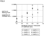
- Fig. 3 shows a graph of relation between the maximum contact pressure at the surface of each of the sample 1 to the sample 6 and a value calculated by dividing the depth of the indentation by the diameter of the ceramic ball. The diameter of the ceramic ball was set to 3/8 inch (9.525 mm).
- the average nitrogen concentration at the surface being equal to or more than 0.10 mass %, the hardness at the surface being equal to or more than 850 Hv, and the amount of retained austenite at the surface being equal to or less than 20 volume % are defined as a condition 1, a condition 2, and a condition 3, respectively.
- the sample 1 to the sample 3 satisfied all of the condition 1, the condition 2, and the condition 3.
- the sample 4 to the sample 6 did not satisfy at least one of the condition 1, the condition 2, and the condition 3.
- the depth of the indentation at the time of application of the maximum contact pressure of 4.5 GPa to the surface was equal to or less than 0.2 ⁇ m and the static load capacity at the surface was equal to or more than 6.0 GPa.
- the depth of the indentation at the time of application of the maximum contact pressure of 4.5 GPa to the surface was more than 0.2 ⁇ m and the static load capacity at the surface was lower than 6.0 GPa. It was clarified also experimentally based on this comparison that the static load capacity at the surface was improved by satisfaction of the condition 1, the condition 2, and the condition 3.
- a sample 1-1 to a sample 1-3, a sample 2-1 to a sample 2-3, and a sample 3-1 to a sample 3-3 were samples subjected to heat treatment similarly to the sample 1, the sample 2, and the sample 3, respectively.
- a sample 4-1 to a sample 4-4 are samples subjected to heat treatment similarly to the sample 4.
- a steel type and a shape of these samples were SUJ2 and a flat plate having a diameter of 85 mm ⁇ a thickness of 5 mm, respectively.
- the sample 4-1 to the sample 4-4 did not satisfy at least one of the condition 1, the condition 2, and the condition 3.
- the half value width in the X-ray profile of martensite obtained by X-ray diffraction onto the surface was not smaller than 7.2° and not larger than 8.0° and the peak position indicating the ⁇ 220 ⁇ plane in the X-ray profile of austenite obtained by X-ray diffraction onto the surface was equal to or larger than 128°.
- the half value width in the X-ray profile of martensite obtained by X-ray diffraction onto the surface was smaller than 7.2° and the peak position indicating the ⁇ 220 ⁇ plane in the X-ray profile of austenite obtained by X-ray diffraction onto the surface was smaller than 128°.
- the half value width in the X-ray profile of martensite obtained by X-ray diffraction onto the surface was not smaller than 7.2° and not larger than 8.0° and the peak position indicating the ⁇ 220 ⁇ plane in the X-ray profile of austenite obtained by X-ray diffraction onto the surface was equal to or larger than 128°.
- the dislocation density of martensite and the dislocation density of austenite at the surface were equal to or more than 1.1 ⁇ 10 15 m -2 and equal to or more than 2.5 ⁇ 10 14 m -2 , respectively.
- the half value width in the X-ray profile of martensite obtained by X-ray diffraction onto the surface was smaller than 7.2° and the peak position indicating the ⁇ 220 ⁇ plane in the X-ray profile of austenite obtained by X-ray diffraction onto the surface was smaller than 128°.
- the dislocation density of martensite and the dislocation density of austenite at the surface were less than 1.1 ⁇ 10 15 m -2 and less than 2.5 ⁇ 10 14 m -2 , respectively.
- a coefficient of determination (R 2 ) for this expression is 0.94. Therefore, when relation of 4.332+0.005 ⁇ A-0.580 ⁇ B-0.295 ⁇ LogC ⁇ 0 is satisfied, the depth of the indentation at the time of application of the maximum contact pressure of 4.5 GPa to the surface can be equal to or less than 0.2 ⁇ m.
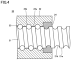
- Fig. 4 is a cross-sectional view of a ball screw 20.
- ball screw 20 includes a screw shaft 21, a ball nut 22, a plurality of balls 23, and a sealing member 24.
- a system of circulation of balls 23 in ball screw 20 is not particularly limited.
- the system of circulation of balls 23 in ball screw 20 is, for example, a tube system, a return tube (pipe) system, a deflector system, an end deflector system, an end cap system, an internal defector system, and the like.
- Screw shaft 21 has an outer circumferential surface 21a.
- a thread 21b is provided in outer circumferential surface 21a.
- Ball nut 22 is provided with a hole that extends along a direction of a central axis of screw shaft 21. An inner wall surface of this hole is an inner circumferential surface 22a of ball nut 22.
- Inner circumferential surface 22a is provided with a thread 22b.
- Screw shaft 21 is inserted in ball nut 22 such that outer circumferential surface 21a is opposed to inner circumferential surface 22a.
- Ball 23 is arranged between thread 21b and thread 22b. The hole in ball nut 22 through which screw shaft 21 passes is closed by sealing member 24. Screw shaft 21 passes also through a hole provided in sealing member 24.
- Screw shaft 21, ball nut 22, and ball 23 are formed of steel subjected to quenching and tempering.
- This steel contains at least 0.95 mass % and at most 1.10 mass % of carbon, less than 0.30 mass % of silicon, less than 0.50 mass % of manganese, less than 0.0080 mass % of sulfur, and at least 1.3 mass % and at most 1.6 mass % of chromium. A remainder of this steel is composed of iron and an inevitable impurity.
- This steel is, for example, bearing steel (SUJ2 defined under the JIS standards, 52100 defined under the ASTM standards, 100Cr6 defined under the ISO standards, GCr15 defined under the GB standards, and the like).
- Screw shaft 21, ball nut 22, and ball 23 are each provided with nitrided layer 11 (not shown in Fig. 4 ) at a surface, and an average nitrogen concentration at the surface is equal to or more than 0.10 mass %.
- a hardness at the surface of each of screw shaft 21, ball nut 22, and ball 23 is equal to or more than 850 Hv.
- An amount of retained austenite at the surface of each of screw shaft 21, ball nut 22, and ball 23 is equal to or less than 20 volume %.
- screw shaft 21, ball nut 22, and ball 23 are mechanical components according to the embodiment.
- ball screw 20 Since ball screw 20 has an improved static load capacity at the surfaces of screw shaft 21, ball nut 22, and ball 23, it can also achieve a higher load capacity and reduction in size and weight. With reduction in size of ball screw 20, reduction in size also of a peripheral component or a structural member can also be achieved.
- At least one of screw shaft 21, ball nut 22, and ball 23 should satisfy the composition of steel, the hardness at the surface, the concentration of nitrogen at the surface, and the amount of retained austenite at the surface described above. From another point of view, at least one of screw shaft 21, ball nut 22, and ball 23 of ball screw 20 should be the mechanical component according to the embodiment.
- ball screw 20 is an apparatus that converts rotational motion of a motor or the like to linear motion.
- Ball screw 20 is used, for example, in an electric actuator, a positioning apparatus, an electric jack, a servo cylinder, an electric servo pressing machine, a mechanical pressing machine, an electric brake apparatus, a transmission, an electric power steering apparatus, an electric injection molding machine, and the like.
- Fig. 5 is a cross-sectional view of a rolling bearing 100.
- rolling bearing 100 includes inner ring 10, an outer ring 30, a plurality of rolling elements 40, and a retainer 50.
- Outer ring 30 has a width surface 30a, a width surface 30b, an inner circumferential surface 30c, and an outer circumferential surface 30d.
- Width surface 30a and width surface 30b each form an end surface of outer ring 30 in the axial direction.
- Width surface 30b is a surface opposite to width surface 30a.
- Inner circumferential surface 30c and outer circumferential surface 30d extend along the circumferential direction.
- Inner circumferential surface 30c and outer circumferential surface 30d face toward central axis A and a side opposite to central axis A, respectively.
- Outer ring 30 is fitted to a housing (not shown) at outer circumferential surface 30d.
- Outer ring 30 is arranged on a radially outer side of inner ring 10 such that inner circumferential surface 30c is opposed to outer circumferential surface 10d.
- Inner circumferential surface 30c has a raceway surface 30ca.
- Raceway surface 30ca is a portion of inner circumferential surface 30c that comes in contact with rolling element 40.
- Raceway surface 30ca is located in the center of inner circumferential surface 30c in the axial direction.
- Raceway surface 30ca extends along the circumferential direction.
- Inner circumferential surface 30c is recessed toward outer circumferential surface 30d in raceway surface 30ca.
- raceway surface 30ca is, for example, in a form of a partial arc.
- Raceway surface 30ca is opposed to raceway surface 10da.
- Rolling element 40 is, for example, spherical. Rolling element 40 is arranged between raceway surface 10da and raceway surface 30ca. The plurality of rolling elements 40 are aligned at intervals in the circumferential direction. Retainer 50 holds the plurality of rolling elements 40 such that an interval between two adjacent rolling elements 40 is within a certain range. Retainer 50 is arranged between outer circumferential surface 10d and inner circumferential surface 30c.
- Outer ring 30 and rolling element 40 are, for example, mechanical components according to the embodiment.
- outer ring 30 and rolling element 40 are formed of steel subjected to quenching and tempering, and steel contains at least 0.95 mass % and at most 1.10 mass % of carbon, less than 0.30 mass % of silicon, less than 0.50 mass % of manganese, less than 0.0080 mass % of sulfur, at least 1.3 mass % and at most 1.6 mass % of chromium, and a remainder composed of iron and an inevitable impurity.
- Outer ring 30 and rolling element 40 each have the average nitrogen concentration at the surface not lower than 0.10 mass %, the hardness at the surface not lower than 850 Hv, and the amount of retained austenite at the surface not higher than 20 volume %. Outer ring 30 and rolling element 40 do not have to be the mechanical components according to the embodiment.
Landscapes
- Engineering & Computer Science (AREA)
- Chemical & Material Sciences (AREA)
- Mechanical Engineering (AREA)
- General Engineering & Computer Science (AREA)
- Materials Engineering (AREA)
- Metallurgy (AREA)
- Organic Chemistry (AREA)
- Crystallography & Structural Chemistry (AREA)
- Physics & Mathematics (AREA)
- Thermal Sciences (AREA)
- Chemical Kinetics & Catalysis (AREA)
- Manufacturing & Machinery (AREA)
- Heat Treatment Of Articles (AREA)
- Rolling Contact Bearings (AREA)
- Solid-Phase Diffusion Into Metallic Material Surfaces (AREA)
- Transmission Devices (AREA)
Abstract
Description
- The present invention relates to a mechanical component.
- For example,
Japanese Patent Laying-Open No. 2013-119930 PTL 1 comes in contact with another component at its surface. The bearing component described inPTL 1 is made of steel subjected to quenching and tempering. Steel contains at least 0.90 mass % and at most 1.05 mass % of carbon, at least 0.15 mass % and at most 0.35 mass % of silicon, at least 0.01 mass % and at most 0.50 mass % of manganese, at least 1.30 mass % and at most 1.65 mass % of chromium, and a remainder composed of iron and an inevitable impurity. - In the bearing component described in
PTL 1, the surface is nitrided, and a concentration of nitrogen at the surface is equal to or more than 0.25 mass %. In the bearing component described inPTL 1, an amount of retained austenite at the surface is at least 6 volume % and at most 12 volume %. The bearing component described inPTL 1 has an improved static load capacity at the surface owing to tempering at a high temperature. - PTL 1:
Japanese Patent Laying-Open No. 2013-119930 - A bearing is used in a motor, a gear box, a differential gear, and the like mounted on a battery electric vehicle. In addition, a bearing is used also in electric variable timing control (VTC), an electric compressor, a transmission, an axle, and the like mounted on a plug-in hybrid vehicle (PHV), a hybrid vehicle (HV), or an engine vehicle. Improvement in static load capacity of the bearing in such applications enables reduction in size of the bearing and reduction in size of a peripheral mechanical component.
- A bearing mounted on a hydrogen-utilizing device used in a hydrogen environment such as a fuel cell vehicle or a hydrogen station can also be reduced in size as a result of improvement in static load capacity, and efficiency of the hydrogen-utilizing device may improve. There is a room, however, for improvement in static load capacity at the surface in the bearing component described in
PTL 1. - The present invention was made in view of the problem of the conventional art as above. More specifically, the present invention provides a mechanical component improved in static load capacity at a surface.
- A mechanical component in the present invention has a surface and is made of steel subjected to quenching and tempering. The mechanical component is provided with a nitrided layer formed at the surface. Steel contains at least 0.95 mass % and at most 1.10 mass % of carbon, less than 0.30 mass % of silicon, less than 0.50 mass % of manganese, less than 0.0080 mass % of sulfur, at least 1.3 mass % and at most 1.6 mass % of chromium, and a remainder composed of iron and an inevitable impurity. An average nitrogen concentration at the surface is equal to or more than 0.10 mass %. A hardness at the surface is equal to or more than 850 Hv. An amount of retained austenite at the surface is equal to or less than 20 volume %.
- In the mechanical component above, a half value width in an X-ray profile of martensite obtained by X-ray diffraction onto the surface may be not smaller than 7.2° and not larger than 8.0°. A peak position indicating a {220} plane in an X-ray profile of austenite obtained by X-ray diffraction onto the surface may be equal to or larger than 128°.
- In the mechanical component above, a dislocation density of martensite at the surface may be equal to or more than 1.1 × 10¹⁵ m-2. A dislocation density of austenite at the surface may be equal to or more than 2.5 × 10¹⁴ m-2.
- In the mechanical component above, relation of 4.332+0.005×A-0.580×B-0.295×LogC ≤ 0 may be satisfied, where A (unit: volume %) represents the amount of retained austenite at the surface, B (unit: mass %) represents the average nitrogen concentration at the surface, and C (unit: m-2) represents a dislocation density of austenite at the surface.
- In the mechanical component above, relation of -47.73-0.025×A-2.141×B+3.155×LogD ≥ 0 may be satisfied, where A (unit: volume %) represents the amount of retained austenite at the surface, B (unit: mass %) represents the average nitrogen concentration at the surface, and D (unit: m-2) represents a dislocation density of martensite at the surface.
- In the mechanical component above, a depth of an indentation formed in the surface when a maximum contact pressure of 4.5 GPa is applied to the surface may be equal to or less than 0.2 µm. In the mechanical component above, a static load capacity at the surface may be equal to or more than 6.0 GPa.
- According to the mechanical component in the present invention, the static load capacity at the surface can be improved.
-
-
Fig. 1 is a cross-sectional view of aninner ring 10. -
Fig. 2 is a process diagram showing a method of manufacturinginner ring 10. -
Fig. 3 shows a graph of relation between a maximum contact pressure at surfaces of asample 1 to asample 6 and a value calculated by dividing a depth of an indentation by a diameter of a ceramic ball. -
Fig. 4 is a cross-sectional view of aball screw 20. -
Fig. 5 is a cross-sectional view of a rolling bearing 100. - Details of an embodiment of the present invention will be described with reference to the drawings. The same or corresponding elements in the drawings below have the same reference characters allotted and redundant description will not be repeated.
- A mechanical component according to the embodiment is, for example, a raceway surface of a rolling bearing. The mechanical component according to the embodiment may be a sliding member such as a rolling element, a shaft, or a ball screw of the rolling bearing. Though the mechanical component according to the embodiment is not limited as such, an
inner ring 10 of a deep groove ball bearing will be described below by way of example of the mechanical component according to the embodiment. - A construction of
inner ring 10 will be described below. -
Fig. 1 is a cross-sectional view ofinner ring 10. As shown inFig. 1 ,inner ring 10 has a surface. More specifically,inner ring 10 has awidth surface 10a, awidth surface 10b, an innercircumferential surface 10c, and an outercircumferential surface 10d as the surface. A central axis ofinner ring 10 is defined as a central axis A. A direction along central axis A is defined as an axial direction. A direction that is orthogonal to the axial direction and passes through central axis A is defined as a radial direction. A direction along a circumference around central axis A is defined as a circumferential direction. -
Width surface 10a andwidth surface 10b each form an end surface ofinner ring 10 in the axial direction.Width surface 10b is a surface opposite towidth surface 10a. Innercircumferential surface 10c extends along the circumferential direction. Innercircumferential surface 10c faces toward central axis A. One and the other axial ends of innercircumferential surface 10c are contiguous towidth surface 10a andwidth surface 10b, respectively.Inner ring 10 is fitted to a shaft (not shown) at innercircumferential surface 10c. - Outer
circumferential surface 10d extends along the circumferential direction. Outercircumferential surface 10d faces a side opposite to central axis A. In other words, outercircumferential surface 10d is a surface opposite to innercircumferential surface 10c in the radial direction. One and the other axial ends of outercircumferential surface 10d are contiguous towidth surface 10a andwidth surface 10b, respectively. - Outer
circumferential surface 10d has a raceway surface 10da. Raceway surface 10da is a portion of outercircumferential surface 10d that comes in contact with a rolling element. Raceway surface 10da is located in the center of outercircumferential surface 10d in the axial direction. Raceway surface 10da extends along the circumferential direction. Outercircumferential surface 10d is recessed toward innercircumferential surface 10c in raceway surface 10da. In a cross-sectional view orthogonal to the circumferential direction, raceway surface 10da is, for example, in a shape of a partial arc. -
Inner ring 10 is made of steel subjected to quenching and tempering. In other words, steel that formsinner ring 10 contains martensite and retained austenite. The surface (width surface 10a,width surface 10b, innercircumferential surface 10c, and outercircumferential surface 10d) ofinner ring 10 has been subjected to nitriding treatment. In other words, anitrided layer 11 is formed at the surface ofinner ring 10. Nitrogen is in a state of solid solution in steel innitrided layer 11, and does not form a nitride innitrided layer 11. - Steel that forms
inner ring 10 contains at least 0.95 mass % and at most 1.10 mass % of carbon, less than 0.30 mass % of silicon, less than 0.50 mass % of manganese, less than 0.0080 mass % of sulfur, and at least 1.3 mass % and at most 1.6 mass % of chromium. A remainder of steel that formsinner ring 10 is composed of iron and an inevitable impurity. Steel that formsinner ring 10 does not have to contain silicon, manganese, and sulfur. - Specific examples of steel that forms
inner ring 10 include bearing steel. Specific examples of bearing steel include SUJ2 defined under JIS standards, 52100 defined under ASTM standards, 100Cr6 defined under ISO standards, and GCr15 defined under GB standards. - An average nitrogen concentration at the surface of
inner ring 10 is equal to or more than 0.10 mass %. The average nitrogen concentration at the surface ofinner ring 10 is measured by line analysis with the use of an electron probe micro analyzer (EPMA). At this time, a calibration curve is drawn by using a standard sample, a concentration of nitrogen in which is clearly known. - An amount of retained austenite at the surface of
inner ring 10 is equal to or less than 20 volume %. The amount of retained austenite at the surface ofinner ring 10 is measured by an X-ray diffraction method. This measurement is conducted by using an X-ray diffraction apparatus of a Cr tube type. In the X-ray diffraction apparatus of the Cr tube type, a wavelength of Cr-Kα rays is set to 2.29093×10⁻¹⁰ m, a tube voltage is set to 30 kV, a tube current is set to 10 mA, and a collimator size is set to 2 mm × 2 mm. - A hardness at the surface of
inner ring 10 is equal to or more than 850 Hv. The hardness at the surface ofinner ring 10 is measured in accordance with a Vickers hardness test method defined under the JIS standards. A load in measurement of the hardness at the surface ofinner ring 10 is set to 300 g. The hardness at the surface ofinner ring 10 is measured at at least three different points and an average value of measurement values is adopted. - A half value width in an X-ray profile of martensite obtained by X-ray diffraction onto the surface of
inner ring 10 is preferably not smaller than 7.2° and not larger than 8.0°. A position (2θ) of a peak indicating a {220} plane in an X-ray profile of austenite obtained by X-ray diffraction onto the surface ofinner ring 10 is preferably equal to or larger than 128°. A lattice plane spacing of austenite at the surface ofinner ring 10 is preferably equal to or less than 1.275×10⁻¹⁰ m. - The X-ray profile of martensite and the X-ray profile of austenite obtained by X-ray diffraction onto the surface of
inner ring 10 are obtained with the use of the X-ray diffraction apparatus of the Cr tube type. In the X-ray diffraction apparatus of the Cr tube type, a wavelength of Cr-Kα rays is set to 2.29093×10⁻¹⁰ m, a tube voltage is set to 30 kV, a tube current is set to 10 mA, and a collimator size is set to 2 mm × 2 mm. The X-ray profile of martensite obtained by X-ray diffraction onto the surface ofinner ring 10 is measured within a range where 20 is not smaller than 142.75° and not larger than 170.8°, and the X-ray profile of austenite obtained by X-ray diffraction onto the surface ofinner ring 10 is measured within a range where 20 is not smaller than 114.75° and not larger than 142.8°. - The X-ray profile of martensite and the X-ray profile of austenite obtained by X-ray diffraction onto the surface of
inner ring 10 are subjected to background processing. The position of the peak indicating the {220} plane in the X-ray profile of austenite obtained by X-ray diffraction onto the surface ofinner ring 10 is obtained from a central position of the half value width. - The lattice plane spacing of austenite at the surface of
inner ring 10 is calculated by applying the Bragg's equation below to the X-ray profile of austenite obtained by X-ray diffraction onto the surface ofinner ring 10. In this equation, d represents the lattice plane spacing (unit: m) of austenite at the surface ofinner ring 10, λ represents the wavelength (unit: m) of Cr-Kα rays used in the X-ray diffraction apparatus of the Cr tube type, and θ represents a diffraction angle (unit: °) in the X-ray profile of austenite obtained by X-ray diffraction onto the surface ofinner ring 10.
- A dislocation density of martensite at the surface of
inner ring 10 is preferably equal to or more than 1.1×10¹⁵ m-2. A dislocation density of austenite at the surface ofinner ring 10 is preferably equal to or more than 2.5×10¹⁴ m-2. - The dislocation density of martensite and the dislocation density of austenite at the surface of
inner ring 10 are measured with the use of an X-ray diffraction apparatus of a Co tube type. More specifically, firstly, the X-ray profiles of martensite and austenite at the surface ofinner ring 10 are obtained with the use of the X-ray diffraction apparatus of the Co tube type. In the X-ray diffraction apparatus of a Co tube type, a wavelength of Co-Kα rays is set to 1.7889×10⁻¹⁰ m, a tube voltage is set to 40 kV, a tube current is set to 50 mA, and a collimator size is set to a diameter of 1 mm. The X-ray profiles of martensite and austenite obtained by X-ray diffraction onto the surface ofinner ring 10 are measured within a range where 20 is not smaller than 30° and not larger than 135°. - Secondly, Rietveld analysis is conducted, and then a half value width of a peak in each of the X-ray profiles of martensite and austenite obtained by X-ray diffraction onto the surface of
inner ring 10 is separated into a crystallite size and strain. Thirdly, the dislocation density of martensite and the dislocation density of austenite at the surface ofinner ring 10 are obtained by applying the crystallite size and the strain to a Williamson-Hall equation below, where ρ represents the dislocation density (unit: m-2), ε represents the strain, and b represents a length of a Burgers vector (b = 0.25×10⁻⁹ m).
- In the X-ray profile of martensite obtained by X-ray diffraction onto the surface of
inner ring 10, peaks indicating a {110} plane, a {200} plane, a {211} plane, and a {220} plane are to be measured. In the X-ray profile of austenite obtained by X-ray diffraction onto the surface ofinner ring 10, peaks indicating a {111} plane, a {200} plane, a {220} plane, a {311} plane, and a {222} plane are to be measured. Rietveld analysis is conducted in order to lessen influence by the {200} plane of martensite and the {200} plane of austenite different in modulus of elasticity. - A depth of an indentation formed at the time of application of a maximum contact pressure of 4.5 GPa to the surface (raceway surface 10da) of
inner ring 10 is preferably equal to or less than 0.2 µm. This depth of the indentation is measured with the use of a white light interferometric function of a laser microscope at the surface ofinner ring 10 after a ceramic ball is brought in contact with the surface ofinner ring 10 with the use of an autograph such that the maximum contact pressure attains to 4.5 GPa. A loading speed at this time is set to 3 N/second and a load is held for 120 seconds after a target load is reached. - A static load capacity at the surface of
inner ring 10 is preferably equal to or more than 6.0 GPa. In measurement of the static load capacity at the surface ofinner ring 10, firstly, similarly to the above, an indentation is formed in the surface ofinner ring 10 with the maximum contact pressure being varied as above with the autograph. Secondly, for each varied maximum contact pressure, a value is calculated by dividing the depth of the indentation by a diameter of the ceramic ball. The maximum contact pressure at the time when the value calculated by dividing the depth of the indentation by the diameter of the ceramic ball is 1/10000 is defined as the static load capacity at the surface ofinner ring 10. - The amount of retained austenite at the surface of
inner ring 10, the average nitrogen concentration at the surface ofinner ring 10, and the dislocation density of austenite at the surface ofinner ring 10 are denoted as A (unit: volume %), B (unit: mass %), and C (unit: m-2). Relation of 4.332+0.005×A-0.580×B-0.295×LogC ≤ 0 is preferably satisfied ininner ring 10. - The dislocation density of martensite at the surface of
inner ring 10 is denoted as D (unit: m-2). Relation of -47.73-0.025×A-2.141×B+3.155×LogD ≥ 0 is satisfied at the surface ofinner ring 10. - A method of manufacturing
inner ring 10 will be described below. -
Fig. 2 is a process diagram showing a method of manufacturinginner ring 10. As shown inFig. 2 , the method of manufacturinginner ring 10 includes a preparation step S1, a nitriding treatment step S2, a quenching step S3, a sub zero treatment step S4, a tempering step S5, and a post-treatment step S6. - In preparation step S1, a member to be worked is prepared. Nitriding treatment step S2 is performed after preparation step S1. In nitriding treatment step S2, the member to be worked is held at a temperature equal to or more than an A1 transformation point in atmospheric gas containing a nitrogen source. Nitriding treatment step S2 is performed such that nitrogen is introduced and diffused to a position to be the surface of
inner ring 10 after post-treatment step S6. Quenching step S3 is performed after nitriding treatment step S2. In quenching step S3, the member to be worked is held at the temperature equal to or more than the A1 transformation point and thereafter cooled to a temperature equal to or less than an Ms transformation point. - Sub zero treatment step S4 is performed after quenching step S3. In sub zero treatment step S4, the member to be worked is cooled to a temperature exceeding -100°C and not higher than a room temperature. Some of retained austenite formed in steel that forms the member to be worked in quenching step S3 thus transforms to martensite. Cryogenic treatment step S7 may be performed instead of sub zero treatment step S4. In cryogenic treatment step S7, the member to be worked is cooled to a temperature equal to or lower than -100°C. Some of retained austenite formed in steel that forms the member to be worked in quenching step S3 thus transforms to martensite.
- For example, liquid nitrogen, liquid helium, or the like is employed as refrigerant in sub zero treatment step S4 and cryogenic treatment step S7. Preferably, sub zero treatment step S4 and cryogenic treatment step S7 are performed within two hours after end of quenching step S3.
- Tempering step S5 is performed after sub zero treatment step S4 (cryogenic treatment step S7). In tempering step S5, the member to be worked is held at a temperature lower than the A1 transformation point. Some of martensite in steel that forms the member to be worked is thus decomposed. A holding temperature in tempering step S5 is, for example, not lower than 180°C and not higher than 220°C. A holding time period in tempering step S5 is set, for example, to two hours.
- Post-treatment step S6 is performed after tempering step S5. In post-treatment step S6, the surface of the member to be worked is machined (for example, ground and polished).
Inner ring 10 in a structure shown inFig. 1 is manufactured as set forth above. - An effect of
inner ring 10 will be described below. - As described in
PTL 1, in order to improve the static load capacity at the surface of the raceway surface, tempering at a high temperature (for example, equal to or higher than 230°C) may be performed. In this case, however, martensite formed by quenching is excessively decomposed by tempering, which may result in a lower hardness at the surface of the raceway surface and an insufficient static load capacity at the surface of the raceway surface. - On the other hand, in
inner ring 10, nitrogen is dissolved innitrided layer 11 as a solid solution, and the surface ofinner ring 10 is reinforced by the solid solution. Furthermore, ininner ring 10, as a result of sub zero treatment step S4 (cryogenic treatment step S7), the amount of retained austenite at the surface has decreased (martensite has increased) and the dislocation densities in retained austenite and martensite at the surface have increased. Consequently,inner ring 10 has the hardness at the surface equal to or more than 850 Hv. Therefore, according toinner ring 10, the static load capacity at the surface is improved as compared with the case of tempering at the high temperature. - More specifically, with the amount of retained austenite at the surface of
inner ring 10 being equal to or less than 20 volume %, the average nitrogen concentration at the surface ofinner ring 10 being equal to or more than 0.10 mass %, and the hardness at the surface ofinner ring 10 being equal to or more than 850 Hv, the depth of the indentation at the time of application of the maximum contact pressure of 4.5 GPa to the surface ofinner ring 10 is equal to or less than 0.2 µm and the static load capacity at the surface ofinner ring 10 is equal to or more than 6.0 GPa. - Nitrogen is an element that stabilizes austenite and nitriding treatment is performed to enrich retained austenite at the surface of the raceway surface. Therefore, when nitriding treatment is performed, normally, sub zero treatment (or cryogenic treatment) to decrease the amount of retained austenite at the surface is not performed.
- In order to evaluate the static load capacity at the surface of the mechanical component according to the embodiment, a
sample 1 to asample 6 were prepared. Thesample 1 to thesample 6 were each in a form of a flat plate having a diameter of 85 mm × a thickness of 5 mm. Thesample 1 to thesample 6 were formed of SUJ2 defined under the JIS standards. Table 1 shows details of heat treatment onto thesample 1 to thesample 6. -
Table 1 Sample Steel Type Nitriding Treatment Sub Zero Treatment Cryogenic Treatment Tempering 1 SUJ2 Yes Yes (Cryogenic Treatment) 180° C 2 SUJ2 Yes Yes (Sub Zero Treatment) 180° C 3 SUJ2 Yes Yes (Sub Zero Treatment) 180° C 4 SUJ2 Yes No 230° C 5 SUJ2 Yes No 180° C 6 SUJ2 No No 180°C - For the
sample 1, nitriding treatment step S2, quenching step S3, cryogenic treatment step S7, and tempering step S5 were performed as heat treatment. For thesample 2 and thesample 3, nitriding treatment step S2, quenching step S3, sub zero treatment step S4, and tempering step S5 were performed as heat treatment. In other words, thesample 1 to thesample 3 were samples that simulated the mechanical component according to the embodiment. In tempering step S5 for thesample 1 to thesample 3, the holding temperature was set to 180°C. - For the
sample 4, nitriding treatment step S2, quenching step S3, and tempering step S5 were performed as heat treatment, and sub zero treatment step S4 (or cryogenic treatment step S7) was not performed. In tempering step S5 for thesample 4, tempering at the high temperature (specifically, at 230°C) was performed. - For the
sample 5, nitriding treatment step S2, quenching step S3, and tempering step S5 were performed as heat treatment, and sub zero treatment step S4 (or cryogenic treatment step S7) was not performed. In tempering step S5 for thesample 5, the holding temperature was set to 180°C. For thesample 6, quenching step S3 and tempering step S5 were performed as heat treatment, and nitriding treatment step S2 and sub zero treatment step S4 (or cryogenic treatment step S7) were not performed. In tempering step S5 for thesample 5, the holding temperature was set to 180°C. - The average nitrogen concentration at the surface, the hardness at the surface, the amount of retained austenite at the surface, the depth of the indentation at the time of application of the maximum contact pressure of 4.5 GPa to the surface, and the static load capacity at the surface of the
sample 1 to thesample 6 were measured. - Table 2 shows results of measurement of the average nitrogen concentration at the surface, the hardness at the surface, the amount of retained austenite at the surface, the depth of the indentation at the time of application of the maximum contact pressure of 4.5 GPa to the surface, and the static load capacity at the surface.
Fig. 3 shows a graph of relation between the maximum contact pressure at the surface of each of thesample 1 to thesample 6 and a value calculated by dividing the depth of the indentation by the diameter of the ceramic ball. The diameter of the ceramic ball was set to 3/8 inch (9.525 mm). -
Table 2 Sample Hardness at Surface (Hv) Amount of Remaining γ at Surface (Volume %) Average Nitrogen Concentration at Surface (Mass %) Depth of Indentation (µm) Static Load Capacity (GPa) 1 934 12.6 0.46 0.042 6.72 2 856 15.6 0.36 0.100 6.44 3 862 18.5 0.38 0.097 6.36 4 783 12.1 0.17 0.230 5.82 5 772 24.3 0.25 0.320 5.84 6 730 10.0 0.00 0.280 5.56 - The average nitrogen concentration at the surface being equal to or more than 0.10 mass %, the hardness at the surface being equal to or more than 850 Hv, and the amount of retained austenite at the surface being equal to or less than 20 volume % are defined as a
condition 1, acondition 2, and acondition 3, respectively. As shown in Table 2, thesample 1 to thesample 3 satisfied all of thecondition 1, thecondition 2, and thecondition 3. On the other hand, thesample 4 to thesample 6 did not satisfy at least one of thecondition 1, thecondition 2, and thecondition 3. - As shown in Table 1 and
Fig. 3 , in thesample 1 to thesample 3, the depth of the indentation at the time of application of the maximum contact pressure of 4.5 GPa to the surface was equal to or less than 0.2 µm and the static load capacity at the surface was equal to or more than 6.0 GPa. On the other hand, in thesample 4 to thesample 6, the depth of the indentation at the time of application of the maximum contact pressure of 4.5 GPa to the surface was more than 0.2 µm and the static load capacity at the surface was lower than 6.0 GPa. It was clarified also experimentally based on this comparison that the static load capacity at the surface was improved by satisfaction of thecondition 1, thecondition 2, and thecondition 3. - A sample 1-1 to a sample 1-3, a sample 2-1 to a sample 2-3, and a sample 3-1 to a sample 3-3 were samples subjected to heat treatment similarly to the
sample 1, thesample 2, and thesample 3, respectively. A sample 4-1 to a sample 4-4 are samples subjected to heat treatment similarly to thesample 4. A steel type and a shape of these samples were SUJ2 and a flat plate having a diameter of 85 mm × a thickness of 5 mm, respectively. - [Table 3]
Table 3 Sample Hardness at Surface (Hv) Amount of Remaining γ at Surface (Volume %) Average Nitrogen Concentration at Surface (Mass %) Half Value Width of Martensite at Surface (°) Peak Position in {220} Plane of Austenite at Surface (°) 1-1 934 12.6 0.45 7.31 128.5 1-2 897 10.3 0.23 7.45 128.8 1-3 876 9.4 0.14 7.47 128.9 2-1 856 15.6 0.36 7.35 128.2 2-2 847 13.8 0.20 7.42 128.3 2-3 851 12.6 0.11 7.39 128.5 3-1 862 18.5 0.38 7.44 128.1 3-2 868 17.3 0.19 7.48 128.2 3-3 858 16.1 0.12 7.53 128.4 4-1 773 14.9 0.43 6.73 126.8 4-2 783 12.1 0.17 6.80 126.9 4-3 764 10.5 0.11 6.74 126.9 4-4 764 7.2 0.07 6.72 127.2 - As shown in Table 3, the sample 1-1 to the sample 1-3, the sample 2-1 to the sample 2-3, and the sample 3-1 to the sample 3-3 satisfied all of the
condition 1, thecondition 2, and thecondition 3. On the other hand, the sample 4-1 to the sample 4-4 did not satisfy at least one of thecondition 1, thecondition 2, and thecondition 3. - In the sample 1-1 to the sample 1-3, the sample 2-1 to the sample 2-3, and the sample 3-1 to the sample 3-3, the half value width in the X-ray profile of martensite obtained by X-ray diffraction onto the surface was not smaller than 7.2° and not larger than 8.0° and the peak position indicating the {220} plane in the X-ray profile of austenite obtained by X-ray diffraction onto the surface was equal to or larger than 128°.
- On the other hand, in the sample 4-1 to the sample 4-4, the half value width in the X-ray profile of martensite obtained by X-ray diffraction onto the surface was smaller than 7.2° and the peak position indicating the {220} plane in the X-ray profile of austenite obtained by X-ray diffraction onto the surface was smaller than 128°.
- It was thus clarified based on this comparison that, when the
condition 1, thecondition 2, and thecondition 3 were satisfied, the half value width in the X-ray profile of martensite obtained by X-ray diffraction onto the surface was not smaller than 7.2° and not larger than 8.0° and the peak position indicating the {220} plane in the X-ray profile of austenite obtained by X-ray diffraction onto the surface was equal to or larger than 128°. - From another point of view, it was clarified that, by performing sub zero treatment step S4 or cryogenic treatment step S7 without performing tempering step S5 at the high temperature, the dislocation density of martensite at the surface became higher and the half value width in the X-ray profile increased, and the dislocation density of austenite at the surface became higher and the peak position indicating the {220} plane was shifted toward a larger angle.
- As shown in Table 4, in the
sample 1, thesample 2, and thesample 3, the half value width in the X-ray profile of martensite obtained by X-ray diffraction onto the surface was not smaller than 7.2° and not larger than 8.0° and the peak position indicating the {220} plane in the X-ray profile of austenite obtained by X-ray diffraction onto the surface was equal to or larger than 128°. In addition, in thesample 1, thesample 2, and thesample 3, the dislocation density of martensite and the dislocation density of austenite at the surface were equal to or more than 1.1 × 10¹⁵ m-2 and equal to or more than 2.5 × 10¹⁴ m-2, respectively. - On the other hand, in the
sample 4, the half value width in the X-ray profile of martensite obtained by X-ray diffraction onto the surface was smaller than 7.2° and the peak position indicating the {220} plane in the X-ray profile of austenite obtained by X-ray diffraction onto the surface was smaller than 128°. In addition, in thesample 4, the dislocation density of martensite and the dislocation density of austenite at the surface were less than 1.1 × 10¹⁵ m-2 and less than 2.5 × 10¹⁴ m-2, respectively. -
Table 4 Sample Half Value Width of Martensite at Surface (°) Peak Position in {220} Plane of Austenite at Surface (°) Dislocation Density of Martensite at Surface (m-2) Dislocation Density of Austenite at Surface (m-2) 1 7.31 128.5 1.37 × 10¹⁵ 4.01 × 10¹⁴ 2 7.35 128.2 1.30 × 10¹⁵ 3.69 × 10¹⁴ 3 7.44 128.1 1.34 × 10¹⁵ 3.03 × 10¹⁴ 4 6.80 126.9 9.98 × 10¹⁴ 2.46 × 10¹⁴ - Relation of the depth of the indentation at the time of application of the maximum contact pressure of 4.5 GPa to the surface with the amount of retained austenite (A: expressed in a unit of volume %) at the surface, the average nitrogen concentration (B: expressed in a unit of mass %) at the surface, and the dislocation density (C: expressed in a unit of m-2) of austenite at the surface was subjected to multiple regression analysis. As a result of this multiple regression analysis, the depth (unit: µm) of the indentation at the time of application of the maximum contact pressure of 4.5 GPa to the surface was estimated in accordance with an expression 4.532+0.005×A-0.580×B-0.295×LogC. A coefficient of determination (R2) for this expression is 0.94. Therefore, when relation of 4.332+0.005×A-0.580×B-0.295×LogC ≤ 0 is satisfied, the depth of the indentation at the time of application of the maximum contact pressure of 4.5 GPa to the surface can be equal to or less than 0.2 µm.
- Relation of the static load capacity at the surface with the amount of retained austenite (A: expressed in a unit of volume %) at the surface, the average nitrogen concentration (B: expressed in a unit of mass %) at the surface, and the dislocation density (D: expressed in a unit of m-2) of martensite at the surface was subjected to multiple regression analysis. As a result of this multiple regression analysis, the static load capacity (unit: GPa) at the surface was estimated in accordance with an expression -41.73-0.025×A-2.141×B+3.155×LogD. The coefficient of determination (R2) for this expression is 0.94. Therefore, when relation of -47.73-0.025×A-2.141×B+3.155×LogD ≥ 0 is satisfied, the static load capacity at the surface can be equal to or more than 6.0 GPa.
- An exemplary mechanical component according to the embodiment other than
inner ring 10 will be described below. -
Fig. 4 is a cross-sectional view of aball screw 20. As shown inFig. 4 , ball screw 20 includes ascrew shaft 21, aball nut 22, a plurality ofballs 23, and a sealingmember 24. A system of circulation ofballs 23 in ball screw 20 is not particularly limited. The system of circulation ofballs 23 in ball screw 20 is, for example, a tube system, a return tube (pipe) system, a deflector system, an end deflector system, an end cap system, an internal defector system, and the like. -
Screw shaft 21 has an outercircumferential surface 21a. Athread 21b is provided in outercircumferential surface 21a.Ball nut 22 is provided with a hole that extends along a direction of a central axis ofscrew shaft 21. An inner wall surface of this hole is an innercircumferential surface 22a ofball nut 22. Innercircumferential surface 22a is provided with athread 22b.Screw shaft 21 is inserted inball nut 22 such that outercircumferential surface 21a is opposed to innercircumferential surface 22a.Ball 23 is arranged betweenthread 21b andthread 22b. The hole inball nut 22 through which screwshaft 21 passes is closed by sealingmember 24.Screw shaft 21 passes also through a hole provided in sealingmember 24. -
Screw shaft 21,ball nut 22, andball 23 are formed of steel subjected to quenching and tempering. This steel contains at least 0.95 mass % and at most 1.10 mass % of carbon, less than 0.30 mass % of silicon, less than 0.50 mass % of manganese, less than 0.0080 mass % of sulfur, and at least 1.3 mass % and at most 1.6 mass % of chromium. A remainder of this steel is composed of iron and an inevitable impurity. This steel is, for example, bearing steel (SUJ2 defined under the JIS standards, 52100 defined under the ASTM standards, 100Cr6 defined under the ISO standards, GCr15 defined under the GB standards, and the like). -
Screw shaft 21,ball nut 22, andball 23 are each provided with nitrided layer 11 (not shown inFig. 4 ) at a surface, and an average nitrogen concentration at the surface is equal to or more than 0.10 mass %. A hardness at the surface of each ofscrew shaft 21,ball nut 22, andball 23 is equal to or more than 850 Hv. An amount of retained austenite at the surface of each ofscrew shaft 21,ball nut 22, andball 23 is equal to or less than 20 volume %. In other words, screwshaft 21,ball nut 22, andball 23 are mechanical components according to the embodiment. - Since ball screw 20 has an improved static load capacity at the surfaces of
screw shaft 21,ball nut 22, andball 23, it can also achieve a higher load capacity and reduction in size and weight. With reduction in size ofball screw 20, reduction in size also of a peripheral component or a structural member can also be achieved. - At least one of
screw shaft 21,ball nut 22, andball 23 should satisfy the composition of steel, the hardness at the surface, the concentration of nitrogen at the surface, and the amount of retained austenite at the surface described above. From another point of view, at least one ofscrew shaft 21,ball nut 22, andball 23 of ball screw 20 should be the mechanical component according to the embodiment. - As
screw shaft 21 is rotated around the central axis thereof, rotational motive power ofscrew shaft 21 is transmitted toball nut 22 throughball 23, andball nut 22 moves along the direction along the central axis ofscrew shaft 21. In other words, ball screw 20 is an apparatus that converts rotational motion of a motor or the like to linear motion.Ball screw 20 is used, for example, in an electric actuator, a positioning apparatus, an electric jack, a servo cylinder, an electric servo pressing machine, a mechanical pressing machine, an electric brake apparatus, a transmission, an electric power steering apparatus, an electric injection molding machine, and the like. -
Fig. 5 is a cross-sectional view of a rollingbearing 100. As shown inFig. 5 , rollingbearing 100 includesinner ring 10, anouter ring 30, a plurality of rollingelements 40, and aretainer 50. -
Outer ring 30 has awidth surface 30a, awidth surface 30b, an innercircumferential surface 30c, and an outercircumferential surface 30d.Width surface 30a andwidth surface 30b each form an end surface ofouter ring 30 in the axial direction.Width surface 30b is a surface opposite towidth surface 30a. Innercircumferential surface 30c and outercircumferential surface 30d extend along the circumferential direction. Innercircumferential surface 30c and outercircumferential surface 30d face toward central axis A and a side opposite to central axis A, respectively.Outer ring 30 is fitted to a housing (not shown) at outercircumferential surface 30d.Outer ring 30 is arranged on a radially outer side ofinner ring 10 such that innercircumferential surface 30c is opposed to outercircumferential surface 10d. - Inner
circumferential surface 30c has a raceway surface 30ca. Raceway surface 30ca is a portion of innercircumferential surface 30c that comes in contact with rollingelement 40. Raceway surface 30ca is located in the center of innercircumferential surface 30c in the axial direction. Raceway surface 30ca extends along the circumferential direction. Innercircumferential surface 30c is recessed toward outercircumferential surface 30d in raceway surface 30ca. In a cross-sectional view orthogonal to the circumferential direction, raceway surface 30ca is, for example, in a form of a partial arc. Raceway surface 30ca is opposed to raceway surface 10da. - Rolling
element 40 is, for example, spherical. Rollingelement 40 is arranged between raceway surface 10da and raceway surface 30ca. The plurality of rollingelements 40 are aligned at intervals in the circumferential direction.Retainer 50 holds the plurality of rollingelements 40 such that an interval between two adjacent rollingelements 40 is within a certain range.Retainer 50 is arranged between outercircumferential surface 10d and innercircumferential surface 30c. -
Outer ring 30 and rollingelement 40 are, for example, mechanical components according to the embodiment. In other words,outer ring 30 and rollingelement 40 are formed of steel subjected to quenching and tempering, and steel contains at least 0.95 mass % and at most 1.10 mass % of carbon, less than 0.30 mass % of silicon, less than 0.50 mass % of manganese, less than 0.0080 mass % of sulfur, at least 1.3 mass % and at most 1.6 mass % of chromium, and a remainder composed of iron and an inevitable impurity.Outer ring 30 and rollingelement 40 each have the average nitrogen concentration at the surface not lower than 0.10 mass %, the hardness at the surface not lower than 850 Hv, and the amount of retained austenite at the surface not higher than 20 volume %.Outer ring 30 and rollingelement 40 do not have to be the mechanical components according to the embodiment. - It should be understood that the embodiment disclosed herein is illustrative and non-restrictive in every respect. The scope of the present invention is defined by the terms of the claims rather than the embodiment above, and is intended to include any modifications within the scope and meaning equivalent to the terms of the claims.
- 10 inner ring; 10a, 10b width surface; 10c inner circumferential surface; 10d outer circumferential surface; 10da raceway surface; 11 nitrided layer; 20 ball screw; 21 screw shaft; 21a outer circumferential surface; 21b thread; 22 ball nut; 22a inner circumferential surface; 22b thread; 23 ball; 24 sealing member; 30 outer ring; 30a, 30b width surface; 30c inner circumferential surface; 30ca raceway surface; 30d outer circumferential surface; 40 rolling element; 50 retainer; A central axis ; S1 preparation step; S2 nitriding treatment step; S3 quenching step; S4 sub zero treatment step; S5 tempering step; S6 post-treatment step; S7 cryogenic treatment step
Claims (7)
- A mechanical component having a surface, the mechanical component being made of steel subjected to quenching and tempering, the mechanical component comprising:a nitrided layer formed at the surface, whereinthe steel contains at least 0.95 mass % and at most 1.10 mass % of carbon, less than 0.30 mass % of silicon, less than 0.50 mass % of manganese, less than 0.0080 mass % of sulfur, at least 1.3 mass % and at most 1.6 mass % of chromium, and a remainder composed of iron and an inevitable impurity,an average nitrogen concentration at the surface is equal to or more than 0.10 mass %,a hardness at the surface is equal to or more than 850 Hv, andan amount of retained austenite at the surface is equal to or less than 20 volume %.
- The mechanical component according to claim 1, whereina half value width in an X-ray profile of martensite obtained by X-ray diffraction onto the surface is not smaller than 7.2° and not larger than 8.0°, anda peak position indicating a {220} plane in an X-ray profile of austenite obtained by X-ray diffraction onto the surface is equal to or larger than 128°.
- The mechanical component according to claim 1, whereina dislocation density of martensite at the surface is equal to or more than 1.1 × 10¹⁵ m-2, anda dislocation density of austenite at the surface is equal to or more than 2.5 × 10¹⁴ m-2.
- The mechanical component according to claim 1, wherein
relation of 4.332+0.005×A-0.580×B-0.295×LogC ≤ 0 is satisfied, where A (unit: volume %) represents the amount of retained austenite at the surface, B (unit: mass %) represents the average nitrogen concentration at the surface, and C (unit: m-2) represents a dislocation density of austenite at the surface. - The mechanical component according to claim 1, wherein
relation of -47.73-0.025×A-2.141×B+3.155×LogD ≥ 0 is satisfied, where A (unit: volume %) represents the amount of retained austenite at the surface, B (unit: mass %) represents the average nitrogen concentration at the surface, and D (unit: m-2) represents a dislocation density of martensite at the surface. - The mechanical component according to claim 1, wherein
a depth of an indentation formed in the surface when a maximum contact pressure of 4.5 GPa is applied to the surface is equal to or less than 0.2 µm. - The mechanical component according to claim 1, wherein
a static load capacity at the surface is equal to or more than 6.0 GPa.
Applications Claiming Priority (2)
| Application Number | Priority Date | Filing Date | Title |
|---|---|---|---|
| JP2022053519A JP7420855B2 (en) | 2022-03-29 | 2022-03-29 | mechanical parts |
| PCT/JP2023/010144 WO2023189612A1 (en) | 2022-03-29 | 2023-03-15 | Machine component |
Publications (2)
| Publication Number | Publication Date |
|---|---|
| EP4502215A1 true EP4502215A1 (en) | 2025-02-05 |
| EP4502215A4 EP4502215A4 (en) | 2025-08-20 |
Family
ID=88201631
Family Applications (1)
| Application Number | Title | Priority Date | Filing Date |
|---|---|---|---|
| EP23779630.5A Pending EP4502215A4 (en) | 2022-03-29 | 2023-03-15 | MACHINE COMPONENT |
Country Status (5)
| Country | Link |
|---|---|
| US (1) | US20250215932A1 (en) |
| EP (1) | EP4502215A4 (en) |
| JP (3) | JP7420855B2 (en) |
| CN (1) | CN118922572A (en) |
| WO (1) | WO2023189612A1 (en) |
Families Citing this family (3)
| Publication number | Priority date | Publication date | Assignee | Title |
|---|---|---|---|---|
| JP7420855B2 (en) * | 2022-03-29 | 2024-01-23 | Ntn株式会社 | mechanical parts |
| JP2023062075A (en) * | 2023-02-15 | 2023-05-02 | ミネベアミツミ株式会社 | Bearing component, method of manufacturing the same, and rolling bearing |
| WO2026094670A1 (en) * | 2024-11-01 | 2026-05-07 | Ntn株式会社 | Rolling member and rolling bearing |
Family Cites Families (15)
| Publication number | Priority date | Publication date | Assignee | Title |
|---|---|---|---|---|
| JP3909902B2 (en) * | 1996-12-17 | 2007-04-25 | 株式会社小松製作所 | Steel parts for high surface pressure resistance and method for producing the same |
| JP2004232858A (en) * | 2003-01-08 | 2004-08-19 | Ntn Corp | Rolling bearing and its manufacturing method |
| JP2006322017A (en) | 2005-05-17 | 2006-11-30 | Nsk Ltd | Rolling bearing |
| JP2008196033A (en) | 2007-02-15 | 2008-08-28 | Ntn Corp | Thrust bearing |
| JP5996864B2 (en) | 2011-12-08 | 2016-09-21 | Ntn株式会社 | Bearing parts, rolling bearings, and manufacturing methods thereof |
| US20190101029A1 (en) * | 2017-09-27 | 2019-04-04 | Roller Bearing Company Of America, Inc. | Roller hydraulic valve lifter bearing |
| JP2020133733A (en) * | 2019-02-18 | 2020-08-31 | Ntn株式会社 | Baring component and rolling bearing |
| JP7674814B2 (en) * | 2020-01-06 | 2025-05-12 | Ntn株式会社 | Rolling bearing race |
| JP6974642B1 (en) * | 2020-10-30 | 2021-12-01 | Ntn株式会社 | Rolling members and rolling bearings |
| JP7538770B2 (en) | 2021-04-30 | 2024-08-22 | Ntn株式会社 | Rolling bearings |
| JP2023047716A (en) | 2021-09-27 | 2023-04-06 | Ntn株式会社 | Machine component |
| WO2023048169A1 (en) * | 2021-09-27 | 2023-03-30 | Ntn株式会社 | Mechanical component and rolling bearing |
| JP7428768B2 (en) * | 2021-09-27 | 2024-02-06 | Ntn株式会社 | Mechanical parts and rolling bearings |
| JP7420855B2 (en) * | 2022-03-29 | 2024-01-23 | Ntn株式会社 | mechanical parts |
| JP2024134738A (en) * | 2023-03-22 | 2024-10-04 | Ntn株式会社 | Rolling member and rolling bearing |
-
2022
- 2022-03-29 JP JP2022053519A patent/JP7420855B2/en active Active
-
2023
- 2023-03-15 EP EP23779630.5A patent/EP4502215A4/en active Pending
- 2023-03-15 CN CN202380029142.8A patent/CN118922572A/en active Pending
- 2023-03-15 WO PCT/JP2023/010144 patent/WO2023189612A1/en not_active Ceased
- 2023-03-15 US US18/850,638 patent/US20250215932A1/en active Pending
-
2024
- 2024-01-10 JP JP2024002028A patent/JP7675873B2/en active Active
-
2025
- 2025-04-25 JP JP2025072904A patent/JP7843893B2/en active Active
Also Published As
| Publication number | Publication date |
|---|---|
| JP7675873B2 (en) | 2025-05-13 |
| JP7843893B2 (en) | 2026-04-10 |
| CN118922572A (en) | 2024-11-08 |
| WO2023189612A1 (en) | 2023-10-05 |
| EP4502215A4 (en) | 2025-08-20 |
| JP2024029217A (en) | 2024-03-05 |
| JP2023146371A (en) | 2023-10-12 |
| US20250215932A1 (en) | 2025-07-03 |
| JP7420855B2 (en) | 2024-01-23 |
| JP2025106618A (en) | 2025-07-15 |
Similar Documents
| Publication | Publication Date | Title |
|---|---|---|
| US20250215932A1 (en) | Mechanical component | |
| US8783961B2 (en) | Bearing for alternator and bearing for pulley | |
| EP4394059A1 (en) | Mechanical component and rolling bearing | |
| EP4685361A1 (en) | Rolling member and rolling bearing | |
| GB2293214A (en) | Rolling bearing | |
| JP7428768B2 (en) | Mechanical parts and rolling bearings | |
| EP2789705B1 (en) | Machine part, rolling bearing, conical roller bearing and method for manufacturing machine part | |
| KR20240012362A (en) | raceway and shaft | |
| JP2023047716A (en) | Machine component | |
| EP4600520A1 (en) | Mechanical component, rolling bearing, and ball screw | |
| EP4737752A1 (en) | Rolling bearing and drive unit for vehicle | |
| JP7778170B2 (en) | Machine parts and rolling bearings | |
| JP7814147B2 (en) | Machine parts | |
| EP4682392A1 (en) | Rolling bearing and drive unit for vehicle | |
| EP2258881B1 (en) | Quench hardened bearing washer for thrust bearing and thrust bearing | |
| CN117980521A (en) | Mechanical component and rolling bearing | |
| EP4667767A1 (en) | Bearing component, method for manufacturing same, and rolling bearing | |
| WO2026094670A1 (en) | Rolling member and rolling bearing | |
| JP2025005759A (en) | Rolling bearing and vehicle drive unit | |
| JP2026080805A (en) | Rolling members and rolling bearings | |
| CN118541501A (en) | Shaft components and rolling bearings |
Legal Events
| Date | Code | Title | Description |
|---|---|---|---|
| STAA | Information on the status of an ep patent application or granted ep patent |
Free format text: STATUS: THE INTERNATIONAL PUBLICATION HAS BEEN MADE |
|
| PUAI | Public reference made under article 153(3) epc to a published international application that has entered the european phase |
Free format text: ORIGINAL CODE: 0009012 |
|
| STAA | Information on the status of an ep patent application or granted ep patent |
Free format text: STATUS: REQUEST FOR EXAMINATION WAS MADE |
|
| 17P | Request for examination filed |
Effective date: 20241017 |
|
| AK | Designated contracting states |
Kind code of ref document: A1 Designated state(s): AL AT BE BG CH CY CZ DE DK EE ES FI FR GB GR HR HU IE IS IT LI LT LU LV MC ME MK MT NL NO PL PT RO RS SE SI SK SM TR |
|
| DAV | Request for validation of the european patent (deleted) | ||
| DAX | Request for extension of the european patent (deleted) | ||
| REG | Reference to a national code |
Ref country code: DE Ref legal event code: R079 Free format text: PREVIOUS MAIN CLASS: C22C0038000000 Ipc: C21D0001060000 |
|
| A4 | Supplementary search report drawn up and despatched |
Effective date: 20250718 |
|
| RIC1 | Information provided on ipc code assigned before grant |
Ipc: C21D 1/06 20060101AFI20250714BHEP Ipc: C21D 1/26 20060101ALI20250714BHEP Ipc: C21D 1/76 20060101ALI20250714BHEP Ipc: C21D 6/04 20060101ALI20250714BHEP Ipc: C21D 9/40 20060101ALI20250714BHEP Ipc: C22C 38/02 20060101ALI20250714BHEP Ipc: C22C 38/04 20060101ALI20250714BHEP Ipc: C22C 38/18 20060101ALI20250714BHEP Ipc: F16C 19/06 20060101ALI20250714BHEP Ipc: F16C 33/62 20060101ALI20250714BHEP Ipc: F16C 33/64 20060101ALI20250714BHEP Ipc: C23C 8/26 20060101ALI20250714BHEP |
|
| STAA | Information on the status of an ep patent application or granted ep patent |
Free format text: STATUS: EXAMINATION IS IN PROGRESS |
|
| 17Q | First examination report despatched |
Effective date: 20260202 |