EP4502110A1 - Furnace temperature control device, furnace temperature control method, and coke manufacturing method - Google Patents
Furnace temperature control device, furnace temperature control method, and coke manufacturing method Download PDFInfo
- Publication number
- EP4502110A1 EP4502110A1 EP23846482.0A EP23846482A EP4502110A1 EP 4502110 A1 EP4502110 A1 EP 4502110A1 EP 23846482 A EP23846482 A EP 23846482A EP 4502110 A1 EP4502110 A1 EP 4502110A1
- Authority
- EP
- European Patent Office
- Prior art keywords
- temperature
- chamber
- combustion chamber
- operation information
- actual operation
- Prior art date
- Legal status (The legal status is an assumption and is not a legal conclusion. Google has not performed a legal analysis and makes no representation as to the accuracy of the status listed.)
- Pending
Links
Images



Classifications
-
- C—CHEMISTRY; METALLURGY
- C10—PETROLEUM, GAS OR COKE INDUSTRIES; TECHNICAL GASES CONTAINING CARBON MONOXIDE; FUELS; LUBRICANTS; PEAT
- C10B—DESTRUCTIVE DISTILLATION OF CARBONACEOUS MATERIALS FOR PRODUCTION OF GAS, COKE, TAR, OR SIMILAR MATERIALS
- C10B21/00—Heating of coke ovens with combustible gases
- C10B21/10—Regulating and controlling the combustion
-
- G—PHYSICS
- G05—CONTROLLING; REGULATING
- G05D—SYSTEMS FOR CONTROLLING OR REGULATING NON-ELECTRIC VARIABLES
- G05D23/00—Control of temperature
- G05D23/19—Control of temperature characterised by the use of electric means
- G05D23/1917—Control of temperature characterised by the use of electric means using digital means
-
- F—MECHANICAL ENGINEERING; LIGHTING; HEATING; WEAPONS; BLASTING
- F27—FURNACES; KILNS; OVENS; RETORTS
- F27D—DETAILS OR ACCESSORIES OF FURNACES, KILNS, OVENS OR RETORTS, IN SO FAR AS THEY ARE OF KINDS OCCURRING IN MORE THAN ONE KIND OF FURNACE
- F27D19/00—Arrangements of controlling devices
Definitions
- the present disclosure relates to a furnace temperature control device, a method of controlling furnace temperature, and a method of producing coke.
- the present disclosure relates, in particular, to a furnace temperature control device, a method of controlling furnace temperature, and a method of producing coke in a coke oven in which combustion chambers and carburization chambers are connected alternately to form a furnace group.
- coke is produced by dry distillation of coal charged in a carburization chamber with heat from the adjacent combustion chamber. It is important to control the temperature of the combustion chamber or carbonization chamber to the desired temperature in order to achieve stable quality of coke to be produced in the coke oven, increase production efficiency, and cut down on the amount of heat for dry distillation. Because coke ovens have a large heat capacity in the furnace body and a long time constant of response to actions implemented to manipulate the furnace temperature, actions need to be implemented by predicting the future temperature with high accuracy in order to control the temperature of the combustion chamber or carburization chamber with high accuracy.
- the coke oven temperature varies in a complex manner due to numerous variation factors, such as the properties of the coal to be charged, the dry distillation conditions, and the conditions of the adjacent carbonization and combustion chambers, in addition to the fuel gas supply conditions. It has therefore has been difficult to predict the future temperature with high accuracy.
- Patent Literature (PTL) 1 proposes modeling the behavior of temperature with respect to variation factors for the coke oven temperature as a step response of a first-order delay system that occurs in a time-series at regular intervals.
- PTL 2 proposes a method to improve the accuracy of future temperature prediction by reflecting the furnace temperature prediction error from the previous dry distillation cycle in the furnace temperature prediction calculation at the current time.
- the parameters of the step response model are used after being identified in advance by investigating the furnace temperature variation when furnace temperature variation factors are individually varied.
- the accuracy of the model deteriorates for reasons such as long-term changes in furnace conditions.
- the accuracy of temperature prediction is greatly reduced when the temperature relative to a coke oven temperature variation factor deviates from the behavior of a first-order delay system.
- the technology in PTL 2 improves the accuracy of future temperature prediction by reflecting the furnace temperature prediction error from the previous dry distillation cycle in the furnace temperature prediction calculation at the current time.
- coal properties, the amount of heat supplied, or other furnace temperature variation factors can vary significantly from the previous dry distillation cycle.
- the prediction accuracy consequently deteriorates.
- Further taking into consideration the combustion chamber and carbonization chamber in close proximity to the target yields an enormous combination of the variation patterns of the furnace temperature variation factors. It is therefore difficult to take into consideration the combustion chamber and carbonization chamber in close proximity, which makes the prediction accuracy insufficient.
- a furnace temperature control device a method of controlling furnace temperature, and a method of producing coke that enable highly accurate furnace temperature control by highly accurately predicting the future temperature of the combustion chamber or carburization chamber can be provided.
- a furnace temperature control device a method of controlling furnace temperature, and a method of producing coke according to an embodiment of the present disclosure will be described below with reference to the drawings.
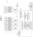
- FIG. 1 is a schematic diagram illustrating a configuration of a furnace temperature control device 20 according to the present embodiment.
- the coke oven 1 illustrated in FIG. 1 includes N combustion chambers 2 (2-1 to 2-N) and N-1 carbonization chambers 3 (3-1 to 3-(N-1)), which are connected alternately to form a furnace group.
- N is an integer equal to or greater than 2 but is not limited to a specific number.
- coal serving as raw material is charged into the carbonization chamber 3, and fuel gas G is supplied to the combustion chamber 2.
- the coke oven 1 produces coke through dry distillation of the coal in the carbonization chamber 3 by heating the carbonization chamber 3 with heat emitted from the combustion chambers 2 on both sides.
- the furnace temperature control device 20 controls the temperature of the combustion chamber 2 or the carbonization chamber 3 in the coke oven 1.
- the coke oven 1 includes a gas main 4 connected at one end to a gas supply source.
- the other end of the gas main 4 is divided into N-1 branches that are piped to the combustion chambers 2 to supply the fuel gas G to the combustion chambers 2.
- a regulating valve 5 is provided at one end of the gas main 4 to regulate the flow rate of the fuel gas G supplied to the entire furnace group (total flow rate of the fuel gas G supplied to the combustion chambers 2).
- Each of the branches at the other end is provided with a furnace-specific regulating valve 6 (6-1 to 6-(N-1)) to finely regulate the distributed gas flow rate for supply to the combustion chambers 2.
- the fuel gas G finely regulated by the 1 st to (N-1) th furnace-specific regulating valves 6 is supplied to the two combustion chambers 2 adjacent to the corresponding 1 st to (N-1) th carbonization chambers 3.
- the opening degree (regulating valve opening degree) of the regulating valve 5 and the furnace-specific regulating valves 6 is controlled by a control terminal 10.
- the furnace temperature control system includes the control terminal 10, the furnace temperature control device 20, and a display apparatus 30 as main components.
- the control terminal 10 is configured by an information processing apparatus such as a personal computer or workstation.
- the control terminal 10 monitors the condition of the combustion chambers 2 and the carbonization chambers 3 and manages the combustion chambers 2 and the carbonization chambers 3 according to the furnace temperature control device 20.
- the control terminal 10 also manages the operation of the coke oven 1. For example, the control terminal 10 regulates the regulating valve opening degree of the regulating valve 5 to control the flow rate of fuel gas G supplied to the entire furnace group so that the average temperature of the combustion chambers 2 and the carbonization chambers 3 in the entire furnace group becomes the target temperature.
- the control terminal 10 manages the operation of the coke oven 1 by regulating the regulating valve opening degree of the furnace-specific regulating valves 6 and controlling the flow rate of the fuel gas G supplied to the combustion chambers 2, so that the temperatures in the combustion chambers 2 and the carbonization chambers 3 become individually set target temperatures.
- the furnace temperature control device 20 is configured by an information processing apparatus such as a personal computer or workstation.
- the furnace temperature control device 20 includes an input apparatus 21, a database 22, a model learning unit 23, a temperature prediction unit 24, a furnace temperature control unit 25, and an output apparatus 26.
- the input apparatus 21 is an interface for input into which various measurement results and actual operation information regarding the coke oven 1 are inputted.
- Examples of the input apparatuses 21 include a keyboard, mouse, pointing device, data receiver, and graphical user interface (GUI).
- GUI graphical user interface
- the input apparatus 21 receives actual operation information, parameter setting values, and the like from an external source, writes the information into the database 22, and transmits the information to the temperature prediction unit 24.
- the input apparatus 21 receives the actual operation information from the control terminal 10.
- the actual operation information includes at least actual values of the temperature of the combustion chamber 2 and the carbonization chamber 3 (temperature measurement results) and actual values of the heat supply to the combustion chamber 2 and the carbonization chamber 3.
- the actual values of the heat supply to the combustion chamber 2 and the carbonization chamber 3 may include the opening degree of the regulating valve 5 and the furnace-specific regulating valves 6.
- the actual operation information may include the flow rate and composition of the fuel gas G supplied to the entire furnace group.
- the actual operation information preferably includes actual values of weight, actual values of moisture content, and actual values of elapsed time from charging.
- the temperature prediction unit 24 calculates the predicted temperature based on the actual operation information for the combustion chamber 2 and the carbonization chamber 3 that are in close proximity in addition to the actual operation information for the combustion chamber 2 or the carbonization chamber 3 that is targeted. Therefore, the actual operation information inputted to the input apparatus 21 includes not only the actual operation information for a specific combustion chamber 2 or carbonization chamber 3, but also the actual operation information for the combustion chambers 2 and carbonization chambers 3 in close proximity. In the present embodiment, when the actual operation information for combustion chamber 2-n, for example, is inputted, the actual operation information for the adjacent carbonization chamber 3-(n-1) and carbonization chamber 3-n are also inputted.
- the actual operation information for the combustion chamber 2-(n-1) and combustion chamber 2-(n+1) in close proximity is also inputted.
- the flow rate and composition of the fuel gas G related to the amount of heat supply to the combustion chamber 2-n may additionally be inputted.
- the opening degree of the regulating valve 5 and the opening degree of the furnace-specific regulating valve 6-(n-1) and the furnace-specific regulating valve 6-n may additionally be inputted.
- the combustion chamber 2 and carbonization chamber 3 in close proximity do not necessarily include both a combustion chamber 2 and a carbonization chamber 3 but may be a plurality of combustion chambers 2 or a plurality of carbonization chambers 3.
- the database 22 is a storage apparatus in which the actual operation information inputted into the input apparatus 21 and the models generated by the model learning unit 23 are stored. Various information inputted into the input apparatus 21 and model equations and parameters calculated by the model learning unit 23 are transmitted to the database 22. The model equations and parameters stored in the database 22 are used by the temperature prediction unit 24.
- the model learning unit 23, temperature prediction unit 24, and furnace temperature control unit 25 are realized by an arithmetic processing unit such as a CPU.
- the model learning unit 23, the temperature prediction unit 24, and the furnace temperature control unit 25 are, for example, realized by execution of computer programs in an arithmetic processing unit.
- the model learning unit 23, the temperature prediction unit 24, and the furnace temperature control unit 25 may have dedicated arithmetic devices or arithmetic circuits.
- the model learning unit 23 generates a model representing the relationship between time-series data of the actual operation information going back a fixed time period from a certain time and the temperature of the combustion chamber 2 or the carbonization chamber 3 after a freely-selected time period from the certain time, based on the actual operation information stored in the database 22.
- a model is generated to predict the temperature of the targeted combustion chamber 2 or carbonization chamber 3 after a freely-selected time period.
- a freely-selected time period in this context means that there are no restrictions on the setting of the future time for predicting the temperature. Since the state of the coke oven 1 changes from moment to moment, there is thought to be a practical limit to the time that can be predicted with sufficient accuracy, depending also on the duration of the time-series data and other factors.
- the model learning unit 23 transmits the generated model equations and their parameters to the database 22.
- the model equations and their parameters are hereinafter referred to as the model.
- the temperature prediction unit 24 calculates the predicted temperature of the combustion chamber 2 or the carbonization chamber 3 after a predetermined time period, which is freely selected at the time of model learning, based on the actual operation information transmitted from the input apparatus 21 and the model stored in the database 22.
- the actual operation information transmitted from the input apparatus 21 may be the most recently measured (latest) actual operation information regarding the combustion chamber 2 or the carbonization chamber 3 that is targeted for calculating the predicted temperature.
- the actual operation information regarding the combustion chamber 2 or carbonization chamber 3 that is targeted includes the actual operation information for the combustion chamber 2 and the carbonization chamber 3 that are in close proximity in addition to the actual operation information for the combustion chamber 2 or the carbonization chamber 3 that is targeted.
- the temperature prediction unit 24 can calculate an accurate predicted temperature by taking into account heat conduction from the combustion chambers 2 and carbonization chambers 3 in close proximity.
- the temperature prediction unit 24 transmits the predicted temperature of the combustion chamber 2 or the carbonization chamber 3 calculated for after the freely-selected predetermined time period to the furnace temperature control unit 25.
- the furnace temperature control unit 25 calculates the heat supply to the combustion chamber 2 or the carbonization chamber 3 to achieve a target temperature, based on the predicted temperature calculated by the temperature prediction unit 24.
- the calculation of the amount of heat supplied to the combustion chamber 2 or the carbonization chamber 3 may be a calculation of the regulating valve opening degree of the regulating valve 5 and the furnace-specific regulating valve 6 to satisfy the required heat supply.
- the furnace temperature control unit 25 transmits the calculated heat supply or regulating valve opening degree to the output apparatus 26.
- the output apparatus 26 transmits the heat supply or the regulating valve opening degree calculated by the furnace temperature control unit 25 to the control terminal 10.
- the control terminal 10 regulates the opening degree of the regulating valve 5 and the furnace-specific regulating valve 6 based on the information transmitted from the output apparatus 26.
- the furnace temperature control device 20 controls the temperature of the combustion chamber 2 or the carbonization chamber 3 in the coke oven 1 via the control terminal 10.
- coke is produced by regulating, based on the heat supply to the combustion chamber 2 or the carbonization chamber 3 calculated by the furnace temperature control device 20, the fuel gas supply to the combustion chamber 2 or the opening degree of the regulating valve that regulates the fuel gas supply.
- the output apparatus 26 also has the function of transmitting the information calculated by the furnace temperature control device 20 to the display apparatus 30 for the display apparatus 30 to display the calculation results outputted from the furnace temperature control device 20.
- the display device 30 is, for example, a liquid crystal display.
- the furnace temperature control device 20 with this configuration accurately controls the temperature of the combustion chamber 2 or the carbonization chamber 3 by executing the furnace temperature control process described below.
- step S1 input step
- the input apparatus 21 acquires the actual operation information.
- the input apparatus 21 transmits the acquired actual operation information to the database 22 and the temperature prediction unit 24.
- the furnace temperature control process then proceeds to step S2.
- step S2 model generation step
- the model learning unit 23 generates a model based on the actual operation information stored in the database 22.
- the process in step S2 may be executed each time actual operation information is acquired by step S1, or when model generation is indicated by a signal inputted from an external source. In other words, the furnace temperature control process may proceed to step S3 without execution of step S2.
- the process in step S2 is not executed, the most recent model generated by the model learning unit 23 and stored in the database 22 may be used.
- step S2 letting the time-series data matrix of the actual operation information, which serves as input to the model to be generated, be X, and the temperature of combustion chamber 2 or carbonization chamber 3 after a freely-selected time period, which serves as the output, be y, the model to be generated can be expressed by Equations (1) and (2) below.
- the X and y subscripts represent time
- t is a freely-selected certain time in the past
- u is a freely-selected time period
- (t+u) is the time for which prediction is to be made
- i is a freely-selected backward time period going back from the certain time t
- j is the number of items in the actual operation information
- f is a function illustrating the relationship between a time-series data matrix of j pieces of the actual operation information from time t going back by i and the temperature of the combustion chamber 2 or the carbonization chamber 3 in the future after u, which is a time period from the certain time t.
- One model input-output data set is created for one time t, but in general, it is known that the more data sets, the better the accuracy of the model for unknown input. Therefore, a data set is preferably created for as many times t as possible.
- the time period u for setting the future time for prediction and the backward time period i are preferably set appropriately according to the time constant or settling time of the response to the temperature change in the combustion chamber 2 or the carbonization chamber 3.
- the time constant or settling time is the time constant or settling time with respect to the heat supply to the combustion chamber 2 or the carbonization chamber 3 or the operation on the regulating valve opening degree.
- the model accuracy may deteriorate, because temperature changes and the like at times prior to i, the backward time period, cannot be taken into consideration.
- the process from charging to extrusion is typically carried out in a fixed cycle for one kiln.
- the temperature to be predicted therefore varies periodically in a steady state, in correspondence with the operation cycle.
- the sum of u and i may be set to a multiple of the period of change (period of variation) of y.
- the prediction error due to periodic changes in the temperature of the target to be predicted can be reduced by setting u and i in this way.
- the number of data points from time t to (t-i), i.e., the number of rows of xt, may be set to the number yielded by dividing i by the input period in a case in which the actual operation information is inputted periodically (discretely at each input period).
- the number of data points from time t to (t-i) may be set to the number yielded by dividing i by the temperature period in a case in which the temperature to be predicted exhibits periodic behavior.
- Feature values, including the average or rate of change of the actual operation information may be calculated and inputted in a case in which the input cycle of the actual operation information is shorter than the data interval from time t to (t-i).
- Linearly interpolated values of the actual operation information may be inputted in a case in which the input cycle of the actual operation information is longer than the data interval from time t to (t-i).
- the inputted actual operation information thus being partitioned by period of change, i.e., by processing the actual operation information into partitions corresponding to periodic changes in the temperature to be predicted, it is possible to reduce the prediction error due to periodic changes in the temperature to be predicted.
- the items of the actual operation information include at least actual values of the temperature of the combustion chamber 2 and the carbonization chamber 3 (temperature measurement results) and actual values of the heat supply to the combustion chamber 2 and the carbonization chamber 3, as described above.
- the actual values of the heat supply to the combustion chamber 2 and the carbonization chamber 3 may include the opening degree of the regulating valve 5 and the furnace-specific regulating valves 6.
- the items of the actual operation information also include actual values for the combustion chamber 2 and carbonization chamber 3 in close proximity.
- the items of the actual operation information may include the flow rate and composition of the fuel gas G supplied to the entire furnace group.
- the items of the actual operation information preferably include actual values of weight, actual values of moisture content, and actual values of elapsed time from charging.
- the function f is preferably a model that can efficiently learn or explain the characteristics of the variation information in the direction of the backward time period i, i.e., the line direction of Xt.
- a regression neural network in which the values of the output layer for the input from the previous time are used as the input layer for the next time, may be used as a method of generating the model.
- Neural networks with convolutional layers for two-dimensional Xt may also be used as a method for generating the model.
- Automatic machine learning logic in which model accuracy is calculated for a plurality of models and the best model is selected, may also be used.
- a method of combining a plurality of models, called ensemble learning may also be used.
- the model learning unit 23 transmits the generated model to the database 22.
- the furnace temperature control process then proceeds to step S3.
- step S3 the temperature prediction unit 24 calculates (predicts) the temperature of the combustion chamber 2 or the carbonization chamber 3 at a future time (t+u) defined during model learning.
- the temperature prediction unit 24 processes the actual operation information acquired by the input apparatus 21 into the same format as Xt above.
- the temperature prediction unit 24 calculates the temperature of the combustion chamber 2 or the carbonization chamber 3 by inputting the processed actual operation information into the model generated by the model learning unit 23.
- the temperature prediction unit 24 preferably selects the model generated by the data set with similar values of the processed actual operation information (x t,1 to x t,j ).
- the temperature prediction unit 24 transmits the temperature of the combustion chamber 2 or the carbonization chamber 3 calculated for the future time to the furnace temperature control unit 25.
- the furnace temperature control process then proceeds to step S4.
- the furnace temperature control unit 25 calculates the heat supply to the combustion chamber 2 or the carbonization chamber 3 to achieve a target temperature, based on the temperature of the combustion chamber 2 or the carbonization chamber 3 calculated by the temperature prediction unit 24.
- the heat supply is determined so as to minimize the difference between the temperature of the combustion chamber 2 or the carbonization chamber 3 (target temperature), which was set for the time of prediction (t+u), and the predicted temperature.
- target temperature the temperature of the combustion chamber 2 or the carbonization chamber 3
- the relationship between the heat supply and the amount of temperature change may be modeled, based on the mass and specific heat of the fuel gas in the combustion chamber 2, the coal in the carbonization chamber 3, and materials related to the furnace wall, and the relationship may be used in the calculation.
- the relationship between the heat supply and the amount of temperature change may be modeled based on the relationship between the change in the heat supply and the change in the temperature of the combustion chamber 2 or the carbonization chamber 3 in past performance data.
- the furnace temperature control unit 25 may calculate the regulating valve opening degree of the regulating valve 5 and the furnace-specific regulating valves 6 to satisfy the required heat supply.
- the relationship between the regulating valve opening degree and the fuel gas flow rate may be modeled based on physical laws and used in the calculation.
- the relationship between the regulating valve opening degree and the change in heat supply or temperature may be modeled based on the relationship between the regulating valve opening degree and the change in heat supply to the combustion chamber 2 or the carbonization chamber 3 or temperature in past performance data.
- the furnace temperature control unit 25 transmits the calculated heat supply or regulating valve opening degree to the output apparatus 26. The furnace temperature control process then proceeds to step S5.
- step S5 the output apparatus 26 transmits the heat supply or the regulating valve opening degree calculated by the furnace temperature control unit 25 to the control terminal 10.
- the control terminal 10 regulates the opening degree of the regulating valve 5 and the furnace-specific regulating valves 6 based on the information transmitted from the output apparatus 26.
- the information calculated by the furnace temperature control device 20 is also transmitted to the display apparatus 30 and displayed on the screen. Therefore, the operator can also regulate the opening degrees of the regulating valve 5 and the furnace-specific regulating valves 6 based on the displayed calculation results. This completes the furnace temperature control process.
- Steps S4 and S5 may also be referred to as the furnace temperature control step.
- the furnace temperature control device 20 the method of controlling furnace temperature, and the method of producing coke according to the present embodiment can predict the temperature after a freely-selected time period with high accuracy using a model that even takes into account a plurality of furnace temperature variation factors and the effects of the combustion chamber 2 and carburization chamber 3 in close proximity. Furnace temperature variations due to continuous variation of a plurality of furnace temperature variation factors in the coke oven 1 can therefore be predicted accurately, enabling highly accurate furnace temperature control.
- the prediction accuracy was evaluated for the case of predicting the temperature of the carbonization chamber 3 using the apparatus and method described in the above embodiment (Example) and the case of predicting the temperature of the carbonization chamber 3 using a conventional prediction method (Conventional Example).
- the time period defining the future time for prediction (the aforementioned u) was 12 hours, and the backward time period (the aforementioned i) was 17 hours.
- the temperatures of the target carbonization chamber 3 and the two adjacent carbonization chambers 3 and the amount of fuel gas supplied to the two combustion chambers 2 adjacent to the target carbonization chamber 3 were used as actual operation information.
- the actual operation information was inputted hourly.
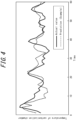
- FIGS. 3 and 4 are plots of actual values vs. predicted values of the temperature of the carbonization chamber 3 after 12 hours. In the Conventional Example in FIG. 3 , there are times when the upper and lower limit variations of the actual values do not match the variations of the predicted values. In the Example in FIG. 4 , the variations in the actual values are accurately tracked and predicted.
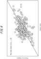
- FIGS. 5 and 6 are diagrams plotting the relationship between actual values and predicted values at each time.
- the error between the actual values and predicted values was large, with a root mean square error of 1.62.
- the error between the actual values and predicted values was small, with a root mean square error of 1.06. It was confirmed that the apparatus and method described in the above embodiment enable highly accurate prediction of future furnace temperature variations, thereby improving the accuracy of furnace temperature control.
Landscapes
- Chemical & Material Sciences (AREA)
- Engineering & Computer Science (AREA)
- Combustion & Propulsion (AREA)
- Physics & Mathematics (AREA)
- General Physics & Mathematics (AREA)
- Automation & Control Theory (AREA)
- Materials Engineering (AREA)
- Oil, Petroleum & Natural Gas (AREA)
- Organic Chemistry (AREA)
- Coke Industry (AREA)
Abstract
Description
- The present disclosure relates to a furnace temperature control device, a method of controlling furnace temperature, and a method of producing coke. The present disclosure relates, in particular, to a furnace temperature control device, a method of controlling furnace temperature, and a method of producing coke in a coke oven in which combustion chambers and carburization chambers are connected alternately to form a furnace group.
- In a coke oven in which combustion chambers and carburization chambers are connected alternately to form a furnace group, coke is produced by dry distillation of coal charged in a carburization chamber with heat from the adjacent combustion chamber. It is important to control the temperature of the combustion chamber or carbonization chamber to the desired temperature in order to achieve stable quality of coke to be produced in the coke oven, increase production efficiency, and cut down on the amount of heat for dry distillation. Because coke ovens have a large heat capacity in the furnace body and a long time constant of response to actions implemented to manipulate the furnace temperature, actions need to be implemented by predicting the future temperature with high accuracy in order to control the temperature of the combustion chamber or carburization chamber with high accuracy. However, the coke oven temperature varies in a complex manner due to numerous variation factors, such as the properties of the coal to be charged, the dry distillation conditions, and the conditions of the adjacent carbonization and combustion chambers, in addition to the fuel gas supply conditions. It has therefore has been difficult to predict the future temperature with high accuracy.
- As a method for predicting the future temperature with high accuracy, Patent Literature (PTL) 1 proposes modeling the behavior of temperature with respect to variation factors for the coke oven temperature as a step response of a first-order delay system that occurs in a time-series at regular intervals.
- To reduce the furnace temperature prediction error due to disturbances and to the uncertainty of the mathematical model for furnace temperature prediction,
PTL 2 proposes a method to improve the accuracy of future temperature prediction by reflecting the furnace temperature prediction error from the previous dry distillation cycle in the furnace temperature prediction calculation at the current time. -
- PTL 1:
JP H6-158050 A - PTL 2:
JP H5-255668 A - Here, in the technology disclosed in
PTL 1, the parameters of the step response model are used after being identified in advance by investigating the furnace temperature variation when furnace temperature variation factors are individually varied. As a result, the accuracy of the model deteriorates for reasons such as long-term changes in furnace conditions. It is also difficult to identify the parameters of the step response model for each furnace temperature variation factor during normal operation because a plurality of furnace temperature variation factors vary continuously during normal coke oven operation. Furthermore, the accuracy of temperature prediction is greatly reduced when the temperature relative to a coke oven temperature variation factor deviates from the behavior of a first-order delay system. - The technology in
PTL 2 improves the accuracy of future temperature prediction by reflecting the furnace temperature prediction error from the previous dry distillation cycle in the furnace temperature prediction calculation at the current time. In general, however, coal properties, the amount of heat supplied, or other furnace temperature variation factors can vary significantly from the previous dry distillation cycle. In this case, it is difficult to explain the errors in the mathematical model for furnace temperature prediction solely by the prediction errors in the previous dry distillation cycle. The prediction accuracy consequently deteriorates. Further taking into consideration the combustion chamber and carbonization chamber in close proximity to the target yields an enormous combination of the variation patterns of the furnace temperature variation factors. It is therefore difficult to take into consideration the combustion chamber and carbonization chamber in close proximity, which makes the prediction accuracy insufficient. - In this way, it has been challenging to predict the future furnace temperature with high accuracy in an environment such that the state of the coke oven changes from moment to moment and a plurality of furnace temperature variation factors vary continuously.
- In light of these circumstances, it is an aim of the present disclosure to provide a furnace temperature control device, a method of controlling furnace temperature, and a method of producing coke that enable highly accurate furnace temperature control by highly accurately predicting the future temperature of the combustion chamber or carburization chamber.
-
- (1) A furnace temperature control device according to an embodiment of the present disclosure is
a furnace temperature control device for controlling a temperature of a combustion chamber or a carbonization chamber in a coke oven in which the combustion chamber and the carbonization chamber are connected alternately to form a furnace group, the furnace temperature control device including:- an input apparatus configured to receive input of actual operation information including at least actual values of the temperature of the combustion chamber and the carbonization chamber and actual values of a heat supply to the combustion chamber and the carbonization chamber;
- a temperature prediction unit configured to calculate a predicted temperature that is the temperature of the combustion chamber or the carbonization chamber after a freely-selected predetermined time period, based on the actual operation information and a model representing a relationship between time-series data of the actual operation information going back a fixed time period from a certain time and the temperature of the combustion chamber or the carbonization chamber after a freely-selected predetermined time period from the certain time; and
- a furnace temperature control unit configured to calculate a heat supply to the combustion chamber or the carbonization chamber to achieve a target temperature, based on the calculated predicted temperature.
- (2) As an embodiment of the present disclosure, in (1),
with regard to coal charged into the carbonization chamber, the actual operation information includes an actual value of weight, an actual value of moisture content, an actual value of elapsed time from charging, and an actual value of an opening degree of a regulating valve that regulates a fuel gas supply to the combustion chamber. - (3) As an embodiment of the present disclosure, in (1) or (2),
the temperature prediction unit is configured to calculate the predicted temperature based on the actual operation information for the combustion chamber and the carbonization chamber that are in close proximity in addition to the actual operation information for the combustion chamber or the carbonization chamber that is targeted for calculating the predicted temperature. - (4) As an embodiment of the present disclosure, in any one of (1) to (3),
the temperature prediction unit is configured to partition time-series data, of the actual operation information going back a longer time period than a period of change of the temperature of the combustion chamber or the carburization chamber from a certain time, by the period of change of the temperature of the combustion chamber or the carburization chamber, and calculate a predicted temperature that is the temperature of the combustion chamber or the carburization chamber after the period of change of the temperature of the carburization chamber based on the actual operation information and a model representing a relationship between feature values of time-series data of the actual operation information for each partition and the temperature of the combustion chamber or the carburization chamber after the period of change of the temperature of the combustion chamber or the carburization chamber from the certain time. - (5) A method of controlling furnace temperature according to an embodiment of the present disclosure is
a method of controlling furnace temperature to control a temperature of a combustion chamber or a carbonization chamber in a coke oven in which the combustion chamber and the carbonization chamber are connected alternately to form a furnace group, the method including:- receiving input of actual operation information including at least actual values of the temperature of the combustion chamber and the carbonization chamber and actual values of a heat supply to the combustion chamber and the carbonization chamber;
- calculating a predicted temperature that is the temperature of the combustion chamber or the carbonization chamber after a freely-selected predetermined time period, based on the actual operation information and a model representing a relationship between time-series data of the actual operation information going back a fixed time period from a certain time and the temperature of the combustion chamber or the carbonization chamber after a freely-selected predetermined time period from the certain time; and
- calculating a heat supply to the combustion chamber or the carbonization chamber to achieve a target temperature, based on the calculated predicted temperature.
- (6) As an embodiment of the present disclosure, in (5),
with regard to coal charged into the carbonization chamber, the actual operation information includes an actual value of weight, an actual value of moisture content, an actual value of elapsed time from charging, and an actual value of an opening degree of a regulating valve that regulates a fuel gas supply to the combustion chamber. - (7) As an embodiment of the present disclosure, in (5) or (6),
the calculating of the predicted temperature includes calculating the predicted temperature based on the actual operation information for the combustion chamber and the carbonization chamber that are in close proximity in addition to the actual operation information for the combustion chamber or the carbonization chamber that is targeted for calculating the predicted temperature. - (8) As an embodiment of the present disclosure, in any one of (5) to (7),
the calculating of the predicted temperature includes partitioning time-series data, of the actual operation information going back a longer time period than a period of change of the temperature of the combustion chamber or the carburization chamber from a certain time, by the period of change of the temperature of the combustion chamber or the carburization chamber, and calculating a predicted temperature that is the temperature of the combustion chamber or the carburization chamber after the period of change of the temperature of the carburization chamber based on the actual operation information and a model representing a relationship between feature values of time-series data of the actual operation information for each partition and the temperature of the combustion chamber or the carburization chamber after the period of change of the temperature of the combustion chamber or the carburization chamber from the certain time. - (9) A method of producing coke according to an embodiment of the present disclosure includes
producing coke by regulating, based on the heat supply to the combustion chamber or the carbonization chamber calculated by the method of controlling furnace temperature according to any one of (5) to (8), a fuel gas supply to the combustion chamber or an opening degree of a regulating valve that regulates the fuel gas supply. - According to the present disclosure, a furnace temperature control device, a method of controlling furnace temperature, and a method of producing coke that enable highly accurate furnace temperature control by highly accurately predicting the future temperature of the combustion chamber or carburization chamber can be provided.
- In the accompanying drawings:
-
FIG. 1 is a schematic diagram illustrating a configuration of a furnace temperature control device according to an embodiment of the present disclosure; -
FIG. 2 is a flowchart illustrating the processing flow in a method of controlling furnace temperature according to an embodiment of the present disclosure; -
FIG. 3 is a plot of actual values vs. predicted values in a Conventional Example; -
FIG. 4 is a plot of actual values vs. predicted values in an Example; -
FIG. 5 is a diagram illustrating the relationship between actual values and predicted values in the Conventional Example; and -
FIG. 6 is a diagram illustrating the relationship between actual values and predicted values in the Example. - A furnace temperature control device, a method of controlling furnace temperature, and a method of producing coke according to an embodiment of the present disclosure will be described below with reference to the drawings.
-
FIG. 1 is a schematic diagram illustrating a configuration of a furnacetemperature control device 20 according to the present embodiment. Thecoke oven 1 illustrated inFIG. 1 includes N combustion chambers 2 (2-1 to 2-N) and N-1 carbonization chambers 3 (3-1 to 3-(N-1)), which are connected alternately to form a furnace group. N is an integer equal to or greater than 2 but is not limited to a specific number. In thecoke oven 1, coal serving as raw material is charged into thecarbonization chamber 3, and fuel gas G is supplied to thecombustion chamber 2. Thecoke oven 1 produces coke through dry distillation of the coal in thecarbonization chamber 3 by heating thecarbonization chamber 3 with heat emitted from thecombustion chambers 2 on both sides. The furnacetemperature control device 20 according to the present embodiment controls the temperature of thecombustion chamber 2 or thecarbonization chamber 3 in thecoke oven 1. - The
coke oven 1 includes a gas main 4 connected at one end to a gas supply source. The other end of the gas main 4 is divided into N-1 branches that are piped to thecombustion chambers 2 to supply the fuel gas G to thecombustion chambers 2. A regulatingvalve 5 is provided at one end of the gas main 4 to regulate the flow rate of the fuel gas G supplied to the entire furnace group (total flow rate of the fuel gas G supplied to the combustion chambers 2). Each of the branches at the other end is provided with a furnace-specific regulating valve 6 (6-1 to 6-(N-1)) to finely regulate the distributed gas flow rate for supply to thecombustion chambers 2. The fuel gas G finely regulated by the 1st to (N-1)th furnace-specific regulating valves 6 is supplied to the twocombustion chambers 2 adjacent to the corresponding 1st to (N-1)thcarbonization chambers 3. The opening degree (regulating valve opening degree) of the regulatingvalve 5 and the furnace-specific regulating valves 6 is controlled by acontrol terminal 10. - The furnace temperature control system includes the
control terminal 10, the furnacetemperature control device 20, and adisplay apparatus 30 as main components. Thecontrol terminal 10 is configured by an information processing apparatus such as a personal computer or workstation. Thecontrol terminal 10 monitors the condition of thecombustion chambers 2 and thecarbonization chambers 3 and manages thecombustion chambers 2 and thecarbonization chambers 3 according to the furnacetemperature control device 20. Thecontrol terminal 10 also manages the operation of thecoke oven 1. For example, thecontrol terminal 10 regulates the regulating valve opening degree of the regulatingvalve 5 to control the flow rate of fuel gas G supplied to the entire furnace group so that the average temperature of thecombustion chambers 2 and thecarbonization chambers 3 in the entire furnace group becomes the target temperature. Thecontrol terminal 10 manages the operation of thecoke oven 1 by regulating the regulating valve opening degree of the furnace-specific regulating valves 6 and controlling the flow rate of the fuel gas G supplied to thecombustion chambers 2, so that the temperatures in thecombustion chambers 2 and thecarbonization chambers 3 become individually set target temperatures. - The furnace
temperature control device 20 is configured by an information processing apparatus such as a personal computer or workstation. The furnacetemperature control device 20 includes aninput apparatus 21, adatabase 22, amodel learning unit 23, atemperature prediction unit 24, a furnacetemperature control unit 25, and anoutput apparatus 26. - The
input apparatus 21 is an interface for input into which various measurement results and actual operation information regarding thecoke oven 1 are inputted. Examples of theinput apparatuses 21 include a keyboard, mouse, pointing device, data receiver, and graphical user interface (GUI). Theinput apparatus 21 receives actual operation information, parameter setting values, and the like from an external source, writes the information into thedatabase 22, and transmits the information to thetemperature prediction unit 24. Theinput apparatus 21 receives the actual operation information from thecontrol terminal 10. The actual operation information includes at least actual values of the temperature of thecombustion chamber 2 and the carbonization chamber 3 (temperature measurement results) and actual values of the heat supply to thecombustion chamber 2 and thecarbonization chamber 3. The actual values of the heat supply to thecombustion chamber 2 and thecarbonization chamber 3 may include the opening degree of the regulatingvalve 5 and the furnace-specific regulating valves 6. The actual operation information may include the flow rate and composition of the fuel gas G supplied to the entire furnace group. With regard to the coal charged into thecarbonization chamber 3, the actual operation information preferably includes actual values of weight, actual values of moisture content, and actual values of elapsed time from charging. - Here, as described below, the
temperature prediction unit 24 calculates the predicted temperature based on the actual operation information for thecombustion chamber 2 and thecarbonization chamber 3 that are in close proximity in addition to the actual operation information for thecombustion chamber 2 or thecarbonization chamber 3 that is targeted. Therefore, the actual operation information inputted to theinput apparatus 21 includes not only the actual operation information for aspecific combustion chamber 2 orcarbonization chamber 3, but also the actual operation information for thecombustion chambers 2 andcarbonization chambers 3 in close proximity. In the present embodiment, when the actual operation information for combustion chamber 2-n, for example, is inputted, the actual operation information for the adjacent carbonization chamber 3-(n-1) and carbonization chamber 3-n are also inputted. Furthermore, the actual operation information for the combustion chamber 2-(n-1) and combustion chamber 2-(n+1) in close proximity is also inputted. The flow rate and composition of the fuel gas G related to the amount of heat supply to the combustion chamber 2-n may additionally be inputted. The opening degree of the regulatingvalve 5 and the opening degree of the furnace-specific regulating valve 6-(n-1) and the furnace-specific regulating valve 6-n may additionally be inputted. Here, thecombustion chamber 2 andcarbonization chamber 3 in close proximity do not necessarily include both acombustion chamber 2 and acarbonization chamber 3 but may be a plurality ofcombustion chambers 2 or a plurality ofcarbonization chambers 3. - The
database 22 is a storage apparatus in which the actual operation information inputted into theinput apparatus 21 and the models generated by themodel learning unit 23 are stored. Various information inputted into theinput apparatus 21 and model equations and parameters calculated by themodel learning unit 23 are transmitted to thedatabase 22. The model equations and parameters stored in thedatabase 22 are used by thetemperature prediction unit 24. - The
model learning unit 23,temperature prediction unit 24, and furnacetemperature control unit 25 are realized by an arithmetic processing unit such as a CPU. Themodel learning unit 23, thetemperature prediction unit 24, and the furnacetemperature control unit 25 are, for example, realized by execution of computer programs in an arithmetic processing unit. Here, as another example, themodel learning unit 23, thetemperature prediction unit 24, and the furnacetemperature control unit 25 may have dedicated arithmetic devices or arithmetic circuits. - The
model learning unit 23 generates a model representing the relationship between time-series data of the actual operation information going back a fixed time period from a certain time and the temperature of thecombustion chamber 2 or thecarbonization chamber 3 after a freely-selected time period from the certain time, based on the actual operation information stored in thedatabase 22. In other words, a model is generated to predict the temperature of the targetedcombustion chamber 2 orcarbonization chamber 3 after a freely-selected time period. A freely-selected time period in this context means that there are no restrictions on the setting of the future time for predicting the temperature. Since the state of thecoke oven 1 changes from moment to moment, there is thought to be a practical limit to the time that can be predicted with sufficient accuracy, depending also on the duration of the time-series data and other factors. No particular setting restrictions or the like based on prediction accuracy, however, are established in the generated model. Therefore, the future time for which the temperature is predicted can be set freely. Themodel learning unit 23 transmits the generated model equations and their parameters to thedatabase 22. The model equations and their parameters are hereinafter referred to as the model. - The
temperature prediction unit 24 calculates the predicted temperature of thecombustion chamber 2 or thecarbonization chamber 3 after a predetermined time period, which is freely selected at the time of model learning, based on the actual operation information transmitted from theinput apparatus 21 and the model stored in thedatabase 22. Here, the actual operation information transmitted from theinput apparatus 21 may be the most recently measured (latest) actual operation information regarding thecombustion chamber 2 or thecarbonization chamber 3 that is targeted for calculating the predicted temperature. As described above, the actual operation information regarding thecombustion chamber 2 orcarbonization chamber 3 that is targeted includes the actual operation information for thecombustion chamber 2 and thecarbonization chamber 3 that are in close proximity in addition to the actual operation information for thecombustion chamber 2 or thecarbonization chamber 3 that is targeted. Thetemperature prediction unit 24 can calculate an accurate predicted temperature by taking into account heat conduction from thecombustion chambers 2 andcarbonization chambers 3 in close proximity. Thetemperature prediction unit 24 transmits the predicted temperature of thecombustion chamber 2 or thecarbonization chamber 3 calculated for after the freely-selected predetermined time period to the furnacetemperature control unit 25. - The furnace
temperature control unit 25 calculates the heat supply to thecombustion chamber 2 or thecarbonization chamber 3 to achieve a target temperature, based on the predicted temperature calculated by thetemperature prediction unit 24. The calculation of the amount of heat supplied to thecombustion chamber 2 or thecarbonization chamber 3 may be a calculation of the regulating valve opening degree of the regulatingvalve 5 and the furnace-specific regulating valve 6 to satisfy the required heat supply. The furnacetemperature control unit 25 transmits the calculated heat supply or regulating valve opening degree to theoutput apparatus 26. - The
output apparatus 26 transmits the heat supply or the regulating valve opening degree calculated by the furnacetemperature control unit 25 to thecontrol terminal 10. Thecontrol terminal 10 regulates the opening degree of the regulatingvalve 5 and the furnace-specific regulating valve 6 based on the information transmitted from theoutput apparatus 26. In this way, the furnacetemperature control device 20 controls the temperature of thecombustion chamber 2 or thecarbonization chamber 3 in thecoke oven 1 via thecontrol terminal 10. In a method of producing coke in thecoke furnace 1, coke is produced by regulating, based on the heat supply to thecombustion chamber 2 or thecarbonization chamber 3 calculated by the furnacetemperature control device 20, the fuel gas supply to thecombustion chamber 2 or the opening degree of the regulating valve that regulates the fuel gas supply. Theoutput apparatus 26 also has the function of transmitting the information calculated by the furnacetemperature control device 20 to thedisplay apparatus 30 for thedisplay apparatus 30 to display the calculation results outputted from the furnacetemperature control device 20. Here, thedisplay device 30 is, for example, a liquid crystal display. - The furnace
temperature control device 20 with this configuration accurately controls the temperature of thecombustion chamber 2 or thecarbonization chamber 3 by executing the furnace temperature control process described below. -
FIG. 2 is a flowchart illustrating the flow of a process, executed by the furnacetemperature control device 20 according to an embodiment of the present disclosure, for a furnace temperature control method (furnace temperature control process). The flowchart illustrated inFIG. 2 may be started at any timing at which the actual operation information is acquired or any timing at which a signal indicating the start of processing is inputted from an external source. - In step S1 (input step), the
input apparatus 21 acquires the actual operation information. Theinput apparatus 21 transmits the acquired actual operation information to thedatabase 22 and thetemperature prediction unit 24. The furnace temperature control process then proceeds to step S2. - In step S2 (model generation step), the
model learning unit 23 generates a model based on the actual operation information stored in thedatabase 22. The process in step S2 may be executed each time actual operation information is acquired by step S1, or when model generation is indicated by a signal inputted from an external source. In other words, the furnace temperature control process may proceed to step S3 without execution of step S2. In a case in which the process in step S2 is not executed, the most recent model generated by themodel learning unit 23 and stored in thedatabase 22 may be used. - In the process in step S2, letting the time-series data matrix of the actual operation information, which serves as input to the model to be generated, be X, and the temperature of
combustion chamber 2 orcarbonization chamber 3 after a freely-selected time period, which serves as the output, be y, the model to be generated can be expressed by Equations (1) and (2) below.

- Here, the X and y subscripts represent time, t is a freely-selected certain time in the past, u is a freely-selected time period, (t+u) is the time for which prediction is to be made, i is a freely-selected backward time period going back from the certain time t, j is the number of items in the actual operation information, and f is a function illustrating the relationship between a time-series data matrix of j pieces of the actual operation information from time t going back by i and the temperature of the
combustion chamber 2 or thecarbonization chamber 3 in the future after u, which is a time period from the certain time t. - One model input-output data set is created for one time t, but in general, it is known that the more data sets, the better the accuracy of the model for unknown input. Therefore, a data set is preferably created for as many times t as possible.
- The time period u for setting the future time for prediction and the backward time period i are preferably set appropriately according to the time constant or settling time of the response to the temperature change in the
combustion chamber 2 or thecarbonization chamber 3. The time constant or settling time is the time constant or settling time with respect to the heat supply to thecombustion chamber 2 or thecarbonization chamber 3 or the operation on the regulating valve opening degree. For example, in a case in which the sum of u and i is extremely shorter than the settling time, the model accuracy may deteriorate, because temperature changes and the like at times prior to i, the backward time period, cannot be taken into consideration. In addition, in a coke oven, the process from charging to extrusion is typically carried out in a fixed cycle for one kiln. The temperature to be predicted therefore varies periodically in a steady state, in correspondence with the operation cycle. In a case in which y, the temperature to be predicted, exhibits periodic behavior, the sum of u and i may be set to a multiple of the period of change (period of variation) of y. The prediction error due to periodic changes in the temperature of the target to be predicted can be reduced by setting u and i in this way. - It suffices for the number of data points from time t to (t-i), i.e., the number of rows of xt, to be set to the number yielded by dividing i by the input period in a case in which the actual operation information is inputted periodically (discretely at each input period). The number of data points from time t to (t-i) may be set to the number yielded by dividing i by the temperature period in a case in which the temperature to be predicted exhibits periodic behavior. Feature values, including the average or rate of change of the actual operation information, may be calculated and inputted in a case in which the input cycle of the actual operation information is shorter than the data interval from time t to (t-i). Linearly interpolated values of the actual operation information may be inputted in a case in which the input cycle of the actual operation information is longer than the data interval from time t to (t-i). By the inputted actual operation information thus being partitioned by period of change, i.e., by processing the actual operation information into partitions corresponding to periodic changes in the temperature to be predicted, it is possible to reduce the prediction error due to periodic changes in the temperature to be predicted.
- In relation to the aforementioned j, the items of the actual operation information include at least actual values of the temperature of the
combustion chamber 2 and the carbonization chamber 3 (temperature measurement results) and actual values of the heat supply to thecombustion chamber 2 and thecarbonization chamber 3, as described above. The actual values of the heat supply to thecombustion chamber 2 and thecarbonization chamber 3 may include the opening degree of the regulatingvalve 5 and the furnace-specific regulating valves 6. The items of the actual operation information also include actual values for thecombustion chamber 2 andcarbonization chamber 3 in close proximity. The items of the actual operation information may include the flow rate and composition of the fuel gas G supplied to the entire furnace group. Also, with regard to the coal charged into thecarbonization chamber 3, the items of the actual operation information preferably include actual values of weight, actual values of moisture content, and actual values of elapsed time from charging. - The function f is preferably a model that can efficiently learn or explain the characteristics of the variation information in the direction of the backward time period i, i.e., the line direction of Xt. For example, a regression neural network, in which the values of the output layer for the input from the previous time are used as the input layer for the next time, may be used as a method of generating the model. Neural networks with convolutional layers for two-dimensional Xt may also be used as a method for generating the model. Automatic machine learning logic, in which model accuracy is calculated for a plurality of models and the best model is selected, may also be used. A method of combining a plurality of models, called ensemble learning, may also be used.
- The
model learning unit 23 transmits the generated model to thedatabase 22. The furnace temperature control process then proceeds to step S3. - In step S3 (temperature prediction step), the
temperature prediction unit 24 calculates (predicts) the temperature of thecombustion chamber 2 or thecarbonization chamber 3 at a future time (t+u) defined during model learning. Thetemperature prediction unit 24 processes the actual operation information acquired by theinput apparatus 21 into the same format as Xt above. Thetemperature prediction unit 24 calculates the temperature of thecombustion chamber 2 or thecarbonization chamber 3 by inputting the processed actual operation information into the model generated by themodel learning unit 23. Here, in a case in which a plurality of models is generated, thetemperature prediction unit 24 preferably selects the model generated by the data set with similar values of the processed actual operation information (xt,1 to xt,j). Thetemperature prediction unit 24 transmits the temperature of thecombustion chamber 2 or thecarbonization chamber 3 calculated for the future time to the furnacetemperature control unit 25. The furnace temperature control process then proceeds to step S4. - In the process in step S4, the furnace
temperature control unit 25 calculates the heat supply to thecombustion chamber 2 or thecarbonization chamber 3 to achieve a target temperature, based on the temperature of thecombustion chamber 2 or thecarbonization chamber 3 calculated by thetemperature prediction unit 24. The heat supply is determined so as to minimize the difference between the temperature of thecombustion chamber 2 or the carbonization chamber 3 (target temperature), which was set for the time of prediction (t+u), and the predicted temperature. Here, for further accuracy, the relationship between the heat supply and the amount of temperature change may be modeled, based on the mass and specific heat of the fuel gas in thecombustion chamber 2, the coal in thecarbonization chamber 3, and materials related to the furnace wall, and the relationship may be used in the calculation. The relationship between the heat supply and the amount of temperature change may be modeled based on the relationship between the change in the heat supply and the change in the temperature of thecombustion chamber 2 or thecarbonization chamber 3 in past performance data. - The furnace
temperature control unit 25 may calculate the regulating valve opening degree of the regulatingvalve 5 and the furnace-specific regulating valves 6 to satisfy the required heat supply. Here, for further accuracy, the relationship between the regulating valve opening degree and the fuel gas flow rate may be modeled based on physical laws and used in the calculation. The relationship between the regulating valve opening degree and the change in heat supply or temperature may be modeled based on the relationship between the regulating valve opening degree and the change in heat supply to thecombustion chamber 2 or thecarbonization chamber 3 or temperature in past performance data. The furnacetemperature control unit 25 transmits the calculated heat supply or regulating valve opening degree to theoutput apparatus 26. The furnace temperature control process then proceeds to step S5. - In the process in step S5, the
output apparatus 26 transmits the heat supply or the regulating valve opening degree calculated by the furnacetemperature control unit 25 to thecontrol terminal 10. Thecontrol terminal 10 regulates the opening degree of the regulatingvalve 5 and the furnace-specific regulating valves 6 based on the information transmitted from theoutput apparatus 26. The information calculated by the furnacetemperature control device 20 is also transmitted to thedisplay apparatus 30 and displayed on the screen. Therefore, the operator can also regulate the opening degrees of the regulatingvalve 5 and the furnace-specific regulating valves 6 based on the displayed calculation results. This completes the furnace temperature control process. Steps S4 and S5 may also be referred to as the furnace temperature control step. - As described above, the furnace
temperature control device 20, the method of controlling furnace temperature, and the method of producing coke according to the present embodiment can predict the temperature after a freely-selected time period with high accuracy using a model that even takes into account a plurality of furnace temperature variation factors and the effects of thecombustion chamber 2 andcarburization chamber 3 in close proximity. Furnace temperature variations due to continuous variation of a plurality of furnace temperature variation factors in thecoke oven 1 can therefore be predicted accurately, enabling highly accurate furnace temperature control. - The effects of the present disclosure will be described in detail below based on examples, but the present disclosure is not limited to the content of the examples.
- The prediction accuracy was evaluated for the case of predicting the temperature of the
carbonization chamber 3 using the apparatus and method described in the above embodiment (Example) and the case of predicting the temperature of thecarbonization chamber 3 using a conventional prediction method (Conventional Example). In the example (Example), the time period defining the future time for prediction (the aforementioned u) was 12 hours, and the backward time period (the aforementioned i) was 17 hours. The temperatures of thetarget carbonization chamber 3 and the twoadjacent carbonization chambers 3 and the amount of fuel gas supplied to the twocombustion chambers 2 adjacent to thetarget carbonization chamber 3 were used as actual operation information. The actual operation information was inputted hourly. A regression neural network model with long-term and short-term memory structures in the intermediate layers was used as the model for the Example. In the Conventional Example, a model was used to predict the temperature of thetarget carbonization chamber 3 after 12 hours based on 17 hours worth of past rates of change for the temperature of thecarbonization chamber 3.FIGS. 3 and4 are plots of actual values vs. predicted values of the temperature of thecarbonization chamber 3 after 12 hours. In the Conventional Example inFIG. 3 , there are times when the upper and lower limit variations of the actual values do not match the variations of the predicted values. In the Example inFIG. 4 , the variations in the actual values are accurately tracked and predicted. -
FIGS. 5 and6 are diagrams plotting the relationship between actual values and predicted values at each time. In the Conventional Example inFIG. 5 , the error between the actual values and predicted values was large, with a root mean square error of 1.62. In the example inFIG. 6 , the error between the actual values and predicted values was small, with a root mean square error of 1.06. It was confirmed that the apparatus and method described in the above embodiment enable highly accurate prediction of future furnace temperature variations, thereby improving the accuracy of furnace temperature control. - While embodiments of the present disclosure have been described with reference to the drawings and examples, it should be noted that various modifications and amendments may easily be implemented by those skilled in the art based on the present disclosure. Accordingly, such modifications and amendments are included within the scope of the present disclosure. For example, functions or the like included in each component, each step, or the like can be rearranged without logical inconsistency, and a plurality of components, steps, or the like can be combined into one or divided. Embodiments according to the present disclosure can also be realized as a program executed by a processor included in an apparatus or as a storage medium having the program recorded thereon. Such embodiments are also to be understood as included in the scope of the present disclosure.
-
- 1
- Coke oven
- 2
- Combustion chamber
- 3
- Carbonization chamber
- 4
- Gas main
- 5
- Regulating valve
- 6
- Furnace-specific regulating valve
- 10
- Control terminal
- 20
- Furnace temperature control device
- 21
- Input apparatus
- 22
- Database
- 23
- Model learning unit
- 24
- Temperature prediction unit
- 25
- Furnace temperature control unit
- 26
- Output apparatus
- 30
- Display apparatus
Claims (9)
- A furnace temperature control device for controlling a temperature of a combustion chamber or a carbonization chamber in a coke oven in which the combustion chamber and the carbonization chamber are connected alternately to form a furnace group, the furnace temperature control device comprising:an input apparatus configured to receive input of actual operation information including at least actual values of the temperature of the combustion chamber and the carbonization chamber and actual values of a heat supply to the combustion chamber and the carbonization chamber;a temperature prediction unit configured to calculate a predicted temperature that is the temperature of the combustion chamber or the carbonization chamber after a freely-selected predetermined time period, based on the actual operation information and a model representing a relationship between time-series data of the actual operation information going back a fixed time period from a certain time and the temperature of the combustion chamber or the carbonization chamber after a freely-selected predetermined time period from the certain time; anda furnace temperature control unit configured to calculate a heat supply to the combustion chamber or the carbonization chamber to achieve a target temperature, based on the calculated predicted temperature.
- The furnace temperature control device according to claim 1, wherein with regard to coal charged into the carbonization chamber, the actual operation information includes an actual value of weight, an actual value of moisture content, an actual value of elapsed time from charging, and an actual value of an opening degree of a regulating valve that regulates a fuel gas supply to the combustion chamber.
- The furnace temperature control device according to claim 1 or 2, wherein the temperature prediction unit is configured to calculate the predicted temperature based on the actual operation information for the combustion chamber and the carbonization chamber that are in close proximity in addition to the actual operation information for the combustion chamber or the carbonization chamber that is targeted for calculating the predicted temperature.
- The furnace temperature control device according to any one of claims 1 to 3, wherein the temperature prediction unit is configured to partition time-series data, of the actual operation information going back a longer time period than a period of change of the temperature of the combustion chamber or the carburization chamber from a certain time, by the period of change of the temperature of the combustion chamber or the carburization chamber, and calculate a predicted temperature that is the temperature of the combustion chamber or the carburization chamber after the period of change of the temperature of the carburization chamber based on the actual operation information and a model representing a relationship between feature values of time-series data of the actual operation information for each partition and the temperature of the combustion chamber or the carburization chamber after the period of change of the temperature of the combustion chamber or the carburization chamber from the certain time.
- A method of controlling furnace temperature to control a temperature of a combustion chamber or a carbonization chamber in a coke oven in which the combustion chamber and the carbonization chamber are connected alternately to form a furnace group, the method comprising:receiving input of actual operation information including at least actual values of the temperature of the combustion chamber and the carbonization chamber and actual values of a heat supply to the combustion chamber and the carbonization chamber;calculating a predicted temperature that is the temperature of the combustion chamber or the carbonization chamber after a freely-selected predetermined time period, based on the actual operation information and a model representing a relationship between time-series data of the actual operation information going back a fixed time period from a certain time and the temperature of the combustion chamber or the carbonization chamber after a freely-selected predetermined time period from the certain time; andcalculating a heat supply to the combustion chamber or the carbonization chamber to achieve a target temperature, based on the calculated predicted temperature.
- The method of controlling furnace temperature according to claim 5, wherein with regard to coal charged into the carbonization chamber, the actual operation information includes an actual value of weight, an actual value of moisture content, an actual value of elapsed time from charging, and an actual value of an opening degree of a regulating valve that regulates a fuel gas supply to the combustion chamber.
- The method of controlling furnace temperature according to claim 5 or 6, wherein the calculating of the predicted temperature includes calculating the predicted temperature based on the actual operation information for the combustion chamber and the carbonization chamber that are in close proximity in addition to the actual operation information for the combustion chamber or the carbonization chamber that is targeted for calculating the predicted temperature.
- The method of controlling furnace temperature according to any one of claims 5 to 7, wherein the calculating of the predicted temperature includes partitioning time-series data, of the actual operation information going back a longer time period than a period of change of the temperature of the combustion chamber or the carburization chamber from a certain time, by the period of change of the temperature of the combustion chamber or the carburization chamber, and calculating a predicted temperature that is the temperature of the combustion chamber or the carburization chamber after the period of change of the temperature of the carburization chamber based on the actual operation information and a model representing a relationship between feature values of time-series data of the actual operation information for each partition and the temperature of the combustion chamber or the carburization chamber after the period of change of the temperature of the combustion chamber or the carburization chamber from the certain time.
- A method of producing coke, the method comprising producing coke by regulating, based on the heat supply to the combustion chamber or the carbonization chamber calculated by the method of controlling furnace temperature according to any one of claims 5 to 8, a fuel gas supply to the combustion chamber or an opening degree of a regulating valve that regulates the fuel gas supply.
Applications Claiming Priority (2)
| Application Number | Priority Date | Filing Date | Title |
|---|---|---|---|
| JP2022118286 | 2022-07-25 | ||
| PCT/JP2023/027073 WO2024024752A1 (en) | 2022-07-25 | 2023-07-24 | Furnace temperature control device, furnace temperature control method, and coke manufacturing method |
Publications (2)
| Publication Number | Publication Date |
|---|---|
| EP4502110A1 true EP4502110A1 (en) | 2025-02-05 |
| EP4502110A4 EP4502110A4 (en) | 2025-07-30 |
Family
ID=89451909
Family Applications (1)
| Application Number | Title | Priority Date | Filing Date |
|---|---|---|---|
| EP23846482.0A Pending EP4502110A4 (en) | 2022-07-25 | 2023-07-24 | Furnace temperature control device, furnace temperature control method, and coke manufacturing method |
Country Status (2)
| Country | Link |
|---|---|
| EP (1) | EP4502110A4 (en) |
| JP (1) | JP7409580B1 (en) |
Family Cites Families (6)
| Publication number | Priority date | Publication date | Assignee | Title |
|---|---|---|---|---|
| JPS61141787A (en) * | 1984-12-13 | 1986-06-28 | Kawasaki Steel Corp | Control of oven temperature in coke oven |
| JPH03265685A (en) * | 1990-03-14 | 1991-11-26 | Nippon Steel Corp | Method for controlling temperature of each chamber of coke oven |
| JP2564443B2 (en) * | 1992-03-17 | 1996-12-18 | 新日本製鐵株式会社 | Coke oven furnace temperature control method |
| JPH06158050A (en) * | 1992-11-19 | 1994-06-07 | Osaka Gas Co Ltd | Method for controlling coke oven temperature |
| JPH1180737A (en) * | 1997-08-29 | 1999-03-26 | Nkk Corp | Combustion control method and combustion control device for coke oven |
| KR101300176B1 (en) * | 2011-09-22 | 2013-08-26 | 주식회사 포스코 | Control System Of Input Quantity Of Heat For Coke Oven And Method Thereof |
-
2023
- 2023-07-24 JP JP2023559848A patent/JP7409580B1/en active Active
- 2023-07-24 EP EP23846482.0A patent/EP4502110A4/en active Pending
Also Published As
| Publication number | Publication date |
|---|---|
| JP7409580B1 (en) | 2024-01-09 |
| EP4502110A4 (en) | 2025-07-30 |
| JPWO2024024752A1 (en) | 2024-02-01 |
Similar Documents
| Publication | Publication Date | Title |
|---|---|---|
| WO2024024752A1 (en) | Furnace temperature control device, furnace temperature control method, and coke manufacturing method | |
| CN103605325B (en) | Based on the industrial ethylene pyrolysis furnace complete period dynamic optimization method of agent model | |
| US20230027989A1 (en) | Analysis method that analyses chemical reactions from starting materials, analysis apparatus, analysis system, and analysis program | |
| Xiong et al. | Neural network model-based on-line re-optimisation control of fed-batch processes using a modified iterative dynamic programming algorithm | |
| CN111158237A (en) | Multi-step predictive control method for furnace temperature of industrial furnace based on neural network | |
| JP2018055169A (en) | State prediction device | |
| JP7817550B2 (en) | Control device, method and program | |
| CN117170334B (en) | Intelligent control method and system for rapid drug fusion | |
| CN111133390A (en) | Factory management system and management device | |
| CN118333785A (en) | Method and system for automatically generating production plan of heat treatment furnace | |
| Shi et al. | Stgnets: a spatial–temporal graph neural network for energy consumption prediction in cement industrial manufacturing processes | |
| Sildir et al. | Economic model predictive control of an industrial fluid catalytic cracker | |
| CN114127729B (en) | Predicting coking and scaling progression to improve production plans in chemical production plants | |
| JP7409580B1 (en) | Furnace temperature control device, furnace temperature control method, and coke manufacturing method | |
| US20230143324A1 (en) | System And Method for Determining Cleaning Schedules For Heat Exchangers And Fired Heaters Based On Engineering First Principles And Statistical Modelling | |
| WO2018042337A1 (en) | Olefin plant optimization using steady-state models | |
| BR112024025073B1 (en) | Oven temperature control device, oven temperature control method, and coke production method. | |
| JP2014071859A (en) | Result prediction method and result prediction device | |
| US20250044755A1 (en) | Apparatus for controlling a process for producing a product | |
| CN119647304A (en) | Method and device for determining temperature field distribution in coke drum reactor | |
| CN121165849B (en) | Temperature adjusting method and system for carburant drying equipment | |
| Santander et al. | Deep learning economic model predictive control for refinery operation: A fluid catalytic cracker-fractionator case study | |
| WO2026094568A1 (en) | Furnace temperature control device, furnace temperature control method, and coke manufacturing method | |
| JP7758920B2 (en) | Coke manufacturing process control device, method and program | |
| Grega et al. | Modelling of the glass melting process for real-time implementation |
Legal Events
| Date | Code | Title | Description |
|---|---|---|---|
| STAA | Information on the status of an ep patent application or granted ep patent |
Free format text: STATUS: THE INTERNATIONAL PUBLICATION HAS BEEN MADE |
|
| PUAI | Public reference made under article 153(3) epc to a published international application that has entered the european phase |
Free format text: ORIGINAL CODE: 0009012 |
|
| STAA | Information on the status of an ep patent application or granted ep patent |
Free format text: STATUS: REQUEST FOR EXAMINATION WAS MADE |
|
| 17P | Request for examination filed |
Effective date: 20241029 |
|
| AK | Designated contracting states |
Kind code of ref document: A1 Designated state(s): AL AT BE BG CH CY CZ DE DK EE ES FI FR GB GR HR HU IE IS IT LI LT LU LV MC ME MK MT NL NO PL PT RO RS SE SI SK SM TR |
|
| A4 | Supplementary search report drawn up and despatched |
Effective date: 20250627 |
|
| RIC1 | Information provided on ipc code assigned before grant |
Ipc: C10B 21/10 20060101AFI20250623BHEP Ipc: G05D 23/19 20060101ALI20250623BHEP |
|
| DAV | Request for validation of the european patent (deleted) | ||
| DAX | Request for extension of the european patent (deleted) | ||
| GRAP | Despatch of communication of intention to grant a patent |
Free format text: ORIGINAL CODE: EPIDOSNIGR1 |
|
| STAA | Information on the status of an ep patent application or granted ep patent |
Free format text: STATUS: GRANT OF PATENT IS INTENDED |