EP4501823A1 - Support unit for a denesting apparatus - Google Patents
Support unit for a denesting apparatus Download PDFInfo
- Publication number
- EP4501823A1 EP4501823A1 EP23382796.3A EP23382796A EP4501823A1 EP 4501823 A1 EP4501823 A1 EP 4501823A1 EP 23382796 A EP23382796 A EP 23382796A EP 4501823 A1 EP4501823 A1 EP 4501823A1
- Authority
- EP
- European Patent Office
- Prior art keywords
- support unit
- receptacles
- unit according
- engagement
- stack
- Prior art date
- Legal status (The legal status is an assumption and is not a legal conclusion. Google has not performed a legal analysis and makes no representation as to the accuracy of the status listed.)
- Pending
Links
Images


Classifications
-
- B—PERFORMING OPERATIONS; TRANSPORTING
- B65—CONVEYING; PACKING; STORING; HANDLING THIN OR FILAMENTARY MATERIAL
- B65G—TRANSPORT OR STORAGE DEVICES, e.g. CONVEYORS FOR LOADING OR TIPPING, SHOP CONVEYOR SYSTEMS OR PNEUMATIC TUBE CONVEYORS
- B65G59/00—De-stacking of articles
- B65G59/10—De-stacking nested articles
Definitions
- the present disclosure is related to a denesting apparatus, in particular to a support unit constituting part of a denesting apparatus.
- patent application EP3744666 discloses a stacking device for stacking trays from a stack of trays comprising a vertical guide for receiving a stack of trays, a separating device which is configured for the individual destacking of the respective bottom tray of a tray stack received in the vertical guide and a relief device with a holding element and a drive device, which is configured to move the holding element between a holding position in which the holding element is part of a stack of trays accommodated in the vertical guide, and to move to a release position in which the holding element releases the stack of trays, characterized in that the path of travel of the holding element between the holding position and the release position is defined by a link guide or by a wedge guide.
- Patent application WO20169165 discloses a support unit, constituting part of a denesting apparatus, said support unit supporting a stack of trays, cups or other receptacles to be denested in the denesting apparatus, such that trays, cups or other receptacles are dispensed one by one from a lower part of the stack, where said support unit comprises two vertical guides arranged in close proximity to the stack on opposing sides of said stack, and where on each vertical guide two or more engagement pads are provided, which engagement pads are suitable to simultaneously contact a plurality of edges of the trays, cups or other receptacles to be denested, in a sequential manner, such that at least one engagement pad on either side is in contact with a plurality of edges of the trays, cups or other receptacles to be denested at a time.
- the engagement pads are advantageously provided with a resilient layer such that the resilient pad upon contact with the edge is slightly deformed and thereby handles the edge of the tray and thereby the tray itself in a gentle manner.
- the surface of the engagement pads intended for engagement with the stack of trays, cups or other receptacles to be denested is shaped corresponding to the edge of the trays, cups or other receptacles to be denested.
- Patent application US2019023503A1 discloses a part feeding apparatus comprising: a guide to guide stacked parts stacked in a height direction along a height of the part feeding apparatus; a separator configured to pick up a bottommost part located at a bottom of the stacked parts in the height direction; and a lift mechanism configured to lift the stacked parts except for at least the bottommost part.
- pinching claws might be provided.
- the pinching claws may include an uneven shape on a contact surface with the lid, the material of the pinching claw not especially limited, being, for example, a rubber material, a resin material or a metal material.
- the present disclosure attempts to solve the problems above mentioned.
- a support unit constituting part of a denesting apparatus, that includes includes a frame defining a storage space, the storage space configured to host a stack of receptacles to be denested in the denesting apparatus along a stacking axis; the frame including at least one engagement pad in each of two opposed sides of the frame; each engagement pad including a support surface parallel to the stacking axis, facing the storage space and adjacent thereto, and an engagement portion protruding from the support surface within the storage space, so that the engagement pad is suitable to contact a plurality of edges of receptacles of the stack of receptacles by the engagement portion, characterized in that the engagement portion is composed of an elastomeric material, and the engagement portion is a matrix of protruding flexible pins.
- two engagement pads may be provided in each of the opposed sides of the frame.
- the engagement pad in the support unit may be configured to simultaneously contact at least two of the edges of the receptacles to be denested.
- the engagement pad as disclosed herein may be composed of an elastomeric material.
- the elastomeric material may preferably be a silicone, more preferably platinum cured silicone.
- the elastomeric material may have a Shore A hardness of between 20 and 80, more preferably between 30 and 60.
- the flexible pins as disclosed in the present disclosure may be preferably cylindrical or conical. Other geometries are envisaged, such as that of a prism.
- the matrix of protruding flexible pins may have a density of between 10 and 30 protruding flexible pins per cm 2 .
- the support surface of the engagement pad has preferably a surface of between 5 and 30 cm 2 .
- the support surface may preferentially have a rectangular shape, but other shapes such as circular or oval may also be applied.
- the protruding flexible pins are preferably disposed in aligned rows in the matrix.
- the matrix of protruding flexible pins preferably comprises at least two rows of flexible protruding pins.
- the stacking axis in the support unit is vertical.
- the stacking axis is not vertical, but tilted.
- An angle of up to 30° with respect to the vertical configuration is also disclosed herein.
- the present disclosure is related to a denesting apparatus comprising the support unit as disclosed herein.
- the present disclosure is related to a method to denest a stack of receptacles comprising the support unit as disclosed herein.
- the terms "denesting apparatus”, “tray denester” or “tray denesting apparatus” are equivalent and refer to an apparatus configured to denest receptacles, typically trays.
- receptacle is a generic term that includes, among other containers, trays and cups.
- a receptacle is a container that can be stacked.
- pin refers to a filament-like or a thread-like element. This element preferably has a length-to-diameter ratio of about the same order of magnitude.
- the support unit 1 is a constituting part of a denesting apparauts and comprises a frame 2 that defines a storage space configured to host a stack of repectacles along a stacking axis S.
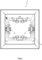
- the frame 2 includes, in this particular embodiment shown in both FIG. 1 and FIG.2 , two engagement pads 3 facing the storage space and adjacent thereto, i.e., a total of four engagement pads 3.
- one engagement pad 3 in each of the two opposing sides of the frame 2 facing the storage space are enough to correctly support their support function.
- the support unit 1 as disclosed in the present invention comprise all the elements needed so that the receptacles in the stack of receptacles are individually denested.
- FIG. 3 shows an embodiment of the engagement pad as disclosed in the present invention.
- the engagement pad 3 includes a support surface 31 parallel to the stacking axis S and an engagement portion 32 protruding from the support surface 31.
- the engagement portion 32 protrudes within the storage space, so that the engagement pad 3 may contact a plurality of edges of receptacles in the stack receptacles by the engagement portion 32.
- the engagement portion 32 is a matrix of protruding flexible pins 320. In the particular embodiment shown in FIG. 3 , the protruding flexible pins 320 are cylindrical.
- the engagement pads 3 have the advantage of adapting to any type of receptacle stacks, independently of their material, the separation between receptacles and the irregularities of the edges of the receptacles, provided that the engagement portion 32 of the pads are composed of an elastomeric material and is a matrix of protruding flexible pins 320.
- the inventors have found that an engagement portion 32 made of a non-elastomeric material increases the errors in the process of denesting a stack of receptacles. These errors may include denesting more than one receptacle at a time,
- the protruding flexible pins 320 have the ability of completely adapting to the geometry of the stack of receptacles, without being prejudicial the material of the receptacles (plastic, cardboard, etc.), the thickness of the receptacles, the distance between receptacles, the evenness of the distance between receptacles, and/or the irregularities of the edges of the receptacles.
- the geometry of the flexible protruding pins 320 is preferably cylindrical, but other geometries are envisaged, such as conical, prism or any other.
- the flexible protruding pins 320 are configured to be adaptable to the stack of receptacles.
- the protruding flexible pins 320 in the matrix of the engagement pad 3 are preferably aligned in rows. There might be an offset between consecutive rows.
- the hardness of the elastomeric material in the engagement portion 32 can be tuned. The higher the hardness, less reactivity and adaptability of the protruding flexible pins 320. Therefore, a Shore A hardness of between 20 and 80 is preferred, being between 30 and 60 more preferred. However, a high hardness of the protruding flexible pins 320 can be compensated by decreasing the diameter and/or the section of the protruding flexible pins 320 to achieve optimum denesting results.
- Two rows of protruding flexible pins 320 in the matrix of the engagement portion 32 are needed to properly perform the support function in a denesting apparatus according to the present disclosure.
Landscapes
- Buffer Packaging (AREA)
Abstract
The present invention discloses a support unit (1), constituting part of a denesting apparatus, including a frame (2) defining a storage space, the storage space configured to host a stack of receptacles to be denested in the denesting apparatus along a stacking axis (S); the frame (2) including at least one engagement pad (3) in each of two opposed sides of the frame; each engagement pad (3) including a support surface (31) parallel to the stacking axis (S), facing the storage space and adjacent thereto, and an engagement portion (32) protruding from the support surface (31) within the storage space, so that the engagement pad (3) is suitable to contact a plurality of edges of receptacles of the stack of receptacles by the engagement portion (32), characterized in that the engagement portion (32) is composed of an elastomeric material, and the engagement portion (32) is a matrix of protruding flexible pins (320).
Description
- The present disclosure is related to a denesting apparatus, in particular to a support unit constituting part of a denesting apparatus.
- Currently, a wide variety of foodstuff is made available to the consumer being deposited in trays. During filling of the trays in an industrial installation, the trays are inserted/loaded into a denesting apparatus which will dispend trays onto a conveyor belt after which the empty trays are transported to a filling station, filled with the desired content and finally sealed, labelled and removed from the production facility. Trays are usually arranged in a denesting apparatus where a stack of trays are rapidly dispensed from the bottom of the stack onto the conveyor belt such that gravity will aid in the dispensing of trays.
- In the industry, several solutions have been provided to conveniently support and individually dispense the trays from the corresponding stack.
- For instance, patent application
EP3744666 discloses a stacking device for stacking trays from a stack of trays comprising a vertical guide for receiving a stack of trays, a separating device which is configured for the individual destacking of the respective bottom tray of a tray stack received in the vertical guide and a relief device with a holding element and a drive device, which is configured to move the holding element between a holding position in which the holding element is part of a stack of trays accommodated in the vertical guide, and to move to a release position in which the holding element releases the stack of trays, characterized in that the path of travel of the holding element between the holding position and the release position is defined by a link guide or by a wedge guide. - Patent application
WO20169165 - Patent application
US2019023503A1 discloses a part feeding apparatus comprising: a guide to guide stacked parts stacked in a height direction along a height of the part feeding apparatus; a separator configured to pick up a bottommost part located at a bottom of the stacked parts in the height direction; and a lift mechanism configured to lift the stacked parts except for at least the bottommost part. To support the lids of the remaining claws, pinching claws might be provided. The pinching claws may include an uneven shape on a contact surface with the lid, the material of the pinching claw not especially limited, being, for example, a rubber material, a resin material or a metal material. - However, there are many aspects to the denesting of trays which need to be addressed and have not been completely solved in the prior art. First, the development of trays is towards trays made from an ever thinner material and the distance between each tray in a stack is ever decreasing. Second, the distance between trays in a stack is usually not even. Third, the edge of the trays are not perfectly even. Fourth, the larger the stack of trays is, the more difficult for the stack to be aligned. These at least four aspects makes tray denesting a challenge, in particular with regards to the optimal support of the trays that leads to an optimal individual denesting of them.
- The present disclosure attempts to solve the problems above mentioned.
- In order to address one or more of the foregoing problems, one aspect of the present disclosure relates to a support unit, constituting part of a denesting apparatus, that includes includes a frame defining a storage space, the storage space configured to host a stack of receptacles to be denested in the denesting apparatus along a stacking axis; the frame including at least one engagement pad in each of two opposed sides of the frame; each engagement pad including a support surface parallel to the stacking axis, facing the storage space and adjacent thereto, and an engagement portion protruding from the support surface within the storage space, so that the engagement pad is suitable to contact a plurality of edges of receptacles of the stack of receptacles by the engagement portion, characterized in that the engagement portion is composed of an elastomeric material, and the engagement portion is a matrix of protruding flexible pins.
- In the support unit as disclosed herein, two engagement pads may be provided in each of the opposed sides of the frame.
- The engagement pad in the support unit may be configured to simultaneously contact at least two of the edges of the receptacles to be denested.
- Moreover, the engagement pad as disclosed herein may be composed of an elastomeric material. The elastomeric material may preferably be a silicone, more preferably platinum cured silicone. In addition, the elastomeric material may have a Shore A hardness of between 20 and 80, more preferably between 30 and 60.
- The flexible pins as disclosed in the present disclosure may be preferably cylindrical or conical. Other geometries are envisaged, such as that of a prism.
- Moreover, the matrix of protruding flexible pins may have a density of between 10 and 30 protruding flexible pins per cm2.
- Moreover, the support surface of the engagement pad has preferably a surface of between 5 and 30 cm2. The support surface may preferentially have a rectangular shape, but other shapes such as circular or oval may also be applied.
- The protruding flexible pins are preferably disposed in aligned rows in the matrix. The matrix of protruding flexible pins preferably comprises at least two rows of flexible protruding pins.
- In a preferred configuration, the stacking axis in the support unit is vertical. However, other configurations are envisaged, in which the stacking axis is not vertical, but tilted. An angle of up to 30° with respect to the vertical configuration is also disclosed herein.
- In a second aspect, the present disclosure is related to a denesting apparatus comprising the support unit as disclosed herein.
- In a third aspect, the present disclosure is related to a method to denest a stack of receptacles comprising the support unit as disclosed herein.
- The foregoing and other advantages and features will be more fully understood from the following detailed description of an embodiment with reference to the accompanying drawings, to be taken in an illustrative and non-limitative manner, in which:
-
FIG. 1 schematically depicts a perspective view of an embodiment of the support unit herein disclosed. -
FIG. 2 schematically depicts a plant view of an embodiment of the support unit herein disclosed. -
FIG. 3 schematically depicts perspective view of an embodiment of the engagement pad herein disclosed. - In the present disclosure, the terms "denesting apparatus", "tray denester" or "tray denesting apparatus" are equivalent and refer to an apparatus configured to denest receptacles, typically trays.
- In the present disclosure, the term "receptacle" is a generic term that includes, among other containers, trays and cups. In general, a receptacle is a container that can be stacked.
- In the present disclosure, the term "pin" refers to a filament-like or a thread-like element. This element preferably has a length-to-diameter ratio of about the same order of magnitude.
- An embodiment of the support unit as disclosed in the present invention is depicted in
FIG. 1 andFIG. 2 . Thesupport unit 1 is a constituting part of a denesting apparauts and comprises aframe 2 that defines a storage space configured to host a stack of repectacles along a stacking axis S. Theframe 2 includes, in this particular embodiment shown in bothFIG. 1 andFIG.2 , twoengagement pads 3 facing the storage space and adjacent thereto, i.e., a total of fourengagement pads 3. - In general, one
engagement pad 3 in each of the two opposing sides of theframe 2 facing the storage space are enough to correctly support their support function. - The
support unit 1 as disclosed in the present invention comprise all the elements needed so that the receptacles in the stack of receptacles are individually denested. -
FIG. 3 shows an embodiment of the engagement pad as disclosed in the present invention. Theengagement pad 3 includes asupport surface 31 parallel to the stacking axis S and anengagement portion 32 protruding from thesupport surface 31. Theengagement portion 32 protrudes within the storage space, so that theengagement pad 3 may contact a plurality of edges of receptacles in the stack receptacles by theengagement portion 32. Theengagement portion 32 is a matrix of protrudingflexible pins 320. In the particular embodiment shown inFIG. 3 , the protrudingflexible pins 320 are cylindrical. - The
engagement pads 3 according to the present disclosure have the advantage of adapting to any type of receptacle stacks, independently of their material, the separation between receptacles and the irregularities of the edges of the receptacles, provided that theengagement portion 32 of the pads are composed of an elastomeric material and is a matrix of protrudingflexible pins 320. The inventors have found that anengagement portion 32 made of a non-elastomeric material increases the errors in the process of denesting a stack of receptacles. These errors may include denesting more than one receptacle at a time, - The protruding
flexible pins 320 have the ability of completely adapting to the geometry of the stack of receptacles, without being prejudicial the material of the receptacles (plastic, cardboard, etc.), the thickness of the receptacles, the distance between receptacles, the evenness of the distance between receptacles, and/or the irregularities of the edges of the receptacles. - As disclosed hereinabove, the geometry of the flexible protruding pins 320 is preferably cylindrical, but other geometries are envisaged, such as conical, prism or any other. The flexible protruding pins 320 are configured to be adaptable to the stack of receptacles.
- The protruding
flexible pins 320 in the matrix of theengagement pad 3 are preferably aligned in rows. There might be an offset between consecutive rows. - The hardness of the elastomeric material in the
engagement portion 32 can be tuned. The higher the hardness, less reactivity and adaptability of the protrudingflexible pins 320. Therefore, a Shore A hardness of between 20 and 80 is preferred, being between 30 and 60 more preferred. However, a high hardness of the protrudingflexible pins 320 can be compensated by decreasing the diameter and/or the section of the protrudingflexible pins 320 to achieve optimum denesting results. - Two rows of protruding
flexible pins 320 in the matrix of theengagement portion 32 are needed to properly perform the support function in a denesting apparatus according to the present disclosure.
Claims (15)
- Support unit (1), constituting part of a denesting apparatus, the support unit (1) including a frame (2) defining a storage space, the storage space configured to host a stack of receptacles to be denested in the denesting apparatus along a stacking axis (S); the frame (2) including at least one engagement pad (3) in each of two opposed sides of the frame; each engagement pad (3) including a support surface (31) parallel to the stacking axis (S), facing the storage space and adjacent thereto, and an engagement portion (32) protruding from the support surface (31) within the storage space, so that the engagement pad (3) is suitable to contact a plurality of edges of receptacles of the stack of receptacles by the engagement portion (32),
characterized in that
the engagement portion (32) is composed of an elastomeric material, and the engagement portion (32) is a matrix of protruding flexible pins (320). - The support unit according to claim 1, wherein two engagement pads (3) are provided in each of the opposed sides of the frame (2).
- The support unit according to claims 1 or 2, wherein the engagement pad (3) is configured to simultaneously contact at least two of the edges of the receptacles to be denested.
- The support unit according to any one of claims 1 to 3, wherein the engagement pad (3) is composed of an elastomeric material.
- The support unit according to any one of claims 1 to 4, wherein the elastomeric material is a silicone.
- The support unit according to claim 5, wherein the silicone is platinum cured silicone.
- The support unit according to any one of claims 1 to 6, wherein the elastomeric material has a Shore A hardness of between 20 and 80.
- The support unit according to any one of claims 1 to 7, wherein the flexible pins (320) are cylindrical or conical.
- The support unit according to any one of claims 1 to 8, wherein the matrix of protruding flexible pins (320) has a density of between 10 and 30 protruding flexible pins (320) per cm2.
- The support unit according to any one of claims 1 to 9, wherein the support surface (31) of the engagement pad (3) has a surface of between 5 and 30 cm2.
- The support unit according to any one of claims 1 to 10, wherein the protruding flexible pins (320) in the matrix are disposed in aligned rows.
- The support unit according to any one of claims 1 to 11, wherein the matrix of protruding flexible pins (320) comprises at least two rows of protruding flexible pins (320).
- The support unit according to any one of claims 1 to 12, wherein the stacking axis (S) is vertical.
- A denesting apparatus comprising the support unit (1) as defined in any one of claims 1 to 13.
- A method to denest a stack of receptacles comprising the support unit (1) as defined in any one of claims 1 to 13.
Priority Applications (1)
| Application Number | Priority Date | Filing Date | Title |
|---|---|---|---|
| EP23382796.3A EP4501823A1 (en) | 2023-07-31 | 2023-07-31 | Support unit for a denesting apparatus |
Applications Claiming Priority (1)
| Application Number | Priority Date | Filing Date | Title |
|---|---|---|---|
| EP23382796.3A EP4501823A1 (en) | 2023-07-31 | 2023-07-31 | Support unit for a denesting apparatus |
Publications (1)
| Publication Number | Publication Date |
|---|---|
| EP4501823A1 true EP4501823A1 (en) | 2025-02-05 |
Family
ID=87845535
Family Applications (1)
| Application Number | Title | Priority Date | Filing Date |
|---|---|---|---|
| EP23382796.3A Pending EP4501823A1 (en) | 2023-07-31 | 2023-07-31 | Support unit for a denesting apparatus |
Country Status (1)
| Country | Link |
|---|---|
| EP (1) | EP4501823A1 (en) |
Citations (7)
| Publication number | Priority date | Publication date | Assignee | Title |
|---|---|---|---|---|
| GB1089047A (en) * | 1966-03-04 | 1967-11-01 | Solo Cup Co | Dispenser for containers |
| JP3602309B2 (en) * | 1997-10-01 | 2004-12-15 | 株式会社マキ製作所 | Stacked tray pack separation device |
| JP2013223897A (en) * | 2012-04-20 | 2013-10-31 | Toyota Industries Corp | Robot hand |
| US20190023503A1 (en) | 2017-07-21 | 2019-01-24 | Kabushiki Kaisha Yaskawa Denki | Part feeding apparatus and part feeding method |
| WO2020169165A1 (en) | 2019-02-21 | 2020-08-27 | Carsoe A/S | Tray supporting device |
| EP3744666A1 (en) | 2019-05-27 | 2020-12-02 | MULTIVAC Sepp Haggenmüller SE & Co. KG | Transport of tray stacks with a denester unit |
| CN113070896B (en) * | 2021-04-13 | 2023-03-24 | 中北大学 | Electric-heating driving type soft gripper simulating gecko toes and preparation method thereof |
-
2023
- 2023-07-31 EP EP23382796.3A patent/EP4501823A1/en active Pending
Patent Citations (7)
| Publication number | Priority date | Publication date | Assignee | Title |
|---|---|---|---|---|
| GB1089047A (en) * | 1966-03-04 | 1967-11-01 | Solo Cup Co | Dispenser for containers |
| JP3602309B2 (en) * | 1997-10-01 | 2004-12-15 | 株式会社マキ製作所 | Stacked tray pack separation device |
| JP2013223897A (en) * | 2012-04-20 | 2013-10-31 | Toyota Industries Corp | Robot hand |
| US20190023503A1 (en) | 2017-07-21 | 2019-01-24 | Kabushiki Kaisha Yaskawa Denki | Part feeding apparatus and part feeding method |
| WO2020169165A1 (en) | 2019-02-21 | 2020-08-27 | Carsoe A/S | Tray supporting device |
| EP3744666A1 (en) | 2019-05-27 | 2020-12-02 | MULTIVAC Sepp Haggenmüller SE & Co. KG | Transport of tray stacks with a denester unit |
| CN113070896B (en) * | 2021-04-13 | 2023-03-24 | 中北大学 | Electric-heating driving type soft gripper simulating gecko toes and preparation method thereof |
Similar Documents
| Publication | Publication Date | Title |
|---|---|---|
| US3653178A (en) | Apparatus for charging trays having a surrounding flange with articles ordered in groups | |
| EP0443076B1 (en) | Vacuum beam product dispenser and singulator and method for singulating products | |
| US20050279056A1 (en) | Empty-bag group accommodation tray, tray transporting container, empty-bag group conveying method, empty-bag group supply method and empty-bag group supply system | |
| EP0465438B1 (en) | Device for transferring blister packs from a conveyor to a magazine and vice versa | |
| JP2016124601A (en) | Boxing device and boxing method | |
| EP4501823A1 (en) | Support unit for a denesting apparatus | |
| WO2009150755A1 (en) | Device for taking out pack from loading pack and packing method of tofu using that device | |
| KR102596073B1 (en) | Palletizer For PET Bottle | |
| EP3187441B1 (en) | Method for destacking trays | |
| US20020131857A1 (en) | Apparatus for taking out PTP tablets sheet | |
| JP2016182976A (en) | Boxing device and boxing method | |
| JP7294628B2 (en) | Fruit and vegetable automatic boxing and discharging method, fruit and vegetable storage box automatic stacking and discharging method, fruit and vegetable automatic box packing and discharging device, fruit and vegetable storage box automatic stacking and discharging device | |
| JP7330232B2 (en) | Container Lid Closing Device, Container Lid Closing Method | |
| US7328557B2 (en) | Apparatus for loading small objects into blisters of a foil web | |
| CN223072822U (en) | Clamping head, lifting assembly and beverage filling and packaging equipment | |
| US20240253855A1 (en) | Tray, stack of trays and method for loading/unloading trays | |
| KR102526097B1 (en) | automatic installing and packaging apparatus and method | |
| JP7019243B2 (en) | Container supply device | |
| US20190168939A1 (en) | Use of a tray for conveying pouches for flexible containers and methods and machines using such tray | |
| AU2023263640A1 (en) | Formation of sheet stacks by means of a sheet-processing apparatus | |
| JP7811008B2 (en) | Filling device and filling method | |
| WO1999037542A1 (en) | A method for manufacturing and packing infusion packages and an apparatus therefor | |
| US6048163A (en) | Mechanism to retrieve and stack container separation sheets by stacking, squaring and positioning such sheets on a floor level pallet | |
| US10532898B2 (en) | Denesting element for closely stacked objects | |
| AU2012213144A1 (en) | Apparatus for movement of articles |
Legal Events
| Date | Code | Title | Description |
|---|---|---|---|
| PUAI | Public reference made under article 153(3) epc to a published international application that has entered the european phase |
Free format text: ORIGINAL CODE: 0009012 |
|
| STAA | Information on the status of an ep patent application or granted ep patent |
Free format text: STATUS: THE APPLICATION HAS BEEN PUBLISHED |
|
| AK | Designated contracting states |
Kind code of ref document: A1 Designated state(s): AL AT BE BG CH CY CZ DE DK EE ES FI FR GB GR HR HU IE IS IT LI LT LU LV MC ME MK MT NL NO PL PT RO RS SE SI SK SM TR |
|
| STAA | Information on the status of an ep patent application or granted ep patent |
Free format text: STATUS: REQUEST FOR EXAMINATION WAS MADE |
|
| 17P | Request for examination filed |
Effective date: 20250722 |