EP4501803A1 - Paper container - Google Patents
Paper container Download PDFInfo
- Publication number
- EP4501803A1 EP4501803A1 EP23781000.7A EP23781000A EP4501803A1 EP 4501803 A1 EP4501803 A1 EP 4501803A1 EP 23781000 A EP23781000 A EP 23781000A EP 4501803 A1 EP4501803 A1 EP 4501803A1
- Authority
- EP
- European Patent Office
- Prior art keywords
- folding line
- panels
- end portion
- panel
- auxiliary
- Prior art date
- Legal status (The legal status is an assumption and is not a legal conclusion. Google has not performed a legal analysis and makes no representation as to the accuracy of the status listed.)
- Pending
Links
Images


Classifications
-
- B—PERFORMING OPERATIONS; TRANSPORTING
- B65—CONVEYING; PACKING; STORING; HANDLING THIN OR FILAMENTARY MATERIAL
- B65D—CONTAINERS FOR STORAGE OR TRANSPORT OF ARTICLES OR MATERIALS, e.g. BAGS, BARRELS, BOTTLES, BOXES, CANS, CARTONS, CRATES, DRUMS, JARS, TANKS, HOPPERS, FORWARDING CONTAINERS; ACCESSORIES, CLOSURES, OR FITTINGS THEREFOR; PACKAGING ELEMENTS; PACKAGES
- B65D5/00—Rigid or semi-rigid containers of polygonal cross-section, e.g. boxes, cartons or trays, formed by folding or erecting one or more blanks made of paper
- B65D5/02—Rigid or semi-rigid containers of polygonal cross-section, e.g. boxes, cartons or trays, formed by folding or erecting one or more blanks made of paper by folding or erecting a single blank to form a tubular body with or without subsequent folding operations, or the addition of separate elements, to close the ends of the body
- B65D5/06—Rigid or semi-rigid containers of polygonal cross-section, e.g. boxes, cartons or trays, formed by folding or erecting one or more blanks made of paper by folding or erecting a single blank to form a tubular body with or without subsequent folding operations, or the addition of separate elements, to close the ends of the body with end-closing or contents-supporting elements formed by folding inwardly a wall extending from, and continuously around, an end of the tubular body
- B65D5/067—Gable-top containers
-
- B—PERFORMING OPERATIONS; TRANSPORTING
- B65—CONVEYING; PACKING; STORING; HANDLING THIN OR FILAMENTARY MATERIAL
- B65D—CONTAINERS FOR STORAGE OR TRANSPORT OF ARTICLES OR MATERIALS, e.g. BAGS, BARRELS, BOTTLES, BOXES, CANS, CARTONS, CRATES, DRUMS, JARS, TANKS, HOPPERS, FORWARDING CONTAINERS; ACCESSORIES, CLOSURES, OR FITTINGS THEREFOR; PACKAGING ELEMENTS; PACKAGES
- B65D5/00—Rigid or semi-rigid containers of polygonal cross-section, e.g. boxes, cartons or trays, formed by folding or erecting one or more blanks made of paper
- B65D5/02—Rigid or semi-rigid containers of polygonal cross-section, e.g. boxes, cartons or trays, formed by folding or erecting one or more blanks made of paper by folding or erecting a single blank to form a tubular body with or without subsequent folding operations, or the addition of separate elements, to close the ends of the body
- B65D5/06—Rigid or semi-rigid containers of polygonal cross-section, e.g. boxes, cartons or trays, formed by folding or erecting one or more blanks made of paper by folding or erecting a single blank to form a tubular body with or without subsequent folding operations, or the addition of separate elements, to close the ends of the body with end-closing or contents-supporting elements formed by folding inwardly a wall extending from, and continuously around, an end of the tubular body
-
- B—PERFORMING OPERATIONS; TRANSPORTING
- B65—CONVEYING; PACKING; STORING; HANDLING THIN OR FILAMENTARY MATERIAL
- B65D—CONTAINERS FOR STORAGE OR TRANSPORT OF ARTICLES OR MATERIALS, e.g. BAGS, BARRELS, BOTTLES, BOXES, CANS, CARTONS, CRATES, DRUMS, JARS, TANKS, HOPPERS, FORWARDING CONTAINERS; ACCESSORIES, CLOSURES, OR FITTINGS THEREFOR; PACKAGING ELEMENTS; PACKAGES
- B65D5/00—Rigid or semi-rigid containers of polygonal cross-section, e.g. boxes, cartons or trays, formed by folding or erecting one or more blanks made of paper
- B65D5/42—Details of containers or of foldable or erectable container blanks
- B65D5/4266—Folding lines, score lines, crease lines
-
- B—PERFORMING OPERATIONS; TRANSPORTING
- B65—CONVEYING; PACKING; STORING; HANDLING THIN OR FILAMENTARY MATERIAL
- B65D—CONTAINERS FOR STORAGE OR TRANSPORT OF ARTICLES OR MATERIALS, e.g. BAGS, BARRELS, BOTTLES, BOXES, CANS, CARTONS, CRATES, DRUMS, JARS, TANKS, HOPPERS, FORWARDING CONTAINERS; ACCESSORIES, CLOSURES, OR FITTINGS THEREFOR; PACKAGING ELEMENTS; PACKAGES
- B65D5/00—Rigid or semi-rigid containers of polygonal cross-section, e.g. boxes, cartons or trays, formed by folding or erecting one or more blanks made of paper
- B65D5/42—Details of containers or of foldable or erectable container blanks
- B65D5/72—Contents-dispensing means
- B65D5/74—Spouts
-
- B—PERFORMING OPERATIONS; TRANSPORTING
- B65—CONVEYING; PACKING; STORING; HANDLING THIN OR FILAMENTARY MATERIAL
- B65D—CONTAINERS FOR STORAGE OR TRANSPORT OF ARTICLES OR MATERIALS, e.g. BAGS, BARRELS, BOTTLES, BOXES, CANS, CARTONS, CRATES, DRUMS, JARS, TANKS, HOPPERS, FORWARDING CONTAINERS; ACCESSORIES, CLOSURES, OR FITTINGS THEREFOR; PACKAGING ELEMENTS; PACKAGES
- B65D5/00—Rigid or semi-rigid containers of polygonal cross-section, e.g. boxes, cartons or trays, formed by folding or erecting one or more blanks made of paper
- B65D5/42—Details of containers or of foldable or erectable container blanks
- B65D5/72—Contents-dispensing means
- B65D5/74—Spouts
- B65D5/741—Spouts for containers having a tubular body
- B65D5/745—Spouts formed by deforming or tearing parts of the upper wall, combined with a deformation of a part of the body of the container
-
- B—PERFORMING OPERATIONS; TRANSPORTING
- B65—CONVEYING; PACKING; STORING; HANDLING THIN OR FILAMENTARY MATERIAL
- B65D—CONTAINERS FOR STORAGE OR TRANSPORT OF ARTICLES OR MATERIALS, e.g. BAGS, BARRELS, BOTTLES, BOXES, CANS, CARTONS, CRATES, DRUMS, JARS, TANKS, HOPPERS, FORWARDING CONTAINERS; ACCESSORIES, CLOSURES, OR FITTINGS THEREFOR; PACKAGING ELEMENTS; PACKAGES
- B65D5/00—Rigid or semi-rigid containers of polygonal cross-section, e.g. boxes, cartons or trays, formed by folding or erecting one or more blanks made of paper
- B65D5/40—Rigid or semi-rigid containers of polygonal cross-section, e.g. boxes, cartons or trays, formed by folding or erecting one or more blanks made of paper specially constructed to contain liquids
-
- Y—GENERAL TAGGING OF NEW TECHNOLOGICAL DEVELOPMENTS; GENERAL TAGGING OF CROSS-SECTIONAL TECHNOLOGIES SPANNING OVER SEVERAL SECTIONS OF THE IPC; TECHNICAL SUBJECTS COVERED BY FORMER USPC CROSS-REFERENCE ART COLLECTIONS [XRACs] AND DIGESTS
- Y02—TECHNOLOGIES OR APPLICATIONS FOR MITIGATION OR ADAPTATION AGAINST CLIMATE CHANGE
- Y02W—CLIMATE CHANGE MITIGATION TECHNOLOGIES RELATED TO WASTEWATER TREATMENT OR WASTE MANAGEMENT
- Y02W30/00—Technologies for solid waste management
- Y02W30/50—Reuse, recycling or recovery technologies
- Y02W30/80—Packaging reuse or recycling, e.g. of multilayer packaging
Definitions
- the present invention relates to a paper container for storing a liquid content.
- a gable roof-type paper container has been widely used as a paper container for storing a liquid content such as milk or juice.
- the gable roof-type paper container is formed of a paperboard material having a thermoplastic resin laminated on each of a front surface and a back surface thereof.
- the gable roof-type paper container includes four body panels. A vertical direction sealing panel joins edge portions of the body panels so that a quadrangular tubular body is formed.
- the pair of gable wall forming panels are folded between the pair of gable roof forming panels, and the outer-side top sealing panels and the inner-side top sealing panels are heated, sealed, and tightly closed at predetermined positions, thereby forming a top portion of the paper container.
- the gable roof-type paper container described above is unsealed as follows. Fingers are inserted into a space defined to have an opening between the pair of gable roof forming panels, the body panel, and the gable wall forming panel, and the fingers are put on the gable wall forming panel so as to expand the space laterally. In this manner, unsealed-side opposing surfaces between the outer-side top sealing panels and the inner-side top sealing panel, which are heated and sealed, are separated from each other.
- the gable wall forming panel folded between the pair of gable roof forming panels is pulled, and the paper container is folded toward an outer side thereof along a top portion horizontal folding line at a boundary between the gable wall forming panel and the body panel that is contiguous with the gable wall forming panel through the top portion horizontal folding line, thereby forming the pouring spout.
- the space defined between the body panel and the gable wall forming panel is not wide, and hence the fingers are put on a small area of the gable wall forming panel so that it is difficult to unseal the paper container.
- the paper container includes an auxiliary folding line formed in a vicinity of a top portion horizontal folding line located at a boundary between a gable wall forming panel, which is to be pulled at the time of unsealing of the paper container, and a body panel contiguous with the gable wall forming panel.
- the auxiliary folding line stretches from one end portion to another end portion of the top portion horizontal folding line so as to extend downward toward a center of the body panel.
- the paper container including the auxiliary folding line described above, when a top-portion corner portion of a body formed along the top portion horizontal folding line is pushed in toward an inner side of the container, the paper container is mountain-folded along the auxiliary folding line, and the top-portion corner portion is curved toward the inner side of the container so that an upper portion of the body panel located between the top portion horizontal folding line and an opening auxiliary line is dented toward the inner side of the container.
- a space into which fingers are to be inserted when the fingers are put on the gable wall forming panel at the time of unsealing is expanded, thereby being capable of easily unsealing the paper container.
- a small-sized gable roof-type paper container has become popular as a paper container for storing drinkables for school lunches and other occasions, and as a portable and convenient paper container for storing drinkables for travel and other occasions.
- the top portion horizontal folding line forming the top-portion corner portion of the body has a small length, and hence a relatively large force is required to push the top-portion corner portion in toward the inner side of the container in order to dent the upper portion of the body panel located between the top portion horizontal folding line and the opening auxiliary line.
- the body panel When the pushing-in force is small at the time of denting, the body panel is not easily dented, and when the pushing-in force is excessively large, the body panel is dented beyond the auxiliary folding line of the body panel. As a result, there is a problem in that the body may be distorted.
- a paper container which is a gable roof type and is formed of a paperboard material having a thermoplastic resin laminated on each of a front surface and a back surface of the paperboard material, the paper container comprising: four body panels; a vertical direction sealing panel, which joins edge portions of the four body panels so that the four body panels form a quadrangular body; a pair of gable roof forming panels, which are contiguous with upper ends of the body panels, and include outer-side top sealing panels at upper portions of the pair of gable roof forming panels, respectively, and are opposed to each other; a pair of gable wall forming panels, which are contiguous with upper ends of the body panels through top portion horizontal folding lines, and include inner-side top sealing panels at upper portions of the pair of gable wall forming panels, respectively, and are opposed to each other, any one of the pair of gable wall forming panels being formed into a pouring
- a first auxiliary folding line having a downwardly curved shape is formed to have: a left end portion arranged at or near an intersection of an end portion of a body vertical folding line on the left of the unsealed-side body panel and a left end portion of the top portion horizontal folding line; a right end portion arranged at or near an intersection of an end portion of a body vertical folding line on the right of the unsealed-side body panel and a right end portion of the top portion horizontal folding line; and a lowest point located at a center of the body panel in a right-and-left direction of the body panel, and below the first auxiliary folding line and at a predetermined distance from the first auxiliary folding line, a second auxiliary folding line having a downwardly curved shape is formed to have: a left end portion arranged at or near the intersection of the end portion of the body
- the body panel is mountain-folded along the first auxiliary folding line and the second auxiliary folding line with a relatively small force, and thus the top-portion corner portion can be pushed in and dented with a relatively small force.
- the body panel When the top-portion corner portion is pushed in with an excessively large force, the body panel is first mountain-folded and dented along the first auxiliary folding line and then mountain-folded and dented along the second auxiliary folding line, and thus the body panel is prevented from being dented beyond the second auxiliary folding line, thereby being capable of preventing distortion of the body.
- a length of an interval between the lowest point of the first auxiliary folding line and the lowest point of the second auxiliary folding line is 30% to 50% of a length of an interval between a center of the top portion horizontal folding line and the lowest point of the first auxiliary folding line.
- the length of the interval between the lowest point of the first auxiliary folding line and the lowest point of the second auxiliary folding line is 30% to 50% of the length of the interval between the center of the top portion horizontal folding line and the lowest point of the first auxiliary folding line. Accordingly, the body panel is mountain-folded along the first auxiliary folding line and the second auxiliary folding line with a smaller force, and thus the top-portion corner portion can be pushed in and dented with a smaller force.
- the body panel When the top-portion corner portion is pushed in with an excessively large force, the body panel is first mountain-folded and dented along the first auxiliary folding line and then mountain-folded and dented along the second auxiliary folding line, and thus the body panel is prevented from being dented beyond the second auxiliary folding line, thereby being capable of preventing distortion of the body.
- the body can be pushed in and dented with a relatively small force when the top-portion corner portion of the body is pushed in at the time of unsealing, and can prevent distortion of the body even if the body is pushed in with an excessively large force.
- FIG. 1 to FIG. 5 are illustrations of an example of a paper container according to an embodiment of the present invention.
- FIG. 1 is a side view for illustrating an unsealed side of this example of the paper container.
- FIG. 2 is a plan view for illustrating a carton blank for the paper container illustrated in FIG. 1 .
- FIG. 3 is an explanatory enlarged view for illustrating a part of FIG. 2 .
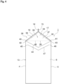
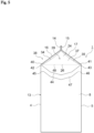
- FIG. 4 and FIG. 5 are each an explanatory view for illustrating another example of a first auxiliary folding line and a second auxiliary folding line of the paper container illustrated in FIG. 1 .
- a gable roof-type paper container 1 in this example is formed of a carton blank 2 that is a paperboard material illustrated in FIG. 2 having a thermoplastic resin laminated on each of a front surface and a back surface thereof.
- the carton blank includes four body panels 6, 7, 8, and 9 contiguous with each other through body vertical folding lines 3, 4, and 5.
- a vertical direction sealing panel 11 contiguous with the body panel 9 through a body vertical folding line 10 is joined to an edge portion 12 of the body panel 6 so that the four body panels 6, 7, 8, and 9 form a quadrangular tubular body 13 of the paper container.
- a pair of gable roof forming panels 16 and 17 are contiguous with an upper end of the body panel 7 and an upper end of the body panel 9 through top portion horizontal folding lines 18 and 19.
- the pair of gable roof forming panels 16 and 17 include outer-side top sealing panels 14 and 15 at upper portions thereof, respectively, and are opposed to each other.
- a pair of gable wall forming panels 23 and 24 are contiguous with an upper end of the body panel 6 and an upper end of the body panel 8 through top portion horizontal folding lines 25 and 26.
- the pair of gable wall forming panels 23 and 24 include inner-side top sealing panels 20 and 21 at upper portions thereof, respectively, and are opposed to each other.
- any one of the pair of gable wall forming panels 23 and 24 is formed into a pouring spout 22 and unsealed.
- the gable wall forming panel 24 serves as an unsealed-side gable wall forming panel.
- Guide folding lines 27 and 28 are formed on portions of the gable roof forming panels 16 and 17 on the unsealed-side gable wall forming panel 24 side, respectively. Along the guide folding lines 27 and 28, folding of the gable roof forming panels 16 and 17 is guided at the time of unsealing. Further, a pouring spout 31 for a straw is formed in the gable roof forming panel 16.
- the pouring spout 31 for a straw includes a first half-cut portion 29 formed on a back surface side of the gable roof forming panel 16 so as to serve as a straw slot, and a second half-cut portion 30 formed on a front surface side of the gable roof forming panel 16 so as to surround the first half-cut portion 29.
- Tuck-in folding lines 32, 33, 34, and 35 are formed on the gable wall forming panels 23 and 24, and the gable wall forming panels 23 and 24 are folded in along the tuck-in folding lines 32, 33, 34, and 35.
- the gable wall forming panel 23 includes a substantially triangular surface portion 36 surrounded by the tuck-in folding lines 32 and 33 and the top portion horizontal folding line 25
- the gable wall forming panel 24 includes a substantially triangular surface portion 37 surrounded by the tuck-in folding lines 34 and 35 and the top portion horizontal folding line 26.
- the pair of gable wall forming panels 23 and 24 are folded between the pair of gable roof forming panels 16 and 17, and the outer-side top sealing panels 14 and 15 and the inner-side top sealing panels 20 and 21 are heated, sealed, and tightly closed at predetermined positions, thereby forming a gable roof-shaped top portion 38 as illustrated in FIG. 1 .
- a space 39 is defined to have an opening between the pair of gable roof forming panels 16 and 17, the unsealed-side body panel 8, and the unsealed-side gable wall forming panel 24.
- the space 39 allows fingers to be inserted thereinto in order that the fingers are put on the unsealed-side gable wall forming panel 24 at the time of unsealing of the gable roof-type paper container 1.
- the substantially triangular surface portion 37 formed on the gable wall forming panel 24 is located on a deep plane of the space 39.
- a first auxiliary folding line 44 having a downwardly curved shape is formed to have: a left end portion 42 arranged at or near an intersection 40 of an end portion of the body vertical folding line 4 on the left of the body panel 8 and a left end portion of the top portion horizontal folding line 26; a right end portion 43 arranged at or near an intersection 41 of an end portion of the body vertical folding line 5 on the right of the body panel 8 and a right end portion of the top portion horizontal folding line 26; and a lowest point U1 located at a center of the body panel 8 in a right-and-left direction thereof.
- the end portions 42 and 43 of the first auxiliary folding line 44 are arranged near the intersection 40 of the end portion of the body vertical folding line 4 and the end portion of the top portion horizontal folding line 26 and the intersection 41 of the end portion of the body vertical folding line 5 and the end portion of the top portion horizontal folding line 26, respectively.
- the end portions 42 and 43 of the first auxiliary folding line 44 may be connected to the intersections 40 and 41, respectively.
- a second auxiliary folding line 47 having a downwardly curved shape is formed to have: a left end portion 45 arranged at or near the intersection 40 of the end portion of the body vertical folding line 4 on the left of the body panel 8 and the left end portion of the top portion horizontal folding line 26; a right end portion 46 arranged at or near the intersection 41 of the end portion of the body vertical folding line 5 on the right of the body panel 8 and the right end portion of the top portion horizontal folding line 26; and a lowest point U2 located at the center of the body panel 8 in the right-and-left direction.
- the end portions 45 and 46 of the second auxiliary folding line 47 are arranged near the intersection 40 of the end portion of the body vertical folding line 4 and the end portion of the top portion horizontal folding line 26 and the intersection 41 of the end portion of the body vertical folding line 5 and the end portion of the top portion horizontal folding line 26, respectively, and located away from the end portions 45 and 46 of the first auxiliary folding line 44, respectively.
- the end portions 45 and 46 of the second auxiliary folding line 47 may be connected to the intersections 40 and 41, respectively.
- a length L1 of an interval between the lowest point U1 of the first auxiliary folding line 44 and the lowest point U2 of the second auxiliary folding line 47 is 30% to 50% of a length L2 of an interval between a center of the top portion horizontal folding line 26 and the lowest point U1 of the first auxiliary folding line 44.
- first auxiliary folding line 44 having a downwardly curved shape and the second auxiliary folding line 47 having a downwardly curved shape may be an arc shape or an angled curve shape.
- each of the first auxiliary folding line 44 and the second auxiliary folding line 47 is formed into an arc shape, but may be, for example, an inverted V-shaped line having an angled curve shape as illustrated in FIG. 4 .
- each of the first auxiliary folding line 44 and the second auxiliary folding line 47 may be a polygonal line having an angled curve shape as illustrated in FIG. 5 .
- two auxiliary folding lines that is, the first auxiliary folding line 44 and the second auxiliary folding line 47 are formed on the unsealed-side body panel 8.
- the first auxiliary folding line 44 and the second auxiliary folding line 47 effectively guide folding of the body panel 8 as compared to a single auxiliary folding line.
- a force of pushing in the top-portion corner portion 49 of the body 13 is applied to fold the paper container along the first auxiliary folding line 44 and the second auxiliary folding line 47 formed on the body panel 8. Accordingly, the body panel 8 is mountain-folded along the first auxiliary folding line 44 and the second auxiliary folding line 47 with a relatively small force, and thus the top-portion corner portion 48 can be pushed in and dented with a relatively small force.
- the body panel 8 is first mountain-folded and dented along the first auxiliary folding line 44 and then mountain-folded and dented along the second auxiliary folding line 47, and thus the body panel 8 is prevented from being dented beyond the second auxiliary folding line 47, thereby being capable of preventing distortion of the body 13.
- the length L1 of the interval between the lowest point U1 of the first auxiliary folding line 44 and the lowest point U2 of the second auxiliary folding line 47 is 30% to 50% of the length L2 of the interval between the center of the top portion horizontal folding line 26 and the lowest point U2 of the first auxiliary folding line 44. Accordingly, when a force is applied to fold the body panel 8, the first auxiliary folding line 44 and the second auxiliary folding line 47 guide folding of the body panel 8 more effectively.
- the body panel 8 is reliably mountain-folded and dented along the first auxiliary folding line 44 and then reliably mountain-folded and dented along the second auxiliary folding line 47, and thus the body panel 8 is more effectively prevented from being dented beyond the second auxiliary folding line 47, thereby being capable of preventing distortion of the body 13 more effectively.
Landscapes
- Engineering & Computer Science (AREA)
- Mechanical Engineering (AREA)
- Cartons (AREA)
Abstract
Description
- The present invention relates to a paper container for storing a liquid content.
- Hitherto, a gable roof-type paper container has been widely used as a paper container for storing a liquid content such as milk or juice. The gable roof-type paper container is formed of a paperboard material having a thermoplastic resin laminated on each of a front surface and a back surface thereof. The gable roof-type paper container includes four body panels. A vertical direction sealing panel joins edge portions of the body panels so that a quadrangular tubular body is formed. A pair of gable roof forming panels including outer-side top sealing panels at upper portions thereof and being opposed to each other are contiguous with upper ends of the body panels are contiguous with upper ends of the body panels, and a pair of gable wall forming panels including inner-side top sealing panels at upper portions thereof and any one of which being formed into a pouring spout to be unsealed are contiguous with upper ends of the body panels. The pair of gable wall forming panels are folded between the pair of gable roof forming panels, and the outer-side top sealing panels and the inner-side top sealing panels are heated, sealed, and tightly closed at predetermined positions, thereby forming a top portion of the paper container.
- The gable roof-type paper container described above is unsealed as follows. Fingers are inserted into a space defined to have an opening between the pair of gable roof forming panels, the body panel, and the gable wall forming panel, and the fingers are put on the gable wall forming panel so as to expand the space laterally. In this manner, unsealed-side opposing surfaces between the outer-side top sealing panels and the inner-side top sealing panel, which are heated and sealed, are separated from each other. Then, the gable wall forming panel folded between the pair of gable roof forming panels is pulled, and the paper container is folded toward an outer side thereof along a top portion horizontal folding line at a boundary between the gable wall forming panel and the body panel that is contiguous with the gable wall forming panel through the top portion horizontal folding line, thereby forming the pouring spout. However, the space defined between the body panel and the gable wall forming panel is not wide, and hence the fingers are put on a small area of the gable wall forming panel so that it is difficult to unseal the paper container.
- As a paper container for solving the above-mentioned problem, in recent years, there has been known the following gable roof-type paper container (see, for example, Patent Literature 1). Specifically, the paper container includes an auxiliary folding line formed in a vicinity of a top portion horizontal folding line located at a boundary between a gable wall forming panel, which is to be pulled at the time of unsealing of the paper container, and a body panel contiguous with the gable wall forming panel. The auxiliary folding line stretches from one end portion to another end portion of the top portion horizontal folding line so as to extend downward toward a center of the body panel.
- With the gable roof-type paper container including the auxiliary folding line described above, when a top-portion corner portion of a body formed along the top portion horizontal folding line is pushed in toward an inner side of the container, the paper container is mountain-folded along the auxiliary folding line, and the top-portion corner portion is curved toward the inner side of the container so that an upper portion of the body panel located between the top portion horizontal folding line and an opening auxiliary line is dented toward the inner side of the container. Thus, a space into which fingers are to be inserted when the fingers are put on the gable wall forming panel at the time of unsealing is expanded, thereby being capable of easily unsealing the paper container.
- [PTL 1]
JP 2002-234524 - In recent years, a small-sized gable roof-type paper container has become popular as a paper container for storing drinkables for school lunches and other occasions, and as a portable and convenient paper container for storing drinkables for travel and other occasions. In the case of the small-sized gable roof-type paper container, the top portion horizontal folding line forming the top-portion corner portion of the body has a small length, and hence a relatively large force is required to push the top-portion corner portion in toward the inner side of the container in order to dent the upper portion of the body panel located between the top portion horizontal folding line and the opening auxiliary line. When the pushing-in force is small at the time of denting, the body panel is not easily dented, and when the pushing-in force is excessively large, the body panel is dented beyond the auxiliary folding line of the body panel. As a result, there is a problem in that the body may be distorted.
- It is an object of the present invention to provide a paper container, which allows a body to be pushed in and dented with a relatively small force when a top-portion corner portion of the body is pushed in at the time of unsealing, and can prevent distortion of the body even if the body is pushed in with an excessively large force.
- In order to achieve the above-mentioned object, according to the invention described in
claim 1, there is provided a paper container, which is a gable roof type and is formed of a paperboard material having a thermoplastic resin laminated on each of a front surface and a back surface of the paperboard material, the paper container comprising: four body panels; a vertical direction sealing panel, which joins edge portions of the four body panels so that the four body panels form a quadrangular body; a pair of gable roof forming panels, which are contiguous with upper ends of the body panels, and include outer-side top sealing panels at upper portions of the pair of gable roof forming panels, respectively, and are opposed to each other; a pair of gable wall forming panels, which are contiguous with upper ends of the body panels through top portion horizontal folding lines, and include inner-side top sealing panels at upper portions of the pair of gable wall forming panels, respectively, and are opposed to each other, any one of the pair of gable wall forming panels being formed into a pouring spout to be unsealed; and a top portion formed by folding the pair of gable wall forming panels between the pair of gable roof forming panels, and by heating, sealing, and tightly closing the outer-side top sealing panels and the inner-side top sealing panels at predetermined positions. On an unsealed-side body panel among the four body panels, which is contiguous with the unsealed-side gable wall forming panel through a top portion horizontal folding line, a first auxiliary folding line having a downwardly curved shape is formed to have: a left end portion arranged at or near an intersection of an end portion of a body vertical folding line on the left of the unsealed-side body panel and a left end portion of the top portion horizontal folding line; a right end portion arranged at or near an intersection of an end portion of a body vertical folding line on the right of the unsealed-side body panel and a right end portion of the top portion horizontal folding line; and a lowest point located at a center of the body panel in a right-and-left direction of the body panel, and below the first auxiliary folding line and at a predetermined distance from the first auxiliary folding line, a second auxiliary folding line having a downwardly curved shape is formed to have: a left end portion arranged at or near the intersection of the end portion of the body vertical folding line on the left of the body panel and the left end portion of the top portion horizontal folding line; a right end portion arranged at or near the intersection of the end portion of the body vertical folding line on the right of the body panel and the right end portion of the top portion horizontal folding line; and a lowest point located at the center of the body panel in the right-and-left direction. - According to the invention described in
claim 1, at the time of unsealing, when the top-portion corner portion of the body formed at the upper end portion of the unsealed-side body panel is pushed in toward the inner side of the paper container, a force of pushing the top-portion corner portion of the body in toward the inner side of the paper container is applied to the first auxiliary folding line and the second auxiliary folding line formed on the body panel. Accordingly, the body panel is mountain-folded along the first auxiliary folding line and the second auxiliary folding line with a relatively small force, and thus the top-portion corner portion can be pushed in and dented with a relatively small force. - When the top-portion corner portion is pushed in with an excessively large force, the body panel is first mountain-folded and dented along the first auxiliary folding line and then mountain-folded and dented along the second auxiliary folding line, and thus the body panel is prevented from being dented beyond the second auxiliary folding line, thereby being capable of preventing distortion of the body.
- According to the invention described in
claim 2, inclaim 1, a length of an interval between the lowest point of the first auxiliary folding line and the lowest point of the second auxiliary folding line is 30% to 50% of a length of an interval between a center of the top portion horizontal folding line and the lowest point of the first auxiliary folding line. - According to the invention described in
claim 2, the length of the interval between the lowest point of the first auxiliary folding line and the lowest point of the second auxiliary folding line is 30% to 50% of the length of the interval between the center of the top portion horizontal folding line and the lowest point of the first auxiliary folding line. Accordingly, the body panel is mountain-folded along the first auxiliary folding line and the second auxiliary folding line with a smaller force, and thus the top-portion corner portion can be pushed in and dented with a smaller force. - When the top-portion corner portion is pushed in with an excessively large force, the body panel is first mountain-folded and dented along the first auxiliary folding line and then mountain-folded and dented along the second auxiliary folding line, and thus the body panel is prevented from being dented beyond the second auxiliary folding line, thereby being capable of preventing distortion of the body.
- As described above, according to the paper container of the present invention, the body can be pushed in and dented with a relatively small force when the top-portion corner portion of the body is pushed in at the time of unsealing, and can prevent distortion of the body even if the body is pushed in with an excessively large force.
-
-
FIG. 1 is a side view for illustrating an unsealed side of an example of a paper container according to an embodiment of the present invention. -
FIG. 2 is a plan view for illustrating a carton blank for the paper container illustrated inFIG. 1 . -
FIG. 3 is an explanatory enlarged view for illustrating a part ofFIG. 2 . -
FIG. 4 is an explanatory view for illustrating another example of a first auxiliary folding line and a second auxiliary folding line of the paper container illustrated inFIG. 1 . -
FIG. 5 is an explanatory view for illustrating another example of the first auxiliary folding line and the second auxiliary folding line of the paper container illustrated inFIG. 1 . - Now, a paper container according to an embodiment of the present invention is described in detail with reference to the drawings.
-
FIG. 1 to FIG. 5 are illustrations of an example of a paper container according to an embodiment of the present invention.FIG. 1 is a side view for illustrating an unsealed side of this example of the paper container.FIG. 2 is a plan view for illustrating a carton blank for the paper container illustrated inFIG. 1 .FIG. 3 is an explanatory enlarged view for illustrating a part ofFIG. 2 .FIG. 4 andFIG. 5 are each an explanatory view for illustrating another example of a first auxiliary folding line and a second auxiliary folding line of the paper container illustrated inFIG. 1 . - A gable roof-
type paper container 1 in this example is formed of a carton blank 2 that is a paperboard material illustrated inFIG. 2 having a thermoplastic resin laminated on each of a front surface and a back surface thereof. The carton blank includes fourbody panels vertical folding lines type paper container 1, a verticaldirection sealing panel 11 contiguous with thebody panel 9 through a bodyvertical folding line 10 is joined to anedge portion 12 of thebody panel 6 so that the fourbody panels tubular body 13 of the paper container. - A pair of gable
roof forming panels body panel 7 and an upper end of thebody panel 9 through top portionhorizontal folding lines roof forming panels top sealing panels wall forming panels body panel 6 and an upper end of thebody panel 8 through top portionhorizontal folding lines wall forming panels top sealing panels wall forming panels pouring spout 22 and unsealed. In this example, the gablewall forming panel 24 serves as an unsealed-side gable wall forming panel. -
Guide folding lines roof forming panels wall forming panel 24 side, respectively. Along theguide folding lines roof forming panels pouring spout 31 for a straw is formed in the gableroof forming panel 16. Thepouring spout 31 for a straw includes a first half-cut portion 29 formed on a back surface side of the gableroof forming panel 16 so as to serve as a straw slot, and a second half-cut portion 30 formed on a front surface side of the gableroof forming panel 16 so as to surround the first half-cut portion 29. - Tuck-in
folding lines wall forming panels wall forming panels folding lines wall forming panel 23 includes a substantiallytriangular surface portion 36 surrounded by the tuck-infolding lines horizontal folding line 25, and the gablewall forming panel 24 includes a substantiallytriangular surface portion 37 surrounded by the tuck-infolding lines horizontal folding line 26. - At the time of forming the
paper container 1, the pair of gablewall forming panels roof forming panels top sealing panels top sealing panels top portion 38 as illustrated inFIG. 1 . In the gable roof-shapedtop portion 38 thus formed, aspace 39 is defined to have an opening between the pair of gableroof forming panels side body panel 8, and the unsealed-side gablewall forming panel 24. Thespace 39 allows fingers to be inserted thereinto in order that the fingers are put on the unsealed-side gablewall forming panel 24 at the time of unsealing of the gable roof-type paper container 1. The substantiallytriangular surface portion 37 formed on the gablewall forming panel 24 is located on a deep plane of thespace 39. - Further, on the unsealed-
side body panel 8, which is contiguous with the unsealed-side gablewall forming panel 24 through the top portionhorizontal folding line 26, a firstauxiliary folding line 44 having a downwardly curved shape is formed to have: aleft end portion 42 arranged at or near anintersection 40 of an end portion of the bodyvertical folding line 4 on the left of thebody panel 8 and a left end portion of the top portionhorizontal folding line 26; aright end portion 43 arranged at or near anintersection 41 of an end portion of the bodyvertical folding line 5 on the right of thebody panel 8 and a right end portion of the top portionhorizontal folding line 26; and a lowest point U1 located at a center of thebody panel 8 in a right-and-left direction thereof. - In this example, the
end portions auxiliary folding line 44 are arranged near theintersection 40 of the end portion of the bodyvertical folding line 4 and the end portion of the top portionhorizontal folding line 26 and theintersection 41 of the end portion of the bodyvertical folding line 5 and the end portion of the top portionhorizontal folding line 26, respectively. However, theend portions auxiliary folding line 44 may be connected to theintersections - In addition, on the
body panel 8, below the firstauxiliary folding line 44 and at a predetermined distance from the firstauxiliary folding line 44, a secondauxiliary folding line 47 having a downwardly curved shape is formed to have: aleft end portion 45 arranged at or near theintersection 40 of the end portion of the bodyvertical folding line 4 on the left of thebody panel 8 and the left end portion of the top portionhorizontal folding line 26; aright end portion 46 arranged at or near theintersection 41 of the end portion of the bodyvertical folding line 5 on the right of thebody panel 8 and the right end portion of the top portionhorizontal folding line 26; and a lowest point U2 located at the center of thebody panel 8 in the right-and-left direction. - In this example, the
end portions auxiliary folding line 47 are arranged near theintersection 40 of the end portion of the bodyvertical folding line 4 and the end portion of the top portionhorizontal folding line 26 and theintersection 41 of the end portion of the bodyvertical folding line 5 and the end portion of the top portionhorizontal folding line 26, respectively, and located away from theend portions auxiliary folding line 44, respectively. However, theend portions auxiliary folding line 47 may be connected to theintersections - Further, a length L1 of an interval between the lowest point U1 of the first
auxiliary folding line 44 and the lowest point U2 of the secondauxiliary folding line 47 is 30% to 50% of a length L2 of an interval between a center of the top portionhorizontal folding line 26 and the lowest point U1 of the firstauxiliary folding line 44. - The above-mentioned downwardly curved shapes of the first
auxiliary folding line 44 having a downwardly curved shape and the secondauxiliary folding line 47 having a downwardly curved shape may be an arc shape or an angled curve shape. In this example, each of the firstauxiliary folding line 44 and the secondauxiliary folding line 47 is formed into an arc shape, but may be, for example, an inverted V-shaped line having an angled curve shape as illustrated inFIG. 4 . Alternatively, each of the firstauxiliary folding line 44 and the secondauxiliary folding line 47 may be a polygonal line having an angled curve shape as illustrated inFIG. 5 . - According to the paper container configured as described above, two auxiliary folding lines, that is, the first
auxiliary folding line 44 and the secondauxiliary folding line 47 are formed on the unsealed-side body panel 8. Thus, when a force is applied to fold thebody panel 8, the firstauxiliary folding line 44 and the secondauxiliary folding line 47 effectively guide folding of thebody panel 8 as compared to a single auxiliary folding line. - Therefore, at the time of unsealing, when a top-
portion corner portion 48 of thebody 13 formed at the upper end portion of thebody panel 8 is pushed in toward an inner side of thepaper container 1, a force of pushing in the top-portion corner portion 49 of thebody 13 is applied to fold the paper container along the firstauxiliary folding line 44 and the secondauxiliary folding line 47 formed on thebody panel 8. Accordingly, thebody panel 8 is mountain-folded along the firstauxiliary folding line 44 and the secondauxiliary folding line 47 with a relatively small force, and thus the top-portion corner portion 48 can be pushed in and dented with a relatively small force. - If the top-
portion corner portion 48 is pushed in with an excessively large force, thebody panel 8 is first mountain-folded and dented along the firstauxiliary folding line 44 and then mountain-folded and dented along the secondauxiliary folding line 47, and thus thebody panel 8 is prevented from being dented beyond the secondauxiliary folding line 47, thereby being capable of preventing distortion of thebody 13. - Further, in this example, the length L1 of the interval between the lowest point U1 of the first
auxiliary folding line 44 and the lowest point U2 of the secondauxiliary folding line 47 is 30% to 50% of the length L2 of the interval between the center of the top portionhorizontal folding line 26 and the lowest point U2 of the firstauxiliary folding line 44. Accordingly, when a force is applied to fold thebody panel 8, the firstauxiliary folding line 44 and the secondauxiliary folding line 47 guide folding of thebody panel 8 more effectively. - Further, when the top-
portion corner portion 48 is pushed in with an excessively large force, thebody panel 8 is reliably mountain-folded and dented along the firstauxiliary folding line 44 and then reliably mountain-folded and dented along the secondauxiliary folding line 47, and thus thebody panel 8 is more effectively prevented from being dented beyond the secondauxiliary folding line 47, thereby being capable of preventing distortion of thebody 13 more effectively. -
- 1 paper container
- 2 carton blank
- 3, 4, 5 body vertical folding line
- 6, 7, 8, 9 body panel
- 10 body vertical folding line
- 11 vertical direction sealing panel
- 12 edge portion
- 13 body
- 14, 15 outer-side top sealing panel
- 16, 17 gable roof forming panel
- 18, 19 top portion horizontal folding line
- 20, 21 inner-side top sealing panel
- 22 pouring spout
- 23, 24 gable wall forming panel
- 25, 26 top portion horizontal folding line
- 27, 28 guide folding line
- 29 first half-cut portion
- 30 second half-cut portion
- 31 pouring spout for straw
- 32, 33, 34, 35 tuck-in folding line
- 36, 37 substantially triangular surface portion
- 38 top portion
- 39 space
- 40, 41 intersection
- 42, 43 end portion of first auxiliary folding line
- 44 first auxiliary folding line
- 45, 46 end portion of second auxiliary folding line
- 47 second auxiliary folding line
- 48 top-portion corner portion
- U1 lowest point of first auxiliary folding line
- U2 lowest point of second auxiliary folding line
- L1 length of interval between lowest point of first auxiliary folding line and lowest point of second auxiliary folding line
- L2 length of interval between center of top portion horizontal folding line and lowest point of first auxiliary folding line
Claims (2)
- A paper container, which is a gable roof type and is formed of a paperboard material having a thermoplastic resin laminated on each of a front surface and a back surface of the paperboard material, the paper container comprising:four body panels;a vertical direction sealing panel, which joins edge portions of the four body panels so that the four body panels form a quadrangular body;a pair of gable roof forming panels, which are contiguous with upper ends of the body panels, and include outer-side top sealing panels at upper portions of the pair of gable roof forming panels, respectively, and are opposed to each other;a pair of gable wall forming panels, which are contiguous with upper ends of the body panels through top portion horizontal folding lines, and include inner-side top sealing panels at upper portions of the pair of gable wall forming panels, respectively, and are opposed to each other, any one of the pair of gable wall forming panels being formed into a pouring spout to be unsealed; anda top portion formed by folding the pair of gable wall forming panels between the pair of gable roof forming panels, and by heating, sealing, and tightly closing the outer-side top sealing panels and the inner-side top sealing panels at predetermined positions,wherein on an unsealed-side body panel among the four body panels, which is contiguous with the unsealed-side gable wall forming panel through a top portion horizontal folding line, a first auxiliary folding line having a downwardly curved shape is formed to have: a left end portion arranged at or near an intersection of an end portion of a body vertical folding line on the left of the unsealed-side body panel and a left end portion of the top portion horizontal folding line; a right end portion arranged at or near an intersection of an end portion of a body vertical folding line on the right of the unsealed-side body panel and a right end portion of the top portion horizontal folding line; and a lowest point located at a center of the body panel in a right-and-left direction of the body panel, and below the first auxiliary folding line and at a predetermined distance from the first auxiliary folding line, a second auxiliary folding line having a downwardly curved shape is formed to have: a left end portion arranged at or near the intersection of the end portion of the body vertical folding line on the left of the body panel and the left end portion of the top portion horizontal folding line; a right end portion arranged at or near the intersection of the end portion of the body vertical folding line on the right of the body panel and the right end portion of the top portion horizontal folding line; and a lowest point located at the center of the body panel in the right-and-left direction.
- The paper container according to claim 1, wherein a length of an interval between the lowest point of the first auxiliary folding line and the lowest point of the second auxiliary folding line is 30% to 50% of a length of an interval between a center of the top portion horizontal folding line and the lowest point of the first auxiliary folding line.
Applications Claiming Priority (2)
| Application Number | Priority Date | Filing Date | Title |
|---|---|---|---|
| JP2022057591 | 2022-03-30 | ||
| PCT/JP2023/013398 WO2023190992A1 (en) | 2022-03-30 | 2023-03-30 | Paper container |
Publications (2)
| Publication Number | Publication Date |
|---|---|
| EP4501803A1 true EP4501803A1 (en) | 2025-02-05 |
| EP4501803A4 EP4501803A4 (en) | 2026-04-01 |
Family
ID=88202214
Family Applications (1)
| Application Number | Title | Priority Date | Filing Date |
|---|---|---|---|
| EP23781000.7A Pending EP4501803A4 (en) | 2022-03-30 | 2023-03-30 | PAPER CONTAINER |
Country Status (9)
| Country | Link |
|---|---|
| US (1) | US20250214741A1 (en) |
| EP (1) | EP4501803A4 (en) |
| JP (1) | JPWO2023190992A1 (en) |
| KR (1) | KR20240169063A (en) |
| AU (1) | AU2023243244A1 (en) |
| CA (1) | CA3246978A1 (en) |
| MA (1) | MA68019A1 (en) |
| MX (1) | MX2024011809A (en) |
| WO (1) | WO2023190992A1 (en) |
Family Cites Families (7)
| Publication number | Priority date | Publication date | Assignee | Title |
|---|---|---|---|---|
| US3537634A (en) * | 1969-05-19 | 1970-11-03 | Phillips Petroleum Co | Pushbutton opener for gable top containers |
| JPH066713B2 (en) * | 1985-05-17 | 1994-01-26 | 日本油脂株式会社 | Hydraulic fluid |
| US5474232A (en) * | 1994-05-06 | 1995-12-12 | Ljungstroem; Tommy B. G. | Gable top carton and carton blank with curved side creases |
| JP2002234524A (en) | 2001-02-07 | 2002-08-20 | Toppan Printing Co Ltd | Gable-top paper container |
| JP5234932B2 (en) * | 2008-06-30 | 2013-07-10 | 日本製紙株式会社 | Paper container |
| EP2298656B1 (en) * | 2008-06-30 | 2013-11-20 | Nippon Paper Industries Co., Ltd | Paper container |
| JP7584226B2 (en) * | 2020-03-23 | 2024-11-15 | 日本製紙株式会社 | Paper containers |
-
2023
- 2023-03-30 AU AU2023243244A patent/AU2023243244A1/en active Pending
- 2023-03-30 EP EP23781000.7A patent/EP4501803A4/en active Pending
- 2023-03-30 CA CA3246978A patent/CA3246978A1/en active Pending
- 2023-03-30 US US18/851,370 patent/US20250214741A1/en active Pending
- 2023-03-30 KR KR1020247035908A patent/KR20240169063A/en active Pending
- 2023-03-30 WO PCT/JP2023/013398 patent/WO2023190992A1/en not_active Ceased
- 2023-03-30 JP JP2024512861A patent/JPWO2023190992A1/ja active Pending
-
2024
- 2024-09-26 MX MX2024011809A patent/MX2024011809A/en unknown
- 2024-10-08 MA MA68019A patent/MA68019A1/en unknown
Also Published As
| Publication number | Publication date |
|---|---|
| MX2024011809A (en) | 2024-11-08 |
| AU2023243244A1 (en) | 2024-11-14 |
| WO2023190992A1 (en) | 2023-10-05 |
| CA3246978A1 (en) | 2025-07-08 |
| EP4501803A4 (en) | 2026-04-01 |
| JPWO2023190992A1 (en) | 2023-10-05 |
| KR20240169063A (en) | 2024-12-02 |
| MA68019A1 (en) | 2026-03-31 |
| US20250214741A1 (en) | 2025-07-03 |
Similar Documents
| Publication | Publication Date | Title |
|---|---|---|
| JP7106783B1 (en) | paper container | |
| JP7352046B2 (en) | paper container | |
| EP3689769A1 (en) | Liquid paper container | |
| KR900701608A (en) | A box with a spout | |
| US20250214741A1 (en) | Paper container | |
| JP2019123540A (en) | Gable-top container | |
| US12503269B2 (en) | Paper container | |
| JP5234932B2 (en) | Paper container | |
| JP2010006459A (en) | Paper container | |
| JP7106592B2 (en) | paper container | |
| EP4613666A1 (en) | Paper container | |
| EP4653334A1 (en) | Paper container | |
| JP7077471B2 (en) | Paper container | |
| JP7864004B2 (en) | paper container | |
| JPS6126171Y2 (en) | ||
| JP2024018000A (en) | paper container | |
| JP2024018001A (en) | paper container | |
| JP2023161249A (en) | gable roof type paper container | |
| JP2023162510A (en) | paper container | |
| US3679124A (en) | Container with opening feature | |
| WO2022210813A1 (en) | Paper container | |
| JP6801977B2 (en) | Gable top type container | |
| US4441608A (en) | Display carton | |
| JP2017190164A (en) | Gable top type container | |
| JP2017178389A (en) | Gable-top container and panel for gable-top container |
Legal Events
| Date | Code | Title | Description |
|---|---|---|---|
| STAA | Information on the status of an ep patent application or granted ep patent |
Free format text: STATUS: THE INTERNATIONAL PUBLICATION HAS BEEN MADE |
|
| PUAI | Public reference made under article 153(3) epc to a published international application that has entered the european phase |
Free format text: ORIGINAL CODE: 0009012 |
|
| STAA | Information on the status of an ep patent application or granted ep patent |
Free format text: STATUS: REQUEST FOR EXAMINATION WAS MADE |
|
| 17P | Request for examination filed |
Effective date: 20241011 |
|
| AK | Designated contracting states |
Kind code of ref document: A1 Designated state(s): AL AT BE BG CH CY CZ DE DK EE ES FI FR GB GR HR HU IE IS IT LI LT LU LV MC ME MK MT NL NO PL PT RO RS SE SI SK SM TR |
|
| DAV | Request for validation of the european patent (deleted) | ||
| DAX | Request for extension of the european patent (deleted) | ||
| A4 | Supplementary search report drawn up and despatched |
Effective date: 20260303 |
|
| RIC1 | Information provided on ipc code assigned before grant |
Ipc: B65D 5/06 20060101AFI20260225BHEP Ipc: B65D 5/74 20060101ALI20260225BHEP Ipc: B65D 5/42 20060101ALI20260225BHEP |