EP4501795A1 - Flight device and flight device control method - Google Patents
Flight device and flight device control method Download PDFInfo
- Publication number
- EP4501795A1 EP4501795A1 EP23779662.8A EP23779662A EP4501795A1 EP 4501795 A1 EP4501795 A1 EP 4501795A1 EP 23779662 A EP23779662 A EP 23779662A EP 4501795 A1 EP4501795 A1 EP 4501795A1
- Authority
- EP
- European Patent Office
- Prior art keywords
- engine
- rotor
- unit
- power transmission
- transmission unit
- Prior art date
- Legal status (The legal status is an assumption and is not a legal conclusion. Google has not performed a legal analysis and makes no representation as to the accuracy of the status listed.)
- Pending
Links
Images



Classifications
-
- B—PERFORMING OPERATIONS; TRANSPORTING
- B64—AIRCRAFT; AVIATION; COSMONAUTICS
- B64U—UNMANNED AERIAL VEHICLES [UAV]; EQUIPMENT THEREFOR
- B64U50/00—Propulsion; Power supply
- B64U50/20—Transmission of mechanical power to rotors or propellers
- B64U50/27—Transmission of mechanical power to rotors or propellers with a single motor serving two or more rotors or propellers
-
- B—PERFORMING OPERATIONS; TRANSPORTING
- B64—AIRCRAFT; AVIATION; COSMONAUTICS
- B64D—EQUIPMENT FOR FITTING IN OR TO AIRCRAFT; FLIGHT SUITS; PARACHUTES; ARRANGEMENT OR MOUNTING OF POWER PLANTS OR PROPULSION TRANSMISSIONS IN AIRCRAFT
- B64D31/00—Power plant control systems; Arrangement of power plant control systems in aircraft
- B64D31/02—Initiating means
- B64D31/06—Initiating means actuated automatically
-
- B—PERFORMING OPERATIONS; TRANSPORTING
- B64—AIRCRAFT; AVIATION; COSMONAUTICS
- B64U—UNMANNED AERIAL VEHICLES [UAV]; EQUIPMENT THEREFOR
- B64U50/00—Propulsion; Power supply
- B64U50/10—Propulsion
- B64U50/11—Propulsion using internal combustion piston engines
-
- B—PERFORMING OPERATIONS; TRANSPORTING
- B64—AIRCRAFT; AVIATION; COSMONAUTICS
- B64U—UNMANNED AERIAL VEHICLES [UAV]; EQUIPMENT THEREFOR
- B64U50/00—Propulsion; Power supply
- B64U50/20—Transmission of mechanical power to rotors or propellers
- B64U50/23—Transmission of mechanical power to rotors or propellers with each propulsion means having an individual motor
-
- B—PERFORMING OPERATIONS; TRANSPORTING
- B64—AIRCRAFT; AVIATION; COSMONAUTICS
- B64U—UNMANNED AERIAL VEHICLES [UAV]; EQUIPMENT THEREFOR
- B64U50/00—Propulsion; Power supply
- B64U50/30—Supply or distribution of electrical power
- B64U50/33—Supply or distribution of electrical power generated by combustion engines
-
- B—PERFORMING OPERATIONS; TRANSPORTING
- B64—AIRCRAFT; AVIATION; COSMONAUTICS
- B64U—UNMANNED AERIAL VEHICLES [UAV]; EQUIPMENT THEREFOR
- B64U10/00—Type of UAV
- B64U10/10—Rotorcrafts
- B64U10/13—Flying platforms
- B64U10/16—Flying platforms with five or more distinct rotor axes, e.g. octocopters
-
- Y—GENERAL TAGGING OF NEW TECHNOLOGICAL DEVELOPMENTS; GENERAL TAGGING OF CROSS-SECTIONAL TECHNOLOGIES SPANNING OVER SEVERAL SECTIONS OF THE IPC; TECHNICAL SUBJECTS COVERED BY FORMER USPC CROSS-REFERENCE ART COLLECTIONS [XRACs] AND DIGESTS
- Y02—TECHNOLOGIES OR APPLICATIONS FOR MITIGATION OR ADAPTATION AGAINST CLIMATE CHANGE
- Y02T—CLIMATE CHANGE MITIGATION TECHNOLOGIES RELATED TO TRANSPORTATION
- Y02T50/00—Aeronautics or air transport
- Y02T50/60—Efficient propulsion technologies, e.g. for aircraft
Definitions
- the present invention relates to a flight device and specifically relates to a flight device in which the main rotor is driven by an engine and a method of controlling the flight device.
- Flight devices capable of unmanned flight in the air have been known. Such a flight device is able to fly in the air using the thrust of a rotor rotating about a vertical axis.
- Flight devices include the field of transportation, the field of surveying, and the field of photography, for example.
- surveying equipment and photography equipment are attached to the flight devices.
- the flight devices can fly in areas that human cannot access and perform transportation, photographing, and surveying of such areas.
- Inventions relating to such flight devices are described in Patent Literature 1 and Patent Literature 2, for example.
- a typical flight device the aforementioned rotor rotates using electric power supplied from a storage battery mounted on the flight device.
- energy supply by the electric power of the storage battery may not always be sufficient.
- flight devices equipped with engines also have emerged.
- a generator is rotated using driving force of the engine, and the rotor is rotationally driven using electric power generated by the generator.
- the engine and the generator are connected in series on a path of energy supplied from the power source to the rotor.
- Such a flight device is therefore called a series-type drone. Use of such flight devices enables photography and surveying of wide areas.
- Patent Literature 3 A flight device equipped with an engine is described in Patent Literature 3, for example. Furthermore, parallel-type hybrid drones are also gradually emerging, in which the main rotor is mechanically rotated using the driving force of the engine and a sub-rotor is rotated using a motor.
- a power connection/disconnection unit such as a clutch
- the power connection/disconnection unit is, for example, a centrifugal clutch, which does not connect the engine to the rotor while the engine speed is low and connects the engine to the rotor when the engine speed is increased.
- the present invention was made in the light of the aforementioned circumstances, and an object thereof is to provide a flight device and a flight device control method which ensure safety even if a defect occurs in the power connection/disconnection unit.
- a flight device of the present invention includes: an airframe; a main rotor; an engine; an engine-side power transmission unit; a rotor-side power transmission unit; a power connection/disconnection unit; and an arithmetic control unit, the main rotor rotates to generate driving force necessary for the airframe to float, the engine generates power necessary for the main rotor to rotate, the engine-side power transmission unit rotates using the power of the engine, the rotor-side power transmission unit is drivingly connected to the main rotor, the power connection/disconnection unit is provided between the engine-side power transmission unit and the rotor-side power transmission unit and transmits the power from the engine-side power transmission unit to the rotor-side power transmission unit according to conditions, and the arithmetic control unit changes a flight status when the degree to which the power connection/disconnection unit transmits the power differs from a predetermined value by a certain amount or more.
- a flight device of the present invention includes: an airframe; a main rotor; an engine; an engine-side power transmission unit; a rotor-side power transmission unit; a power connection/disconnection unit; and an arithmetic control unit,
- the main rotor rotates to generate driving force necessary for the airframe to float and includes a first main rotor and a second main rotor
- the engine generates power necessary for the first main rotor and the second main rotor to rotate
- the engine-side power transmission unit rotates using the power of the engine and includes a first engine-side power transmission unit and a second engine-side power transmission unit
- the rotor-side power transmission unit includes a first rotor-side power transmission unit drivingly connected to the first main rotor and a second rotor-side power transmission unit drivingly connected to the second main rotor
- the power connection/disconnection unit transmits the power according to conditions and includes a first power connection/disconnection unit and a second power connection/d
- the arithmetic control unit stops the engine.
- the arithmetic control unit in a case of changing the flight status in a flight state, the arithmetic control unit lands the flight device by using the driving force of the engine.
- the flight device of the present invention further includes: a sub-rotor; and a motor that rotates the sub-rotor, in a case of changing the flight status in a flight state, the arithmetic control unit stops the engine and lands the flight device by rotating the sub-rotor using the motor.
- the arithmetic control unit lands the flight device while running the engine when the difference between the degree to which the first power connection/disconnection unit transmits the power and the degree to which the second power connection/disconnection unit transmits the power is greater than a second setting value.
- the arithmetic control unit lands the flight device with the engine stopped when the difference between the degree to which the first power connection/disconnection unit transmits the power and the degree to which the second power connection/disconnection unit transmits the power is greater than a third setting value.
- the arithmetic control unit changes the flight status when the absolute value of the difference between the rotational speed of the first rotor-side power transmission unit and the rotational speed of the second rotor-side power transmission unit is more than or equal to a certain value.
- the present invention is a method of controlling a flight device, the flight device includes: an airframe; a main rotor; an engine; an engine-side power transmission unit; a rotor-side power transmission unit; and a power connection/disconnection unit, the main rotor rotating to generate driving force necessary for the airframe to float, the engine generating power necessary for the main rotor to rotate, the engine-side power transmission unit rotating using the power of the engine, the rotor-side power transmission unit being drivingly connected to the main rotor; and the power connection/disconnection unit being provided between the engine-side power transmission unit and the rotor-side power transmission unit and transmitting the power from the engine-side power transmission unit to the rotor-side power transmission unit according to conditions, the method includes: changing a flight status when the degree to which the power connection/disconnection unit transmits the power differs from a predetermined value by a certain amount or more.
- a flight device of the present invention includes an airframe, a main rotor, an engine, an engine-side power transmission unit, a rotor-side power transmission unit, a power connection/disconnection unit, and an arithmetic control unit, in which the main rotor rotates to generate driving force necessary for the airframe to float, the engine generates power necessary for the main rotor to rotate, the engine-side power transmission unit rotates using the power of the engine, the rotor-side power transmission unit is drivingly connected to the main rotor, the power connection/disconnection unit is provided between the engine-side power transmission unit and the rotor-side power transmission unit and transmits the power from the engine-side power transmission unit to the rotor-side power transmission unit according to conditions, and the arithmetic control unit changes a flight status when the degree to which the power connection/disconnection unit transmits the power differs from a predetermined value by a certain amount or more. According to the flight device of the present invention, the arithmetic control unit
- a flight device of the present invention includes an airframe, a main rotor, an engine, an engine-side power transmission unit, a rotor-side power transmission unit, a power connection/disconnection unit, and an arithmetic control unit, in which the main rotor rotates to generate driving force necessary for the airframe to float and includes a first main rotor and a second main rotor, the engine generates power necessary for the first main rotor and the second main rotor to rotate, the engine-side power transmission unit rotates using the power of the engine and includes a first engine-side power transmission unit and a second engine-side power transmission unit, the rotor-side power transmission unit includes a first rotor-side power transmission unit drivingly connected to the first main rotor and a second rotor-side power transmission unit drivingly connected to the second main rotor, the power connection/disconnection unit transmits the power according to conditions and includes a first power connection/disconnection unit and a second power connection/disconnection unit
- the flight status is changed when the degree to which the first power connection/disconnection unit transmits power and the degree to which the second power connection/disconnection unit transmits power differ by a certain amount or more, thus allowing the flight device to fly more safely.
- the flight device of the present invention further includes: a first rotational speed measurement unit measuring rotational speed of the first rotor-side power transmission unit; and a second rotational speed measurement unit measuring rotational speed of the second rotor-side power transmission unit, in which the arithmetic control unit changes the flight status when the rotational speed of the first rotor-side power transmission unit measured by the first rotational speed measurement unit and the rotational speed of the second rotor-side power transmission unit measured by the second rotational speed measurement unit differ by a certain amount or more.
- the flight status is changed when the rotational speed of the first rotor-side power transmission unit and the rotational speed of the second rotor-side power transmission unit differ by a certain amount or more, thus allowing the flight device to fly more safely.
- the arithmetic control unit stops the engine.
- the engine in a process of changing the flight status in the landing state, the engine is stopped, thus preventing the flight device from flying in the condition where power transmission by the power connection/disconnection unit is not good.
- the arithmetic control unit in a case of changing the flight status in a flight state, the arithmetic control unit lands the flight device by using the driving force of the engine. According to the flight device of the present invention, even when a defect occurs in the power connection/disconnection unit in the flight state, the flight device is able to land by using the driving force of the engine.
- the flight device of the present invention further includes: a sub-rotor; and a motor that rotates the sub-rotor, in which in a case of changing the flight status in a flight state, the arithmetic control unit stops the engine and lands the flight device by rotating the sub-rotor using the motor. According to the flight device of the present invention, even when a defect occurs in the power connection/disconnection unit in the flight state, the flight device is able to land safely due to the sub-rotor.
- the arithmetic control unit cancels the flight when the difference between the degree to which the first power connection/disconnection unit transmits the power and the degree to which the second power connection/disconnection unit transmits the power is greater than a first setting value.
- a defect in the power connection/disconnection unit is determined based on the first setting value, and the flight itself of the flight device is canceled. It is therefore possible to prevent unstable flight of the flight device.
- the arithmetic control unit lands the flight device while running the engine when the difference between the degree to which the first power connection/disconnection unit transmits the power and the degree to which the second power connection/disconnection unit transmits the power is greater than a second setting value.
- a defect in the power connection/disconnection unit is determined based on the second setting value, and the flight device is landed with the engine running. It is therefore possible to stably execute landing operation of the flight device when a defect occurs.
- the arithmetic control unit lands the flight device with the engine stopped when the difference between the degree to which the first power connection/disconnection unit transmits the power and the degree to which the second power connection/disconnection unit transmits the power is greater than a third setting value.
- a defect in the power connection/disconnection unit is determined based on the third setting value, and the flight device is landed after the engine is stopped. It is therefore possible to more stably execute landing operation of the flight device.
- the arithmetic control unit changes the flight status when the absolute value of the difference between the rotational speed of the first rotor-side power transmission unit and the rotational speed of the second rotor-side power transmission unit is more than or equal to a certain value. According to the flight device of the present invention, in a case where it is difficult to stabilize the flight state, the flight status is changed, and the flight device can thereby be operated more safely.
- the present invention is a method of controlling a flight device, the flight device including an airframe, a main rotor, an engine, an engine-side power transmission unit, a rotor-side power transmission unit, and a power connection/disconnection unit, the main rotor rotating to generate driving force necessary for the airframe to float, the engine generating power necessary for the main rotor to rotate, the engine-side power transmission unit rotating using the power of the engine, the rotor-side power transmission unit being drivingly connected to the main rotor; and the power connection/disconnection unit being provided between the engine-side power transmission unit and the rotor-side power transmission unit and transmitting the power from the engine-side power transmission unit to the rotor-side power transmission unit according to conditions, the method including: changing a flight status when the degree to which the power connection/disconnection unit transmits the power differs from a predetermined value by a certain amount or more.
- the arithmetic control unit changes the flight status when the
- a flight device 10 is also called a drone and specifically also called a parallel-type hybrid drone.
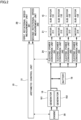
- Fig. 1 is a schematic diagram illustrating the flight device 10.
- the flight device 10 mainly includes an airframe 19, main rotors 14, an engine 30, engine-side power transmission units 25, rotor-side power transmission units 26, power connection/disconnection units 27, and an arithmetic control unit 31.
- the flight device 10 is a parallel-type hybrid drone including two driving systems in parallel, an electric driving system and a mechanical driving system.
- the electric driving system rotates motors 21 and sub-rotors 15, which will be described later.
- the mechanical driving system rotates the main rotors 14, which will be described later.
- the airframe 19 is a body supporting the units constituting the fright device 10 and is made of synthetic resin, metal, or a composite material thereof.
- the main rotors 14 rotate to generate driving force necessary for the airframe 19 to float and includes a first main rotor 141 and a second main rotor 142.
- the first main rotor 141 is arranged to the left of the airframe 19.
- the second main rotor 142 is arranged to the right of the airframe 19.
- the first main rotor 141 and the second main rotor 142 rotate in opposite directions at the same rotational speed.
- the first main rotor 141 is connected to the engine 30 so as to be driven, with a first engine-side power transmission unit 251, a first power connection/disconnection unit 271, and a first rotor-side power transmission unit 261 interposed therebetween.
- the second main rotor 142 is connected to the engine 30 so as to be driven, with a second engine-side power transmission unit 252, a second power connection/disconnection unit 272, and a second rotor-side power transmission unit 262 interposed therebetween.
- the engine 30 generates power necessary for the first main rotor 141 and the second main rotor 142 to rotate.
- the engine 30 is incorporated in the airframe 19 and rotates the first main rotor 141 and the second main rotor 142 at a predetermined rotational speed.
- the engine 30 includes a first engine unit 40 and a second engine unit 41 as will be described later with reference to Fig. 3 .
- the engine-side power transmission units 25 are, for example, a steel rod and rotate using the power of the engine 30.
- the engine-side power transmission units 25 include the first engine-side power transmission unit 251 and the second engine-side power transmission unit 252.
- the first engine-side power transmission unit 251 and the second engine-side power transmission unit 252 are connected to crankshafts of the engine 30 so as to be driven.
- the first engine-side power transmission unit 251 protrudes from the engine 30 to the left.
- the second engine-side power transmission unit 252 protrudes from the engine 30 to the right.
- the rotor-side power transmission units 26 are, for example, a steel rod.
- the rotor-side power transmission units 26 include the first rotor-side power transmission unit 261, which is drivingly connected to the first main rotor 141, and the second rotor-side transmission unit 262, which is drivingly connected to the second main rotor 142.
- the first rotor-side power transmission unit 261 and the first main rotor 141 are drivingly connected with a gear 171 interposed therebetween.
- the second rotor-side power transmission unit 262 and the second main rotor 142 are drivingly connected with a gear 172 interposed therebetween.
- the power connection/disconnection units 27 are constituent units that transmit power according to conditions and are, for example, a clutch.
- the power connection/disconnection units 27 are a centrifugal clutch by way of example.
- the power connection/disconnection units 27 include the first power connection/disconnection unit 271 and the second power connection/disconnection unit 272.
- the centrifugal clutch is also referred to as a centrifugal type clutch.
- the first power connection/disconnection unit 271 is provided between the first engine-side power transmission unit 251 and the first rotor-side power transmission unit 261.
- the first power connection/disconnection unit 271 does not transmit power.
- the first power connection/disconnection unit 271 transmits power from the first engine-side power transmission unit 251 to the first rotor-side power transmission unit 261.
- the power generated by the engine 30 is thereby transmitted to the first engine-side power transmission unit 251, the first power connection/disconnection unit 271, and the first rotor-side power transmission unit 261, so that the first main rotor 141 rotates.
- the configuration and operation of the second power connection/disconnection unit 272 are the same as those of the first power connection/disconnection unit 271. Specifically, the second power connection/disconnection unit 272 is provided between the second engine-side power transmission unit 252 and the second rotor-side power transmission unit 262. When the engine 30 is stopped and the second engine-side power transmission unit 252 does not rotate or when the rotational speed of the second engine-side power transmission unit 252 rotated by the engine 30 is lower than the certain level, the second power connection/disconnection unit 272 does not transmit power.
- the second power connection/disconnection unit 272 transmits power from the second engine-side power transmission unit 252 to the second rotor-side power transmission unit 262.
- the power generated by the engine 30 is thereby transmitted to the second engine-side power transmission unit 252, the second power connection/disconnection unit 272, and the second rotor-side power transmission unit 262, so that the second main rotor 142 rotates.
- a first main frame 121 extends to the left from the airframe 19.
- the first engine-side power transmission unit 251 and the first rotor-side power transmission unit 261, which are described above, are incorporated in the first main frame 121, which is tubular, for example.
- the first power connection/disconnection unit 271 is provided in the middle of the first main frame 121.
- a second main frame 122 extends to the right from the airframe 19.
- the second engine-side power transmission unit 252 and the second rotor-side power transmission unit 262, which are described above, are incorporated in the second main frame 122.
- the second power connection/disconnection unit 272 is provided in the middle of the second main frame 122.
- the flight device 10 includes sub-rotors 15.
- the sub-rotors 15 include sub-rotors 151 to 154.
- the sub-rotors 15 rotate to control the overall position and orientation of the flight device 10.
- the sub-rotor 151 is positioned at the front left of the airframe 19.
- the sub-rotor 151 is connected to the airframe 19 through a sub-frame 131 and is rotated by a motor 211.
- the sub-rotor 152 is positioned at the back left of the airframe 19.
- the sub-rotor 152 is connected to the airframe 19 through a sub-frame 132 and is rotated by a motor 212.
- the sub-rotor 153 is positioned at the front right of the airframe 19.
- the sub-rotor 153 is connected to the airframe 19 through a sub-frame 133 and is rotated by a motor 213.
- the sub-rotor 154 is positioned at the back right of the airframe 19.
- the sub-rotor 154 is connected to the airframe 19 through a sub-frame 134 and is rotated by a motor 214.
- the behavior of the power connection/disconnection units 27 will be described.
- the power connection/disconnection units 27, which are, for example, a centrifugal clutch, has a function of transmitting power when the rotational speed is not lower than a certain level.
- the power connection/disconnection units 27 are a complicated mechanical mechanism, and the components constituting the power connection/disconnection units 27 have a certain level of tolerance.
- the first power connection/disconnection unit 271 and the second power connection/disconnection unit 272 may therefore behave slightly differently.
- the first power connection/disconnection unit 271 transmits power to the first rotor-side power transmission unit 261 while the second power connection/disconnection unit 272 does not transmit power to the second rotor-side power transmission unit 262.
- the first main rotor 141 is rotating
- the second main rotor 142 does not rotate, so that the flight device 10 may be unable to take off stably.
- any one of the first power connection/disconnection unit 271 or the second power connection/disconnection unit 272 mechanically fails.
- the operation of the flight device 10 is controlled based on the rotational speeds of the first engine-side power transmission unit 251 and the second engine-side power transmission unit 252. This matter will be described later with reference to Fig. 4 .
- Fig. 2 is a diagram illustrating the flight device 10 and is a block diagram illustrating the connection configuration of each portion.
- the flight device 10 includes the arithmetic control unit 31, the engine 30, generators 16, a battery 18, electric power conversion units 24, the motors 21, the sub-rotors 15, and a rotational speed measurement unit 28.
- the arithmetic control unit 31 includes a CPU, a ROM, a RAM, and the like.
- the arithmetic control unit 31 controls the behavior of each unit constituting the flight device 10 based on inputs from various sensors and a controller not illustrated herein.
- the arithmetic control unit 31 serves as a flight controller that controls the rotational speed of the main rotors 14 and sub-rotors 15 based on inputs from various sensors.
- the engine 30 operates based on input signals from the arithmetic control unit 31 and generates energy necessary for the flight device 10 to fly.
- the specific configuration of the engine 30 will be described later with reference to a drawing.
- the generators 16 are units that generate electric power by using a part of the driving force of the engine 30 and include generators 161 and 162.
- the generator 161 is driven by the first engine unit 40 of the engine 30, which will be described later.
- the generator 162 is driven by the second engine unit 41 of the engine 30, which will be described later.
- the battery 18 is interposed between the generators 16 and the electric power conversion units 24.
- the battery 18 is charged by the generators 16.
- the electric power discharged from the battery 18 is supplied to the electric power conversion units 24, which will be described later.
- the electric power conversion units 24 are provided corresponding to the respective sub-rotors 15.
- Each power conversion unit 24 can be composed of a converter and an inverter to once convert alternating-current power supplied from the generator 162 into direct-current power and then convert the direct-current power into alternating-current power with a predetermined frequency.
- Each electric power conversion unit 24 also can be composed of an inverter to convert direct-current power supplied from the battery 18 into alternating-current power with a predetermined frequency.
- the electric power conversion units 24 include electric power conversion units 241, 242, 243, and 244.
- the motors 21 are provided corresponding to the respective sub-rotors 15.
- the motors 21 include motors 211, 212, 213, and 214.
- the motors 211, 212, 213, and 214 rotate at a predetermined speed using electric power supplied from the electric power conversion units 241 to 244, respectively.
- the sub-rotors 15 include the sub-rotors 151 to 154 as described above.
- the sub-rotors 151 to 154 are rotated by the motors 211 to 214, respectively.
- the rotational speed measurement unit 28 measures the rotational speed of the engine-side power transmission units 25, which is illustrated in Fig. 1 , and input an electric signal representing the measured rotational speed to the arithmetic control unit 31.
- the rotational speed measurement unit 28 includes a first rotational speed measurement unit 281 and a second rotational speed measurement unit 282.
- the first rotational speed measurement unit 281 measures the rotational speed of the first rotor-side power transmission unit 261.
- the second rotational speed measurement unit 282 measures the rotational speed of the second rotor-side power transmission unit 262.
- the arithmetic control unit 31 changes the flight status when the rotational speed of the first rotor-side power transmission unit 261 measured by the first rotational speed measurement unit 281 and the rotational speed of the second rotor-side power transmission unit 262 measured by the second rotational speed measurement unit 282 differ by a certain amount or more.
- changing the flight status is, for example stopping the flight device 10 from taking off, urgently landing the flight device 10 flying normally, and other operations.
- the flight status of the flight device 10 will be briefly described.
- the flight device 10 is operated in a landing state, a takeoff state, a hovering state, an ascending-descending state, a horizontal movement state, and an emergency flight state.
- the flight device 10 In the landing state, the flight device 10 is in contact with the ground. In this state, the engine 30 is not running, and the engine-side power transmission units 25 do not rotate. The power connection/disconnection units 27 are in a disconnected state, and the rotor-side power transmission units 26 and the main rotors 14 do not rotate.
- the flight device 10 In the takeoff state, the flight device 10 is rising away from the contact surface mainly due to the thrust generated by rotation of the main rotors 14.
- the main rotors 14 are rotated using the driving force generated by the engine 30 to keep the flight device 10 floating at a predetermined position in the air.
- the sub-rotors 15 are rotating based on an instruction from the arithmetic control unit 31.
- the arithmetic control unit 31 controls the electric power conversion units 24 to set the rotational speeds of the motors 21 and sub-rotors 15 to predetermined values so that the flight device 10 can maintain its predetermined altitude and orientation.
- the flight device 10 In the ascending-descending state, the flight device 10 is raised or lowered by controlling the rotational speed of the engine 30.
- the arithmetic control unit 31 controls the electric power conversion units 24 to set the rotational speeds of the motors 21 and sub-rotors 15 to predetermined values so that the flight device 10 can maintain its predetermined altitude and orientation.
- the arithmetic control unit 31 controls the electric power conversion units 24 to control the rotational speeds of the motors 21 and sub-rotors 15 so that the flight device 10 be tilted. In this process as well, the arithmetic control unit 31 controls the running state of the engine 30 to rotate the main rotors 14 at a predetermined speed.
- the arithmetic control unit 31 forces the flight device 10 that is flying to land.
- the emergency flight state is activated when the rotational speed measured in the first rotational speed measurement unit 281 and the rotational speed measured in the second rotational speed measurement unit 282 differ by a certain amount or more.
- Fig. 3 is a diagram illustrating the configuration and arrangement of the engine 30 of the flight device 10.
- the engine 30 includes the first engine unit 40 and the second engine unit 41.
- the first engine unit 40 and the second engine unit 41 are positioned opposite to each other.
- the first engine unit 40 is positioned in the back left while the second engine unit 41 is positioned in the front right.
- the first engine unit 40 includes: a first piston 43, which reciprocates; a first crankshaft 42, which converts reciprocating motion of the first piston 43 into rotational motion; and a first connecting rod 44, which rotatably couples the first piston 43 to the first crankshaft 42.
- the second engine unit 41 includes: a second piston 46, which reciprocates; a second crankshaft 45, which converts reciprocating motion of the second piston 46 into rotational motion; and a second connecting rod 47, which rotatably couples the second piston 46 to the second crankshaft 45.
- the first piston 43 of the first engine unit 40 and the second piston 46 of the second engine unit 41 share a combustion chamber 48.
- the first piston 43 and the second piston 46 reciprocate within a single continuing cylinder 49.
- the engine 30 includes a volume space (not illustrated herein) communicating with the combustion chamber 48.
- a spark plug is arranged in the volume space.
- an intake port and an exhaust port which are not illustrated herein, are formed in the combustion chamber 48.
- An air-mixture containing fuel, such as gasoline, is introduced into the combustion chamber 48 through the intake port, and exhaust gas after combustion is discharged from the combustion chamber 48 to the outside through the exhaust port.
- the flight device 10 By mounting the thus-configured engine 30 on the flight device 10, the flight device 10 can be reduced in size, weight, and vibrations. Due to the reduction in vibrations in particular, it is possible to prevent delicate equipment, such as arithmetic control devices and GPS sensors, from being adversely affected by orientation control or motor output control. Furthermore, it is possible to prevent parcels being transported by the flight device 10 from being damaged by vibrations.
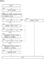
- step S10 the arithmetic control unit 31 starts the engine 30 based on an operator's instruction through the controller.
- the first engine-side power transmission unit 251 and the second engine-side power transmission unit 252 are thereby rotated using the driving force of the engine 30.
- the flight device 10 is placed on a contact surface, which is the ground, for example.
- step S11 the arithmetic control unit 31 transitions from the landing state to the takeoff state.
- the landing state refers to a state where the flight device 10 is in contact with the ground.
- the takeoff state refers to a state where the flight device 10 is rising from the landing state and lifting off from the ground.
- step S11 specifically, when the rotational speed of the first engine-side power transmission unit 251 reaches a predetermined rotational speed, the first power connection/disconnection unit 271 enters a connected state, and the first engine-side power transmission unit 251, the first rotor-side power transmission unit 261, and the first main rotor 141 rotate.
- the second power connection/disconnection unit 272 when the rotational speed of the second engine-side power transmission unit 252 reaches a predetermined rotational speed, the second power connection/disconnection unit 272 enters a connected state, and the second engine-side power transmission unit 252, the second rotor-side power transmission unit 262, and the second main rotor 142 rotate.
- step S11 is continued in this condition, the flight device 10 may lose its balance and may be unable to stably transition to the takeoff state. In this embodiment, therefore, the flight is cancelled depending on the condition of the first power connection/disconnection unit 271 or the second power connection/disconnection unit 272 as will be described later.
- step S12 the arithmetic control unit 31 checks the difference in rotational speed between the first rotor-side power transmission unit 261 and the second rotor-side power transmission unit 262. Specifically, the arithmetic control unit 31 determines whether the absolute value of the difference between ⁇ 1 and ⁇ 2 is greater than ⁇ 1 where ⁇ 1 is the rotational speed of the first rotor-side power transmission unit 261, ⁇ 2 is the rotational speed of the second rotor-side power transmission unit 262, and ⁇ 1 is a predetermined allowable speed difference.
- step S12 determines whether the determination in step S12 is YES, that is, if the absolute value of the difference between ⁇ 1 and ⁇ 2 is greater than ⁇ 1 (a first setting value).
- the arithmetic control unit 31 goes to step S19. In this case, there is a great difference between the degree to which the first power connection/disconnection unit 271 transmits power and the degree to which the second power connection/disconnection unit 272 transmits power. If the landing operation is continued in this condition, it is not easy to fly the flight device 10 safely.
- step S12 determines whether the determination in step S12 is NO, that is, if the absolute value of the difference between ⁇ 1 and ⁇ 2 is not greater than ⁇ 1, the arithmetic control unit 31 goes to step S13. Specifically, the degree to which the first power connection/disconnection unit 271 transmits power and the degree to which the second power connection/disconnection unit 272 transmits power do not differ greatly. Therefore, the arithmetic control unit 31 goes to a step of performing flight.
- step S14 in the normal flight state, the arithmetic control unit 31 checks the difference in rotational speed between the first rotor-side power transmission unit 261 and the second rotor-side power transmission unit 262. Specifically, the arithmetic control unit 31 determines whether the absolute value of the difference between ⁇ 1 and ⁇ 2 is greater than ⁇ 2 (a second setting value), which is a predetermined allowable speed difference.
- ⁇ 2 may be the same value as ⁇ 1 or may be a different value.
- ⁇ 2 is set to such a value that a significant difference is observed between the rotational speeds ⁇ 1 and ⁇ 2 but the flight with the engine 30 running can be continued.
- step S14 determines whether the flight device 10 is able to continue safely flying. If the determination in step S14 is NO, that is, if the absolute value of the difference between ⁇ 1 and ⁇ 2 is not greater than ⁇ 2, the arithmetic control unit 31 returns to step S13 and measures the normal flight state. In this case, during flight, the first power connection/disconnection unit 271 and the second power connection/disconnection unit 272 transmit power to substantially the same extent. The flight device 10 is therefore able to continue safely flying.
- step S16 the arithmetic control unit 31 determines during flight whether the absolute value of the difference between ⁇ 1 and ⁇ 2 is greater than ⁇ 3 (a third setting value), which is a predetermined allowable speed difference.
- ⁇ 3 is a value greater than ⁇ 2.
- step S16 determines whether the absolute value of the difference between ⁇ 1 and ⁇ 2 is greater than ⁇ 3. If the determination in step S16 is YES, that is, if the absolute value of the difference between ⁇ 1 and ⁇ 2 is greater than ⁇ 3, the arithmetic control unit 31 goes to step S17.
- step S16 determines whether the flight device 10 is able to continue safely flying.
- the arithmetic control unit 31 may return to step S15 and land the flight device 10 using the thrust of the main rotor 14.
- step S17 the arithmetic control unit 31 firstly stops the engine 30 as an example of the change in flight status. This is because the first main rotor 141 and the second main rotor 142 greatly differ in rotational speed herein and if the rotation of the first main rotor 141 and the second main rotor 142 is continued, it is difficult to fly the flight device 10 stably. Furthermore, the arithmetic control unit 31 urgently lands the flight device 10 using the thrust of only the sub-rotors 15. In this process, the arithmetic control unit 31 can make settings such that the thrust of the sub-rotors 15 is greater than that in the normal flight state.
- step S18 the flight device 10 is landed. Specifically, using the thrust of only the main rotors 14 or the thrust of both the main rotors 14 and the sub-rotors 15, the arithmetic control unit 31 lowers the flight device 10 until the flight device 10 comes into contact with the ground. In this process, the arithmetic control unit 31 may inform the operator through the controller that the flight device 10 will make emergency landing.
- step S19 the arithmetic control unit 31 cancels the flight as an example of the change in flight state.
- the arithmetic control unit 31 stops the engine 30, that is, does not allow the flight device 10 to take off and informs the operator through the controller or the like that the flight is difficult.
- Fig. 5 is a schematic diagram illustrating the flight device 10 according to another mode.
- the basic configuration of the flight device 10 illustrated in Fig. 5 is substantially the same as that of the flight device 10 illustrated in Fig. 1 and is different in not including the sub-rotors 15.
- the flight device 10 illustrated in Fig. 5 is an engine-type drone including the main rotors 14 mechanically rotating using the driving force of the engine 30, but not including the sub-rotors 15.
- the flight device 10 includes only the main rotors 14 as the mechanism for causing the airframe 19 to float.
- the main rotors 14 generate the thrust necessary for the airframe 19 to float in the air and furthermore controls the position and orientation of the flight device 10.
- the main rotors 14 include a control mechanism that controls the position and orientation of the flight device 10.
- Such a control mechanism can be, for example, a pitch control that properly changes the pitch angle of the blades of the main rotor 14.
- the flight device 10 is able to activate the hovering state, the ascending state, the descending state, and the horizontal movement state due to the control mechanism of the main rotor 14.
- the flight status is changed, thus further improving the safety of the flight device 10.
- the flight status is changed, thus allowing the flight device 10 to fly more safely.
- the engine 30 is stopped, thus preventing the flight device 10 from flying in the condition where the power transmission by the power connection/disconnection units 27 is not good.
- the flight device 10 is able to land by using the driving force of the engine 30.
- the flight device 10 is able to land safely due to the sub-rotors 15.
- the first engine unit 40 and the second engine unit 41 share the combustion chamber 48.
- the first engine unit 40 and the second engine unit 41 may be configured to include individual combustion chambers.
- the engine 30 includes the first engine unit 40 and the second engine unit 41.
- the engine 30 may be composed of only the first engine unit 40.
- the power from the first engine unit 40 is transmitted to the first engine-side power transmission unit 251 and the second engine-side transmission unit 252 through a gear.
- the flight device 10 includes the plural rotors: the first main rotor 141 and the second main rotor 142, but may include a single main rotor 14.
- the degree to which the power transmission connection/disconnection units transmit power is sensed based on the rotational speed.
- the degree to which the power transmission connection/disconnection units transmit power may be sensed based on another physical amount.
- the degree to which the power transmission connection/disconnection units transmit power can be calculated from the difference in temperature or the difference in magnitude of vibrations at each power connection/disconnection unit.
Landscapes
- Engineering & Computer Science (AREA)
- Chemical & Material Sciences (AREA)
- Combustion & Propulsion (AREA)
- Aviation & Aerospace Engineering (AREA)
- Mechanical Engineering (AREA)
- Remote Sensing (AREA)
- Control Of Vehicle Engines Or Engines For Specific Uses (AREA)
Abstract
Description
- The present invention relates to a flight device and specifically relates to a flight device in which the main rotor is driven by an engine and a method of controlling the flight device.
- Flight devices capable of unmanned flight in the air have been known. Such a flight device is able to fly in the air using the thrust of a rotor rotating about a vertical axis.
- Application fields of such flight devices include the field of transportation, the field of surveying, and the field of photography, for example. In the case of applying the flight devices to such fields, surveying equipment and photography equipment are attached to the flight devices. When the flight devices are applied to such fields, the flight devices can fly in areas that human cannot access and perform transportation, photographing, and surveying of such areas. Inventions relating to such flight devices are described in
Patent Literature 1 and Patent Literature 2, for example. - In a typical flight device, the aforementioned rotor rotates using electric power supplied from a storage battery mounted on the flight device. However, energy supply by the electric power of the storage battery may not always be sufficient. In order to implement a continuous flight over a long period of time, flight devices equipped with engines also have emerged. In such a flight device, a generator is rotated using driving force of the engine, and the rotor is rotationally driven using electric power generated by the generator. In flight devices having such a configuration, the engine and the generator are connected in series on a path of energy supplied from the power source to the rotor. Such a flight device is therefore called a series-type drone. Use of such flight devices enables photography and surveying of wide areas. A flight device equipped with an engine is described in Patent Literature 3, for example. Furthermore, parallel-type hybrid drones are also gradually emerging, in which the main rotor is mechanically rotated using the driving force of the engine and a sub-rotor is rotated using a motor.
-
- Patent Literature 1:
Japanese Unexamined Patent Application Publication No. 2012-51545 - Patent Literature 2:
Japanese Unexamined Patent Application Publication No. 2014-240242 - Patent Literature 3:
Japanese Unexamined Patent Application Publication No. 2011-251678 - However, the conventional flight devices described above still have a room for improvement in the driving system mechanism.
- Specifically, as described above, in an engine-driven drone, a power connection/disconnection unit, such as a clutch, is provided between the engine and the rotor. The power connection/disconnection unit is, for example, a centrifugal clutch, which does not connect the engine to the rotor while the engine speed is low and connects the engine to the rotor when the engine speed is increased.
- However, there are individual variations in the timing and engine speed at which power connection/disconnection is performed due to tolerances and so on in machining accuracy of the power connection/disconnection unit. Such individual variations may adversely affect the operation of the flight device. For example, during takeoff of a drone, if only the rotor on the left rotates while the rotor on the right does not, it is difficult to control the drone's orientation during takeoff of the drone.
- The present invention was made in the light of the aforementioned circumstances, and an object thereof is to provide a flight device and a flight device control method which ensure safety even if a defect occurs in the power connection/disconnection unit.
- A flight device of the present invention includes: an airframe; a main rotor; an engine; an engine-side power transmission unit; a rotor-side power transmission unit; a power connection/disconnection unit; and an arithmetic control unit, the main rotor rotates to generate driving force necessary for the airframe to float, the engine generates power necessary for the main rotor to rotate, the engine-side power transmission unit rotates using the power of the engine, the rotor-side power transmission unit is drivingly connected to the main rotor, the power connection/disconnection unit is provided between the engine-side power transmission unit and the rotor-side power transmission unit and transmits the power from the engine-side power transmission unit to the rotor-side power transmission unit according to conditions, and the arithmetic control unit changes a flight status when the degree to which the power connection/disconnection unit transmits the power differs from a predetermined value by a certain amount or more.
- A flight device of the present invention includes: an airframe; a main rotor; an engine; an engine-side power transmission unit; a rotor-side power transmission unit; a power connection/disconnection unit; and an arithmetic control unit, the main rotor rotates to generate driving force necessary for the airframe to float and includes a first main rotor and a second main rotor, the engine generates power necessary for the first main rotor and the second main rotor to rotate, the engine-side power transmission unit rotates using the power of the engine and includes a first engine-side power transmission unit and a second engine-side power transmission unit, the rotor-side power transmission unit includes a first rotor-side power transmission unit drivingly connected to the first main rotor and a second rotor-side power transmission unit drivingly connected to the second main rotor, the power connection/disconnection unit transmits the power according to conditions and includes a first power connection/disconnection unit and a second power connection/disconnection unit, the first power connection/disconnection unit is provided between the first engine-side power transmission unit and the first rotor-side power transmission unit, the second power connection/disconnection unit is provided between the second engine-side power transmission unit and the second rotor-side power transmission unit, and the arithmetic control unit changes a flight status when the degree to which the first power connection/disconnection unit transmits the power and the degree to which the second power connection/disconnection unit transmits the power differ by a certain amount or more.
- The flight device of the present invention further includes: a first rotational speed measurement unit measuring rotational speed of the first rotor-side power transmission unit; and a second rotational speed measurement unit measuring rotational speed of the second rotor-side power transmission unit, the arithmetic control unit changes the flight status when the rotational speed of the first rotor-side power transmission unit measured by the first rotational speed measurement unit and the rotational speed of the second rotor-side power transmission unit measured by the second rotational speed measurement unit differ by a certain amount or more.
- In the flight device of the present invention, in a case of changing the flight status in a landing state, the arithmetic control unit stops the engine.
- In the flight device of the present invention, in a case of changing the flight status in a flight state, the arithmetic control unit lands the flight device by using the driving force of the engine.
- The flight device of the present invention further includes: a sub-rotor; and a motor that rotates the sub-rotor, in a case of changing the flight status in a flight state, the arithmetic control unit stops the engine and lands the flight device by rotating the sub-rotor using the motor.
- In the flight device of the present invention, in a case of flight from a landing state, the arithmetic control unit cancels the flight when the difference between the degree to which the first power connection/disconnection unit transmits the power and the degree to which the second power connection/disconnection unit transmits the power is greater than a first setting value.
- In the flight device of the present invention, during flight, the arithmetic control unit lands the flight device while running the engine when the difference between the degree to which the first power connection/disconnection unit transmits the power and the degree to which the second power connection/disconnection unit transmits the power is greater than a second setting value.
- In the flight device of the present invention, during flight, the arithmetic control unit lands the flight device with the engine stopped when the difference between the degree to which the first power connection/disconnection unit transmits the power and the degree to which the second power connection/disconnection unit transmits the power is greater than a third setting value.
- In the flight device of the present invention, the arithmetic control unit changes the flight status when the absolute value of the difference between the rotational speed of the first rotor-side power transmission unit and the rotational speed of the second rotor-side power transmission unit is more than or equal to a certain value.
- The present invention is a method of controlling a flight device, the flight device includes: an airframe; a main rotor; an engine; an engine-side power transmission unit; a rotor-side power transmission unit; and a power connection/disconnection unit, the main rotor rotating to generate driving force necessary for the airframe to float, the engine generating power necessary for the main rotor to rotate, the engine-side power transmission unit rotating using the power of the engine, the rotor-side power transmission unit being drivingly connected to the main rotor; and the power connection/disconnection unit being provided between the engine-side power transmission unit and the rotor-side power transmission unit and transmitting the power from the engine-side power transmission unit to the rotor-side power transmission unit according to conditions, the method includes: changing a flight status when the degree to which the power connection/disconnection unit transmits the power differs from a predetermined value by a certain amount or more.
- A flight device of the present invention includes an airframe, a main rotor, an engine, an engine-side power transmission unit, a rotor-side power transmission unit, a power connection/disconnection unit, and an arithmetic control unit, in which the main rotor rotates to generate driving force necessary for the airframe to float, the engine generates power necessary for the main rotor to rotate, the engine-side power transmission unit rotates using the power of the engine, the rotor-side power transmission unit is drivingly connected to the main rotor, the power connection/disconnection unit is provided between the engine-side power transmission unit and the rotor-side power transmission unit and transmits the power from the engine-side power transmission unit to the rotor-side power transmission unit according to conditions, and the arithmetic control unit changes a flight status when the degree to which the power connection/disconnection unit transmits the power differs from a predetermined value by a certain amount or more. According to the flight device of the present invention, the arithmetic control unit changes the flight status when the degree to which the power connection/disconnection unit transmits power is not greater than a certain level, thus allowing the flight device to fly more safely.
- Furthermore, a flight device of the present invention includes an airframe, a main rotor, an engine, an engine-side power transmission unit, a rotor-side power transmission unit, a power connection/disconnection unit, and an arithmetic control unit, in which the main rotor rotates to generate driving force necessary for the airframe to float and includes a first main rotor and a second main rotor, the engine generates power necessary for the first main rotor and the second main rotor to rotate, the engine-side power transmission unit rotates using the power of the engine and includes a first engine-side power transmission unit and a second engine-side power transmission unit, the rotor-side power transmission unit includes a first rotor-side power transmission unit drivingly connected to the first main rotor and a second rotor-side power transmission unit drivingly connected to the second main rotor, the power connection/disconnection unit transmits the power according to conditions and includes a first power connection/disconnection unit and a second power connection/disconnection unit, the first power connection/disconnection unit is provided between the first engine-side power transmission unit and the first rotor-side power transmission unit, the second power connection/disconnection unit is provided between the second engine-side power transmission unit and the second rotor-side power transmission unit, and the arithmetic control unit changes a flight status when the degree to which the first power connection/disconnection unit transmits the power and the degree to which the second power connection/disconnection unit transmits the power differ by a certain amount or more. According to the flight device of the present invention, the flight status is changed when the degree to which the first power connection/disconnection unit transmits power and the degree to which the second power connection/disconnection unit transmits power differ by a certain amount or more, thus allowing the flight device to fly more safely.
- Still furthermore, the flight device of the present invention further includes: a first rotational speed measurement unit measuring rotational speed of the first rotor-side power transmission unit; and a second rotational speed measurement unit measuring rotational speed of the second rotor-side power transmission unit, in which the arithmetic control unit changes the flight status when the rotational speed of the first rotor-side power transmission unit measured by the first rotational speed measurement unit and the rotational speed of the second rotor-side power transmission unit measured by the second rotational speed measurement unit differ by a certain amount or more. According to the flight device of the present invention, the flight status is changed when the rotational speed of the first rotor-side power transmission unit and the rotational speed of the second rotor-side power transmission unit differ by a certain amount or more, thus allowing the flight device to fly more safely.
- Still furthermore, in the flight device of the present invention, in a case of changing the flight status in a landing state, the arithmetic control unit stops the engine. According to the flight device of the present invention, in a process of changing the flight status in the landing state, the engine is stopped, thus preventing the flight device from flying in the condition where power transmission by the power connection/disconnection unit is not good.
- Still furthermore, in the flight device of the present invention, in a case of changing the flight status in a flight state, the arithmetic control unit lands the flight device by using the driving force of the engine. According to the flight device of the present invention, even when a defect occurs in the power connection/disconnection unit in the flight state, the flight device is able to land by using the driving force of the engine.
- Still furthermore, the flight device of the present invention further includes: a sub-rotor; and a motor that rotates the sub-rotor, in which in a case of changing the flight status in a flight state, the arithmetic control unit stops the engine and lands the flight device by rotating the sub-rotor using the motor. According to the flight device of the present invention, even when a defect occurs in the power connection/disconnection unit in the flight state, the flight device is able to land safely due to the sub-rotor.
- Still furthermore, in the flight device of the present invention, in a case of flight from a landing state, the arithmetic control unit cancels the flight when the difference between the degree to which the first power connection/disconnection unit transmits the power and the degree to which the second power connection/disconnection unit transmits the power is greater than a first setting value. According to the flight device of the present invention, a defect in the power connection/disconnection unit is determined based on the first setting value, and the flight itself of the flight device is canceled. It is therefore possible to prevent unstable flight of the flight device.
- Still furthermore, in the flight device of the present invention, during flight, the arithmetic control unit lands the flight device while running the engine when the difference between the degree to which the first power connection/disconnection unit transmits the power and the degree to which the second power connection/disconnection unit transmits the power is greater than a second setting value. According to the flight device of the present invention, a defect in the power connection/disconnection unit is determined based on the second setting value, and the flight device is landed with the engine running. It is therefore possible to stably execute landing operation of the flight device when a defect occurs.
- Still furthermore, in the flight device of the present invention, during flight, the arithmetic control unit lands the flight device with the engine stopped when the difference between the degree to which the first power connection/disconnection unit transmits the power and the degree to which the second power connection/disconnection unit transmits the power is greater than a third setting value. According to the flight device of the present invention, a defect in the power connection/disconnection unit is determined based on the third setting value, and the flight device is landed after the engine is stopped. It is therefore possible to more stably execute landing operation of the flight device.
- Still furthermore, in the flight device of the present invention, the arithmetic control unit changes the flight status when the absolute value of the difference between the rotational speed of the first rotor-side power transmission unit and the rotational speed of the second rotor-side power transmission unit is more than or equal to a certain value. According to the flight device of the present invention, in a case where it is difficult to stabilize the flight state, the flight status is changed, and the flight device can thereby be operated more safely.
- The present invention is a method of controlling a flight device, the flight device including an airframe, a main rotor, an engine, an engine-side power transmission unit, a rotor-side power transmission unit, and a power connection/disconnection unit, the main rotor rotating to generate driving force necessary for the airframe to float, the engine generating power necessary for the main rotor to rotate, the engine-side power transmission unit rotating using the power of the engine, the rotor-side power transmission unit being drivingly connected to the main rotor; and the power connection/disconnection unit being provided between the engine-side power transmission unit and the rotor-side power transmission unit and transmitting the power from the engine-side power transmission unit to the rotor-side power transmission unit according to conditions, the method including: changing a flight status when the degree to which the power connection/disconnection unit transmits the power differs from a predetermined value by a certain amount or more. According to the flight device control method of the present invention, the arithmetic control unit changes the flight status when the degree to which the power connection/disconnection unit transmits power is not greater than a certain level, thus allowing the flight device to fly more safely.
-
- [
Fig. 1] Fig. 1 is a schematic diagram illustrating a flight device according to an embodiment of the present invention. - [
Fig. 2] Fig. 2 is a diagram illustrating the flight device according to the embodiment of the present invention, which is a block diagram illustrating the connection configuration of each portion. - [
Fig. 3] Fig. 3 is a diagram illustrating the configuration of an engine of the flight device according to the embodiment of the present invention. - [
Fig. 4] Fig. 4 is a flowchart illustrating a control method of the flight device according to the embodiment of the present invention. - [
Fig. 5] Fig. 5 is a schematic diagram illustrating a flight device according to another mode of the present invention. - Hereinafter, the configuration of a flight device of an embodiment will be described with reference to the drawings. In the following description, portions having the same configurations are denoted by the same reference numerals, and the description thereof will not be repeated. The following description will use up, down, front, back, right, and left directions, but these directions are for convenience of explanation. A
flight device 10 is also called a drone and specifically also called a parallel-type hybrid drone. -
Fig. 1 is a schematic diagram illustrating theflight device 10. - The
flight device 10 mainly includes anairframe 19,main rotors 14, anengine 30, engine-sidepower transmission units 25, rotor-sidepower transmission units 26, power connection/disconnection units 27, and anarithmetic control unit 31. Theflight device 10 is a parallel-type hybrid drone including two driving systems in parallel, an electric driving system and a mechanical driving system. The electric driving system rotatesmotors 21 andsub-rotors 15, which will be described later. The mechanical driving system rotates themain rotors 14, which will be described later. - The
airframe 19 is a body supporting the units constituting thefright device 10 and is made of synthetic resin, metal, or a composite material thereof. - The
main rotors 14 rotate to generate driving force necessary for theairframe 19 to float and includes a firstmain rotor 141 and a secondmain rotor 142. The firstmain rotor 141 is arranged to the left of theairframe 19. The secondmain rotor 142 is arranged to the right of theairframe 19. Herein, the firstmain rotor 141 and the secondmain rotor 142 rotate in opposite directions at the same rotational speed. The firstmain rotor 141 is connected to theengine 30 so as to be driven, with a first engine-sidepower transmission unit 251, a first power connection/disconnection unit 271, and a first rotor-sidepower transmission unit 261 interposed therebetween. The secondmain rotor 142 is connected to theengine 30 so as to be driven, with a second engine-sidepower transmission unit 252, a second power connection/disconnection unit 272, and a second rotor-sidepower transmission unit 262 interposed therebetween. - The
engine 30 generates power necessary for the firstmain rotor 141 and the secondmain rotor 142 to rotate. Theengine 30 is incorporated in theairframe 19 and rotates the firstmain rotor 141 and the secondmain rotor 142 at a predetermined rotational speed. Theengine 30 includes afirst engine unit 40 and asecond engine unit 41 as will be described later with reference toFig. 3 . - The engine-side
power transmission units 25 are, for example, a steel rod and rotate using the power of theengine 30. The engine-sidepower transmission units 25 include the first engine-sidepower transmission unit 251 and the second engine-sidepower transmission unit 252. The first engine-sidepower transmission unit 251 and the second engine-sidepower transmission unit 252 are connected to crankshafts of theengine 30 so as to be driven. The first engine-sidepower transmission unit 251 protrudes from theengine 30 to the left. The second engine-sidepower transmission unit 252 protrudes from theengine 30 to the right. - The rotor-side
power transmission units 26 are, for example, a steel rod. The rotor-sidepower transmission units 26 include the first rotor-sidepower transmission unit 261, which is drivingly connected to the firstmain rotor 141, and the second rotor-side transmission unit 262, which is drivingly connected to the secondmain rotor 142. The first rotor-sidepower transmission unit 261 and the firstmain rotor 141 are drivingly connected with agear 171 interposed therebetween. In a similar manner, the second rotor-sidepower transmission unit 262 and the secondmain rotor 142 are drivingly connected with agear 172 interposed therebetween. - The power connection/
disconnection units 27 are constituent units that transmit power according to conditions and are, for example, a clutch. The power connection/disconnection units 27 are a centrifugal clutch by way of example. The power connection/disconnection units 27 include the first power connection/disconnection unit 271 and the second power connection/disconnection unit 272. The centrifugal clutch is also referred to as a centrifugal type clutch. - The first power connection/
disconnection unit 271 is provided between the first engine-sidepower transmission unit 251 and the first rotor-sidepower transmission unit 261. When theengine 30 is stopped and the first engine-sidepower transmission unit 251 does not rotate or when the rotational speed of the first engine-sidepower transmission unit 251 rotated by theengine 30 is lower than a certain level, the first power connection/disconnection unit 271 does not transmit power. On the other hand, when the rotational speed of the first engine-sidepower transmission unit 251 is not lower than the certain level, the first power connection/disconnection unit 271 transmits power from the first engine-sidepower transmission unit 251 to the first rotor-sidepower transmission unit 261. The power generated by theengine 30 is thereby transmitted to the first engine-sidepower transmission unit 251, the first power connection/disconnection unit 271, and the first rotor-sidepower transmission unit 261, so that the firstmain rotor 141 rotates. - The configuration and operation of the second power connection/
disconnection unit 272 are the same as those of the first power connection/disconnection unit 271. Specifically, the second power connection/disconnection unit 272 is provided between the second engine-sidepower transmission unit 252 and the second rotor-sidepower transmission unit 262. When theengine 30 is stopped and the second engine-sidepower transmission unit 252 does not rotate or when the rotational speed of the second engine-sidepower transmission unit 252 rotated by theengine 30 is lower than the certain level, the second power connection/disconnection unit 272 does not transmit power. On the other hand, when the rotational speed of the second engine-sidepower transmission unit 252 is not lower than the certain level, the second power connection/disconnection unit 272 transmits power from the second engine-sidepower transmission unit 252 to the second rotor-sidepower transmission unit 262. The power generated by theengine 30 is thereby transmitted to the second engine-sidepower transmission unit 252, the second power connection/disconnection unit 272, and the second rotor-sidepower transmission unit 262, so that the secondmain rotor 142 rotates. - A first
main frame 121 extends to the left from theairframe 19. The first engine-sidepower transmission unit 251 and the first rotor-sidepower transmission unit 261, which are described above, are incorporated in the firstmain frame 121, which is tubular, for example. The first power connection/disconnection unit 271 is provided in the middle of the firstmain frame 121. - A second
main frame 122 extends to the right from theairframe 19. The second engine-sidepower transmission unit 252 and the second rotor-sidepower transmission unit 262, which are described above, are incorporated in the secondmain frame 122. The second power connection/disconnection unit 272 is provided in the middle of the secondmain frame 122. - The
flight device 10 includessub-rotors 15. The sub-rotors 15 includesub-rotors 151 to 154. The sub-rotors 15 rotate to control the overall position and orientation of theflight device 10. - The sub-rotor 151 is positioned at the front left of the
airframe 19. The sub-rotor 151 is connected to theairframe 19 through asub-frame 131 and is rotated by amotor 211. - The sub-rotor 152 is positioned at the back left of the
airframe 19. The sub-rotor 152 is connected to theairframe 19 through asub-frame 132 and is rotated by amotor 212. - The sub-rotor 153 is positioned at the front right of the
airframe 19. The sub-rotor 153 is connected to theairframe 19 through asub-frame 133 and is rotated by amotor 213. - The sub-rotor 154 is positioned at the back right of the
airframe 19. The sub-rotor 154 is connected to theairframe 19 through asub-frame 134 and is rotated by amotor 214. - The behavior of the power connection/
disconnection units 27 will be described. The power connection/disconnection units 27, which are, for example, a centrifugal clutch, has a function of transmitting power when the rotational speed is not lower than a certain level. However, the power connection/disconnection units 27 are a complicated mechanical mechanism, and the components constituting the power connection/disconnection units 27 have a certain level of tolerance. The first power connection/disconnection unit 271 and the second power connection/disconnection unit 272 may therefore behave slightly differently. For example, when the rotational speeds of the first engine-sidepower transmission unit 251 and the second engine-sidepower transmission unit 252 reach a predetermined speed, the first power connection/disconnection unit 271 transmits power to the first rotor-sidepower transmission unit 261 while the second power connection/disconnection unit 272 does not transmit power to the second rotor-sidepower transmission unit 262. In this case, although the firstmain rotor 141 is rotating, the secondmain rotor 142 does not rotate, so that theflight device 10 may be unable to take off stably. There is a similar risk when any one of the first power connection/disconnection unit 271 or the second power connection/disconnection unit 272 mechanically fails. In theflight device 10 of the embodiment, therefore, the operation of theflight device 10 is controlled based on the rotational speeds of the first engine-sidepower transmission unit 251 and the second engine-sidepower transmission unit 252. This matter will be described later with reference toFig. 4 . -
Fig. 2 is a diagram illustrating theflight device 10 and is a block diagram illustrating the connection configuration of each portion. - The
flight device 10 includes thearithmetic control unit 31, theengine 30,generators 16, abattery 18, electricpower conversion units 24, themotors 21, the sub-rotors 15, and a rotationalspeed measurement unit 28. - The
arithmetic control unit 31 includes a CPU, a ROM, a RAM, and the like. Thearithmetic control unit 31 controls the behavior of each unit constituting theflight device 10 based on inputs from various sensors and a controller not illustrated herein. Thearithmetic control unit 31 serves as a flight controller that controls the rotational speed of themain rotors 14 andsub-rotors 15 based on inputs from various sensors. - The
engine 30 operates based on input signals from thearithmetic control unit 31 and generates energy necessary for theflight device 10 to fly. The specific configuration of theengine 30 will be described later with reference to a drawing. - The
generators 16 are units that generate electric power by using a part of the driving force of theengine 30 and includegenerators generator 161 is driven by thefirst engine unit 40 of theengine 30, which will be described later. Thegenerator 162 is driven by thesecond engine unit 41 of theengine 30, which will be described later. - The
battery 18 is interposed between thegenerators 16 and the electricpower conversion units 24. Thebattery 18 is charged by thegenerators 16. The electric power discharged from thebattery 18 is supplied to the electricpower conversion units 24, which will be described later. - The electric
power conversion units 24 are provided corresponding to therespective sub-rotors 15. Eachpower conversion unit 24 can be composed of a converter and an inverter to once convert alternating-current power supplied from thegenerator 162 into direct-current power and then convert the direct-current power into alternating-current power with a predetermined frequency. Each electricpower conversion unit 24 also can be composed of an inverter to convert direct-current power supplied from thebattery 18 into alternating-current power with a predetermined frequency. Specifically, the electricpower conversion units 24 include electricpower conversion units - The
motors 21 are provided corresponding to therespective sub-rotors 15. Themotors 21 includemotors motors power conversion units 241 to 244, respectively. - The sub-rotors 15 include the
sub-rotors 151 to 154 as described above. Thesub-rotors 151 to 154 are rotated by themotors 211 to 214, respectively. - The rotational
speed measurement unit 28 measures the rotational speed of the engine-sidepower transmission units 25, which is illustrated inFig. 1 , and input an electric signal representing the measured rotational speed to thearithmetic control unit 31. The rotationalspeed measurement unit 28 includes a first rotationalspeed measurement unit 281 and a second rotationalspeed measurement unit 282. The first rotationalspeed measurement unit 281 measures the rotational speed of the first rotor-sidepower transmission unit 261. The second rotationalspeed measurement unit 282 measures the rotational speed of the second rotor-sidepower transmission unit 262. As will be described later, thearithmetic control unit 31 changes the flight status when the rotational speed of the first rotor-sidepower transmission unit 261 measured by the first rotationalspeed measurement unit 281 and the rotational speed of the second rotor-sidepower transmission unit 262 measured by the second rotationalspeed measurement unit 282 differ by a certain amount or more. Herein, changing the flight status is, for example stopping theflight device 10 from taking off, urgently landing theflight device 10 flying normally, and other operations. - The flight status of the
flight device 10 will be briefly described. Theflight device 10 is operated in a landing state, a takeoff state, a hovering state, an ascending-descending state, a horizontal movement state, and an emergency flight state. - In the landing state, the
flight device 10 is in contact with the ground. In this state, theengine 30 is not running, and the engine-sidepower transmission units 25 do not rotate. The power connection/disconnection units 27 are in a disconnected state, and the rotor-sidepower transmission units 26 and themain rotors 14 do not rotate. - In the takeoff state, the
flight device 10 is rising away from the contact surface mainly due to the thrust generated by rotation of themain rotors 14. - In the hovering state, based on an instruction from the
arithmetic control unit 31, themain rotors 14 are rotated using the driving force generated by theengine 30 to keep theflight device 10 floating at a predetermined position in the air. In this process, the sub-rotors 15 are rotating based on an instruction from thearithmetic control unit 31. Thearithmetic control unit 31 controls the electricpower conversion units 24 to set the rotational speeds of themotors 21 andsub-rotors 15 to predetermined values so that theflight device 10 can maintain its predetermined altitude and orientation. - In the ascending-descending state, the
flight device 10 is raised or lowered by controlling the rotational speed of theengine 30. In this process as well, thearithmetic control unit 31 controls the electricpower conversion units 24 to set the rotational speeds of themotors 21 andsub-rotors 15 to predetermined values so that theflight device 10 can maintain its predetermined altitude and orientation. - In the horizontal movement state, the
arithmetic control unit 31 controls the electricpower conversion units 24 to control the rotational speeds of themotors 21 andsub-rotors 15 so that theflight device 10 be tilted. In this process as well, thearithmetic control unit 31 controls the running state of theengine 30 to rotate themain rotors 14 at a predetermined speed. - In the emergency flight state, the
arithmetic control unit 31 forces theflight device 10 that is flying to land. As will be described later, the emergency flight state is activated when the rotational speed measured in the first rotationalspeed measurement unit 281 and the rotational speed measured in the second rotationalspeed measurement unit 282 differ by a certain amount or more. -
Fig. 3 is a diagram illustrating the configuration and arrangement of theengine 30 of theflight device 10. - The
engine 30 includes thefirst engine unit 40 and thesecond engine unit 41. Thefirst engine unit 40 and thesecond engine unit 41 are positioned opposite to each other. Thefirst engine unit 40 is positioned in the back left while thesecond engine unit 41 is positioned in the front right. - The
first engine unit 40 includes: a first piston 43, which reciprocates; afirst crankshaft 42, which converts reciprocating motion of the first piston 43 into rotational motion; and a first connecting rod 44, which rotatably couples the first piston 43 to thefirst crankshaft 42. - The
second engine unit 41 includes: asecond piston 46, which reciprocates; asecond crankshaft 45, which converts reciprocating motion of thesecond piston 46 into rotational motion; and a second connectingrod 47, which rotatably couples thesecond piston 46 to thesecond crankshaft 45. - The first piston 43 of the
first engine unit 40 and thesecond piston 46 of thesecond engine unit 41 share acombustion chamber 48. In other words, the first piston 43 and thesecond piston 46 reciprocate within a single continuingcylinder 49. By causing thefirst engine unit 40 and the first piston 43 to simultaneously make stroke toward the center, it is possible to achieve a high expansion ratio of gas mixture in thecombustion chamber 48 while reducing the stroke amount. - The
engine 30 includes a volume space (not illustrated herein) communicating with thecombustion chamber 48. In the volume space, a spark plug is arranged. In thecombustion chamber 48, an intake port and an exhaust port, which are not illustrated herein, are formed. An air-mixture containing fuel, such as gasoline, is introduced into thecombustion chamber 48 through the intake port, and exhaust gas after combustion is discharged from thecombustion chamber 48 to the outside through the exhaust port. - The
engine 30 configured as described above operates as follows. First, in an intake stroke, the first piston 43 and thesecond piston 46 move outward from the center within thecylinder 49, to introduce air mixture, as a mixture of air and fuel, into thecylinder 49. Next, in a compression stroke, the first piston 43 and thesecond piston 46 are forced toward the center due to inertia of the first andsecond crankshafts cylinder 49. Then, in a combustion stroke, the not-illustrated spark plug ignites in thecombustion chamber 48, and the air mixture burns within thecylinder 49. The first piston 43 and thesecond piston 46 are thereby forced to the respective outer ends, which are bottom dead centers. Then, in an exhaust stroke, the first piston 43 and thesecond piston 46 are forced inward due to inertia of the first andsecond crankshafts cylinder 49 after combustion is discharged to the outside. - In the
engine 30, the two first andsecond pistons 43 and 46, which reciprocate within thesingle cylinder 49, can share strokes. Compared to typical gasoline engines, therefore, the compression ratio of gas mixture can be increased. Since the first piston 43 and thesecond piston 46 face each other within thecylinder 49, theengine 30 does not need a cylinder head that is necessary for general engines. Theengine 30 therefore has a simple structure and light weight. The members constituting theengine 30, that is, the first andsecond pistons 43 and 46, the first andsecond crankshafts engine 30 are thereby canceled each other, so that vibrations generated by theentire engine 30 and transmitted to the outside can be reduced. By mounting the thus-configuredengine 30 on theflight device 10, theflight device 10 can be reduced in size, weight, and vibrations. Due to the reduction in vibrations in particular, it is possible to prevent delicate equipment, such as arithmetic control devices and GPS sensors, from being adversely affected by orientation control or motor output control. Furthermore, it is possible to prevent parcels being transported by theflight device 10 from being damaged by vibrations. - The
engine 30 is provided with an inverse rotation synchronization mechanism not illustrated herein. The inverse rotation synchronization mechanism causes thefirst crankshaft 42 and thesecond crankshaft 45 to rotate in opposite directions. Furthermore, the inverse rotation synchronization mechanism synchronizes reciprocating motions of the first piston 43 and thesecond piston 46. In theengine 30, therefore, thefirst crankshaft 42 and thesecond crankshaft 45 rotate in opposite directions in principle. The first engine-sidepower transmission unit 251, which is connected to thefirst crankshaft 42 so as to be driven, and the second engine-sidepower transmission unit 252, which is connected to thesecond crankshaft 45 so as to be driven, therefore rotate in opposite directions without a special reversing mechanism. The firstmain rotor 141 and the secondmain rotor 142, which are illustrated inFig. 1 , therefore rotate in opposite directions at the same rotational speed without any special reversing mechanism. - A method of controlling the operation of the
flight device 10 configured as described above will be described with reference to the flowchart ofFig. 4 . - In step S10, the
arithmetic control unit 31 starts theengine 30 based on an operator's instruction through the controller. The first engine-sidepower transmission unit 251 and the second engine-sidepower transmission unit 252 are thereby rotated using the driving force of theengine 30. In this process, theflight device 10 is placed on a contact surface, which is the ground, for example. - In step S11, the
arithmetic control unit 31 transitions from the landing state to the takeoff state. Herein, the landing state refers to a state where theflight device 10 is in contact with the ground. The takeoff state refers to a state where theflight device 10 is rising from the landing state and lifting off from the ground. - In this step S11, specifically, when the rotational speed of the first engine-side
power transmission unit 251 reaches a predetermined rotational speed, the first power connection/disconnection unit 271 enters a connected state, and the first engine-sidepower transmission unit 251, the first rotor-sidepower transmission unit 261, and the firstmain rotor 141 rotate. In a similar manner, when the rotational speed of the second engine-sidepower transmission unit 252 reaches a predetermined rotational speed, the second power connection/disconnection unit 272 enters a connected state, and the second engine-sidepower transmission unit 252, the second rotor-sidepower transmission unit 262, and the secondmain rotor 142 rotate. In this process, as described above, an event in which one of the first power connection/disconnection units 271 or the second power connection/disconnection unit 272 transmits power while the other does not may occur due to machining tolerances of the components constituting the first and second power connection/disconnection units disconnection unit 271 or the second power connection/disconnection unit 272 mechanically fails. If step S11 is continued in this condition, theflight device 10 may lose its balance and may be unable to stably transition to the takeoff state. In this embodiment, therefore, the flight is cancelled depending on the condition of the first power connection/disconnection unit 271 or the second power connection/disconnection unit 272 as will be described later. - In step S12, the
arithmetic control unit 31 checks the difference in rotational speed between the first rotor-sidepower transmission unit 261 and the second rotor-sidepower transmission unit 262. Specifically, thearithmetic control unit 31 determines whether the absolute value of the difference between ω1 and ω2 is greater than ε1 where ω1 is the rotational speed of the first rotor-sidepower transmission unit 261, ε2 is the rotational speed of the second rotor-sidepower transmission unit 262, and ε1 is a predetermined allowable speed difference. - If the determination in step S12 is YES, that is, if the absolute value of the difference between ω1 and ω2 is greater than ε1 (a first setting value), the
arithmetic control unit 31 goes to step S19. In this case, there is a great difference between the degree to which the first power connection/disconnection unit 271 transmits power and the degree to which the second power connection/disconnection unit 272 transmits power. If the landing operation is continued in this condition, it is not easy to fly theflight device 10 safely. Therefore, thearithmetic control unit 31 of theflight device 10 determines that the degree to which the first power connection/disconnection unit 271 transmits power and the degree to which the second power connection/disconnection unit 272 transmits power differ by a certain amount or more and changes the flight status. - If the determination in step S12 is NO, that is, if the absolute value of the difference between ω1 and ω2 is not greater than ε1, the
arithmetic control unit 31 goes to step S13. Specifically, the degree to which the first power connection/disconnection unit 271 transmits power and the degree to which the second power connection/disconnection unit 272 transmits power do not differ greatly. Therefore, thearithmetic control unit 31 goes to a step of performing flight. - In step S13, the
calculation control unit 31 activates a normal flight state. Specifically, thecalculation control unit 31 causes the first power connection/disconnection unit 271 to enter the connected state to rotate the first engine-sidepower transmission unit 251, the first rotor-sidepower transmission unit 261, and the firstmain rotor 141 using the power generated by theengine 30. In a similar manner, thecalculation control unit 31 causes the second power connection/disconnection unit 272 to enter the connected state to rotate the second engine-sidepower transmission unit 252, the second rotor-sidepower transmission unit 262, and the secondmain rotor 142 using the power generated by theengine 30. Rotating the firstmain rotor 141 and the secondmain rotor 142 produces the lift necessary for theflight device 10 to float. Furthermore, rotating the sub-rotors 151 to 154 enables theflight device 10 to assume its predetermined position and orientation. Herein, the normal flight state includes the aforementioned takeoff state, hovering state, ascending-descending state, horizontal movement state, and the like. - In step S14, in the normal flight state, the
arithmetic control unit 31 checks the difference in rotational speed between the first rotor-sidepower transmission unit 261 and the second rotor-sidepower transmission unit 262. Specifically, thearithmetic control unit 31 determines whether the absolute value of the difference between ω1 and ω2 is greater than ε2 (a second setting value), which is a predetermined allowable speed difference. Herein, ε2 may be the same value as ε1 or may be a different value. For example, ε2 is set to such a value that a significant difference is observed between the rotational speeds ω1 and ω2 but the flight with theengine 30 running can be continued. - If the determination in step S14 is YES, that is, if the absolute value of the difference between ω1 and ω2 is greater than ε2, the
arithmetic control unit 31 goes to step S15. - If the determination in step S14 is NO, that is, if the absolute value of the difference between ω1 and ω2 is not greater than ε2, the
arithmetic control unit 31 returns to step S13 and measures the normal flight state. In this case, during flight, the first power connection/disconnection unit 271 and the second power connection/disconnection unit 272 transmit power to substantially the same extent. Theflight device 10 is therefore able to continue safely flying. - In step S15, the
arithmetic control unit 31 activates the emergency flight state as an example of the change in flight status. Specifically, thearithmetic control unit 31 runs theengine 30 to rotate the firstmain rotor 141 and the secondmain rotor 142 using the power generated by theengine 30 while executing a lowering operation to land theflight device 10. In this process, the first power connection/disconnection unit 271 and the second power connection/disconnection unit 272 are in the connected state. Theflight device 10 is thereby able to land before any one of the first power connection/disconnection unit 271 or the second power connection/disconnection unit 272 significantly fails, thus ensuring the safety of theflight device 10 during flight. - In step S16, the
arithmetic control unit 31 determines during flight whether the absolute value of the difference between ω1 and ω2 is greater than ε3 (a third setting value), which is a predetermined allowable speed difference. Herein, ε3 is a value greater than ε2. When the absolute value of the difference between ω1 and ω2 is greater than ε3, it is difficult to continue the flight of theflight device 10 using the thrust of themain rotor 14. - If the determination in step S16 is YES, that is, if the absolute value of the difference between ω1 and ω2 is greater than ε3, the
arithmetic control unit 31 goes to step S17. - If the determination in step S16 is NO, that is, if the absolute value of the difference between ω1 and ω2 is not greater than ε3, the
arithmetic control unit 31 returns to step S13 and measures the normal flight state. In this case, theflight device 10 is able to continue safely flying. Alternatively, thearithmetic control unit 31 may return to step S15 and land theflight device 10 using the thrust of themain rotor 14. - In step S17, the
arithmetic control unit 31 firstly stops theengine 30 as an example of the change in flight status. This is because the firstmain rotor 141 and the secondmain rotor 142 greatly differ in rotational speed herein and if the rotation of the firstmain rotor 141 and the secondmain rotor 142 is continued, it is difficult to fly theflight device 10 stably. Furthermore, thearithmetic control unit 31 urgently lands theflight device 10 using the thrust of only the sub-rotors 15. In this process, thearithmetic control unit 31 can make settings such that the thrust of the sub-rotors 15 is greater than that in the normal flight state. - In step S18, the
flight device 10 is landed. Specifically, using the thrust of only themain rotors 14 or the thrust of both themain rotors 14 and the sub-rotors 15, thearithmetic control unit 31 lowers theflight device 10 until theflight device 10 comes into contact with the ground. In this process, thearithmetic control unit 31 may inform the operator through the controller that theflight device 10 will make emergency landing. - In step S19, the
arithmetic control unit 31 cancels the flight as an example of the change in flight state. In this case, there is a great difference between the degree to which the first power connection/disconnection unit 271 transmits power and the degree to which the second power connection/disconnection unit 272 transmits power, and if the landing operation is continued in this condition, it is difficult to fly theflight device 10 safely. Therefore, thearithmetic control unit 31 stops theengine 30, that is, does not allow theflight device 10 to take off and informs the operator through the controller or the like that the flight is difficult. - This concludes the description concerning the operation of the
flight device 10. -
Fig. 5 is a schematic diagram illustrating theflight device 10 according to another mode. The basic configuration of theflight device 10 illustrated inFig. 5 is substantially the same as that of theflight device 10 illustrated inFig. 1 and is different in not including the sub-rotors 15. In other words, theflight device 10 illustrated inFig. 5 is an engine-type drone including themain rotors 14 mechanically rotating using the driving force of theengine 30, but not including the sub-rotors 15. - The
flight device 10 includes only themain rotors 14 as the mechanism for causing theairframe 19 to float. Themain rotors 14 generate the thrust necessary for theairframe 19 to float in the air and furthermore controls the position and orientation of theflight device 10. Specifically, themain rotors 14 include a control mechanism that controls the position and orientation of theflight device 10. Such a control mechanism can be, for example, a pitch control that properly changes the pitch angle of the blades of themain rotor 14. - Even when not including the sub-rotors 15, the
flight device 10 is able to activate the hovering state, the ascending state, the descending state, and the horizontal movement state due to the control mechanism of themain rotor 14. - The embodiments described above can mainly provide the following effects.
- With reference to
Fig. 1 , when the degree to which the power connection/disconnection units 27 transmit power is not greater than a certain level, the flight status is changed, thus improving the safety of theflight device 10. - Furthermore, when the degree to which the first power connection/
disconnection unit 271 transmits power and the degree to which the second power connection/disconnection unit 272 transmits power differ by a certain amount or more, the flight status is changed, thus further improving the safety of theflight device 10. - Still furthermore, when the first rotor-side
power transmission unit 261 and the second rotor-sidepower transmission unit 262 differ in rotational speed by a certain amount or more, the flight status is changed, thus allowing theflight device 10 to fly more safely. - Still furthermore, in the case of changing the flight status in the landing state, the
engine 30 is stopped, thus preventing theflight device 10 from flying in the condition where the power transmission by the power connection/disconnection units 27 is not good. - Still furthermore, even if a defect occurs in the power connection/
disconnection units 27 in the flight state, theflight device 10 is able to land by using the driving force of theengine 30. - Still furthermore, even if a defect occurs in the power connection/
disconnection units 27 in the flight state, theflight device 10 is able to land safely due to the sub-rotors 15. - Hereinabove, the embodiment of the present invention is described. However, the present invention is not limited to the aforementioned embodiment and can be changed without departing from the spirit of the present invention. Furthermore, the aforementioned modes can be properly combined.
- With reference to
Fig. 3 , in theengine 30, thefirst engine unit 40 and thesecond engine unit 41 share thecombustion chamber 48. However, thefirst engine unit 40 and thesecond engine unit 41 may be configured to include individual combustion chambers. - With reference to
Fig. 3 , theengine 30 includes thefirst engine unit 40 and thesecond engine unit 41. However, theengine 30 may be composed of only thefirst engine unit 40. In this case, the power from thefirst engine unit 40 is transmitted to the first engine-sidepower transmission unit 251 and the second engine-side transmission unit 252 through a gear. - With reference to
Figs. 1 and3 , as themain rotors 14, theflight device 10 includes the plural rotors: the firstmain rotor 141 and the secondmain rotor 142, but may include a singlemain rotor 14. - In the above description, the degree to which the power transmission connection/disconnection units transmit power is sensed based on the rotational speed. However, the degree to which the power transmission connection/disconnection units transmit power may be sensed based on another physical amount. Specifically, the degree to which the power transmission connection/disconnection units transmit power can be calculated from the difference in temperature or the difference in magnitude of vibrations at each power connection/disconnection unit.
-
- 10
- FLIGHT DEVICE
- 121
- FIRST MAIN FRAME
- 122
- SECOND MAIN FRAME
- 131
- SUB-FRAME
- 132
- SUB-FRAME
- 133
- SUB-FRAME
- 134
- SUB-FRAME
- 14
- MAIN ROTOR
- 141
- FIRST MAIN ROTOR
- 142
- SECOND MAIN ROTOR
- 15
- SUB-ROTOR
- 151
- SUB-ROTOR
- 152
- SUB-ROTOR
- 153
- SUB-ROTOR
- 154
- SUB-ROTOR
- 16
- GENERATOR
- 161
- GENERATOR
- 162
- GENERATOR
- 171
- GEAR
- 172
- GEAR
- 18
- BATTERY
- 19
- AIRFRAME
- 21
- MOTOR
- 211
- MOTOR
- 212
- MOTOR
- 213
- MOTOR
- 214
- MOTOR
- 24
- ELECTRIC POWER CONVERSION UNIT
- 241
- ELECTRIC POWER CONVERSION UNIT
- 242
- ELECTRIC POWER CONVERSION UNIT
- 243
- ELECTRIC POWER CONVERSION UNIT
- 244
- ELECTRIC POWER CONVERSION UNIT
- 25
- ENGINE-SIDE POWER TRANSMISSION UNIT
- 251
- FIRST ENGINE-SIDE POWER TRANSMISSION UNIT
- 252
- SECOND ENGINE-SIDE POWER TRANSMISSION UNIT
- 26
- ROTOR-SIDE POWER TRANSMISSION UNIT
- 261
- FIRST ROTOR-SIDE POWER TRANSMISSION UNIT
- 262
- SECOND ROTOR-SIDE POWER TRANSMISSION UNIT
- 27
- POWER CONNECTION/DISCONNECTION UNIT
- 271
- FIRST POWER CONNECTION/DISCONNECTION UNIT
- 272
- SECOND POWER CONNECTION/DISCONNECTION UNIT
- 28
- ROTATIONAL SPEED MEASUREMENT UNIT
- 281
- FIRST ROTATIONAL SPEED MEASUREMENT UNIT
- 282
- SECOND ROTATIONAL SPEED MEASUREMENT UNIT
- 30
- ENGINE
- 31
- ARITHMETIC CONTROL UNIT
- 40
- FIRST ENGINE UNIT
- 41
- SECOND ENGINE UNIT
- 42
- FIRST CRANKSHAFT
- 43
- FIRST PISTON
- 44
- FIRST CONNECTING ROD
- 45
- SECOND CRANKSHAFT
- 46
- SECOND PISTON
- 47
- SECOND CONNECTING ROD
- 48
- COMBUSTION CHAMBER
- 49
- CYLINDER
Claims (12)
- A flight device comprising: an airframe; a main rotor; an engine; an engine-side power transmission unit; a rotor-side power transmission unit; a power connection/disconnection unit; and an arithmetic control unit, whereinthe main rotor rotates to generate driving force necessary for the airframe to float,the engine generates power necessary for the main rotor to rotate,the engine-side power transmission unit rotates using the power of the engine,the rotor-side power transmission unit is drivingly connected to the main rotor,the power connection/disconnection unit is provided between the engine-side power transmission unit and the rotor-side power transmission unit and transmits the power from the engine-side power transmission unit to the rotor-side power transmission unit according to conditions, andthe arithmetic control unit changes a flight status when the degree to which the power connection/disconnection unit transmits the power differs from a predetermined value by a certain amount or more.
- A flight device comprising: an airframe; a main rotor; an engine; an engine-side power transmission unit; a rotor-side power transmission unit; a power connection/disconnection unit; and an arithmetic control unit, whereinthe main rotor rotates to generate driving force necessary for the airframe to float and includes a first main rotor and a second main rotor,the engine generates power necessary for the first main rotor and the second main rotor to rotate,the engine-side power transmission unit rotates using the power of the engine and includes a first engine-side power transmission unit and a second engine-side power transmission unit,the rotor-side power transmission unit includes a first rotor-side power transmission unit drivingly connected to the first main rotor and a second rotor-side power transmission unit drivingly connected to the second main rotor,the power connection/disconnection unit transmits the power according to conditions and includes a first power connection/disconnection unit and a second power connection/disconnection unit,the first power connection/disconnection unit is provided between the first engine-side power transmission unit and the first rotor-side power transmission unit,the second power connection/disconnection unit is provided between the second engine-side power transmission unit and the second rotor-side power transmission unit, andthe arithmetic control unit changes a flight status when the degree to which the first power connection/disconnection unit transmits the power and the degree to which the second power connection/disconnection unit transmits the power differ by a certain amount or more.
- The flight device according to claim 2, further comprising:a first rotational speed measurement unit measuring rotational speed of the first rotor-side power transmission unit; anda second rotational speed measurement unit measuring rotational speed of the second rotor-side power transmission unit, whereinthe arithmetic control unit changes the flight status when the rotational speed of the first rotor-side power transmission unit measured by the first rotational speed measurement unit and the rotational speed of the second rotor-side power transmission unit measured by the second rotational speed measurement unit differ by a certain amount or more.
- The flight device according to claim 2, wherein in a case of changing the flight status in a landing state, the arithmetic control unit stops the engine.
- The flight device according to claim 2 or 3, wherein in a case of changing the flight status in a flight state, the arithmetic control unit lands the flight device by using the driving force of the engine.
- The flight device according to claim 2 or 3, further comprising:a sub-rotor; anda motor that rotates the sub-rotor, whereinin a case of changing the flight status in a flight state, the arithmetic control unit stops the engine and lands the flight device by rotating the sub-rotor using the motor.
- The flight device according to claim 2, wherein
in a case of flight from a landing state, the arithmetic control unit cancels the flight when the difference between the degree to which the first power connection/disconnection unit transmits the power and the degree to which the second power connection/disconnection unit transmits the power is greater than a first setting value. - The flight device according to any one of claims 2 to 7, wherein
during flight, the arithmetic control unit lands the flight device while running the engine when the difference between the degree to which the first power connection/disconnection unit transmits the power and the degree to which the second power connection/disconnection unit transmits the power is greater than a second setting value. - The flight device according to any one of claims 2 to 8, wherein
during flight, the arithmetic control unit lands the flight device with the engine stopped when the difference between the degree to which the first power connection/disconnection unit transmits the power and the degree to which the second power connection/disconnection unit transmits the power is greater than a third setting value. - The flight device according to any one of claims 1 to 9, wherein
the power connection/disconnection unit is a centrifugal clutch. - The flight device according to any one of claims 2 to 9, wherein
the arithmetic control unit changes the flight status when the absolute value of the difference between the rotational speed of the first rotor-side power transmission unit and the rotational speed of the second rotor-side power transmission unit is more than or equal to a certain value. - A method of controlling a flight device, the flight device including: an airframe; a main rotor; an engine; an engine-side power transmission unit; a rotor-side power transmission unit; and a power connection/disconnection unit,the main rotor rotating to generate driving force necessary for the airframe to float,the engine generating power necessary for the main rotor to rotate,the engine-side power transmission unit rotating using the power of the engine,the rotor-side power transmission unit being drivingly connected to the main rotor; andthe power connection/disconnection unit being provided between the engine-side power transmission unit and the rotor-side power transmission unit and transmitting the power from the engine-side power transmission unit to the rotor-side power transmission unit according to conditions, the method comprising:
changing a flight status when the degree to which the power connection/disconnection unit transmits the power differs from a predetermined value by a certain amount or more.
Applications Claiming Priority (2)
| Application Number | Priority Date | Filing Date | Title |
|---|---|---|---|
| JP2022054026A JP7838755B2 (en) | 2022-03-29 | 2022-03-29 | flight equipment |
| PCT/JP2023/010250 WO2023189644A1 (en) | 2022-03-29 | 2023-03-16 | Flight device and flight device control method |
Publications (2)
| Publication Number | Publication Date |
|---|---|
| EP4501795A1 true EP4501795A1 (en) | 2025-02-05 |
| EP4501795A4 EP4501795A4 (en) | 2026-03-04 |
Family
ID=88201813
Family Applications (1)
| Application Number | Title | Priority Date | Filing Date |
|---|---|---|---|
| EP23779662.8A Pending EP4501795A4 (en) | 2022-03-29 | 2023-03-16 | Flight device and flight device control method |
Country Status (4)
| Country | Link |
|---|---|
| US (1) | US12441495B2 (en) |
| EP (1) | EP4501795A4 (en) |
| JP (1) | JP7838755B2 (en) |
| WO (1) | WO2023189644A1 (en) |
Cited By (1)
| Publication number | Priority date | Publication date | Assignee | Title |
|---|---|---|---|---|
| US20230042223A1 (en) * | 2017-09-27 | 2023-02-09 | Ishikawa Energy Research Co., Ltd. | Engine-mounted autonomous flying device |
Families Citing this family (2)
| Publication number | Priority date | Publication date | Assignee | Title |
|---|---|---|---|---|
| JP7170364B1 (en) * | 2022-09-08 | 2022-11-14 | 株式会社石川エナジーリサーチ | flight device |
| CN117944912B (en) * | 2024-03-21 | 2024-05-28 | 浙江华视智检科技有限公司 | Unmanned aerial vehicle double-power system, control method thereof, unmanned aerial vehicle system and related device |
Family Cites Families (93)
| Publication number | Priority date | Publication date | Assignee | Title |
|---|---|---|---|---|
| US1130623A (en) * | 1914-04-17 | 1915-03-02 | Matts Jacob Mustonen | Flying-machine. |
| US3088694A (en) * | 1960-12-29 | 1963-05-07 | Gen Electric | Wing-fan doors |
| US3122343A (en) * | 1961-12-02 | 1964-02-25 | M A N Turbomotoren G M B H | Vertical take-off and landing aircraft |
| US3249323A (en) * | 1962-04-25 | 1966-05-03 | Piasecki Aircraft Corp | Closure for vtol aircraft |
| US4469294A (en) * | 1982-05-20 | 1984-09-04 | Clifton Robert T | V/STOL Aircraft |
| US4828203A (en) * | 1986-12-16 | 1989-05-09 | Vulcan Aircraft Corporation | Vertical/short take-off and landing aircraft |
| US5890441A (en) * | 1995-09-07 | 1999-04-06 | Swinson Johnny | Horizontal and vertical take off and landing unmanned aerial vehicle |
| JP3280633B2 (en) * | 1999-03-24 | 2002-05-13 | 株式会社コミュータヘリコプタ先進技術研究所 | Helicopter power transmission |
| US6270038B1 (en) * | 1999-04-22 | 2001-08-07 | Sikorsky Aircraft Corporation | Unmanned aerial vehicle with counter-rotating ducted rotors and shrouded pusher-prop |
| US6655631B2 (en) * | 2000-07-28 | 2003-12-02 | John Frederick Austen-Brown | Personal hoverplane with four tiltmotors |
| US6824095B2 (en) * | 2001-11-29 | 2004-11-30 | Youbin Mao | VSTOL vehicle |
| US6561456B1 (en) * | 2001-12-06 | 2003-05-13 | Michael Thomas Devine | Vertical/short take-off and landing aircraft |
| US6843447B2 (en) * | 2003-01-06 | 2005-01-18 | Brian H. Morgan | Vertical take-off and landing aircraft |
| US7857253B2 (en) * | 2003-10-27 | 2010-12-28 | Urban Aeronautics Ltd. | Ducted fan VTOL vehicles |
| JPWO2006103774A1 (en) * | 2005-03-30 | 2008-09-04 | 力也 石川 | Vertically movable aircraft |
| WO2006113877A2 (en) * | 2005-04-20 | 2006-10-26 | Lugg Richard H | Hybrid jet/electric vtol aircraft |
| US7470206B2 (en) * | 2006-07-24 | 2008-12-30 | General Motors Corporation | Multi-speed countershaft transmission with a planetary gear set |
| US20080184906A1 (en) * | 2007-02-07 | 2008-08-07 | Kejha Joseph B | Long range hybrid electric airplane |
| WO2011023834A1 (en) * | 2009-08-26 | 2011-03-03 | Munoz Saiz Manuel | Lift, thrust and stabiliser system for vertical take-off and landing aircraft |
| FR2961041B1 (en) | 2010-06-02 | 2012-07-27 | Parrot | METHOD FOR SYNCHRONIZED CONTROL OF ELECTRIC MOTORS OF A ROTARY WHEEL REMOTE CONTROL DRONE SUCH AS A QUADRICOPTERE |
| KR20130126756A (en) * | 2010-07-19 | 2013-11-20 | 지.에어로 아이엔씨. | Personal aircraft |
| KR101042200B1 (en) | 2010-09-02 | 2011-06-16 | 드림스페이스월드주식회사 | Unmanned Vehicle Using a PC |
| US8382030B2 (en) * | 2010-09-02 | 2013-02-26 | Patrick A. Kosheleff | Variable cycle VTOL powerplant |
| FR2979614B1 (en) * | 2011-09-04 | 2013-09-20 | Eric Chantriaux | ELECTROMAGNETIC POWER TRANSMISSION FOR AN AIRCRAFT WITH A ROTARY OR FIXED SAIL. |
| WO2013000036A1 (en) * | 2011-06-30 | 2013-01-03 | Orbital Australia Pty Limited | An air cooling system for an unmanned aerial vehicle |
| USD665333S1 (en) * | 2011-08-16 | 2012-08-14 | Garreau Oliver | VTOL aircraft |
| US20140060004A1 (en) * | 2011-09-20 | 2014-03-06 | Bell Helicopter Textron Inc. | Tiltrotor vectored exhaust system |
| US9102326B2 (en) * | 2012-03-05 | 2015-08-11 | Embry-Riddle Aeronautical University, Inc. | Hybrid assembly for an aircraft |
| US9334060B2 (en) * | 2012-09-21 | 2016-05-10 | Bell Helicopter Textron Inc. | Infrared suppressing exhaust system |
| US9316159B2 (en) * | 2013-01-30 | 2016-04-19 | Pratt & Whitney Canada Corp. | Gas turbine engine with transmission |
| US10094295B2 (en) * | 2013-01-30 | 2018-10-09 | Pratt & Whitney Canada Corp. | Gas turbine engine with transmission |
| US9752500B2 (en) * | 2013-03-14 | 2017-09-05 | Pratt & Whitney Canada Corp. | Gas turbine engine with transmission and method of adjusting rotational speed |
| JP2014240242A (en) | 2013-06-12 | 2014-12-25 | 富士重工業株式会社 | Vertical take-off and landing flight vehicle |
| DE102013109392A1 (en) * | 2013-08-29 | 2015-03-05 | Airbus Defence and Space GmbH | Fast-flying, vertically launchable aircraft |
| WO2015094275A1 (en) * | 2013-12-19 | 2015-06-25 | Sikorsky Aircraft Corporation | De-rotation system for a shaft fairing |
| US10384765B2 (en) * | 2014-02-06 | 2019-08-20 | Bell Helicopter Textron Inc. | Interconnect drive system |
| US10850863B2 (en) * | 2014-03-04 | 2020-12-01 | Pratt & Whitney Canada Corp. | System and method for operating a multi-engine aircraft in an auxiliary power unit mode |
| CA2947974C (en) * | 2014-05-07 | 2020-06-23 | XTI Aircraft Company | Vtol aircraft |
| WO2016009376A1 (en) * | 2014-07-18 | 2016-01-21 | Pegasus Universal Aerospace (Pty) Ltd. | Vertical take-off and landing aircraft |
| EP3197773A4 (en) * | 2014-09-23 | 2018-02-21 | Sikorsky Aircraft Corporation | Hybrid electric power drive system for a rotorcraft |
| FR3029172B1 (en) * | 2014-11-27 | 2018-05-25 | Safran Helicopter Engines | PROPULSE GROUP WITH SELECTIVE COUPLING MEANS |
| FR3036096A1 (en) * | 2015-05-11 | 2016-11-18 | Christian Roger Rene Deslypper | CONVERTIBLE AIRCRAFT AT ROTORS DISCOVERABLE |
| US9714090B2 (en) * | 2015-06-12 | 2017-07-25 | Sunlight Photonics Inc. | Aircraft for vertical take-off and landing |
| US10933996B2 (en) * | 2015-08-03 | 2021-03-02 | Lockheed Martin Corporation | Release and capture of a fixed-wing aircraft |
| KR101683525B1 (en) * | 2015-09-02 | 2016-12-07 | 현대자동차 주식회사 | Engine control device and method of hybrid vehicel |
| US10882615B2 (en) * | 2015-12-09 | 2021-01-05 | Ideaforge Technology Pvt. Ltd. | Multi-rotor aerial vehicle with single arm failure redundancy |
| FR3047974B1 (en) * | 2016-02-18 | 2018-01-19 | Airbus Helicopters | DEVICE AND METHOD FOR CONTROLLING A CLUTCH BETWEEN THE ENGINE AND THE MAIN POWER TRANSMISSION BOX OF AN AIRCRAFT |
| JP2017154654A (en) * | 2016-03-03 | 2017-09-07 | 双葉電子工業株式会社 | Multi-copter |
| US11117660B2 (en) * | 2016-04-19 | 2021-09-14 | Advanced Aircraft Company | Unmanned aerial vehicle including transversely extending support booms |
| US10494117B2 (en) * | 2017-08-14 | 2019-12-03 | Marinus Bernard Bosma | Parallel hybrid-electric aircraft engine |
| WO2018076047A1 (en) * | 2016-10-24 | 2018-05-03 | Hybridskys Technology Pty Ltd | Hybrid aircraft |
| WO2018083839A1 (en) * | 2016-11-04 | 2018-05-11 | 英男 鈴木 | Vertical take-off and landing aircraft, and vertical take-off and landing aircraft controller, control method, and control program |
| JP6707761B2 (en) * | 2017-09-27 | 2020-06-10 | 株式会社石川エナジーリサーチ | Self-contained flight device with engine |
| US20190256202A1 (en) * | 2018-02-19 | 2019-08-22 | Parallel Flight Technologies, Inc. | Method and apparatus for lifting a payload |
| US11148820B1 (en) * | 2018-02-19 | 2021-10-19 | Parallel Flight Technologies, Inc. | System defining a hybrid power unit for thrust generation in an aerial vehicle and method for controlling the same |
| US11325698B2 (en) * | 2018-07-27 | 2022-05-10 | Walmart Apollo, Llc | Hybrid unmanned aerial vehicle for delivering cargo |
| US20200039657A1 (en) * | 2018-08-02 | 2020-02-06 | Southwest Research Institute | Variable Cycle Hybrid Power and Propulsion System for Aircraft |
| US20220055743A1 (en) * | 2018-12-27 | 2022-02-24 | Honda Motor Co., Ltd. | Flying object |
| WO2020137104A1 (en) * | 2018-12-27 | 2020-07-02 | 本田技研工業株式会社 | Flying object |
| US12071228B1 (en) * | 2019-03-28 | 2024-08-27 | Snap Inc. | Drone with propeller guard configured as an airfoil |
| US11479348B2 (en) * | 2019-08-31 | 2022-10-25 | Textron Innovations Inc. | Power management systems for multi engine rotorcraft |
| US11975821B2 (en) * | 2019-11-15 | 2024-05-07 | Ishikawa Energy Research Co., Ltd. | Flight device |
| US11738862B2 (en) * | 2020-01-28 | 2023-08-29 | Overair, Inc. | Fail-operational vtol aircraft |
| JP7226376B2 (en) * | 2020-03-10 | 2023-02-21 | 株式会社デンソー | Abnormal diagnosis system |
| US11279479B2 (en) * | 2020-03-28 | 2022-03-22 | Textron Innovations Inc. | Fluidic yaw control systems for use in hover |
| US11394335B1 (en) * | 2020-03-30 | 2022-07-19 | Amazon Technologies, Inc. | Sensor-less motor reversal apparatus |
| US11177746B1 (en) * | 2020-03-30 | 2021-11-16 | Amazon Technologies, Inc. | Inverted centrifugal clutch apparatus |
| JP7490049B2 (en) * | 2020-04-14 | 2024-05-24 | 川崎重工業株式会社 | Multicopter |
| US11987349B2 (en) * | 2020-04-22 | 2024-05-21 | Jerrold Joseph Sheil | Rotatable nacelle for centrifugal fan on aircraft |
| FR3110695B1 (en) * | 2020-05-20 | 2022-05-13 | Airbus Helicopters | Freewheel wear monitoring system and method and associated apparatus |
| WO2022049764A1 (en) * | 2020-09-07 | 2022-03-10 | 株式会社エアロネクスト | Flying vehicle |
| US20220111960A1 (en) * | 2020-10-09 | 2022-04-14 | Bao Tran | Farm drone |
| US11858632B2 (en) * | 2020-12-28 | 2024-01-02 | Parallel Flight Technologies, Inc. | System defining a hybrid power unit for thrust generation in an aerial vehicle and method for controlling the same |
| JP6901815B1 (en) * | 2021-04-02 | 2021-07-14 | 株式会社石川エナジーリサーチ | Flight equipment |
| US11299287B1 (en) * | 2021-06-29 | 2022-04-12 | Beta Air, Llc | Methods and systems for orienting a thrust propulsor in response to a failure event of a vertical take-off and landing aircraft |
| IT202100018170A1 (en) * | 2021-07-09 | 2023-01-09 | Gen Electric | HYBRID ELECTRIC AIRPLANE WITH GYRO STABILIZATION CONTROL |
| JP6954708B1 (en) * | 2021-08-26 | 2021-10-27 | 株式会社石川エナジーリサーチ | Engine-equipped flight device |
| JP6990477B1 (en) * | 2021-09-14 | 2022-01-12 | 株式会社石川エナジーリサーチ | Flight equipment |
| JP6979251B1 (en) * | 2021-10-07 | 2021-12-08 | 株式会社石川エナジーリサーチ | Flight equipment |
| EP4407551B1 (en) * | 2021-10-29 | 2025-12-24 | Honda Motor Co., Ltd. | Conveyance system, information processing device, conveyance method, conveyance program, and storage medium |
| JP7004369B1 (en) * | 2021-11-08 | 2022-01-21 | 株式会社石川エナジーリサーチ | Flight equipment |
| SE547263C2 (en) * | 2021-11-10 | 2025-06-17 | Airforestry Ab | An unmanned aerial system comprising an unmanned aerial vehicle and harvesting tool |
| US11859542B2 (en) * | 2021-12-20 | 2024-01-02 | Rolls-Royce North American Technologies, Inc. | Dual power lift system |
| SE545517C2 (en) * | 2022-02-01 | 2023-10-10 | Airforestry Ab | A method for remotely and/or autonomously harvesting a tree from air |
| JP7810965B2 (en) * | 2022-04-12 | 2026-02-04 | 株式会社石川エナジーリサーチ | flight equipment |
| US12240621B2 (en) * | 2022-05-11 | 2025-03-04 | Parallel Flight Technologies, Inc. | Power module and clutch mechanism for unmanned aircraft systems |
| JP7178755B1 (en) * | 2022-05-20 | 2022-11-28 | 株式会社石川エナジーリサーチ | flight device |
| US11808216B1 (en) * | 2022-06-10 | 2023-11-07 | Rolls-Royce North American Technologies Inc. | Air-provisioning system with ejectors |
| WO2024006171A1 (en) * | 2022-06-27 | 2024-01-04 | Melcher Thomas W | Industrial aerial robot systems and methods |
| US12168510B2 (en) * | 2023-02-07 | 2024-12-17 | Hunter William KOWALD | Compact personal flight vehicle |
| FR3148580A1 (en) * | 2023-05-09 | 2024-11-15 | Airbus Helicopters | Method and device for entering and exiting an economical operating mode for a twin-engine aircraft |
| US12296941B2 (en) * | 2023-05-12 | 2025-05-13 | Pratt & Whitney Canada Corp. | System and method for controlling a propulsor for a hybrid-electric aircraft propulsion system |
| US12263969B1 (en) * | 2023-09-11 | 2025-04-01 | The United States Of America As Represented By The Secretary Of The Navy | Wall rolling UAV with ring cage |
-
2022
- 2022-03-29 JP JP2022054026A patent/JP7838755B2/en active Active
-
2023
- 2023-03-16 US US18/851,260 patent/US12441495B2/en active Active
- 2023-03-16 EP EP23779662.8A patent/EP4501795A4/en active Pending
- 2023-03-16 WO PCT/JP2023/010250 patent/WO2023189644A1/en not_active Ceased
Cited By (2)
| Publication number | Priority date | Publication date | Assignee | Title |
|---|---|---|---|---|
| US20230042223A1 (en) * | 2017-09-27 | 2023-02-09 | Ishikawa Energy Research Co., Ltd. | Engine-mounted autonomous flying device |
| US12428985B2 (en) * | 2017-09-27 | 2025-09-30 | Ishikawa Energy Research Co., Ltd. | Engine-mounted autonomous flying device |
Also Published As
| Publication number | Publication date |
|---|---|
| JP7838755B2 (en) | 2026-04-01 |
| US20250214723A1 (en) | 2025-07-03 |
| WO2023189644A1 (en) | 2023-10-05 |
| US12441495B2 (en) | 2025-10-14 |
| EP4501795A4 (en) | 2026-03-04 |
| JP2023146695A (en) | 2023-10-12 |
Similar Documents
| Publication | Publication Date | Title |
|---|---|---|
| US12441495B2 (en) | Flight device and flight device control method | |
| JP7004369B1 (en) | Flight equipment | |
| EP4414263A1 (en) | Flight device | |
| US20250033761A1 (en) | Flight device | |
| CN109421926B (en) | Hydraulic multi-rotor aircraft | |
| KR101340409B1 (en) | Hybrid Unmanned Aerial Vehicle | |
| US10961915B2 (en) | Systems and methods for starting an engine | |
| US12092019B2 (en) | Power device, and propulsion device for movement | |
| US10343770B2 (en) | Torque and pitch managed quad-rotor aircraft | |
| JP7762997B2 (en) | flight equipment | |
| WO2019065848A1 (en) | Engine-mounted autonomous flying device | |
| CN105398570A (en) | Oil-operated multi- rotor aerocraft | |
| US20240343421A1 (en) | Flight device | |
| US20220135241A1 (en) | Systems and Methods for Controlling Torque for Aerial Vehicle | |
| CN109050908A (en) | A kind of composite wing aviation aircraft and its flight control method | |
| CN208715474U (en) | A multi-rotor drone | |
| RU196251U1 (en) | Unmanned Helicopter "SHADOW" | |
| US20240017846A1 (en) | Aircraft | |
| RU2742513C2 (en) | Helicopter | |
| CN120903038A (en) | Double-propeller foldable fixed wing unmanned aerial vehicle construction method | |
| RU2228285C2 (en) | System for forming torque on shaft of autogyro rotor | |
| RU2260546C1 (en) | Vertical takeoff and landing flying vehicle with aerodynamic lifting tractor-type propeller | |
| CN117255759A (en) | flying device | |
| CN119284235A (en) | A multi-electric vertical take-off and landing high-speed green aircraft | |
| CN121425562A (en) | A UAV and its Short Take-Off and Landing Control Method |
Legal Events
| Date | Code | Title | Description |
|---|---|---|---|
| STAA | Information on the status of an ep patent application or granted ep patent |
Free format text: STATUS: THE INTERNATIONAL PUBLICATION HAS BEEN MADE |
|
| PUAI | Public reference made under article 153(3) epc to a published international application that has entered the european phase |
Free format text: ORIGINAL CODE: 0009012 |
|
| STAA | Information on the status of an ep patent application or granted ep patent |
Free format text: STATUS: REQUEST FOR EXAMINATION WAS MADE |
|
| 17P | Request for examination filed |
Effective date: 20241022 |
|
| AK | Designated contracting states |
Kind code of ref document: A1 Designated state(s): AL AT BE BG CH CY CZ DE DK EE ES FI FR GB GR HR HU IE IS IT LI LT LU LV MC ME MK MT NL NO PL PT RO RS SE SI SK SM TR |
|
| DAV | Request for validation of the european patent (deleted) | ||
| DAX | Request for extension of the european patent (deleted) | ||
| REG | Reference to a national code |
Ref country code: DE Ref legal event code: R079 Free format text: PREVIOUS MAIN CLASS: B64D0035040000 Ipc: B64U0050110000 |
|
| A4 | Supplementary search report drawn up and despatched |
Effective date: 20260130 |
|
| RIC1 | Information provided on ipc code assigned before grant |
Ipc: B64U 50/11 20230101AFI20260126BHEP Ipc: B64U 10/16 20230101ALI20260126BHEP Ipc: B64U 50/23 20230101ALI20260126BHEP Ipc: B64U 50/33 20230101ALI20260126BHEP |