EP4501790A1 - Parachute, and safety device and flying body comprising same - Google Patents
Parachute, and safety device and flying body comprising same Download PDFInfo
- Publication number
- EP4501790A1 EP4501790A1 EP23781021.3A EP23781021A EP4501790A1 EP 4501790 A1 EP4501790 A1 EP 4501790A1 EP 23781021 A EP23781021 A EP 23781021A EP 4501790 A1 EP4501790 A1 EP 4501790A1
- Authority
- EP
- European Patent Office
- Prior art keywords
- umbrella
- gore
- parachute
- fold
- umbrella body
- Prior art date
- Legal status (The legal status is an assumption and is not a legal conclusion. Google has not performed a legal analysis and makes no representation as to the accuracy of the status listed.)
- Pending
Links
Images










Classifications
-
- B—PERFORMING OPERATIONS; TRANSPORTING
- B64—AIRCRAFT; AVIATION; COSMONAUTICS
- B64D—EQUIPMENT FOR FITTING IN OR TO AIRCRAFT; FLIGHT SUITS; PARACHUTES; ARRANGEMENT OR MOUNTING OF POWER PLANTS OR PROPULSION TRANSMISSIONS IN AIRCRAFT
- B64D17/00—Parachutes
- B64D17/80—Parachutes in association with aircraft, e.g. for braking thereof
-
- B—PERFORMING OPERATIONS; TRANSPORTING
- B64—AIRCRAFT; AVIATION; COSMONAUTICS
- B64D—EQUIPMENT FOR FITTING IN OR TO AIRCRAFT; FLIGHT SUITS; PARACHUTES; ARRANGEMENT OR MOUNTING OF POWER PLANTS OR PROPULSION TRANSMISSIONS IN AIRCRAFT
- B64D17/00—Parachutes
- B64D17/22—Load suspension
- B64D17/24—Rigging lines
- B64D17/26—Rigging lines attached to hem of canopy
-
- B—PERFORMING OPERATIONS; TRANSPORTING
- B64—AIRCRAFT; AVIATION; COSMONAUTICS
- B64D—EQUIPMENT FOR FITTING IN OR TO AIRCRAFT; FLIGHT SUITS; PARACHUTES; ARRANGEMENT OR MOUNTING OF POWER PLANTS OR PROPULSION TRANSMISSIONS IN AIRCRAFT
- B64D17/00—Parachutes
- B64D17/02—Canopy arrangement or construction
-
- B—PERFORMING OPERATIONS; TRANSPORTING
- B64—AIRCRAFT; AVIATION; COSMONAUTICS
- B64D—EQUIPMENT FOR FITTING IN OR TO AIRCRAFT; FLIGHT SUITS; PARACHUTES; ARRANGEMENT OR MOUNTING OF POWER PLANTS OR PROPULSION TRANSMISSIONS IN AIRCRAFT
- B64D17/00—Parachutes
- B64D17/40—Packs
- B64D17/52—Opening, e.g. manual
- B64D17/54—Opening, e.g. manual automatic
-
- B—PERFORMING OPERATIONS; TRANSPORTING
- B64—AIRCRAFT; AVIATION; COSMONAUTICS
- B64U—UNMANNED AERIAL VEHICLES [UAV]; EQUIPMENT THEREFOR
- B64U70/00—Launching, take-off or landing arrangements
- B64U70/80—Vertical take-off or landing, e.g. using rockets
- B64U70/83—Vertical take-off or landing, e.g. using rockets using parachutes, balloons or the like
-
- B—PERFORMING OPERATIONS; TRANSPORTING
- B64—AIRCRAFT; AVIATION; COSMONAUTICS
- B64D—EQUIPMENT FOR FITTING IN OR TO AIRCRAFT; FLIGHT SUITS; PARACHUTES; ARRANGEMENT OR MOUNTING OF POWER PLANTS OR PROPULSION TRANSMISSIONS IN AIRCRAFT
- B64D17/00—Parachutes
- B64D17/62—Deployment
- B64D17/72—Deployment by explosive or inflatable means
-
- B—PERFORMING OPERATIONS; TRANSPORTING
- B64—AIRCRAFT; AVIATION; COSMONAUTICS
- B64D—EQUIPMENT FOR FITTING IN OR TO AIRCRAFT; FLIGHT SUITS; PARACHUTES; ARRANGEMENT OR MOUNTING OF POWER PLANTS OR PROPULSION TRANSMISSIONS IN AIRCRAFT
- B64D25/00—Emergency apparatus or devices, not otherwise provided for
- B64D25/02—Supports or holding means for living bodies
- B64D25/04—Seat modifications
Definitions
- the present invention relates to a parachute, and a safety device and a flight vehicle provided with the parachute.
- Patent Literature 1 discloses a parachute including an umbrella body formed by connecting a plurality of panels (gore) and the same number of lines as the number of panels.
- Patent Literature 1 US 2004/0026568 A
- Patent Literature 1 in a case where the parachute is used for a relatively large flight vehicle, an umbrella body having a size in accordance with the flight vehicle is required. That is, in the parachute of Patent Literature 1, as the umbrella body is increased in size, the number of panels and the number of lines are increased. Therefore, there is a problem that man-hours such as sewing for connecting the adjacent panels and man-hours for connecting the line and the panel increase, leading to an increase in cost.
- an object of the present invention is to provide a parachute that can improve the strength as compared with the conventional parachute even though the number of panels is relatively small, and can be increased in size at low cost, and a safety device and a flight vehicle provided with the parachute.
- the present invention it is possible to provide a parachute capable of improving the strength as compared with the conventional parachute even though the number of panels is relatively small, and capable of increasing the size at low cost, and a safety device and a flight vehicle provided with the parachute.
- a parachute 100 includes an umbrella body 11, a plurality of (six in the present embodiment) lines 12, and a center cord 13.
- the umbrella body 11 includes an umbrella top portion 14 constituting a top portion, an umbrella edge portion 15 constituting an opening, a vent 16, and a plurality of (six in the present embodiment) fold portions 17 (first fold portions). Furthermore, the umbrella body 11 is formed of one gore 18 having a substantially donut shape in plan view, and a cloth-like body made of a fiber material is used as a fabric of the gore 18. Furthermore, the vent 16 is provided in the umbrella top portion 14, and as illustrated in FIG. 3 , the center cord 13 is connected to a peripheral edge portion of the vent 16. Note that, when opening of the umbrella body 11 is started, tension is applied to the center cord 13, so that the vent 16 is easily opened. Furthermore, in a case where the umbrella body 11 is completely opened, the tension of the center cord 13 is applied to the peripheral edge portion of the vent 16, so that the umbrella body 11 has a shape in which the umbrella top portion 14 is recessed as illustrated in FIG. 3 .
- Each of the lines 12 is a cord-like connection member including one end connected to the fold portion 17 and the other end connected to the inside of a container 201 of a safety device 200 described later.
- a method of attaching the line 12 to the fold portion 17 include welding, sewing, and an adhesive.
- the one end of the line 12 may be connected to any position on the outer side, the inner side, or between layers of the fold portion 17.
- the center cord 13 is a cable-like connection member including one end branched into a plurality of portions from the middle and connected to the peripheral edge portion of the vent 16, and the other end connected to the inside of the container 201 of the safety device 200 to be described later.
- examples of a method of attaching the center cord 13 to the peripheral edge portion of the vent 16 include welding, sewing, and an adhesive.
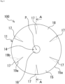
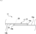
- the six fold portions 17 are disposed at equal intervals in a circumferential direction of the umbrella body 11, and are provided so as to be symmetrical with respect to a vertex P of the umbrella body 11. Furthermore, as illustrated in FIG. 4 , the fold portion 17 is formed in a substantially triangular shape (see FIG. 2 ) in plan view by being folded in a triple fold in the circumferential direction of the umbrella body 11 from an opening end 15a of the umbrella edge portion 15 to a position on the way to the umbrella top portion 14 (for example, to about any degree in a range of 1/4 to 3/4 in a vertical direction from the opening end 15a).
- the fold portion 17 includes a front surface-side fold-back portion 19a of the gore 18 and a back surface-side fold-back portion 19b of the gore 18.
- the front surface-side fold-back portion 19a is sewn to a side of a front surface 18a of the gore 18 using a parachute yarn 20 (for example, yarn made of polyamide-based fibers, yarn made of high-strength polyethylene fibers, and the like).
- the back surface-side fold-back portion 19b is sewn to a side of a back surface 18b of the gore 18 using a yarn 21 similar to the yarn 20. Note that FIG.
- a folding direction of the fold portion 17 may be a direction opposite to a direction illustrated in FIGS. 2 and 4 , or the folding directions of all the fold portions 17 may not be the same.
- the fold portion 17 is fixed at two positions using the yarns 20 and 21 and formed, but may be fixed at three or more positions and formed, or may be fixed by another method such as welding or an adhesive and formed.
- the fold portion 17 has a substantially triangular shape in plan view, but is not limited thereto, and may have, for example, an elongated substantially trapezoidal shape, a substantially quadrangular shape, or the like.
- the fold portion 17 according to the present embodiment is curved inward in a radial direction of the umbrella body 11 as illustrated in FIGS. 1 and 3 . Therefore, in the umbrella body 11, a shape in which the opening of the umbrella edge portion 15 is narrowed, that is, a three-dimensional extended skirt shape is formed. Therefore, the parachute 100 including the umbrella body 11 having the above-described configuration can improve a drag coefficient by forming the three-dimensional extended skirt shape after deployment. That is, in the parachute 100 being lowered, swinging is suppressed, and the parachute can be stably lowered.
- the fold portion 17 is folded in the triple fold, a relatively high strength is secured in the parachute 100, so that the parachute has a strength enough to withstand a line tension after the start of deployment. Therefore, a relatively thin cloth-like body can be used as the fabric of the gore 18, and the weight of the parachute 100 can be reduced. Furthermore, according to the present embodiment, since the number of the gores 18 is smaller than the number of the lines 12, it is possible to increase the size and to reduce the cost of the parachute 100.
- the parachute 100 may be applied to a safety device for reducing a risk such as a fall accident of a flight vehicle.
- the parachute 100 can be used for the safety device 200 as illustrated in FIG. 5 .
- the safety device 200 and a flight vehicle 300 provided with the safety device will be specifically described with reference to FIGS. 5 to 7 .
- the safety device 200 includes the parachute 100, a bottomed cylindrical container 201 that accommodates the parachute 100, and an ejection device 202 that is provided in the container 201 and ejects the parachute 100 to the outside of the container 201.
- the ejection device 202 includes a gas generator 203 including a cup-shaped case that accommodates an ignition charge (not illustrated), and a piston 206 including a recess 204 and a piston head 205 integrally formed with the recess 204.
- the parachute 100 is placed on the piston head 205 in a folded state.
- the parachute 100 is connected to the inside of the container 201 via the line 12 and the center cord 13, and the line 12 and the center cord 13 are folded and accommodated in the container 201 so as not to hinder the movement of the piston 206 at the time of activation. Furthermore, an opening end of the container 201 is closed by a lid 207 in an initial state, and is detached from the opening end by extrusion of the parachute 100.
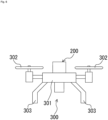
- FIG. 6 is a diagram illustrating an example of the flight vehicle 300 to which the safety device 200 is applied.
- the flight vehicle 300 includes an airframe 301, the safety device 200 provided in an upper portion of the airframe 301, one or more propulsion mechanisms (for example, propellers or the like) 302 that are coupled to the airframe 301 and propel the airframe 301, and a plurality of legs 303 provided in a lower portion of the airframe 301.
- the flight vehicle 300 according to the present embodiment is not limited to an unmanned or manned aircraft such as a drone, and also includes an aircraft such as a passenger aircraft and a helicopter.
- the piston 206 is propelled by a gas pressure generated based on an ignition operation of the gas generator 203.
- the parachute 100 can be directly pushed out and deployed by a propulsive force of the piston 206. Therefore, the parachute 100 after the deployment can suspend the flight vehicle 300 via the line 12 and the center cord 13.
- the safety device 200 includes the abnormality detection device 400 including an acceleration sensor or the like that detects an abnormality of the flight vehicle 300.
- the abnormality detection device 400 includes a sensor (detection unit) 410 and a control unit (computer including CPU, ROM, RAM, and the like) 420, and is electrically connected to an igniter in the gas generator 203 of the ejection device 202, a storage unit 401, a flight control unit 402, and an information unit 403.
- a sensor detection unit
- a control unit computer including CPU, ROM, RAM, and the like
- the sensor 410 detects a flight state (including collision, crash, etc.) of the flight vehicle 300.
- the sensor 410 is, for example, one or more sensors selected from an acceleration sensor, a gyro sensor, an atmospheric pressure sensor, a laser sensor, an infrared sensor, a vision sensor of a monocular/compound eye, an ultrasonic sensor, and the like, and can acquire data of a flight state of the flight vehicle 300, such as a speed, acceleration, inclination, altitude, and position of the flight vehicle 300, and an obstacle that may be a flight obstacle of the flight vehicle 300, data of a surrounding environment (obstacle, topography, shape of building, etc.), and the like.
- the control unit 420 includes an abnormality detection unit 421, a calculation unit 422, and a notification unit 423 as a functional configuration.
- the abnormality detection unit 421, the calculation unit 422, and the notification unit 423 are functionally implemented by the control unit 420 executing a predetermined program.
- the abnormality detection unit 421 not only detects an abnormal state related to the surrounding environment on the basis of information received from the sensor 410 but also detects a flight state of the flight vehicle (whether the flight vehicle 300 is in an abnormal state such as falling during flight). That is, the abnormality detection unit 421 detects whether or not the sensor 410 and the flight vehicle 300 are normally operable.
- the abnormality detection unit 421 can detect an emergency state of a person inside the flight vehicle 300, a fatal failure of a device inside the flight vehicle 300, a power supply of the flight vehicle 300 being less than or equal to a preset predetermined value, a fuel amount of the flight vehicle 300 being less than or equal to a preset predetermined value, an acceleration or an angular velocity of the flight vehicle 300 being greater than or equal to a predetermined value or less than or equal to a predetermined value, an attitude angle of the flight vehicle 300 being greater than or equal to a predetermined value, a descent speed of the flight vehicle 300 being greater than or equal to a predetermined value, and the like.
- the abnormality detection unit 421 can detect disappearance of an operation signal or reception of an abnormality signal from the controller. Furthermore, the abnormality detection unit 421 can detect disappearance of a signal or reception of an abnormal signal from a ground station.
- the calculation unit 422 determines whether or not the flight state of the flight vehicle 300 is abnormal on the basis of each data obtained by actual measurement by the sensor 410. Specifically, the calculation unit 422 determines an abnormality by comparing each data acquired by the sensor 410 with each preset threshold. Furthermore, the calculation unit 422 receives an obstacle detection signal, a distance detection signal, an altitude detection signal, and the like from the sensor 410 in real time, and determines an abnormality on the basis of each of these received signals. Furthermore, the calculation unit 422 determines whether the flight vehicle approaches a prohibited area, enters the prohibited area, or deviates from a planned route on the basis of the position information of the flight vehicle 300.
- the calculation unit 422 receives a signal (a periodic digital signal (rectangular wave) or a signal always in a high voltage state) from the flight control unit 402 at a constant cycle, and determines an abnormality on the basis of disappearance of this signal or disappearance/change of periodicity. Furthermore, the calculation unit 422 detects a battery voltage of the flight vehicle 300, and determines that there is an abnormality in a case where the battery voltage is less than or equal to a preset threshold.
- a signal a periodic digital signal (rectangular wave) or a signal always in a high voltage state
- the calculation unit 422 outputs an abnormality signal (which may include a command signal for starting or activating another device) to the outside.
- an abnormality signal output unit may be provided separately from the calculation unit 422, and the abnormality signal output unit may output an abnormality signal according to a command of the calculation unit 422.
- the notification unit 423 notifies an administrator or the like that the abnormality has been detected.
- the storage unit 401 can store various data such as each data acquired by the sensor 410 and determination data in a case where an abnormality is determined by the calculation unit 422.
- the flight control unit 402 controls a flight attitude of the flight vehicle 300, and can stop a propulsion device (such as a motor) provided in the flight vehicle 300 in a case where the calculation unit 422 determines an abnormality.
- a propulsion device such as a motor
- the information unit 403 can inform the surroundings of the abnormality.
- the information unit 403 activates a voice generation device (such as an alarm) and/or a lighting device (such as an LED) to inform the surroundings of the abnormality.
- the abnormality detection device 400 includes a wireless communication unit capable of communicating with the controller of the operator of the flight vehicle 300 or the ground station, when the abnormality detection unit 421 detects an abnormality of the sensor 410 and the flight vehicle 300, the information unit 403 informs the controller of the operator or the ground station of the abnormality via the wireless communication unit.
- the information unit 403 may transmit an abnormality signal to the flight control unit 402 and inform the operator's controller or the ground station of the abnormality via the wireless communication unit.
- the abnormality detection unit 421 detects an abnormal state, detects disappearance of an operation signal from the controller, or the operator operates the controller to transmit an abnormality signal to the safety device 200
- the abnormality detection unit 421 transmits an abnormality signal to the calculation unit 422.
- the calculation unit 422 Upon receiving the abnormality signal, the calculation unit 422 transmits an operation signal to the gas generator 203 of the ejection device 202.
- the gas generator 203 starts the igniter and propels the piston 206 with a generated gas pressure. With this propulsion force, the umbrella body 11 of the parachute 100 is ejected to the outside of the container 201.
- the umbrella body 11 starts to deploy, and the inflow of air to the inside of the umbrella body 11 starts.
- the fold portion 17 is curved inward in the radial direction of the umbrella body 11, a three-dimensional extended skirt shape is formed, and the umbrella body 11 is fully opened (see FIG. 1 ).
- the safety device 200 since the three-dimensional extended skirt shape is formed in the parachute 100 after deployment, the drag coefficient can be improved, and the swing of the flight vehicle 300 hung on the parachute 100 is suppressed. That is, the flight vehicle 300 can be stably lowered.
- a parachute 500 according to the second embodiment is different from that of the first embodiment in that an umbrella body 511 is configured using two gores 518a and 518b.
- the umbrella body 511 includes an umbrella top portion 514 constituting a top portion, an umbrella edge portion 515 constituting an opening, a vent 516, four first fold portions 517a, and two second fold portions 517b. Note that a line 512 is connected to each of the first fold portions 517a and each of the second fold portions 517b. Furthermore, a center cord 513 is connected to a peripheral edge portion of the vent 516.
- the umbrella body 511 includes the two gores 518a and 518b having a substantially half donut shape in plan view. Note that the linear portions of the respective gores 518a and 518b are joined together by welding, sewing, an adhesive, or the like in a state of being simply superimposed, for example, to form a connection portion 517c.
- the four first fold portions 517a are disposed at predetermined intervals in a circumferential direction of the umbrella body 511, and are provided so as to be symmetrical with respect to a vertex P of the umbrella body 511. Note that each of the first fold portions 517a is folded in a triple fold in the circumferential direction of the umbrella body 511, similarly to the fold portion 17 of the first embodiment.
- the second fold portions 517b are provided so as to face each other with the vertex P of the umbrella body 511 as a center. Furthermore, the second fold portion 517b is a connection portion formed with layers by fixing in a meshed state a portion (first hook-shaped portion) formed by folding back a lateral side portion 523a of the gore 518a from an opening end 515a of the umbrella edge portion 515 to a position on the way to the umbrella top portion 514 (for example, to about any degree in a range of 1/4 to 3/4 in a vertical direction from the opening end 515a) in the circumferential direction of the umbrella body 511 and a portion (second hook-shaped portion) formed by folding back a lateral side portion 523b of the gore 518b corresponding to (adjacent to) the lateral side portion 523a of the gore 518a in a direction opposite to a folding back direction of the gore 518a along the circumferential direction of the umbrella body 511.
- first hook-shaped portion formed by folding back a
- the second fold portion 517b is formed in a substantially triangular shape (see FIG. 8 ) in plan view from the opening end 515a of the umbrella edge portion 515 to a position on the way to the umbrella top portion 514.
- the lateral side portions 523a and 523b are sewn to the gores 518a and 518b, so that the four-layer structure of a main body of the gore 518b, the lateral side portion 523a, the lateral side portion 523b, and a main body of the gore 518a is formed and fixed from the lower part of the paper surface of FIG. 9 .
- FIG. 9 Note that FIG.
- FIG. 9 is a diagram in a case where the second fold portion 517b is viewed from the opening end 515a of the umbrella edge portion 515 on the lower side of FIG. 8 . Furthermore, the second fold portion 517b is fixed and formed at two positions using the yarns 520 and 521, but may be fixed and formed at three or more positions, or may be fixed and formed by another method such as welding or an adhesive.
- the first fold portion 517a and the second fold portion 517b according to the second embodiment are curved inward in the radial direction of the umbrella body 511 in a case where the umbrella body 511 is completely opened.
- a shape in which the opening of the umbrella edge portion 515 is narrowed that is, a three-dimensional extended skirt shape is formed. Therefore, the parachute 500 including the umbrella body 511 having the above configuration can improve the drag coefficient by forming the three-dimensional extended skirt shape after deployment. That is, in the parachute 500 being lowered, swinging is suppressed, and the parachute can be stably lowered.
- the parachute 500 is formed such that the first fold portion 517a and the second fold portion 517b are partially overlapped with each other, a relatively high strength is secured, and thus the parachute has a strength enough to withstand the line tension after the start of deployment. Therefore, a relatively thin cloth-like body can be used as the fabric of the gore 518a and 518b, and the weight of the parachute 500 can be reduced. Furthermore, according to the second embodiment, since the number of the gores 518 is smaller than the number of the lines 512, it is possible to increase the size and to reduce the cost of the parachute 500. Furthermore, the parachute 500 according to the second embodiment can be applied to a safety device (similar to the safety device 200 of the first embodiment) for reducing a risk such as a falling accident of a flight vehicle.
- a safety device similar to the safety device 200 of the first embodiment
- the fold portion may be formed by folding so as to form an odd number of layers such as a five-fold or a seven-fold in the circumferential direction of the umbrella body.
- the parachute 500 is provided with the pair of second fold portions 517b, but the present invention is not limited thereto.
- only one of the second fold portions 517b may be provided, and the other may be a connection by simple overlapping.
- the parachute 500 including the two gores 518a and 518b is shown, but the present invention is not limited thereto.
- three or more gores may be connected.
- at least one of connection portions between the lateral side portions of the gores may be similar to the second fold portion 517b.
- each line is connected one by one to a portion having a relatively high strength such as the first fold portion and the second fold portion, but the present invention is not limited thereto.
- the line may be connected to a portion other than the first fold portion and the second fold portion without necessarily connecting the line to the first fold portion and the second fold portion.
- the parachute may include a float (bag-shaped member) that functions as a floating member when landing on water.
- a float bag-shaped member
- the following modifications of the parachute are also conceivable. Note that, in the following modification, reference signs having the same numbers in the last two digits as those of the first embodiment are similar, and thus the description thereof may be omitted. Furthermore, portions that are not particularly described are similar to those of the first embodiment, and thus description and illustration thereof may be omitted.
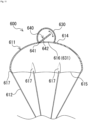
- a parachute 600 includes an umbrella body 611, a plurality of lines 612, a center cord 613, and a bag-shaped member 630.
- the bag-shaped member 630 including an intake port 631 connected to a vent 616 is provided outside an umbrella top portion 614 of the umbrella body 611, and the center cord 613 is connected to a peripheral edge portion of the vent 616 or the intake port 631.
- each of the lines 612 is connected to a fold portion 617.
- the bag-shaped member 630 when the parachute 600 is deployed, air flows into the inside of the bag-shaped member 630 from the intake port 631, the bag-shaped member 630 expands in a substantially spherical shape.
- the bag-shaped member 630 is configured by joining at least three or more polygonal (triangular, trapezoidal, etc.) or at least three or more ship-bottom shaped waterproof panel members by welding, sewing, an adhesive, or the like.
- the fabric of the waterproof panel member include a cloth-like body formed using a fiber material, a film-like body formed using a resin film and a rubber film, and the like. Note that, as a method of attaching the bag-shaped member 630 to the umbrella body 611, any one of welding, sewing, and an adhesive can be used.
- the intake port 631 of the bag-shaped member 630 is provided with a check valve 640 including a hinge portion 641 and a plate member 642.
- the plate member 642 is rotatably provided in an inner peripheral edge portion of the intake port 631 via the hinge portion 641 as indicated by an arrow in FIG. 10 .
- a rotation angle of the plate member 642 is limited so as to freely open in an internal direction of the bag-shaped member 630 via the hinge portion 641 but not to open in an external direction (not to rotate to the inside of the umbrella body 611).
- examples of the material of the plate member 642 include cloth, resin, rubber, and metal.
- the bag-shaped member 630 can be rapidly expanded, and the descent speed of the flight vehicle can be decelerated to reduce the impact on the flight vehicle at the time of landing on water. Furthermore, at the time of water landing, the inflow of air into the inside of the umbrella body 611 is stopped, and the intake port 631 is closed by the weight of the check valve 640 (in particular, the plate member 642). Therefore, the air inside the bag-shaped member 630 stays inside the bag-shaped member 630, and it is possible to suppress water from entering the bag-shaped member 630. As a result, since the bag-shaped member 630 exerts sufficient buoyancy at the time of landing on water, it is possible to prevent the flight vehicle from sinking in the water.
- the center cord 613 is provided at the vent 616 of the umbrella body 611 or the peripheral edge portion of the intake port 631 of the bag-shaped member 630, but the present invention is not limited thereto, and the center cord 613 may not be provided. That is, as illustrated in FIG. 11 , the parachute 600 of the present modification may have a configuration in which the bag-shaped member 630 functioning as a floating member at the time of landing on water is attached to the outside of the vent 616 of the umbrella body 611.
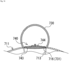
- a parachute 700 includes an umbrella body 711, a plurality of lines 712, a center cord 713, and a bag-shaped member 730.
- the bag-shaped member 730 including an intake port 731 connected to a vent 716 is provided outside an umbrella top portion 714 of the umbrella body 711, and the center cord 713 is connected to a peripheral edge portion of the vent 716 or the intake port 731.
- each of the lines 712 is connected to a fold portion 717.
- a check valve 740 including a net member 743 and a truncated cone portion 744 having a truncated cone shape when air flows in from the intake port 731 is provided in the vent 716 of the umbrella body 711 or the intake port 731 of the bag-shaped member 730.
- the net member 743 is formed in a mesh shape having air permeability, and is provided so as to cover the intake port 731.
- the truncated cone portion 744 includes an opening in each of an upper portion and a lower portion, and an opening end portion of the lower portion is attached to an edge portion of the vent 716 or the intake port 731, so that air flowing in from the vent 716 and the intake port 731 passes through the inside.
- the fabric of the truncated cone portion 744 include a cloth-like body formed using a fiber material, a film-like body formed using a resin film, and the like.
- the bag-shaped member 730 including such a check valve 740, when the parachute 700 is deployed, first, the air flowing into the umbrella body 711 flows into the truncated cone portion 744 via the vent 716, the intake port 731, and the net member 743 to form a truncated cone shape. Subsequently, the introduced air passes through the truncated cone portion 744 and is taken into the bag-shaped member 730. That is, as illustrated in FIG. 12 , the bag-shaped member 730 is in an expanded state. At the time of water landing, the inflow of air into the umbrella body 711 is stopped, and as illustrated in FIG.
- the truncated cone shape of the truncated cone portion 744 collapses and collapses due to its own weight, whereby the vent 716 and the intake port 731 are closed.
- the air inside the expanded bag-shaped member 730 can be prevented from easily coming out to the outside. Therefore, according to the parachute 700, since the bag-shaped member 730 exhibits sufficient buoyancy at the time of landing on water, it is possible to prevent the flight vehicle from sinking in the water.
- the center cord 713 may not necessarily be provided similarly to the first modification.
- a parachute 800 includes an umbrella body 811, a plurality of lines 812, a center cord 813, and a bag-shaped member 830.
- the bag-shaped member 830 including an intake port 831 connected to a vent 816 is provided outside an umbrella top portion 814 of the umbrella body 811, and the center cord 813 is connected to a peripheral edge portion of the vent 816 or the intake port 831.
- each of the lines 812 is connected to a fold portion 817.
- a check valve 840 is provided in the vent 816 of the umbrella body 811 or the intake port 831 of the bag-shaped member 830.
- the check valve 840 includes a net member 843, an inverted truncated cone portion 845 having an inverted truncated cone shape when air flows in from the intake port 831, and a plastic hollow relatively light ball 846.
- the net member 843 is formed in a mesh shape having air permeability, and is provided so as to cover an upper opening of the inverted truncated cone portion 845.
- the inverted truncated cone portion 845 includes an opening in each of an upper portion and a lower portion, and an opening end portion of the lower portion is attached to an edge portion of the vent 816 or the intake port 831, so that the air flowing in from the intake port 831 passes through the inside. Furthermore, the ball 846 is provided inside the inverted truncated cone portion 845 so as to be movable between the net member 843, and the vent 816 and the intake port 831. Note that a diameter of the ball 846 is set to be larger than a diameters of the vent 816 and the intake port 831. Furthermore, examples of the fabric of the inverted truncated cone portion 845 include a cloth-like body formed using a fiber material and a film-like body formed using a resin film.
- the bag-shaped member 830 including such a check valve 840
- the ball 846 blown by the air flowing into the umbrella body 811 moves toward the net member 843.
- air flows into the inverted truncated cone portion 845 from the vent 816 and the intake port 831 forms the inverted truncated cone shape and passes through the inverted truncated cone portion, and is taken into the bag-shaped member 830. That is, as illustrated in FIG. 14 , the bag-shaped member 830 is in an expanded state. Then, at the time of water landing, the inflow of air into the umbrella body 811 is stopped, and as illustrated in FIG.
- the inverted truncated cone shape of the inverted truncated cone portion 845 and the net member 843 collapses and collapses due to its own weight, and the ball 846 closes the vent 816 and the intake port 831.
- the air inside the expanded bag-shaped member 830 can be prevented from easily coming out to the outside. Therefore, according to the parachute 800, since the bag-shaped member 830 exhibits sufficient buoyancy at the time of landing on water, it is possible to prevent the flight vehicle from sinking in the water.
- the center cord 813 may not necessarily be provided as in the first modification.
- the vent of the umbrella body and the intake port of the bag-shaped member are formed in the same portion, but may not necessarily be formed in the same portion.
- the intake port may be attached so as to cover the outside periphery of the vent in a sealed manner, and the check valve may be attached to either the vent or the intake port.
- the flight vehicle may include an airbag device that inflates the airbag.
- the airbag device can be provided at the lower portion of the airframe in a normal attitude so as to face a main body of the safety device provided at the upper portion of the airframe in the normal attitude with the airframe interposed therebetween. In this case, the impact on the flight vehicle at the time of landing on the water can be further reduced.
- the flight vehicle may include a float disposed separately from the parachute.
- the float can be provided at the lower portion of the airframe in the normal attitude so as to face the main body of the safety device provided at the upper portion of the airframe in the normal attitude with the airframe interposed therebetween. In this case, it is possible to further prevent the flight vehicle from sinking in the water.
- a knot generally called a cow-hitch may be used as a method of attaching the line to the fold portion.
- Hibari knot a knot generally called a cow-hitch (Hibari knot)
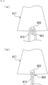
- this knotting method for example, as illustrated in a partially enlarged view of a fold portion 917 in FIG. 16(a) , first, a line 912 folded back to form an annular portion 951 is passed through a hole 952 provided on the lower end side of the fold portion 917 from above, and the annular portion 951 is pulled out from the lower end of the fold portion 917.
- the two other ends of the line 912 are passed through the drawn annular portion 951 from above and pulled downward as they are, whereby a cow-hitch portion 950 is formed as illustrated in a partially enlarged view of the fold portion 917 in FIG. 16(b) . Therefore, the line 912 is reliably connected to the fold portion 917 via the cow-hitch portion 950.
- an annular string member or a metal member may be provided at the lower end of the fold portion 917, and the line 912 may be tied to the string member or the metal member in the same procedure as described above.
- an impact-absorbing member may be adopted for the seat.
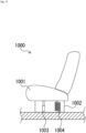
- an impact-absorbing seat 1000 provided with an impact-absorbing mechanism 1002 between a seat 1001 and a floor surface inside the flight vehicle can be used.
- the impact-absorbing mechanism 1002 includes a damper member 1003 and a spring member 1004.
- the seat 1001 is connected to a floor surface in the flight body via a damper member 1003 and a spring member 1004. In such an impact-absorbing seat 1000, an impact on the occupant at the time of landing can be reduced.
- the gas generator is adopted as the drive source of the ejection device, but the drive source is not limited thereto, and for example, an elastic body type using an elastic body such as a spring, a gas cylinder type using a gas pressure confined in a container, a chemical reaction type (non-gunpowder) in which two or more substances are mixed and chemically reacted to generate a gas pressure, or the like may be adopted.
- a pull-out type ejection device may be used instead of the ejection device of each of the embodiments and each of the modifications.
- Examples of the pull-out type ejection device include a method in which a weight is flicked by an actuator and then an object to be deployed is pulled out, a method in which a rocket is launched and an object to be deployed is pulled out, and a method in which a pilot chute is first ejected and an object to be deployed is pulled out by the pilot chute.
- the ejection device may include a piston member (sliding member), a cylinder that accommodates the piston member and is provided with a hole for the piston member to protrude outward at the time of activation, a pushing member (hat-shaped member like a hat) pushed up in one direction by the piston member, and a gas generator as a power source for moving the piston member in the cylinder.
- the gas generator is press-fitted into the lower opening end of the cylinder, and the lower portion of the cylinder is fixed to the bottom portion of the container.
- the safety device including the ejection device having such a configuration
- the piston member when the gas generator is activated when the abnormality is detected, the piston member is propelled upward in the cylinder by the pressure of the gas generated by the activation, and the pushing member connected to the piston member is propelled upward in the container.
- the lid is pushed up by the upper portion of the push-up member and removed from the opening end of the container, and the parachute placed on the flange-shaped portion of the push-up member is ejected to the outside of the container.
- the safety device includes the bottomed cylindrical container that accommodates the parachute and the ejection device, and the lid that closes the opening end of the container has been described, but the present invention is not limited thereto.
- the safety device may include a bottomed cylindrical accommodation lid (bottomed cylindrical member) that accommodates the parachute and the ejection device, and a substantially disk-shaped bottom portion that closes an opening end portion of the accommodation lid.
- the ejection device of the safety device includes a piston member (sliding member), a cylinder that accommodates the piston member and is provided with a hole through which the piston member protrudes outward at the time of activation, a base (squib holder) to which one end portion of the cylinder is caulked and fixed and which is attached via a central hole of a bottom portion, and a gas generator as a power source for moving the piston member in the cylinder.
- the accommodation lid includes a breakable portion in the vicinity of the opening end portion.
- the bottom portion includes a cylindrical protrusion extending from the edge toward the accommodation lid, and the protrusion and the side wall portion of the opening end portion of the accommodation lid can be engaged with each other using a pin member such as a brush clip pin.
- the parachute is accommodated between the inner surface of the accommodation lid and the inner surface of the bottom portion so as to surround the outer surface of the cylinder, for example.
- one end of a connection member is connected to a part of the parachute, and the other end of the connection member is connected to the inside of the accommodation lid.
- the safety device having such a configuration, when the gas generator is activated when an abnormality is detected, the piston member is propelled upward in the cylinder by the pressure of the gas generated by the activation, and the piston member abuts on the accommodation lid.
- the breakable portion of the accommodation lid is broken by the impact at the time of abutment, the opening end portion of the accommodation lid is opened, the accommodation lid is detached from the bottom portion, and the accommodation lid is ejected upward while pulling up one end of the connection member. Then, when tension is applied to the connection member, the parachute is pulled up and ejected to a side of the accommodation lid.
- the present invention is not limited thereto, and for example, the line and the center cord may be connected to the outside of the container or an airframe of the flight vehicle.
- the safety device is attached to the flight vehicle, but the present invention is not limited thereto.
- the safety device according to the present invention it is also possible to attach the safety device according to the present invention to the cargo before being dropped for use.
- a parachute 1100 called a disk band gap type parachute can also be exemplified.
- the parachute 1100 is mainly different in that an umbrella body 1111 is used instead of the umbrella body 611 in the parachute 600.
- the parachute 1100 will be described focusing on differences from the parachute 600 of the first modification. Note that, in the present modification, reference signs of the same numbers in the last two digits as those in the first embodiment or the first modification are similar to those in the first embodiment or the first modification, and thus description thereof may be omitted. Portions that are not particularly described are the same as those in the first embodiment or the first modification, and thus description and illustration thereof may be omitted.
- the umbrella body 1111 includes a lower-side gore 1118a1 that forms a lower portion of the umbrella body 1111, an upper-side gore 1118a2 that forms an upper portion of the umbrella body 1111, a line 1124 that connects the lower-side gore 1118a1 and the upper-side gore 1118a2, and a ventilation portion 1125 (six places at equal intervals in the present modification) that is surrounded between the adjacent lines 1124 and between the upper-side gore 1118a2 and the lower-side gore 1118a1 and becomes a vent hole for air after deployment. That is, the umbrella body 1111 is different from the umbrella body 611 in the parachute 600 in that the line 1124 and the ventilation portion 1125 are provided.
- One end portion of the line 1124 is fixed to a fold portion 1117 by sewing or the like, and the other end portion is fixed to the upper-side gore 1118a2 by sewing or the like.
- Six lines 1124 of the present modification are disposed side by side at equal intervals in the circumferential direction.
- the ventilation portion 1125 is provided in the umbrella body 1111, the air flowing into the inside of the umbrella body 1111 after the deployment passes through the ventilation portion 1125, it is possible to suppress the pendulum motion (oscillation) of the parachute 1100.
- a parachute 1200 illustrated in FIGS. 20 to 22 can also be exemplified.
- the parachute 1200 of the present modification is different from the parachute 500 of the second embodiment mainly in that the first fold portion 517a, the second fold portion 517b, and the connection portion 517c in the parachute of the second embodiment are a connection portion 1217a, a connection portion 1217b (first fixation portion), and a connection portion 1217c (second fixation portion).
- the parachute 1200 will be described focusing on differences from the parachute 500 of the second embodiment.
- connection portions 1217a, 1217b, and 1217c are different from the first fold portion 517a, the second fold portion 517b, and the connection portion 517c in this order in the parachute 500 of the second embodiment in the connection method and the connection structure.
- connection portion 1217a is formed in a portion (including a portion where the lateral side portions 1218a2 and 1218a2 are overlapped (see FIG. 21 )) from the umbrella edge portion 1215 of the umbrella body 1211 to a position on the way to the umbrella top portion 1214.
- connection portion 1217b is formed in a portion (including a portion where the lateral side portions 1218a2 and 1218b2 are overlapped (see FIG. 21 )) from the umbrella edge portion 1215 of the umbrella body 1211 to a position on the way to the umbrella top portion 1214.
- FIG. 21 the connection portion 1217a is formed in a portion (including a portion where the lateral side portions 1218a2 and 1218a2 are overlapped (see FIG. 21 )) from the umbrella edge portion 1215 of the umbrella body 1211 to a position on the way to the umbrella top portion 1214.
- connection portion 1217c is formed in a portion (including a portion where the lateral side portions 1218a1 and 1218b1 are overlapped (see FIG. 21 )) from a portion from the umbrella edge portion 1215 up to a position on the way to the umbrella top portion 1214 to the umbrella top portion 1214.
- the opening of the umbrella body 1211 is formed such that a portion (portion including connection portions 1217a and 1217b) from the umbrella edge portion 1215 to a position on the way to the umbrella top portion 1214 is inclined inward in the radial direction of the umbrella body 1211 in a case where the umbrella body 1211 is opened with respect to a portion (a portion including the connection portion 1217c) from the position on the way to the umbrella top portion 1214 to the umbrella top portion 1214 so as to form a recessed shape, that is, a three-dimensional extended skirt shape.
- connection step of the connection portion 1217c will be described.
- the step of connecting the connection portions 1217a and 1217b is substantially the same as the step of connecting the connection portion 1217c, and thus the description thereof will be omitted.
- two gores 1218a and 1218b having the same shape are cut out from a sheet (cloth or the like) for parachute, and then a reinforcement tape 1224 is attached to an end of each gore to reinforce the end (see FIG. 21 ).
- the gores 1218a and 1218b are overlapped so that the positions of the lateral side portions 1218a1 and 1218b1 of the gores 1218a and 1218b coincide with each other (see FIG. 22(a) ).
- the gores 1218a and 1218b is sewn and fixed using yarns 1226 and 1227.
- this fixing may be performed using another fixing method such as welding or an adhesive.
- the lateral side portions 1218a1 and 1218b1 of the gores 1218a and 1218b are folded back in the circumferential direction of the umbrella body 1211 so that the gore 1218a is on the inner side to form a back surface-side fold-back portion 1222b (see FIG. 22(b) ).
- the gores 1218a and 1218b since the gores 1218a and 1218b has already been sewn and fixed using the yarns 1226 and 1227, the gores 1218a and 1218b is less likely to be displaced.
- the gore 1218a and 1218b are entirely sewn and fixed again using a yarn 1228 at a position corresponding to the sewing position of the yarn 1226 (see FIG. 22(d) ).
- the gores 1218a and 1218b are again sewn and fixed using a yarn 1229 at a position corresponding to the sewing position of the yarn 1227 (see FIG. 22(d) ).
- the five-layer connection portion 1217c is formed.
- the reinforcement tape 1224 is a reinforcement member that is appropriately provided in a portion requiring reinforcement, such as a portion to which a load is applied by a line (not illustrated) connected to the annular member 1225.
- the annular member 1225 has an annular portion such that a cow-hitch can be attached to a line (not illustrated), and a part thereof is fixed to the connection portions 1217a and 1217b by sewing or an adhesive.
- the gore when the connection portions 1217a and 1217b, and 1217c of the gore 1218a and 1218b are formed, the gore can be sewn so as not to be displaced from each other. That is, since the parachute 1200 can be easily manufactured, the manufacturing cost can be suppressed as compared with other parachutes.
Landscapes
- Engineering & Computer Science (AREA)
- Aviation & Aerospace Engineering (AREA)
- Walking Sticks, Umbrellas, And Fans (AREA)
- Emergency Lowering Means (AREA)
Abstract
Description
- The present invention relates to a parachute, and a safety device and a flight vehicle provided with the parachute.
- Conventionally, a parachute has been widely used to lower a flight vehicle or a falling object falling from the flight vehicle. Furthermore, the parachute is also used as a safety device for reducing a risk of a drop accident of a drone (flight vehicle). For example, Patent Literature 1 discloses a parachute including an umbrella body formed by connecting a plurality of panels (gore) and the same number of lines as the number of panels.
- Patent Literature 1:
US 2004/0026568 A - However, in Patent Literature 1, in a case where the parachute is used for a relatively large flight vehicle, an umbrella body having a size in accordance with the flight vehicle is required. That is, in the parachute of Patent Literature 1, as the umbrella body is increased in size, the number of panels and the number of lines are increased. Therefore, there is a problem that man-hours such as sewing for connecting the adjacent panels and man-hours for connecting the line and the panel increase, leading to an increase in cost. On the other hand, in the parachute in which the number of panels is smaller than the number of lines, in a case where cloth is used for the fabric of the umbrella body, strength enough to withstand a line tension applied to one piece of cloth is required, and there is a problem that it is difficult to increase the size of the umbrella body.
- Therefore, the present invention has been made in view of such circumstances, and an object of the present invention is to provide a parachute that can improve the strength as compared with the conventional parachute even though the number of panels is relatively small, and can be increased in size at low cost, and a safety device and a flight vehicle provided with the parachute.
-
- (1) A parachute of the present invention includes: an umbrella body including an umbrella top portion and an umbrella edge portion; and a plurality of lines including one ends connected to the umbrella body, in which the umbrella body is formed of one or more gores, and at least one first fold portion formed with layers by folding and fixing a portion along a circumferential direction in a range from the umbrella edge portion to a position on a way to the umbrella top portion so as to form an odd number of layers in the circumferential direction of the umbrella body is provided.
- (2) As another aspect, a parachute of the present invention may include: an umbrella body including an umbrella top portion and an umbrella edge portion; and a plurality of lines including one ends connected to the umbrella body, in which the umbrella body may be formed by connecting lateral side portions of a plurality of gores in a circumferential direction, and at least one of the connection portions between each of the gores and a gore adjacent to the each of the gores (hereinafter, adjacent gore) may be provided with a fold portion formed with layers by fixing in a meshed state: a first hook-shaped portion formed by folding back a portion of a lateral side portion of the gore from the umbrella edge portion to a position on a way to the umbrella top portion in a circumferential direction of the umbrella body; and a second hook-shaped portion formed by folding back a portion of a lateral side portion of the adjacent gore that corresponds to the first hook-shaped portion in a direction opposite to a folding back direction of the gore along the circumferential direction of the umbrella body.
- (3) As still another aspect, a parachute of the present invention may include: an umbrella body including an umbrella top portion and an umbrella edge portion; and a plurality of lines including one ends connected to the umbrella body, in which the umbrella body may be formed by connecting lateral side portions of a plurality of gore in a circumferential direction, at least one of the connection portions between each of the gores and a gore adjacent to the each of the gores (hereinafter, adjacent gore) may be provided with: a first fixation portion formed by folding back the gore and the adjacent gore in a circumferential direction of the umbrella body to form a fold-back portion in a state where the gore and the adjacent gore are overlapped and a portion out of each lateral side portion of the gore and the adjacent gore from the umbrella edge portion to a position on a way to the umbrella top portion is fixed, and fixing the gore corresponding to a position of the fold-back portion and the adjacent gore after folding back only the gore or the adjacent gore that is on an inner side in a direction opposite to a folding back direction of the fold-back portion so as to overlap the fold-back portion; and/or a second fixation portion formed by folding back the gore and the adjacent gore in a circumferential direction of the umbrella body to form a fold-back portion in a state where the gore and the adjacent gore are overlapped and a portion out of each lateral side portion of the gore and the adjacent gore from a portion at a position on a way to the umbrella top portion from the umbrella edge portion to the umbrella top portion is fixed, and fixing the gore corresponding to a position of the fold-back portion and the adjacent gore after folding back only the gore or the adjacent gore that is on an inner side in a direction opposite to a folding back direction of the fold-back portion so as to overlap the fold-back portion, and the portion from the umbrella edge portion to a position on a way to the umbrella top portion may be formed so as to be inclined inward in a radial direction of the umbrella body in a case where the umbrella body is opened with respect to the portion from a portion at a position on a way to the umbrella top portion from the umbrella edge portion to the umbrella top portion so that an opening portion on a side of the lines of the umbrella body has a narrowed shape.
- (4) In the parachutes of (1) to (3) described above, it is preferable that one end of one line of the plurality of lines is connected to the fold portion.
- (5) In the parachutes of (1) to (3) described above, the number of the gores is preferably less than the number of the lines.
- (6) In the parachute of (1) to (3) described above, it is preferable that a vent opened at a time of deployment is formed in the umbrella top portion, and a bag-shaped member including an intake port that takes in air through the vent is provided on an outer side of the vent.
- (7) In the parachute of (6) described above, it is preferable that the parachute further includes a center cord including one end branched into a plurality of portions from a middle and connected to an edge portion of the vent.
- (8) A safety device of the present invention includes: the parachute according to any one of (1) to (3) described above; a container that accommodates the parachute; and an ejection device that is provided in the container and ejects the parachute to an outside of the container.
- (9) In the safety device of (8) described above, preferably, the safety device is attachable to a flight vehicle, and further includes an abnormality detection device capable of detecting an abnormality of the flight vehicle or a surrounding environment, in which the abnormality detection device activates the ejection device in a case of detecting the abnormality.
- (10) The safety device of (9) described above preferably further includes a flight control unit that stops a propulsion device provided in the flight vehicle in a case where the abnormality detection device detects the abnormality.
- (11) A flight vehicle of the present invention includes: an airframe; the safety device according to (8) described above, the safety device being provided in the airframe; and one or more propulsion mechanisms coupled to the airframe to propel the airframe.
- According to the present invention, it is possible to provide a parachute capable of improving the strength as compared with the conventional parachute even though the number of panels is relatively small, and capable of increasing the size at low cost, and a safety device and a flight vehicle provided with the parachute.
-
-
FIG. 1 is a perspective view illustrating a state after deployment of a parachute according to a first embodiment of the present invention. -
FIG. 2 is a plan view of the parachute inFIG. 1 . -
FIG. 3 is a schematic cross-sectional view taken along line A-A inFIG. 2 . -
FIG. 4 is a diagram illustrating how to fold a fold portion in the parachute ofFIG. 1 . -
FIG. 5 is a schematic cross-sectional view illustrating a safety device according to the first embodiment. -
FIG. 6 is a diagram illustrating a flight vehicle to which the safety device ofFIG. 5 is applied. -
FIG. 7 is a block diagram illustrating a functional configuration of the safety device ofFIG. 5 . -
FIG. 8 is a plan view of a parachute according to a second embodiment of the present invention. -
FIG. 9 is a diagram illustrating how to fold a second fold portion in the parachute ofFIG. 8 . -
FIG. 10 is a schematic cross-sectional view illustrating an example of a parachute according to a first modification of the present invention. -
FIG. 11 is a schematic cross-sectional view illustrating another example of the parachute according to the first modification of the present invention. -
FIG. 12 is a schematic cross-sectional view illustrating a parachute according to a second modification of the present invention. -
FIG. 13 is a schematic partially enlarged cross-sectional view illustrating a state of a check valve after landing on water in the parachute ofFIG. 12 . -
FIG. 14 is a schematic cross-sectional view illustrating a parachute according to a third modification of the present invention. -
FIG. 15 is a schematic partially enlarged cross-sectional view illustrating a state of a check valve after landing on water in the parachute ofFIG. 14 . -
FIG. 16 is a diagram illustrating an example of a method of attaching a line to a fold portion in the present invention. -
FIG. 17 is a diagram illustrating an example of an impact-absorbing seat applied to a flight vehicle in the present invention. -
FIG. 18 is a plan view illustrating a modification of the parachute illustrated inFIG. 10 . -
FIG. 19 is a schematic cross-sectional view taken along line B-B inFIG. 18 . -
FIG. 20 is a perspective view of a parachute according to a modification of the second embodiment of the present invention. -
FIG. 21 is a plan view illustrating a gore that is a component of an umbrella body of the parachute ofFIG. 20 . -
FIG. 22 is a process diagram explaining a connection step of a connection portion of the umbrella body of the parachute inFIG. 20 . - Hereinafter, a parachute according to an embodiment of the present invention will be described with reference to the drawings.
- As illustrated in
FIG. 1 , aparachute 100 according to the present embodiment includes anumbrella body 11, a plurality of (six in the present embodiment)lines 12, and acenter cord 13. - As illustrated in
FIGS. 1 and2 , theumbrella body 11 includes an umbrellatop portion 14 constituting a top portion, anumbrella edge portion 15 constituting an opening, avent 16, and a plurality of (six in the present embodiment) fold portions 17 (first fold portions). Furthermore, theumbrella body 11 is formed of onegore 18 having a substantially donut shape in plan view, and a cloth-like body made of a fiber material is used as a fabric of thegore 18. Furthermore, thevent 16 is provided in the umbrellatop portion 14, and as illustrated inFIG. 3 , thecenter cord 13 is connected to a peripheral edge portion of thevent 16. Note that, when opening of theumbrella body 11 is started, tension is applied to thecenter cord 13, so that thevent 16 is easily opened. Furthermore, in a case where theumbrella body 11 is completely opened, the tension of thecenter cord 13 is applied to the peripheral edge portion of thevent 16, so that theumbrella body 11 has a shape in which the umbrellatop portion 14 is recessed as illustrated inFIG. 3 . - Each of the
lines 12 is a cord-like connection member including one end connected to thefold portion 17 and the other end connected to the inside of acontainer 201 of asafety device 200 described later. Note that examples of a method of attaching theline 12 to thefold portion 17 include welding, sewing, and an adhesive. Furthermore, the one end of theline 12 may be connected to any position on the outer side, the inner side, or between layers of thefold portion 17. - The
center cord 13 is a cable-like connection member including one end branched into a plurality of portions from the middle and connected to the peripheral edge portion of thevent 16, and the other end connected to the inside of thecontainer 201 of thesafety device 200 to be described later. Note that examples of a method of attaching thecenter cord 13 to the peripheral edge portion of thevent 16 include welding, sewing, and an adhesive. - As illustrated in
FIG. 2 , the sixfold portions 17 are disposed at equal intervals in a circumferential direction of theumbrella body 11, and are provided so as to be symmetrical with respect to a vertex P of theumbrella body 11. Furthermore, as illustrated inFIG. 4 , thefold portion 17 is formed in a substantially triangular shape (seeFIG. 2 ) in plan view by being folded in a triple fold in the circumferential direction of theumbrella body 11 from an openingend 15a of theumbrella edge portion 15 to a position on the way to the umbrella top portion 14 (for example, to about any degree in a range of 1/4 to 3/4 in a vertical direction from the openingend 15a). That is, thefold portion 17 includes a front surface-side fold-back portion 19a of thegore 18 and a back surface-side fold-back portion 19b of thegore 18. The front surface-side fold-back portion 19a is sewn to a side of afront surface 18a of thegore 18 using a parachute yarn 20 (for example, yarn made of polyamide-based fibers, yarn made of high-strength polyethylene fibers, and the like). Furthermore, the back surface-side fold-back portion 19b is sewn to a side of aback surface 18b of thegore 18 using ayarn 21 similar to theyarn 20. Note thatFIG. 4 is a diagram in a case where thefold portion 17 is viewed from a lower portion of the openingend 15a of theumbrella edge portion 15 inFIG. 2 . Furthermore, a folding direction of thefold portion 17 may be a direction opposite to a direction illustrated inFIGS. 2 and4 , or the folding directions of all thefold portions 17 may not be the same. Furthermore, thefold portion 17 is fixed at two positions using theyarns fold portion 17 has a substantially triangular shape in plan view, but is not limited thereto, and may have, for example, an elongated substantially trapezoidal shape, a substantially quadrangular shape, or the like. - In a case where the
umbrella body 11 is completely opened, thefold portion 17 according to the present embodiment is curved inward in a radial direction of theumbrella body 11 as illustrated inFIGS. 1 and3 . Therefore, in theumbrella body 11, a shape in which the opening of theumbrella edge portion 15 is narrowed, that is, a three-dimensional extended skirt shape is formed. Therefore, theparachute 100 including theumbrella body 11 having the above-described configuration can improve a drag coefficient by forming the three-dimensional extended skirt shape after deployment. That is, in theparachute 100 being lowered, swinging is suppressed, and the parachute can be stably lowered. - Furthermore, since the
fold portion 17 is folded in the triple fold, a relatively high strength is secured in theparachute 100, so that the parachute has a strength enough to withstand a line tension after the start of deployment. Therefore, a relatively thin cloth-like body can be used as the fabric of thegore 18, and the weight of theparachute 100 can be reduced. Furthermore, according to the present embodiment, since the number of thegores 18 is smaller than the number of thelines 12, it is possible to increase the size and to reduce the cost of theparachute 100. - Furthermore, the
parachute 100 according to the embodiment of the present invention may be applied to a safety device for reducing a risk such as a fall accident of a flight vehicle. For example, theparachute 100 can be used for thesafety device 200 as illustrated inFIG. 5 . Hereinafter, thesafety device 200 and aflight vehicle 300 provided with the safety device will be specifically described with reference toFIGS. 5 to 7 . - As illustrated in
FIG. 5 , thesafety device 200 according to the present embodiment includes theparachute 100, a bottomedcylindrical container 201 that accommodates theparachute 100, and anejection device 202 that is provided in thecontainer 201 and ejects theparachute 100 to the outside of thecontainer 201. Here, theejection device 202 includes agas generator 203 including a cup-shaped case that accommodates an ignition charge (not illustrated), and apiston 206 including arecess 204 and apiston head 205 integrally formed with therecess 204. Furthermore, theparachute 100 is placed on thepiston head 205 in a folded state. Note that, in thesafety device 200 before activation, theparachute 100 is connected to the inside of thecontainer 201 via theline 12 and thecenter cord 13, and theline 12 and thecenter cord 13 are folded and accommodated in thecontainer 201 so as not to hinder the movement of thepiston 206 at the time of activation. Furthermore, an opening end of thecontainer 201 is closed by alid 207 in an initial state, and is detached from the opening end by extrusion of theparachute 100. -
FIG. 6 is a diagram illustrating an example of theflight vehicle 300 to which thesafety device 200 is applied. Theflight vehicle 300 includes anairframe 301, thesafety device 200 provided in an upper portion of theairframe 301, one or more propulsion mechanisms (for example, propellers or the like) 302 that are coupled to theairframe 301 and propel theairframe 301, and a plurality oflegs 303 provided in a lower portion of theairframe 301. Furthermore, theflight vehicle 300 according to the present embodiment is not limited to an unmanned or manned aircraft such as a drone, and also includes an aircraft such as a passenger aircraft and a helicopter. - In such a configuration, when an abnormality is detected by an
abnormality detection device 400 to be described later, thepiston 206 is propelled by a gas pressure generated based on an ignition operation of thegas generator 203. As a result, theparachute 100 can be directly pushed out and deployed by a propulsive force of thepiston 206. Therefore, theparachute 100 after the deployment can suspend theflight vehicle 300 via theline 12 and thecenter cord 13. - Furthermore, the
safety device 200 includes theabnormality detection device 400 including an acceleration sensor or the like that detects an abnormality of theflight vehicle 300. - Here, a functional configuration of the
abnormality detection device 400 will be described. As illustrated inFIG. 7 , theabnormality detection device 400 includes a sensor (detection unit) 410 and a control unit (computer including CPU, ROM, RAM, and the like) 420, and is electrically connected to an igniter in thegas generator 203 of theejection device 202, astorage unit 401, aflight control unit 402, and aninformation unit 403. - The
sensor 410 detects a flight state (including collision, crash, etc.) of theflight vehicle 300. Specifically, thesensor 410 is, for example, one or more sensors selected from an acceleration sensor, a gyro sensor, an atmospheric pressure sensor, a laser sensor, an infrared sensor, a vision sensor of a monocular/compound eye, an ultrasonic sensor, and the like, and can acquire data of a flight state of theflight vehicle 300, such as a speed, acceleration, inclination, altitude, and position of theflight vehicle 300, and an obstacle that may be a flight obstacle of theflight vehicle 300, data of a surrounding environment (obstacle, topography, shape of building, etc.), and the like. - The
control unit 420 includes anabnormality detection unit 421, acalculation unit 422, and anotification unit 423 as a functional configuration. Theabnormality detection unit 421, thecalculation unit 422, and thenotification unit 423 are functionally implemented by thecontrol unit 420 executing a predetermined program. - The
abnormality detection unit 421 not only detects an abnormal state related to the surrounding environment on the basis of information received from thesensor 410 but also detects a flight state of the flight vehicle (whether theflight vehicle 300 is in an abnormal state such as falling during flight). That is, theabnormality detection unit 421 detects whether or not thesensor 410 and theflight vehicle 300 are normally operable. For example, theabnormality detection unit 421 can detect an emergency state of a person inside theflight vehicle 300, a fatal failure of a device inside theflight vehicle 300, a power supply of theflight vehicle 300 being less than or equal to a preset predetermined value, a fuel amount of theflight vehicle 300 being less than or equal to a preset predetermined value, an acceleration or an angular velocity of theflight vehicle 300 being greater than or equal to a predetermined value or less than or equal to a predetermined value, an attitude angle of theflight vehicle 300 being greater than or equal to a predetermined value, a descent speed of theflight vehicle 300 being greater than or equal to a predetermined value, and the like. Furthermore, in a case where theflight vehicle 300 is operated by an operator using a controller, theabnormality detection unit 421 can detect disappearance of an operation signal or reception of an abnormality signal from the controller. Furthermore, theabnormality detection unit 421 can detect disappearance of a signal or reception of an abnormal signal from a ground station. - The
calculation unit 422 determines whether or not the flight state of theflight vehicle 300 is abnormal on the basis of each data obtained by actual measurement by thesensor 410. Specifically, thecalculation unit 422 determines an abnormality by comparing each data acquired by thesensor 410 with each preset threshold. Furthermore, thecalculation unit 422 receives an obstacle detection signal, a distance detection signal, an altitude detection signal, and the like from thesensor 410 in real time, and determines an abnormality on the basis of each of these received signals. Furthermore, thecalculation unit 422 determines whether the flight vehicle approaches a prohibited area, enters the prohibited area, or deviates from a planned route on the basis of the position information of theflight vehicle 300. - Furthermore, the
calculation unit 422 receives a signal (a periodic digital signal (rectangular wave) or a signal always in a high voltage state) from theflight control unit 402 at a constant cycle, and determines an abnormality on the basis of disappearance of this signal or disappearance/change of periodicity. Furthermore, thecalculation unit 422 detects a battery voltage of theflight vehicle 300, and determines that there is an abnormality in a case where the battery voltage is less than or equal to a preset threshold. - Furthermore, in the case of determining that the flight state of the
flight vehicle 300 is abnormal, thecalculation unit 422 outputs an abnormality signal (which may include a command signal for starting or activating another device) to the outside. Note that an abnormality signal output unit may be provided separately from thecalculation unit 422, and the abnormality signal output unit may output an abnormality signal according to a command of thecalculation unit 422. - In a case where the
abnormality detection unit 421 detects an abnormality in thesensor 410 and theflight vehicle 300, thenotification unit 423 notifies an administrator or the like that the abnormality has been detected. - The
storage unit 401 can store various data such as each data acquired by thesensor 410 and determination data in a case where an abnormality is determined by thecalculation unit 422. - The
flight control unit 402 controls a flight attitude of theflight vehicle 300, and can stop a propulsion device (such as a motor) provided in theflight vehicle 300 in a case where thecalculation unit 422 determines an abnormality. - In a case where the
calculation unit 422 determines an abnormality, theinformation unit 403 can inform the surroundings of the abnormality. For example, theinformation unit 403 activates a voice generation device (such as an alarm) and/or a lighting device (such as an LED) to inform the surroundings of the abnormality. Furthermore, in a case where theabnormality detection device 400 includes a wireless communication unit capable of communicating with the controller of the operator of theflight vehicle 300 or the ground station, when theabnormality detection unit 421 detects an abnormality of thesensor 410 and theflight vehicle 300, theinformation unit 403 informs the controller of the operator or the ground station of the abnormality via the wireless communication unit. Furthermore, when theabnormality detection unit 421 detects an abnormality in thesensor 410 and theflight vehicle 300, theinformation unit 403 may transmit an abnormality signal to theflight control unit 402 and inform the operator's controller or the ground station of the abnormality via the wireless communication unit. - Next, an operation of the
safety device 200 will be described. - First, in a case where the
flight vehicle 300 is in an abnormal situation during flight, when theabnormality detection unit 421 detects an abnormal state, detects disappearance of an operation signal from the controller, or the operator operates the controller to transmit an abnormality signal to thesafety device 200, theabnormality detection unit 421 transmits an abnormality signal to thecalculation unit 422. Upon receiving the abnormality signal, thecalculation unit 422 transmits an operation signal to thegas generator 203 of theejection device 202. Upon receipt of this operation signal, thegas generator 203 starts the igniter and propels thepiston 206 with a generated gas pressure. With this propulsion force, theumbrella body 11 of theparachute 100 is ejected to the outside of thecontainer 201. Then, the plurality oflines 12 and thecenter cord 13 connected to the ejectedumbrella body 11 extend, theumbrella body 11 starts to deploy, and the inflow of air to the inside of theumbrella body 11 starts. Thereafter, after thelines 12 and thecenter cord 13 are fully extended and stretched, that is, after thelines 12 and thecenter cord 13 are tensioned, thefold portion 17 is curved inward in the radial direction of theumbrella body 11, a three-dimensional extended skirt shape is formed, and theumbrella body 11 is fully opened (seeFIG. 1 ). - Therefore, according to the
safety device 200, since the three-dimensional extended skirt shape is formed in theparachute 100 after deployment, the drag coefficient can be improved, and the swing of theflight vehicle 300 hung on theparachute 100 is suppressed. That is, theflight vehicle 300 can be stably lowered. - Next, a parachute according to a second embodiment will be described with reference to
FIGS. 8 and9 . Note that, in the present embodiment, reference signs having the same numbers in the last two digits as those in the first embodiment are similar, and thus the description thereof may be omitted. Furthermore, portions that are not particularly described are similar to those of the first embodiment, and thus description and illustration thereof may be omitted. - As illustrated in
FIG. 8 , aparachute 500 according to the second embodiment is different from that of the first embodiment in that anumbrella body 511 is configured using twogores - The
umbrella body 511 includes an umbrellatop portion 514 constituting a top portion, anumbrella edge portion 515 constituting an opening, avent 516, fourfirst fold portions 517a, and twosecond fold portions 517b. Note that a line 512 is connected to each of thefirst fold portions 517a and each of thesecond fold portions 517b. Furthermore, a center cord 513 is connected to a peripheral edge portion of thevent 516. - As illustrated in
FIG. 8 , theumbrella body 511 includes the twogores respective gores connection portion 517c. - The four
first fold portions 517a are disposed at predetermined intervals in a circumferential direction of theumbrella body 511, and are provided so as to be symmetrical with respect to a vertex P of theumbrella body 511. Note that each of thefirst fold portions 517a is folded in a triple fold in the circumferential direction of theumbrella body 511, similarly to thefold portion 17 of the first embodiment. - The
second fold portions 517b are provided so as to face each other with the vertex P of theumbrella body 511 as a center. Furthermore, thesecond fold portion 517b is a connection portion formed with layers by fixing in a meshed state a portion (first hook-shaped portion) formed by folding back alateral side portion 523a of thegore 518a from an openingend 515a of theumbrella edge portion 515 to a position on the way to the umbrella top portion 514 (for example, to about any degree in a range of 1/4 to 3/4 in a vertical direction from the openingend 515a) in the circumferential direction of theumbrella body 511 and a portion (second hook-shaped portion) formed by folding back alateral side portion 523b of thegore 518b corresponding to (adjacent to) thelateral side portion 523a of thegore 518a in a direction opposite to a folding back direction of thegore 518a along the circumferential direction of theumbrella body 511. Furthermore, as illustrated inFIG. 9 , thesecond fold portion 517b is formed in a substantially triangular shape (seeFIG. 8 ) in plan view from the openingend 515a of theumbrella edge portion 515 to a position on the way to the umbrellatop portion 514. Note that, by usingyarns yarn 20 of the first embodiment, thelateral side portions gores gore 518b, thelateral side portion 523a, thelateral side portion 523b, and a main body of thegore 518a is formed and fixed from the lower part of the paper surface ofFIG. 9 . Note thatFIG. 9 is a diagram in a case where thesecond fold portion 517b is viewed from the openingend 515a of theumbrella edge portion 515 on the lower side ofFIG. 8 . Furthermore, thesecond fold portion 517b is fixed and formed at two positions using theyarns - The
first fold portion 517a and thesecond fold portion 517b according to the second embodiment are curved inward in the radial direction of theumbrella body 511 in a case where theumbrella body 511 is completely opened. Thus, in theumbrella body 511, a shape in which the opening of theumbrella edge portion 515 is narrowed, that is, a three-dimensional extended skirt shape is formed. Therefore, theparachute 500 including theumbrella body 511 having the above configuration can improve the drag coefficient by forming the three-dimensional extended skirt shape after deployment. That is, in theparachute 500 being lowered, swinging is suppressed, and the parachute can be stably lowered. - Furthermore, since the
parachute 500 is formed such that thefirst fold portion 517a and thesecond fold portion 517b are partially overlapped with each other, a relatively high strength is secured, and thus the parachute has a strength enough to withstand the line tension after the start of deployment. Therefore, a relatively thin cloth-like body can be used as the fabric of thegore parachute 500 can be reduced. Furthermore, according to the second embodiment, since the number of the gores 518 is smaller than the number of the lines 512, it is possible to increase the size and to reduce the cost of theparachute 500. Furthermore, theparachute 500 according to the second embodiment can be applied to a safety device (similar to thesafety device 200 of the first embodiment) for reducing a risk such as a falling accident of a flight vehicle. - Although the embodiments of the present invention have been described above, it is merely an example, and the present invention is not particularly limited, and the specific configuration and the like can be modified in design as appropriate. Furthermore, the actions and effects described in the embodiments of the present invention merely enumerate the most suitable actions and effects resulting from the present invention, and the actions and effects according to the present invention are not limited to those described in the embodiments of the present invention.
- In each of the above embodiments, the case where the center cord is connected to the peripheral edge portion of the vent of the umbrella body has been described, but the center cord may not necessarily be provided in the parachute.
- Furthermore, in each of the above embodiments, the description has been given of the case where the six fold portions are provided so as to be positioned on a side of the opening end of the umbrella edge portion in the circumferential direction of the umbrella body, but the present invention is not limited thereto, and at least one fold portion may be provided at a position including the umbrella edge portion and not in contact with the vent of the umbrella top portion. Furthermore, in each of the above embodiments, the case where the first fold portion is folded in the triple fold in the circumferential direction of the umbrella body has been described, but the present invention is not limited thereto. For example, the fold portion may be formed by folding so as to form an odd number of layers such as a five-fold or a seven-fold in the circumferential direction of the umbrella body.
- Furthermore, in the second embodiment, the
parachute 500 is provided with the pair ofsecond fold portions 517b, but the present invention is not limited thereto. For example, only one of thesecond fold portions 517b may be provided, and the other may be a connection by simple overlapping. - Furthermore, in the second embodiment, the
parachute 500 including the twogores second fold portion 517b. - Furthermore, in each of the above embodiments, each line is connected one by one to a portion having a relatively high strength such as the first fold portion and the second fold portion, but the present invention is not limited thereto. For example, in a case where the strength of the gore itself is sufficiently high, the line may be connected to a portion other than the first fold portion and the second fold portion without necessarily connecting the line to the first fold portion and the second fold portion.
- Furthermore, in each of the above embodiments, the parachute may include a float (bag-shaped member) that functions as a floating member when landing on water. For example, the following modifications of the parachute are also conceivable. Note that, in the following modification, reference signs having the same numbers in the last two digits as those of the first embodiment are similar, and thus the description thereof may be omitted. Furthermore, portions that are not particularly described are similar to those of the first embodiment, and thus description and illustration thereof may be omitted.
- As illustrated in
FIG. 10 , aparachute 600 according to a first modification includes anumbrella body 611, a plurality oflines 612, acenter cord 613, and a bag-shapedmember 630. Note that the bag-shapedmember 630 including anintake port 631 connected to avent 616 is provided outside an umbrellatop portion 614 of theumbrella body 611, and thecenter cord 613 is connected to a peripheral edge portion of thevent 616 or theintake port 631. Furthermore, each of thelines 612 is connected to afold portion 617. - Furthermore, when the
parachute 600 is deployed, air flows into the inside of the bag-shapedmember 630 from theintake port 631, the bag-shapedmember 630 expands in a substantially spherical shape. Furthermore, the bag-shapedmember 630 is configured by joining at least three or more polygonal (triangular, trapezoidal, etc.) or at least three or more ship-bottom shaped waterproof panel members by welding, sewing, an adhesive, or the like. Here, examples of the fabric of the waterproof panel member include a cloth-like body formed using a fiber material, a film-like body formed using a resin film and a rubber film, and the like. Note that, as a method of attaching the bag-shapedmember 630 to theumbrella body 611, any one of welding, sewing, and an adhesive can be used. - Furthermore, as illustrated in
FIG. 10 , theintake port 631 of the bag-shapedmember 630 is provided with acheck valve 640 including ahinge portion 641 and aplate member 642. Theplate member 642 is rotatably provided in an inner peripheral edge portion of theintake port 631 via thehinge portion 641 as indicated by an arrow inFIG. 10 . Note that a rotation angle of theplate member 642 is limited so as to freely open in an internal direction of the bag-shapedmember 630 via thehinge portion 641 but not to open in an external direction (not to rotate to the inside of the umbrella body 611). Note that examples of the material of theplate member 642 include cloth, resin, rubber, and metal. - In such a bag-shaped
member 630, when theparachute 600 is deployed, the edge portions of thevent 616 and theintake port 631 are pulled to the lower side ofFIG. 10 by thecenter cord 613 and are pulled radially outward from a center by theline 612, so that thecheck valve 640 provided in theintake port 631 can be opened and closed. Then, theplate member 642 is pushed toward the inside of the bag-shapedmember 630 by further inflow of air into theumbrella body 611, theintake port 631 is opened, the air naturally flows into the bag-shapedmember 630, and the bag-shapedmember 630 expands and deploys in a substantially spherical shape. - Therefore, in the
parachute 600, the bag-shapedmember 630 can be rapidly expanded, and the descent speed of the flight vehicle can be decelerated to reduce the impact on the flight vehicle at the time of landing on water. Furthermore, at the time of water landing, the inflow of air into the inside of theumbrella body 611 is stopped, and theintake port 631 is closed by the weight of the check valve 640 (in particular, the plate member 642). Therefore, the air inside the bag-shapedmember 630 stays inside the bag-shapedmember 630, and it is possible to suppress water from entering the bag-shapedmember 630. As a result, since the bag-shapedmember 630 exerts sufficient buoyancy at the time of landing on water, it is possible to prevent the flight vehicle from sinking in the water. - Note that, in the present modification, the
center cord 613 is provided at thevent 616 of theumbrella body 611 or the peripheral edge portion of theintake port 631 of the bag-shapedmember 630, but the present invention is not limited thereto, and thecenter cord 613 may not be provided. That is, as illustrated inFIG. 11 , theparachute 600 of the present modification may have a configuration in which the bag-shapedmember 630 functioning as a floating member at the time of landing on water is attached to the outside of thevent 616 of theumbrella body 611. - As illustrated in
FIG. 12 , aparachute 700 according to the second modification includes anumbrella body 711, a plurality oflines 712, acenter cord 713, and a bag-shapedmember 730. Note that the bag-shapedmember 730 including anintake port 731 connected to avent 716 is provided outside an umbrellatop portion 714 of theumbrella body 711, and thecenter cord 713 is connected to a peripheral edge portion of thevent 716 or theintake port 731. Furthermore, each of thelines 712 is connected to afold portion 717. - Furthermore, a
check valve 740 including anet member 743 and atruncated cone portion 744 having a truncated cone shape when air flows in from theintake port 731 is provided in thevent 716 of theumbrella body 711 or theintake port 731 of the bag-shapedmember 730. Thenet member 743 is formed in a mesh shape having air permeability, and is provided so as to cover theintake port 731. Thetruncated cone portion 744 includes an opening in each of an upper portion and a lower portion, and an opening end portion of the lower portion is attached to an edge portion of thevent 716 or theintake port 731, so that air flowing in from thevent 716 and theintake port 731 passes through the inside. Note that examples of the fabric of thetruncated cone portion 744 include a cloth-like body formed using a fiber material, a film-like body formed using a resin film, and the like. - In the bag-shaped
member 730 including such acheck valve 740, when theparachute 700 is deployed, first, the air flowing into theumbrella body 711 flows into thetruncated cone portion 744 via thevent 716, theintake port 731, and thenet member 743 to form a truncated cone shape. Subsequently, the introduced air passes through thetruncated cone portion 744 and is taken into the bag-shapedmember 730. That is, as illustrated inFIG. 12 , the bag-shapedmember 730 is in an expanded state. At the time of water landing, the inflow of air into theumbrella body 711 is stopped, and as illustrated inFIG. 13 , the truncated cone shape of thetruncated cone portion 744 collapses and collapses due to its own weight, whereby thevent 716 and theintake port 731 are closed. As a result, the air inside the expanded bag-shapedmember 730 can be prevented from easily coming out to the outside. Therefore, according to theparachute 700, since the bag-shapedmember 730 exhibits sufficient buoyancy at the time of landing on water, it is possible to prevent the flight vehicle from sinking in the water. Note that, in theparachute 700 of the present modification, thecenter cord 713 may not necessarily be provided similarly to the first modification. - As illustrated in
FIG. 14 , aparachute 800 according to the third modification includes anumbrella body 811, a plurality oflines 812, acenter cord 813, and a bag-shapedmember 830. Note that the bag-shapedmember 830 including anintake port 831 connected to avent 816 is provided outside an umbrellatop portion 814 of theumbrella body 811, and thecenter cord 813 is connected to a peripheral edge portion of thevent 816 or theintake port 831. Furthermore, each of thelines 812 is connected to afold portion 817. - Furthermore, a
check valve 840 is provided in thevent 816 of theumbrella body 811 or theintake port 831 of the bag-shapedmember 830. Thecheck valve 840 includes anet member 843, an invertedtruncated cone portion 845 having an inverted truncated cone shape when air flows in from theintake port 831, and a plastic hollow relativelylight ball 846. Thenet member 843 is formed in a mesh shape having air permeability, and is provided so as to cover an upper opening of the invertedtruncated cone portion 845. The invertedtruncated cone portion 845 includes an opening in each of an upper portion and a lower portion, and an opening end portion of the lower portion is attached to an edge portion of thevent 816 or theintake port 831, so that the air flowing in from theintake port 831 passes through the inside. Furthermore, theball 846 is provided inside the invertedtruncated cone portion 845 so as to be movable between thenet member 843, and thevent 816 and theintake port 831. Note that a diameter of theball 846 is set to be larger than a diameters of thevent 816 and theintake port 831. Furthermore, examples of the fabric of the invertedtruncated cone portion 845 include a cloth-like body formed using a fiber material and a film-like body formed using a resin film. - In the bag-shaped
member 830 including such acheck valve 840, when theparachute 800 is deployed, first, theball 846 blown by the air flowing into theumbrella body 811 moves toward thenet member 843. Subsequently, air flows into the invertedtruncated cone portion 845 from thevent 816 and theintake port 831, forms the inverted truncated cone shape and passes through the inverted truncated cone portion, and is taken into the bag-shapedmember 830. That is, as illustrated inFIG. 14 , the bag-shapedmember 830 is in an expanded state. Then, at the time of water landing, the inflow of air into theumbrella body 811 is stopped, and as illustrated inFIG. 15 , the inverted truncated cone shape of the invertedtruncated cone portion 845 and thenet member 843 collapses and collapses due to its own weight, and theball 846 closes thevent 816 and theintake port 831. As a result, the air inside the expanded bag-shapedmember 830 can be prevented from easily coming out to the outside. Therefore, according to theparachute 800, since the bag-shapedmember 830 exhibits sufficient buoyancy at the time of landing on water, it is possible to prevent the flight vehicle from sinking in the water. Note that, in theparachute 800 of the present modification, thecenter cord 813 may not necessarily be provided as in the first modification. - Furthermore, in each of the above modifications, the vent of the umbrella body and the intake port of the bag-shaped member are formed in the same portion, but may not necessarily be formed in the same portion. For example, the intake port may be attached so as to cover the outside periphery of the vent in a sealed manner, and the check valve may be attached to either the vent or the intake port.
- Furthermore, in the above embodiments and modifications, the flight vehicle may include an airbag device that inflates the airbag. For example, the airbag device can be provided at the lower portion of the airframe in a normal attitude so as to face a main body of the safety device provided at the upper portion of the airframe in the normal attitude with the airframe interposed therebetween. In this case, the impact on the flight vehicle at the time of landing on the water can be further reduced.
- Furthermore, in the above embodiments and modifications, the flight vehicle may include a float disposed separately from the parachute. For example, the float can be provided at the lower portion of the airframe in the normal attitude so as to face the main body of the safety device provided at the upper portion of the airframe in the normal attitude with the airframe interposed therebetween. In this case, it is possible to further prevent the flight vehicle from sinking in the water.
- Furthermore, in each of the above embodiments and modifications, a knot generally called a cow-hitch (Hibari knot) may be used as a method of attaching the line to the fold portion. In this knotting method, for example, as illustrated in a partially enlarged view of a
fold portion 917 inFIG. 16(a) , first, aline 912 folded back to form anannular portion 951 is passed through ahole 952 provided on the lower end side of thefold portion 917 from above, and theannular portion 951 is pulled out from the lower end of thefold portion 917. Next, the two other ends of theline 912 are passed through the drawnannular portion 951 from above and pulled downward as they are, whereby a cow-hitch portion 950 is formed as illustrated in a partially enlarged view of thefold portion 917 inFIG. 16(b) . Therefore, theline 912 is reliably connected to thefold portion 917 via the cow-hitch portion 950. Note that, instead of thehole 952, an annular string member or a metal member may be provided at the lower end of thefold portion 917, and theline 912 may be tied to the string member or the metal member in the same procedure as described above. - Furthermore, in each of the above embodiments and modifications, in a case where the flight vehicle can carry a person inside, an impact-absorbing member may be adopted for the seat. For example, as illustrated in
FIG. 17 , an impact-absorbingseat 1000 provided with an impact-absorbingmechanism 1002 between aseat 1001 and a floor surface inside the flight vehicle can be used. The impact-absorbingmechanism 1002 includes adamper member 1003 and aspring member 1004. Furthermore, theseat 1001 is connected to a floor surface in the flight body via adamper member 1003 and aspring member 1004. In such an impact-absorbingseat 1000, an impact on the occupant at the time of landing can be reduced. - Furthermore, in each of the above embodiments and modifications, the gas generator is adopted as the drive source of the ejection device, but the drive source is not limited thereto, and for example, an elastic body type using an elastic body such as a spring, a gas cylinder type using a gas pressure confined in a container, a chemical reaction type (non-gunpowder) in which two or more substances are mixed and chemically reacted to generate a gas pressure, or the like may be adopted. Furthermore, a pull-out type ejection device may be used instead of the ejection device of each of the embodiments and each of the modifications. Examples of the pull-out type ejection device include a method in which a weight is flicked by an actuator and then an object to be deployed is pulled out, a method in which a rocket is launched and an object to be deployed is pulled out, and a method in which a pilot chute is first ejected and an object to be deployed is pulled out by the pilot chute.
- Furthermore, in each of the above embodiments and modifications, the case where the ejection device includes the gas generator and the piston having the recess and the piston head integrally formed with the recess has been described, but the present invention is not limited thereto. For example, the ejection device may include a piston member (sliding member), a cylinder that accommodates the piston member and is provided with a hole for the piston member to protrude outward at the time of activation, a pushing member (hat-shaped member like a hat) pushed up in one direction by the piston member, and a gas generator as a power source for moving the piston member in the cylinder. Note that, in this ejection device, the gas generator is press-fitted into the lower opening end of the cylinder, and the lower portion of the cylinder is fixed to the bottom portion of the container.
- In the safety device including the ejection device having such a configuration, when the gas generator is activated when the abnormality is detected, the piston member is propelled upward in the cylinder by the pressure of the gas generated by the activation, and the pushing member connected to the piston member is propelled upward in the container. As a result, the lid is pushed up by the upper portion of the push-up member and removed from the opening end of the container, and the parachute placed on the flange-shaped portion of the push-up member is ejected to the outside of the container.
- Furthermore, in each of the above embodiments and modifications, the case where the safety device includes the bottomed cylindrical container that accommodates the parachute and the ejection device, and the lid that closes the opening end of the container has been described, but the present invention is not limited thereto. For example, the safety device may include a bottomed cylindrical accommodation lid (bottomed cylindrical member) that accommodates the parachute and the ejection device, and a substantially disk-shaped bottom portion that closes an opening end portion of the accommodation lid. Note that the ejection device of the safety device includes a piston member (sliding member), a cylinder that accommodates the piston member and is provided with a hole through which the piston member protrudes outward at the time of activation, a base (squib holder) to which one end portion of the cylinder is caulked and fixed and which is attached via a central hole of a bottom portion, and a gas generator as a power source for moving the piston member in the cylinder. Furthermore, the accommodation lid includes a breakable portion in the vicinity of the opening end portion. Furthermore, the bottom portion includes a cylindrical protrusion extending from the edge toward the accommodation lid, and the protrusion and the side wall portion of the opening end portion of the accommodation lid can be engaged with each other using a pin member such as a brush clip pin. Furthermore, the parachute is accommodated between the inner surface of the accommodation lid and the inner surface of the bottom portion so as to surround the outer surface of the cylinder, for example. Furthermore, one end of a connection member is connected to a part of the parachute, and the other end of the connection member is connected to the inside of the accommodation lid.
- In the safety device having such a configuration, when the gas generator is activated when an abnormality is detected, the piston member is propelled upward in the cylinder by the pressure of the gas generated by the activation, and the piston member abuts on the accommodation lid. The breakable portion of the accommodation lid is broken by the impact at the time of abutment, the opening end portion of the accommodation lid is opened, the accommodation lid is detached from the bottom portion, and the accommodation lid is ejected upward while pulling up one end of the connection member. Then, when tension is applied to the connection member, the parachute is pulled up and ejected to a side of the accommodation lid.
- Furthermore, in each of the above embodiments and modifications, the case where the other ends of the line and the center cord are connected to the inside of the container has been described, but the present invention is not limited thereto, and for example, the line and the center cord may be connected to the outside of the container or an airframe of the flight vehicle.
- In each of the above embodiments and modifications, an example in which the safety device is attached to the flight vehicle has been described, but the present invention is not limited thereto. For example, in a case where a cargo is dropped from a flight vehicle onto water, it is also possible to attach the safety device according to the present invention to the cargo before being dropped for use.
- Furthermore, as a modification of the
parachute 600 of the first modification, as illustrated inFIGS. 18 and19 , aparachute 1100 called a disk band gap type parachute can also be exemplified. Theparachute 1100 is mainly different in that anumbrella body 1111 is used instead of theumbrella body 611 in theparachute 600. Hereinafter, theparachute 1100 will be described focusing on differences from theparachute 600 of the first modification. Note that, in the present modification, reference signs of the same numbers in the last two digits as those in the first embodiment or the first modification are similar to those in the first embodiment or the first modification, and thus description thereof may be omitted. Portions that are not particularly described are the same as those in the first embodiment or the first modification, and thus description and illustration thereof may be omitted. - The
umbrella body 1111 includes a lower-side gore 1118a1 that forms a lower portion of theumbrella body 1111, an upper-side gore 1118a2 that forms an upper portion of theumbrella body 1111, aline 1124 that connects the lower-side gore 1118a1 and the upper-side gore 1118a2, and a ventilation portion 1125 (six places at equal intervals in the present modification) that is surrounded between theadjacent lines 1124 and between the upper-side gore 1118a2 and the lower-side gore 1118a1 and becomes a vent hole for air after deployment. That is, theumbrella body 1111 is different from theumbrella body 611 in theparachute 600 in that theline 1124 and theventilation portion 1125 are provided. - One end portion of the
line 1124 is fixed to afold portion 1117 by sewing or the like, and the other end portion is fixed to the upper-side gore 1118a2 by sewing or the like. Sixlines 1124 of the present modification are disposed side by side at equal intervals in the circumferential direction. - Since the
ventilation portion 1125 is provided in theumbrella body 1111, the air flowing into the inside of theumbrella body 1111 after the deployment passes through theventilation portion 1125, it is possible to suppress the pendulum motion (oscillation) of theparachute 1100. - Note that, in the second modification and the third modification, similarly to the modification of the first modification illustrated in
FIGS. 18 and19 , by providing a ventilation portion similar to theventilation portion 1125, it is possible to suppress the pendulum motion (oscillation) of the parachute. - Furthermore, as a modification of the second embodiment, a
parachute 1200 illustrated inFIGS. 20 to 22 can also be exemplified. Theparachute 1200 of the present modification is different from theparachute 500 of the second embodiment mainly in that thefirst fold portion 517a, thesecond fold portion 517b, and theconnection portion 517c in the parachute of the second embodiment are aconnection portion 1217a, aconnection portion 1217b (first fixation portion), and aconnection portion 1217c (second fixation portion). Hereinafter, theparachute 1200 will be described focusing on differences from theparachute 500 of the second embodiment. Note that, in the present modification, reference signs having the same numbers in the last two digits as those of the second embodiment are similar, and thus the description thereof may be omitted. Furthermore, portions that are not particularly described are similar to those of the first or second embodiment, and thus description and illustration thereof may be omitted. - The
connection portions first fold portion 517a, thesecond fold portion 517b, and theconnection portion 517c in this order in theparachute 500 of the second embodiment in the connection method and the connection structure. - As illustrated in
FIG. 20 , theconnection portion 1217a is formed in a portion (including a portion where the lateral side portions 1218a2 and 1218a2 are overlapped (seeFIG. 21 )) from theumbrella edge portion 1215 of theumbrella body 1211 to a position on the way to theumbrella top portion 1214. Furthermore, as illustrated inFIG. 20 , theconnection portion 1217b is formed in a portion (including a portion where the lateral side portions 1218a2 and 1218b2 are overlapped (seeFIG. 21 )) from theumbrella edge portion 1215 of theumbrella body 1211 to a position on the way to theumbrella top portion 1214. Furthermore, as illustrated inFIG. 20 , theconnection portion 1217c is formed in a portion (including a portion where the lateral side portions 1218a1 and 1218b1 are overlapped (seeFIG. 21 )) from a portion from theumbrella edge portion 1215 up to a position on the way to theumbrella top portion 1214 to theumbrella top portion 1214. - Note that the opening of the
umbrella body 1211 is formed such that a portion (portion includingconnection portions umbrella edge portion 1215 to a position on the way to theumbrella top portion 1214 is inclined inward in the radial direction of theumbrella body 1211 in a case where theumbrella body 1211 is opened with respect to a portion (a portion including theconnection portion 1217c) from the position on the way to theumbrella top portion 1214 to theumbrella top portion 1214 so as to form a recessed shape, that is, a three-dimensional extended skirt shape. - Hereinafter, a connection step of the
connection portion 1217c will be described. Note that the step of connecting theconnection portions connection portion 1217c, and thus the description thereof will be omitted. First, twogores reinforcement tape 1224 is attached to an end of each gore to reinforce the end (seeFIG. 21 ). Next, thegores gores FIG. 22(a) ). Thereafter, thegores yarns gores umbrella body 1211 so that thegore 1218a is on the inner side to form a back surface-side fold-back portion 1222b (seeFIG. 22(b) ). At this time, since thegores yarns gores gore 1218a is folded back in a direction opposite to the folding direction in which the back surface-side fold-back portion 1222b is formed, and a front surface-side fold-back portion 1222a is formed while thegore 1218a overlaps the back surface-side fold-back portion 1222b (seeFIG. 22(c) ). Then, thegores yarn 1228 at a position corresponding to the sewing position of the yarn 1226 (seeFIG. 22(d) ). Similarly, thegores yarn 1229 at a position corresponding to the sewing position of the yarn 1227 (seeFIG. 22(d) ). As a result, the five-layer connection portion 1217c is formed. - The
reinforcement tape 1224 is a reinforcement member that is appropriately provided in a portion requiring reinforcement, such as a portion to which a load is applied by a line (not illustrated) connected to theannular member 1225. Theannular member 1225 has an annular portion such that a cow-hitch can be attached to a line (not illustrated), and a part thereof is fixed to theconnection portions - According to such a
parachute 1200, when theconnection portions gore parachute 1200 can be easily manufactured, the manufacturing cost can be suppressed as compared with other parachutes. -
- 11, 511, 611, 711, 811, 1111, 1211 umbrella body
- 12, 512, 612, 712, 812, 912, 1112, 1124 line
- 13, 513, 613, 713, 813, 1113 center cord
- 14, 514, 614, 714, 814, 1114, 1214umbrella top portion
- 15, 515, 615, 715, 815, 1115, 1215umbrella edge portion
- 15a, 515a, 1115a, 1215a opening end
- 16, 516, 616, 716, 816, 1116, 1216vent
- 17, 617, 717, 817, 917, 1117 fold portion
- 18, 518, 518a, 518b, 1218a, 1218bgore
- 19a, 519a, 522a, 1119a, 1222a front surface-side fold-back portion
- 19b, 519b, 522b, 1119b, 1222b back surface-side fold-back portion
- 20, 21, 520, 521, 1226, 1227, 1228, 1229 yarn
- 100, 500, 600, 700, 800, 1100, 1200 parachute
- 200 safety device
- 201 container
- 202 ejection device
- 203 gas generator
- 204 recess
- 205 piston head
- 206 piston
- 207 lid
- 300 flight vehicle
- 301 airframe
- 302 propulsion mechanism
- 303 leg
- 400 abnormality detection device
- 401 storage unit
- 402 flight control unit
- 403 information unit
- 410 sensor
- 420 control unit
- 421 abnormality detection unit
- 422 calculation unit
- 423 notification unit
- 517a first fold portion
- 517b second fold portion
- 517c, 1217a, 1217b, 1217c connection portion
- 523a, 523b, 1218a1, 1218a2, 1218b1, 1218b2 lateral side portion
- 630, 730, 830, 1130 bag-shaped member
- 631, 731, 831, 1131 intake port
- 640, 740, 840, 1140 check valve
- 641, 1141 hinge portion
- 642, 1142 plate member
- 743, 843 net member
- 744 truncated cone portion
- 845 inverted truncated cone portion
- 846 ball
- 950 cow-hitch portion
- 951 annular portion
- 952 hole
- 1000 impact-absorbing seat
- 1001 seat
- 1002 impact absorbing mechanism
- 1003 damper member
- 1004 spring member
- 1118a1 lower-side gore
- 1118 a2 lower-side gore
- 1125 ventilation portion
- 1224 reinforcement tape
- 1225 annular member
Claims (11)
- A parachute comprising:an umbrella body including an umbrella top portion and an umbrella edge portion; anda plurality of lines including one ends connected to the umbrella body,whereinthe umbrella body is formed of one or more gores, andat least one first fold portion formed with layers by folding and fixing a portion along a circumferential direction in a range from the umbrella edge portion to a position on a way to the umbrella top portion so as to form an odd number of layers in the circumferential direction of the umbrella body is provided.
- A parachute comprising:an umbrella body including an umbrella top portion and an umbrella edge portion; anda plurality of lines including one ends connected to the umbrella body,whereinthe umbrella body is formed by connecting lateral side portions of a plurality of gores in a circumferential direction, andat least one of the connection portions between each of the gores and a gore adjacent to the each of the gores (hereinafter, adjacent gore) is provided with a fold portion formed with layers by fixing in a meshed state:a first hook-shaped portion formed by folding back a portion of a lateral side portion of the gore from the umbrella edge portion to a position on a way to the umbrella top portion in a circumferential direction of the umbrella body; anda second hook-shaped portion formed by folding back a portion of a lateral side portion of the adjacent gore that corresponds to the first hook-shaped portion in a direction opposite to a folding back direction of the gore along the circumferential direction of the umbrella body.
- A parachute comprising: an umbrella body including an umbrella top portion and an umbrella edge portion; and a plurality of lines including one ends connected to the umbrella body,whereinthe umbrella body is formed by connecting lateral side portions of a plurality of gore in a circumferential direction,at least one of the connection portions between each of the gores and a gore adjacent to the each of the gores (hereinafter, adjacent gore) is provided with:a first fixation portion formed by folding back the gore and the adjacent gore in a circumferential direction of the umbrella body to form a fold-back portion in a state where the gore and the adjacent gore are overlapped and a portion out of each lateral side portion of the gore and the adjacent gore from the umbrella edge portion to a position on a way to the umbrella top portion is fixed, and fixing the gore corresponding to a position of the fold-back portion and the adjacent gore after folding back only the gore or the adjacent gore that is on an inner side in a direction opposite to a folding back direction of the fold-back portion so as to overlap the fold-back portion; and/ora second fixation portion formed by folding back the gore and the adjacent gore in a circumferential direction of the umbrella body to form a fold-back portion in a state where the gore and the adjacent gore are overlapped and a portion out of each lateral side portion of the gore and the adjacent gore from a portion at a position on a way to the umbrella top portion from the umbrella edge portion to the umbrella top portion is fixed, and fixing the gore corresponding to a position of the fold-back portion and the adjacent gore after folding back only the gore or the adjacent gore that is on an inner side in a direction opposite to a folding back direction of the fold-back portion so as to overlap the fold-back portion, andthe portion from the umbrella edge portion to a position on a way to the umbrella top portion is formed so as to be inclined inward in a radial direction of the umbrella body in a case where the umbrella body is opened with respect to the portion from a portion at a position on a way to the umbrella top portion from the umbrella edge portion to the umbrella top portion so that an opening portion on a side of the lines of the umbrella body has a narrowed shape.
- The parachute according to any one of claims 1 to 3, wherein one end of one line of the plurality of lines is connected to the fold portion.
- The parachute according to any one of claims 1 to 3, wherein a number of the gores is less than a number of the lines.
- The parachute according to any one of claims 1 to 3, whereina vent opened at a time of deployment is formed in the umbrella top portion, anda bag-shaped member including an intake port that takes in air through the vent is provided on an outer side of the vent.
- The parachute according to claim 6, further comprising a center cord including one end branched into a plurality of portions from a middle and connected to an edge portion of the vent.
- safety device comprising:the parachute according to any one of claims 1 to 3;a container that accommodates the parachute; andan ejection device that is provided in the container and ejects the parachute to an outside of the container.
- The safety device according to claim 8, the safety device being attachable to a flight vehicle, and further comprising an abnormality detection device capable of detecting an abnormality of the flight vehicle or a surrounding environment,
wherein the abnormality detection device activates the ejection device in a case of detecting the abnormality. - The safety device according to claim 9, further comprising a flight control unit that stops a propulsion device provided in the flight vehicle in a case where the abnormality detection device detects the abnormality.
- A flight vehicle comprising:an airframe;the safety device according to claim 8, the safety device being provided in the airframe; andone or more propulsion mechanisms coupled to the airframe to propel the airframe.
Applications Claiming Priority (2)
| Application Number | Priority Date | Filing Date | Title |
|---|---|---|---|
| JP2022061175 | 2022-03-31 | ||
| PCT/JP2023/013433 WO2023191013A1 (en) | 2022-03-31 | 2023-03-30 | Parachute, and safety device and flying body comprising same |
Publications (2)
| Publication Number | Publication Date |
|---|---|
| EP4501790A1 true EP4501790A1 (en) | 2025-02-05 |
| EP4501790A4 EP4501790A4 (en) | 2025-12-24 |
Family
ID=88202307
Family Applications (1)
| Application Number | Title | Priority Date | Filing Date |
|---|---|---|---|
| EP23781021.3A Pending EP4501790A4 (en) | 2022-03-31 | 2023-03-30 | Parachute and safety device as well as flying body with it |
Country Status (5)
| Country | Link |
|---|---|
| US (1) | US20250074605A1 (en) |
| EP (1) | EP4501790A4 (en) |
| JP (1) | JPWO2023191013A1 (en) |
| CN (1) | CN118973908A (en) |
| WO (1) | WO2023191013A1 (en) |
Families Citing this family (1)
| Publication number | Priority date | Publication date | Assignee | Title |
|---|---|---|---|---|
| CN121516247A (en) * | 2025-12-31 | 2026-02-13 | 山东钢铁股份有限公司 | A safety parachute with an expandable canopy for high and low altitude landing cushioning |
Family Cites Families (13)
| Publication number | Priority date | Publication date | Assignee | Title |
|---|---|---|---|---|
| US2134362A (en) * | 1935-06-22 | 1938-10-25 | Gen Textile Mills Inc | Parachute |
| US2426926A (en) * | 1941-12-11 | 1947-09-02 | Frieder | Hemispherical parachute canopy |
| US2929588A (en) * | 1956-05-15 | 1960-03-22 | Northrop Corp | Annular ring parachute |
| FR2590230B1 (en) * | 1985-11-18 | 1991-05-03 | Aerazur Efa | PARACHUTE WING |
| US6056241A (en) * | 1997-08-14 | 2000-05-02 | Ballistic Recovery Systems, Inc. | Thin film parachute with continuous lateral reinforcing fibers |
| US6454213B1 (en) * | 2001-11-20 | 2002-09-24 | Pioneer Aerospace Corporation | Parachute with enhanced pocket bands |
| US6805324B2 (en) | 2002-08-07 | 2004-10-19 | Irvin Aerospace Canada Ltd. | Alternate methods of parachute construction |
| US20050020393A1 (en) * | 2003-03-13 | 2005-01-27 | Josef Straka | Parachute for low altitude deployment |
| WO2006137909A2 (en) * | 2004-10-13 | 2006-12-28 | Gssl, Inc. | Inflatable and deployable systems with three dimensionally reinforced membranes |
| US9676468B1 (en) * | 2013-12-20 | 2017-06-13 | X Development Llc | Aluminized parachute as solar shield |
| US11286051B2 (en) * | 2017-08-24 | 2022-03-29 | Nippon Kayaku Kabushiki Kaisha | Aerial vehicle safety apparatus and aerial vehicle |
| CN107600431B (en) * | 2017-09-22 | 2024-03-08 | 襄阳宏伟航空器有限责任公司 | Umbrella top structure with umbrella on disc seam |
| US12252257B2 (en) * | 2022-06-27 | 2025-03-18 | Cirrus Design Corporation | Parachute with inflation control and load distributing slider loops |
-
2023
- 2023-03-30 CN CN202380030909.9A patent/CN118973908A/en active Pending
- 2023-03-30 EP EP23781021.3A patent/EP4501790A4/en active Pending
- 2023-03-30 WO PCT/JP2023/013433 patent/WO2023191013A1/en not_active Ceased
- 2023-03-30 US US18/844,078 patent/US20250074605A1/en active Pending
- 2023-03-30 JP JP2024512876A patent/JPWO2023191013A1/ja active Pending
Also Published As
| Publication number | Publication date |
|---|---|
| WO2023191013A1 (en) | 2023-10-05 |
| JPWO2023191013A1 (en) | 2023-10-05 |
| CN118973908A (en) | 2024-11-15 |
| US20250074605A1 (en) | 2025-03-06 |
| EP4501790A4 (en) | 2025-12-24 |
Similar Documents
| Publication | Publication Date | Title |
|---|---|---|
| US10414506B2 (en) | Aircraft parachute system utilizing airbag to assist with parachute deployment | |
| JP7232374B2 (en) | flying object | |
| US9242737B2 (en) | Airbag module on passenger door | |
| EP2551196A1 (en) | Airbag module on seat back | |
| EP4420983A1 (en) | Safety device, and aircraft provided with safety device | |
| US20250074605A1 (en) | Parachute, and safety device and flight vehicle provided with parachute | |
| EP3812270B1 (en) | Ejection device and flying body provided with ejection device | |
| CN109415125A (en) | Multi-rocket launcher parachute deployment system | |
| US11174030B2 (en) | Tray table airbag assembly | |
| US20230373666A1 (en) | Safety device and flight vehicle | |
| US12492005B2 (en) | Safety device and flight vehicle provided with safety device | |
| JP2025157007A (en) | Actuator, safety device, and flying object | |
| US12371175B2 (en) | Parachute, safety device, and flight vehicle provided with safety device | |
| JP7744837B2 (en) | Linear connector for aircraft, safety device, aircraft equipped with safety device, and fastening method using linear connector for aircraft | |
| JP7648327B2 (en) | Safety device and flying object equipped with the safety device | |
| JP2024029720A (en) | Parachutes, safety devices equipped with them, and flying objects | |
| JP2024040084A (en) | Safety devices and flying vehicles equipped with safety devices | |
| JP2023182484A (en) | Safety devices and flying vehicles equipped with safety devices | |
| JP2025127977A (en) | Safety device and flying vehicle equipped with safety device | |
| JP3230396U (en) | parachute | |
| JP2024020040A (en) | Parachute, safety device and flying object having the same | |
| WO2024029430A1 (en) | Parachute, and safety device and flying body comprising same | |
| KR20250126892A (en) | Drone with airback | |
| CN120246242A (en) | A multi-protection aviation safety seat |
Legal Events
| Date | Code | Title | Description |
|---|---|---|---|
| STAA | Information on the status of an ep patent application or granted ep patent |
Free format text: STATUS: THE INTERNATIONAL PUBLICATION HAS BEEN MADE |
|
| PUAI | Public reference made under article 153(3) epc to a published international application that has entered the european phase |
Free format text: ORIGINAL CODE: 0009012 |
|
| STAA | Information on the status of an ep patent application or granted ep patent |
Free format text: STATUS: REQUEST FOR EXAMINATION WAS MADE |
|
| 17P | Request for examination filed |
Effective date: 20241015 |
|
| AK | Designated contracting states |
Kind code of ref document: A1 Designated state(s): AL AT BE BG CH CY CZ DE DK EE ES FI FR GB GR HR HU IE IS IT LI LT LU LV MC ME MK MT NL NO PL PT RO RS SE SI SK SM TR |
|
| DAV | Request for validation of the european patent (deleted) | ||
| DAX | Request for extension of the european patent (deleted) | ||
| A4 | Supplementary search report drawn up and despatched |
Effective date: 20251126 |
|
| RIC1 | Information provided on ipc code assigned before grant |
Ipc: B64D 17/02 20060101AFI20251120BHEP Ipc: B64D 17/26 20060101ALI20251120BHEP Ipc: B64D 17/80 20060101ALI20251120BHEP |