EP4501787A1 - Recline lockout device for aircraft seat - Google Patents
Recline lockout device for aircraft seat Download PDFInfo
- Publication number
- EP4501787A1 EP4501787A1 EP24192971.0A EP24192971A EP4501787A1 EP 4501787 A1 EP4501787 A1 EP 4501787A1 EP 24192971 A EP24192971 A EP 24192971A EP 4501787 A1 EP4501787 A1 EP 4501787A1
- Authority
- EP
- European Patent Office
- Prior art keywords
- lockout
- lever
- recline
- modular
- levers
- Prior art date
- Legal status (The legal status is an assumption and is not a legal conclusion. Google has not performed a legal analysis and makes no representation as to the accuracy of the status listed.)
- Pending
Links
Images







Classifications
-
- B—PERFORMING OPERATIONS; TRANSPORTING
- B64—AIRCRAFT; AVIATION; COSMONAUTICS
- B64D—EQUIPMENT FOR FITTING IN OR TO AIRCRAFT; FLIGHT SUITS; PARACHUTES; ARRANGEMENT OR MOUNTING OF POWER PLANTS OR PROPULSION TRANSMISSIONS IN AIRCRAFT
- B64D11/00—Passenger or crew accommodation; Flight-deck installations not otherwise provided for
- B64D11/06—Arrangements of seats, or adaptations or details specially adapted for aircraft seats
- B64D11/0639—Arrangements of seats, or adaptations or details specially adapted for aircraft seats with features for adjustment or converting of seats
- B64D11/064—Adjustable inclination or position of seats
-
- F—MECHANICAL ENGINEERING; LIGHTING; HEATING; WEAPONS; BLASTING
- F16—ENGINEERING ELEMENTS AND UNITS; GENERAL MEASURES FOR PRODUCING AND MAINTAINING EFFECTIVE FUNCTIONING OF MACHINES OR INSTALLATIONS; THERMAL INSULATION IN GENERAL
- F16C—SHAFTS; FLEXIBLE SHAFTS; ELEMENTS OR CRANKSHAFT MECHANISMS; ROTARY BODIES OTHER THAN GEARING ELEMENTS; BEARINGS
- F16C1/00—Flexible shafts; Mechanical means for transmitting movement in a flexible sheathing
- F16C1/10—Means for transmitting linear movement in a flexible sheathing, e.g. "Bowden-mechanisms"
- F16C1/12—Arrangements for transmitting movement to or from the flexible member
Definitions
- aircraft seats are often configured with recline mechanism to allow passengers to recline during flight.
- TTL taxi, takeoff, or landing
- a recline lockout device for one or more aircraft seats is disclosed, in accordance with one or more embodiments of the present disclosure.
- the device includes one or more modular lockout assemblies.
- Each modular lockout assembly includes a housing including one or more sidewalls that define a cavity, the housing including one or more cable openings configured to receive one or more recline cables.
- Each modular lockout assembly includes one or more levers housed at least partially within the cavity of the housing, the one or more levers including at least a first lever coupled to a first recline cable of the one or more recline cables and a second lever coupled to a second recline cable of the one or more recline cables.
- Each modular lockout assembly includes one or more shafts, the one or more shafts including at least a first shaft and a second shaft, the first lever of the one or more levers configured to receive a portion of the first shaft and the second lever of the one or more levers configured to receive a portion of the second shaft, wherein the first lever is configured to pivot about an axis of the first shaft and the second lever is configured to pivot about an axis of the second shaft.
- the device includes one or more lockout cables coupled to one or more actuator assemblies of the one or more aircraft seats and at least one lever of the one or more levers, each actuator assembly configured to position the one or more aircraft seats between one of an upright position and a reclined position.
- the device includes one or more lockout control mechanisms configured to cause the one or more lockout cables to translate along an axis of the recline lockout device.
- at least one of the first lever or the second lever is configured to translate along the axis to cause the first lever to disengage from the second lever.
- the first recline lever is configured to disengage from the second recline cable to prevent the one or more actuator assemblies from actuating between the upright position and the reclined position.
- each modular lockout assembly may further include one or more latch springs configured to couple the one or more levers to a sidewall of the one or more sidewalls of the housing.
- the device may further include a top plate including one or more lockout cable openings configured to receive the one or more lockout cables, the top plate configured to couple to the housing of at least one modular lockout assembly of the one or more modular lockout assemblies.
- the one or more shafts include one or more bearings.
- the device may further include one or more lockout cable assemblies, each lockout cable assembly comprising at least one of one or more adjusters, one or more disconnects, or one or more compensators.
- the one or more sidewalls of the housing may include one or more stopper surfaces configured to prevent the one or more levers from pivoting a predetermined threshold.
- the one or more lockout control mechanisms may include one or more lockout levers coupled to a seat pan frame of the aircraft seat.
- the recline lockout device may be coupled to a seat frame of the one or more aircraft seats.
- the one or more modular assemblies may include a first modular assembly corresponding to a first aircraft seat within a row of aircraft seats; and one or more additional modular assemblies, each additional modular assembly corresponding to a respective aircraft seat within the row of aircraft seats, wherein the one or more additional modular assemblies are configured to be stacked on the first modular assembly.
- a row of aircraft seats is disclosed, in accordance with one or more embodiments of the present disclosure.
- the row of aircraft seats includes a seat frame.
- the row of aircraft seats includes one or more actuator assemblies, each actuator assembly including an actuator and one or more actuating cables, the actuator configured to position the one or more aircraft seats between one of an upright position and a reclined position, each actuator assembly further including one or more passenger recline mechanisms configured to cause the actuator to position the one or more aircraft seats between one of the upright position and the recline position.
- the row of aircraft seats includes a recline lockout device coupled to the seat frame.
- the device includes one or more modular lockout assemblies.
- Each modular lockout assembly includes one or more shafts, the one or more shafts including at least a first shaft and a second shaft, the first lever of the one or more levers configured to receive a portion of the first shaft and the second lever of the one or more levers configured to receive a portion of the second shaft, wherein the first lever is configured to pivot about an axis of the first shaft and the second lever is configured to pivot about an axis of the second shaft.
- the device includes one or more lockout cables coupled to one or more actuator assemblies of the one or more aircraft seats and at least one lever of the one or more levers, each actuator assembly configured to position the one or more aircraft seats between one of an upright position and a reclined position.
- the device includes one or more lockout control mechanisms configured to cause the one or more lockout cables to translate along an axis of the recline lockout device.
- at least one of the first lever or the second lever is configured to translate along the axis to cause the first lever to disengage from the second lever.
- the first recline lever is configured to disengage from the second recline cable to prevent the one or more actuator assemblies from actuating between the upright position and the reclined position.
- each modular lockout assembly may further include one or more latch springs configured to couple the one or more levers to a sidewall of the one or more sidewalls of the housing.
- the device may further include one or more lockout cable assemblies, each lockout cable assembly comprising at least one of one or more adjusters, one or more disconnects, or one or more compensators.
- the recline lockout device may be coupled to a seat frame of the one or more aircraft seats.
- a letter following a reference numeral is intended to reference an embodiment of the feature or element that may be similar, but not necessarily identical, to a previously described element or feature bearing the same reference numeral (e.g., 1, 1a, 1b).
- reference numeral e.g. 1, 1a, 1b
- Such shorthand notations are used for purposes of convenience only and should not be construed to limit the disclosure in any way unless expressly stated to the contrary.
- FIGS. 1-5B in general illustrate a recline lockout device for an aircraft seat, in accordance with one or more embodiments of the disclosure.
- an aircraft seat configured with one or more comfort features for a passenger to adjust as necessary.
- aircraft seats are often configured with recline mechanism to allow passengers to recline during flight.
- guidelines and/or standards require that the aircraft seat to be configured in a taxi, takeoff, or landing (TTL) position during select stages of flight.
- TTL taxi, takeoff, or landing
- an upright or raised position may be considered the TTL position during select stages of flight (though the upright or raised position is not limited to use during the select stages of flight as the TTL position, but also may be used at any point during the flight), for purposes of the present disclosure.
- any position that does not meet the above-defined requirements of the TTL position may be considered a non-TTL position, for purposes of the present disclosure. Therefore, the above description should not be interpreted as a limitation on the present disclosure but merely an illustration.
- the lockout device should allow for passenger to individually recline their respective seats during select stages of flight when the lockout device is in the "unlocked” position.
- the lockout device should prevent passengers from individually reclining their respective seats during select stages of flight when the lockout device in the "locked” position.
- a crew member may switch the lockout device to the "locked" position during select stages of flight (i.e. when the aircraft seat must be in the TTL position) to prevent the passengers from individually reclining their respective seats, in accordance with aviation guidelines and/or standards.
- the crew member may lockout a row (or rows) of passenger aircraft seats using the lockout device.
- the recline lockout device may be implemented in any environment or number of environments.
- the environment may include any type of vehicle known in the art.
- the vehicle may be any air, land, or water-based personal equipment or vehicle; any air, land, or water-based commercial equipment or vehicle; any air, land, or water-based military equipment or vehicle known in the art.
- the environment may include a commercial or industrial establishment (e.g., a home or a business).
- the aircraft cabin designs need to be certified in accordance with aviation guidelines and standards, while being designed so as not to lose the intended functionality of the structures and/or monuments in the aircraft cabin.
- the aircraft seats within the aircraft cabin may need to be configured in accordance with aviation guidelines and/or standards put forth by, but not limited to, the Federal Aviation Administration (FAA), the European Aviation Safety Agency (EASA) or any other flight certification agency or organization or any other guidelines agency or organization, or the like.
- FAA Federal Aviation Administration
- EASA European Aviation Safety Agency
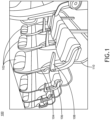
- FIG. 1 illustrates an aircraft cabin 100 including an aircraft seat 102, in accordance with one or more embodiments of the disclosure.
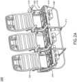
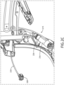
- FIGS. 2A-2E illustrate a seat frame 200 of the aircraft seat 102, in accordance with one or more embodiments of the disclosure.
- the aircraft seat 102 may include, but is not limited to, a business class or first-class passenger seat, an economy-class passenger seat, a crew member seat, or the like. It is noted the terms “aircraft seats” and “passenger seats” may be considered equivalent, for purposes of the disclosure.
- the aircraft seat 102 may be rotatable about an axis (e.g., swivelable).
- the aircraft seat 102 may be fully positionable between the outer limits of motion as defined by the moveable components of the aircraft seat 102.
- the aircraft seat 102 may be fully positionable between the outer limits of motion as defined by one or more passenger compartment monuments of the passenger compartment.
- an upright or raised position may be considered a taxi, takeoff, or landing (TTL) position during select stages of flight (though the upright or raised position is not limited to use during the select stages of flight as the TTL position, but also may be used at any point during the flight), for purposes of the present disclosure.
- TTL taxi, takeoff, or landing
- any position that does not meet the above-defined requirements of the TTL position may be considered a non-TTL position, for purposes of the present disclosure.
- the aircraft seat 102 may be actuatable (e.g., translatable and/or rotatable) from the TTL position to a non-TTL position, and/or vice versa.
- the aircraft seat 102 may be capable of a fully upright or raised position, and that the TTL position may have a more reclined seatback cushion and a more angled upward seat pan cushion as compared to the fully upright or raised position. Therefore, the above description should not be interpreted as a limitation on the present disclosure but merely an illustration.
- an aircraft seat 102 may be translatable (e.g., trackable or slidable).
- the aircraft seat 102 may be rotatable about an axis cross-wise through the aircraft seat 102 into a position including, but not limited to, the upright or raised position, one or more lounge or reclined positions, and a lie-flat or bed position.
- the aircraft seat 102 may transition directly between the upright or raised position and the lie-flat or bed position.
- the aircraft seat 102 may transition through one or more lounge or reclined positions between the upright or raised position and the lie-flat or bed position.
- the aircraft seat 102 may transition into one or more lounge or reclined positions in a motion separate from the transition between the upright or raised position and the lie-flat or bed position. Therefore, the above description should not be interpreted as a limitation on the scope of the disclosure but merely an illustration.
- the aircraft seat 102 may include a seatback 104.
- the aircraft seat 102 may include a seat pan 106.
- the aircraft seat 102 may include one or more arms 108.
- the aircraft seat 102 may be coupled to a base 110.
- the base 110 may be couplable to a floor of the aircraft cabin 100.
- the base assembly 110 may be couplable to the floor of the aircraft cabin 100 via one or more tracks (not shown), one or more track covers, and/or one or more floor fittings (or track fasteners).
- the seatback 104 may include a headrest.
- the headrest may be integrated within the seatback 104.
- the headrest may be a separate component coupled to (or inserted into) the seatback 104.
- the headrest may be movable relative to the seatback frame of the aircraft seat 102 (e.g., adjustable, removable, or the like
- the aircraft seat 102 may include a frame 200.
- the frame 200 may include a seatback frame 202 and a seat frame 204.
- the aircraft seat 102 may include a seat pan frame 206.
- the seat frame 204 may include one or more components 208 and/or one or more components 210.
- the one or more components 208, 210 may be configured to allow and/or assist the aircraft seat 102 to recline and/or return to an upright position.
- One or more of the seatback frame 202 and/or the seat pan frame 206 may be directly coupled, or indirectly coupled via one or more interconnecting components, to the one or more of the components 208, 210 of the seat frame 204.
- the base assembly 210 may include one or more legs 212.
- the base assembly may include one or more front legs and one or more rear legs.
- the one or more legs 212 may be couplable to one or more portions of the frame 200 of the aircraft seat 102.
- the one or more legs 212 may be couplable to one or more structural beams 214.
- the one or more legs 212 may be couplable to one or more spreaders 216 (e.g., front and/or rear openings).
- the one or more legs 212 may be configured to attach to the one or more structural beams 214 and/or one or more spreaders 216 and secure to the one or more tracks located in the floor of the aircraft cabin via the one or more fittings.
- the aircraft seat 102 may include a recline lockout device 300 configured to prevent the aircraft seat 102 from reclining when in the locked/deployed position. It is noted that the recline lockout device 300 may be adapted and mounted in any orientation to cater to various aircraft seat base designs and requirements.
- FIGS. 1-2E depict the aircraft cabin 100 including a row of aircraft seats 102 including the recline lockout device 300
- FIGS. 1-2E are provided merely for illustrative purposes and shall not be construed as limiting the scope of the present disclosure.
- the aircraft cabin 100 may include one or more individual aircraft seats 102 including the recline lockout device 300.
- FIGS. 3A-3E illustrate the recline lockout device 300, in accordance with one or more embodiments of the present disclosure.
- FIG. 3A depicts a perspective view of the recline lockout device 300, in accordance with one or more embodiments of the present disclosure.
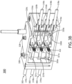
- FIG. 3B depicts a perspective cross-sectional view of the recline lockout device 300 in the unlocked position, in accordance with one or more embodiments of the present disclosure.
- FIG. 3C depicts a perspective cross-sectional view of the recline lockout device 300 in the locked/deployed position, in accordance with one or more embodiments of the present disclosure.
- FIG. 3A depicts a perspective view of the recline lockout device 300, in accordance with one or more embodiments of the present disclosure.
- FIG. 3B depicts a perspective cross-sectional view of the recline lockout device 300 in the unlocked position, in accordance with one or more embodiments of the present disclosure.
- FIG. 3C depicts a perspective cross-sectional view of the rec
- FIG. 3D depicts a cross-sectional view of the recline lockout device 300 in the locked position, in accordance with one or more embodiments of the present disclosure.
- FIG. 3E depicts a cross-sectional view of the recline lockout device 300 in the locked position, in accordance with one or more embodiments of the present disclosure.
- the recline lockout device 300 may include one or more modular lockout assemblies 302.
- the device 300 may include a first modular lockout assembly 302 (e.g., a bottom lockout assembly 302), a second modular lockout assembly 302 (e.g., a middle lockout assembly 302), and a third modular lockout assembly 302 (e.g., a top lockout assembly 302).
- each modular lockout assembly 302 may be coupled to a respective aircraft seat 102, such that the first lockout assembly 302 corresponds to a first aircraft seat 102, the second lockout assembly 302 corresponds to a second aircraft seat 102, and the third lockout assembly 302 corresponds to a third aircraft seat 102.
- the lockout device 300 may include any number and/or configuration of modular lockout assemblies 302 suitable for coupling to any number and/or configuration of aircraft seats 102.
- the one or more modular lockout assemblies 302 may be stackable.
- the second modular lockout assembly 302 e.g., middle lockout assembly 302
- the third modular lockout assembly 302 e.g., top lockout assembly 302
- the modular lockout assemblies 302 may be adaptable based on the number of seats and/or the space constraints onboard the aircraft.
- the top plate assembly 304 may include a top plate 306 coupled to the one or more modular lockout assemblies 302.
- the top plate 306 may include one or more raised portions 308.
- the top plate assembly 304 may include one or more lockout cable openings 310 configured to receive one or more lockout cables 312.
- the raised portion 308 of the top plate 306 may include one or more lockout cable openings 310.
- the one or more lockout cables 312 may be coupled to an actuator assembly 215 via a lockout cable assembly 218.
- the lockout cable assembly 218 may include, but is not limited to, one or more adjusters 220, one or more disconnects 222, and one or more compensators 224.
- the actuator assembly 215 may include one or more actuators 226 coupled to one or more user control devices 228 via one or more actuating cables 230.
- the one or more actuators 226 may include any type of actuator known in the art including, but not limited to, one or more gas springs, one or more hydraulic spring actuators, or the like.
- the one or more user control devices 228 may be positioned within the armrest of the aircraft seat 102.
- the one or more user control devices 228 may include any user control device including, but not limited to, one or more buttons, one or more levers, one or more knobs, or the like.
- the one or more disconnects 222 may be configured to couple to the one or more actuating cables 230 coupled to the actuator 226 to the lockout device 300.
- the one or more disconnects 222 may couple to a first set of actuating cables 230a coupled to the actuator 226 and a second set of actuating cables 230b coupled to the lockout device 300.
- the one or more adjusters 220 may be configured to adjust a length of the one or more actuating cables 230 coupled to the one or more disconnects 222.
- the one or more compensators 224 may be configured to adjust a length of the one or more actuating cables 230 coupled to the one or more disconnects 222.
- the one or more compensators 224 may remove any slack in the one or more actuating cables 230 to allow for overtravel of the actuator 226 without stretching the one or more actuating cables.
- the lockout cable assembly 218 may be configured to integrate the lockout device 300 with the actuator assembly 216 of the aircraft seat 102, such that the lockout device 300 may "disengage" the one or more actuating cables 230 from reclining the aircraft seat 102.
- the aircraft seat 102 may include one or more lockout mechanisms 232 coupled to a portion of the seat frame 200.
- the one or more lockout mechanisms 232 may include, but are not limited to, one or more levers, one or more buttons, one or more knobs, one or more switches, or the like.
- the one or more lockout mechanisms 232 may be arranged proximate to the aircraft seat 102 (or rows of aircraft seats 102).
- the lockout lever 232 may be coupled to the seat pan frame 204.
- the lockout lever 232 may be hidden from passengers, while still being accessible to crew members when the passenger is occupying the respective aircraft seat (or rows of aircraft seats).
- the lockout lever 232 may be coupled to the lockout cable assembly 218 to "disconnect" (or lockout) the one or more actuating cables 230 to prevent the aircraft seat 102 from reclining.
- the lever 232 may disengage the one or more actuating cables 230 coupled to the actuator 226, such that the actuator 226 is not able to recline the seat.
- a crew member may disengage the reclining feature of the seat to prevent the passenger from individually reclining the seat 102 via the user control button 228, as will be discussed further herein.
- FIGS. 4-5B illustrate a modular lockout assembly 302 of the recline lockout device 300, in accordance with one or more embodiments of the present disclosure.
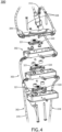
- FIG. 4 depicts an exploded view of the modular lockout assembly 302 of the recline lockout device 300, in accordance with one or more embodiments of the present disclosure.
- FIG. 5A depicts a cross-sectional view of the modular lockout assembly 302 of the recline lockout device 300 in the unlocked position, in accordance with one or more embodiments of the present disclosure.
- FIG. 5B depicts a cross-sectional view of the modular lockout assembly 302 of the recline lockout device 300 in the unlocked position where the levers do not interact out of plane, in accordance with one or more embodiments of the present disclosure.
- each modular lockout assembly 302 may include a housing 314.
- One or more sidewalls of the housing 314 may define a cavity 315.
- the housing 314 may include one or more cable openings 316 configured to receive one or more input cables 318 and one or more output cables 319.
- the housing 314 may include a first input cable opening 316a configured to receive a first input cable 318a, a second input cable opening 316b configured to receive a second input cable 318b, and a third input cable opening 316c configured to receive a third input cable 318c.
- the housing 314 may include a first output cable opening configured to receive a first output cable 319a, a second output cable opening configured to receive a second output cable 319b, and a third output cable opening configured to receive a third output cable 319c.
- first input/output cables 318a, 319a may coupled to the seat recline mechanism of the first aircraft seat
- the second input/output cables 318b, 319b may be coupled to the seat recline mechanism of the second aircraft seat
- third input/output cables 318c, 319c may be coupled to the seat recline mechanism of the third aircraft seat, as shown in FIGS. 3A-3B .
- the lockout mechanism 232 may be configured to pulls on the lockout cable 312.
- the one or more input levers 320 e.g., input levers 320a-c
- the output levers 321 are only able to rotate about the shaft and the one or more input levers 320 are able to translate vertical along the shaft and rotate about that shaft.
- Each modular lockout assembly 302 may include one or more spacers 326 spaced between the one or more levers 320.
- the one or more spacers 326 may be arranged along a shaft 328 positioned along the vertical axis of the lockout device 300.
- the one or more levers 320 may pivot about the shaft 328 positioned along the vertical axis of the lockout device 300.
- each modular lockout assembly 302 may further include one or more bearings positioned between the shaft 328 and the one or more levers 320, 321.
- the cavity 315 of the housing 314 may include one or more stopping surfaces 330.
- the one or more stopping surfaces 330 may act as a stopper to prevent the one or more levers 320, 321 from pivoting beyond a specified point.
- a crew member e.g., flight attendant, pilot, maintenance member, etc.
- the lockout cable 312 may translate to cause the input levers 320a-c to translate (as shown in FIG. 3C ), such that the respective levers do not interact with the output cables 321a-c (as shown in FIG. 3D-3E ), or vice versa.
- the cables 318, 319 are "locked out" to prevent the aircraft seat 102 from reclining via the actuator 226, such that a passenger is not able to individually recline their respective aircraft seat 102 (via the user button 228).
- the lockout mechanism 232 when the lockout mechanism 232 is actuated, it pulls on the lockout cable 312. When the lockout cable 312 is pulled, it in turn pulls on the input lever 320a to move the respective levers 320a, 320b, such that the lever 320b is positioned above the lever 321b and out of plane with the output lever 321.
- the output levers 321a, 321b are only able to rotate about the shaft 328 where the input levers 320a and levers 320b are able to translate vertical along the shaft 328 and rotate about that shaft 328. When the levers are out of plane, they are no longer able to interact with each other which effectively "locks out” the system.
Landscapes
- Engineering & Computer Science (AREA)
- General Engineering & Computer Science (AREA)
- Aviation & Aerospace Engineering (AREA)
- Health & Medical Sciences (AREA)
- Oral & Maxillofacial Surgery (AREA)
- Mechanical Engineering (AREA)
- Seats For Vehicles (AREA)
Abstract
Description
- Often it is desirable to have an aircraft seat configured with one or more comfort features for a passenger to adjust as necessary. For example, aircraft seats are often configured with recline mechanism to allow passengers to recline during flight. However, guidelines and/or standards require that the aircraft seat to be configured in a taxi, takeoff, or landing (TTL) position during select stages of flight.
- A recline lockout device for one or more aircraft seats is disclosed, in accordance with one or more embodiments of the present disclosure. The device includes one or more modular lockout assemblies. Each modular lockout assembly includes a housing including one or more sidewalls that define a cavity, the housing including one or more cable openings configured to receive one or more recline cables. Each modular lockout assembly includes one or more levers housed at least partially within the cavity of the housing, the one or more levers including at least a first lever coupled to a first recline cable of the one or more recline cables and a second lever coupled to a second recline cable of the one or more recline cables. Each modular lockout assembly includes one or more shafts, the one or more shafts including at least a first shaft and a second shaft, the first lever of the one or more levers configured to receive a portion of the first shaft and the second lever of the one or more levers configured to receive a portion of the second shaft, wherein the first lever is configured to pivot about an axis of the first shaft and the second lever is configured to pivot about an axis of the second shaft. The device includes one or more lockout cables coupled to one or more actuator assemblies of the one or more aircraft seats and at least one lever of the one or more levers, each actuator assembly configured to position the one or more aircraft seats between one of an upright position and a reclined position. The device includes one or more lockout control mechanisms configured to cause the one or more lockout cables to translate along an axis of the recline lockout device. Upon translating the one or more lockout cables along the axis, at least one of the first lever or the second lever is configured to translate along the axis to cause the first lever to disengage from the second lever. Upon disengaging the first lever from the second lever, the first recline lever is configured to disengage from the second recline cable to prevent the one or more actuator assemblies from actuating between the upright position and the reclined position.
- In some embodiments, each modular lockout assembly may further include one or more latch springs configured to couple the one or more levers to a sidewall of the one or more sidewalls of the housing.
- In some embodiments the device may further include a top plate including one or more lockout cable openings configured to receive the one or more lockout cables, the top plate configured to couple to the housing of at least one modular lockout assembly of the one or more modular lockout assemblies.
- In some embodiments, the one or more shafts include one or more bearings.
- In some embodiments the device may further include one or more lockout cable assemblies, each lockout cable assembly comprising at least one of one or more adjusters, one or more disconnects, or one or more compensators.
- In some embodiments, the one or more sidewalls of the housing may include one or more stopper surfaces configured to prevent the one or more levers from pivoting a predetermined threshold.
- In some embodiments, the one or more lockout control mechanisms may include one or more lockout levers coupled to a seat pan frame of the aircraft seat.
- In some embodiments, the recline lockout device may be coupled to a seat frame of the one or more aircraft seats.
- In some embodiments, the one or more modular assemblies may include a first modular assembly corresponding to a first aircraft seat within a row of aircraft seats; and one or more additional modular assemblies, each additional modular assembly corresponding to a respective aircraft seat within the row of aircraft seats, wherein the one or more additional modular assemblies are configured to be stacked on the first modular assembly.
- A row of aircraft seats is disclosed, in accordance with one or more embodiments of the present disclosure. The row of aircraft seats includes a seat frame. The row of aircraft seats includes one or more actuator assemblies, each actuator assembly including an actuator and one or more actuating cables, the actuator configured to position the one or more aircraft seats between one of an upright position and a reclined position, each actuator assembly further including one or more passenger recline mechanisms configured to cause the actuator to position the one or more aircraft seats between one of the upright position and the recline position. The row of aircraft seats includes a recline lockout device coupled to the seat frame. The device includes one or more modular lockout assemblies. Each modular lockout assembly includes a housing including one or more sidewalls that define a cavity, the housing including one or more cable openings configured to receive one or more recline cables. Each modular lockout assembly includes one or more levers housed at least partially within the cavity of the housing, the one or more levers including at least a first lever coupled to a first recline cable of the one or more recline cables and a second lever coupled to a second recline cable of the one or more recline cables. Each modular lockout assembly includes one or more shafts, the one or more shafts including at least a first shaft and a second shaft, the first lever of the one or more levers configured to receive a portion of the first shaft and the second lever of the one or more levers configured to receive a portion of the second shaft, wherein the first lever is configured to pivot about an axis of the first shaft and the second lever is configured to pivot about an axis of the second shaft. The device includes one or more lockout cables coupled to one or more actuator assemblies of the one or more aircraft seats and at least one lever of the one or more levers, each actuator assembly configured to position the one or more aircraft seats between one of an upright position and a reclined position. The device includes one or more lockout control mechanisms configured to cause the one or more lockout cables to translate along an axis of the recline lockout device. Upon translating the one or more lockout cables along the axis, at least one of the first lever or the second lever is configured to translate along the axis to cause the first lever to disengage from the second lever. Upon disengaging the first lever from the second lever, the first recline lever is configured to disengage from the second recline cable to prevent the one or more actuator assemblies from actuating between the upright position and the reclined position.
- In some embodiments, each modular lockout assembly may further include one or more latch springs configured to couple the one or more levers to a sidewall of the one or more sidewalls of the housing.
- In some embodiments, the one or more shafts include one or more bearings.
- In some embodiments the device may further include one or more lockout cable assemblies, each lockout cable assembly comprising at least one of one or more adjusters, one or more disconnects, or one or more compensators.
- In some embodiments, the recline lockout device may be coupled to a seat frame of the one or more aircraft seats.
- In some embodiments, the one or more modular assemblies may include a first modular assembly corresponding to a first aircraft seat within a row of aircraft seats; and one or more additional modular assemblies, each additional modular assembly corresponding to a respective aircraft seat within the row of aircraft seats, wherein the one or more additional modular assemblies are configured to be stacked on the first modular assembly.
- This Summary is provided solely as an introduction to subject matter that is fully described in the Detailed Description and Drawings. The Summary should not be considered to describe essential features nor be used to determine the scope of the Claims. Moreover, it is to be understood that both the foregoing Summary and the following Detailed Description are examples and explanatory only and are not necessarily restrictive of the subject matter claimed.
- The detailed description is described with reference to the accompanying figures. The use of the same reference numbers in different instances in the description and the figures may indicate similar or identical items. Various embodiments or examples ("examples") of the present disclosure are disclosed in the following detailed description and the accompanying drawings. The drawings are not necessarily to scale. In general, operations of disclosed processes may be performed in an arbitrary order, unless otherwise provided in the claims. In the drawings:
-
FIG. 1 is a simplified schematic view of an aircraft cabin with an aircraft seat including a recline lockout device, in accordance with one or more embodiments of the disclosure. -
FIG. 2A is a perspective view of a seat frame and a base assembly of the aircraft seat including the recline lockout device, in accordance with one or more embodiments of the disclosure. -
FIG. 2B is a perspective view of a seat frame and a base assembly of the aircraft seat including the recline lockout device, in accordance with one or more embodiments of the disclosure. -
FIG. 2C is an isolated view of the seat frame of the aircraft seat including the recline lockout device, in accordance with one or more embodiments of the disclosure. -
FIG. 2D is an isolated view of the seat frame of the aircraft seat including the recline lockout device, in accordance with one or more embodiments of the disclosure. -
FIG. 2E is an isolated view of the seat frame of the aircraft seat including the recline lockout device, in accordance with one or more embodiments of the disclosure. -
FIG. 3A is a perspective view of the recline lockout device, in accordance with one or more embodiments of the disclosure. -
FIG. 3B is a perspective cross-sectional view of the recline lockout device in the unlocked position, in accordance with one or more embodiments of the disclosure. -
FIG. 3C is a perspective cross-sectional view of the recline lockout device in the locked position, in accordance with one or more embodiments of the disclosure. -
FIG. 3D is a cross-sectional view of the recline lockout device in the locked position, in accordance with one or more embodiments of the disclosure. -
FIG. 3E is a cross-sectional view of the recline lockout device in the locked position, in accordance with one or more embodiments of the disclosure. -
FIG. 4 is an exploded view of the recline lockout device, in accordance with one or more embodiments of the disclosure. -
FIG. 5A is a cross-sectional view of the recline lockout device in the unlocked position, in accordance with one or more embodiments of the disclosure. -
FIG. 5B is a cross-sectional view of the recline lockout device in the unlocked position, in accordance with one or more embodiments of the disclosure. - Reference will now be made in detail to the subject matter disclosed, which is illustrated in the accompanying drawings.
- Before explaining one or more embodiments of the disclosure in detail, it is to be understood the embodiments are not limited in their application to the details of construction and the arrangement of the components or steps or methodologies set forth in the following description or illustrated in the drawings. In the following detailed description of embodiments, numerous specific details may be set forth in order to provide a more thorough understanding of the disclosure. However, it will be apparent to one of ordinary skill in the art having the benefit of the instant disclosure the embodiments disclosed herein may be practiced without some of these specific details. In other instances, well-known features may not be described in detail to avoid unnecessarily complicating the instant disclosure.
- As used herein a letter following a reference numeral is intended to reference an embodiment of the feature or element that may be similar, but not necessarily identical, to a previously described element or feature bearing the same reference numeral (e.g., 1, 1a, 1b). Such shorthand notations are used for purposes of convenience only and should not be construed to limit the disclosure in any way unless expressly stated to the contrary.
- Further, unless expressly stated to the contrary, "or" refers to an inclusive or and not to an exclusive or. For example, a condition A or B is satisfied by any one of the following: A is true (or present) and B is false (or not present), A is false (or not present) and B is true (or present), and both A and B are true (or present).
- In addition, use of "a" or "an" may be employed to describe elements and components of embodiments disclosed herein. This is done merely for convenience and "a" and "an" are intended to include "one," "one or more," or "at least one," and the singular also includes the plural unless it is obvious that it is meant otherwise.
- Finally, as used herein any reference to "one embodiment" or "some embodiments" means that a particular element, feature, structure, or characteristic described in connection with the embodiment is included in at least one embodiment disclosed herein. The appearances of the phrase "in some embodiments" in various places in the specification are not necessarily all referring to the same embodiment, and embodiments may include one or more of the features expressly described or inherently present herein, or any combination of or sub-combination of two or more such features, along with any other features which may not necessarily be expressly described or inherently present in the instant disclosure.
-
FIGS. 1-5B in general illustrate a recline lockout device for an aircraft seat, in accordance with one or more embodiments of the disclosure. - Often it is desirable to have an aircraft seat configured with one or more comfort features for a passenger to adjust as necessary. For example, aircraft seats are often configured with recline mechanism to allow passengers to recline during flight. However, guidelines and/or standards require that the aircraft seat to be configured in a taxi, takeoff, or landing (TTL) position during select stages of flight. It is noted an upright or raised position may be considered the TTL position during select stages of flight (though the upright or raised position is not limited to use during the select stages of flight as the TTL position, but also may be used at any point during the flight), for purposes of the present disclosure. In addition, it is noted that any position that does not meet the above-defined requirements of the TTL position may be considered a non-TTL position, for purposes of the present disclosure. Therefore, the above description should not be interpreted as a limitation on the present disclosure but merely an illustration.
- As such, there is a need for a recline lockout device for aircraft seats, which cures one or more of the shortfalls of previous approaches identified above. The lockout device should allow for passenger to individually recline their respective seats during select stages of flight when the lockout device is in the "unlocked" position. The lockout device should prevent passengers from individually reclining their respective seats during select stages of flight when the lockout device in the "locked" position. For example, a crew member may switch the lockout device to the "locked" position during select stages of flight (i.e. when the aircraft seat must be in the TTL position) to prevent the passengers from individually reclining their respective seats, in accordance with aviation guidelines and/or standards. In this regard, the crew member may lockout a row (or rows) of passenger aircraft seats using the lockout device.
- It is noted herein that the recline lockout device may be implemented in any environment or number of environments. For example, the environment may include any type of vehicle known in the art. For instance, the vehicle may be any air, land, or water-based personal equipment or vehicle; any air, land, or water-based commercial equipment or vehicle; any air, land, or water-based military equipment or vehicle known in the art. By way of another example, the environment may include a commercial or industrial establishment (e.g., a home or a business).
- Where the environment may be an aviation environment, the aircraft cabin designs need to be certified in accordance with aviation guidelines and standards, while being designed so as not to lose the intended functionality of the structures and/or monuments in the aircraft cabin. For example, the aircraft seats within the aircraft cabin may need to be configured in accordance with aviation guidelines and/or standards put forth by, but not limited to, the Federal Aviation Administration (FAA), the European Aviation Safety Agency (EASA) or any other flight certification agency or organization or any other guidelines agency or organization, or the like.
-
FIG. 1 illustrates anaircraft cabin 100 including anaircraft seat 102, in accordance with one or more embodiments of the disclosure.FIGS. 2A-2E illustrate aseat frame 200 of theaircraft seat 102, in accordance with one or more embodiments of the disclosure. - The
aircraft seat 102 may include, but is not limited to, a business class or first-class passenger seat, an economy-class passenger seat, a crew member seat, or the like. It is noted the terms "aircraft seats" and "passenger seats" may be considered equivalent, for purposes of the disclosure. - The
aircraft seat 102 may be rotatable about an axis (e.g., swivelable). Theaircraft seat 102 may be fully positionable between the outer limits of motion as defined by the moveable components of theaircraft seat 102. Where theaircraft seat 102 is installed within a passenger compartment, theaircraft seat 102 may be fully positionable between the outer limits of motion as defined by one or more passenger compartment monuments of the passenger compartment. It is noted an upright or raised position may be considered a taxi, takeoff, or landing (TTL) position during select stages of flight (though the upright or raised position is not limited to use during the select stages of flight as the TTL position, but also may be used at any point during the flight), for purposes of the present disclosure. In addition, it is noted that any position that does not meet the above-defined requirements of the TTL position may be considered a non-TTL position, for purposes of the present disclosure. Further, it is noted theaircraft seat 102 may be actuatable (e.g., translatable and/or rotatable) from the TTL position to a non-TTL position, and/or vice versa. Further, it is noted theaircraft seat 102 may be capable of a fully upright or raised position, and that the TTL position may have a more reclined seatback cushion and a more angled upward seat pan cushion as compared to the fully upright or raised position. Therefore, the above description should not be interpreted as a limitation on the present disclosure but merely an illustration. - In general, an
aircraft seat 102 may be translatable (e.g., trackable or slidable). Theaircraft seat 102 may be rotatable about an axis cross-wise through theaircraft seat 102 into a position including, but not limited to, the upright or raised position, one or more lounge or reclined positions, and a lie-flat or bed position. For example, theaircraft seat 102 may transition directly between the upright or raised position and the lie-flat or bed position. By way of another example, it is noted theaircraft seat 102 may transition through one or more lounge or reclined positions between the upright or raised position and the lie-flat or bed position. By way of another example, theaircraft seat 102 may transition into one or more lounge or reclined positions in a motion separate from the transition between the upright or raised position and the lie-flat or bed position. Therefore, the above description should not be interpreted as a limitation on the scope of the disclosure but merely an illustration. - The
aircraft seat 102 may include aseatback 104. Theaircraft seat 102 may include aseat pan 106. Theaircraft seat 102 may include one ormore arms 108. Theaircraft seat 102 may be coupled to abase 110. The base 110 may be couplable to a floor of theaircraft cabin 100. For example, thebase assembly 110 may be couplable to the floor of theaircraft cabin 100 via one or more tracks (not shown), one or more track covers, and/or one or more floor fittings (or track fasteners). - The
seatback 104 may include a headrest. For example, the headrest may be integrated within theseatback 104. By way of another example, the headrest may be a separate component coupled to (or inserted into) theseatback 104. For instance, the headrest may be movable relative to the seatback frame of the aircraft seat 102 (e.g., adjustable, removable, or the like - The
aircraft seat 102 may include aframe 200. Theframe 200 may include aseatback frame 202 and aseat frame 204. Theaircraft seat 102 may include aseat pan frame 206. Theseat frame 204 may include one ormore components 208 and/or one ormore components 210. For example, the one ormore components aircraft seat 102 to recline and/or return to an upright position. - One or more of the
seatback frame 202 and/or theseat pan frame 206 may be directly coupled, or indirectly coupled via one or more interconnecting components, to the one or more of thecomponents seat frame 204. - The
base assembly 210 may include one ormore legs 212. For example, the base assembly may include one or more front legs and one or more rear legs. The one ormore legs 212 may be couplable to one or more portions of theframe 200 of theaircraft seat 102. For example, the one ormore legs 212 may be couplable to one or morestructural beams 214. By way of another example, the one ormore legs 212 may be couplable to one or more spreaders 216 (e.g., front and/or rear openings). In this regard, the one ormore legs 212 may be configured to attach to the one or morestructural beams 214 and/or one ormore spreaders 216 and secure to the one or more tracks located in the floor of the aircraft cabin via the one or more fittings. - The
aircraft seat 102 may include arecline lockout device 300 configured to prevent theaircraft seat 102 from reclining when in the locked/deployed position. It is noted that therecline lockout device 300 may be adapted and mounted in any orientation to cater to various aircraft seat base designs and requirements. - Although
FIGS. 1-2E depict theaircraft cabin 100 including a row ofaircraft seats 102 including therecline lockout device 300, it is noted thatFIGS. 1-2E are provided merely for illustrative purposes and shall not be construed as limiting the scope of the present disclosure. For example, theaircraft cabin 100 may include one or moreindividual aircraft seats 102 including therecline lockout device 300. -
FIGS. 3A-3E illustrate therecline lockout device 300, in accordance with one or more embodiments of the present disclosure. In particular,FIG. 3A depicts a perspective view of therecline lockout device 300, in accordance with one or more embodiments of the present disclosure. In particular,FIG. 3B depicts a perspective cross-sectional view of therecline lockout device 300 in the unlocked position, in accordance with one or more embodiments of the present disclosure. In particular,FIG. 3C depicts a perspective cross-sectional view of therecline lockout device 300 in the locked/deployed position, in accordance with one or more embodiments of the present disclosure. In particular,FIG. 3D depicts a cross-sectional view of therecline lockout device 300 in the locked position, in accordance with one or more embodiments of the present disclosure. In particular,FIG. 3E depicts a cross-sectional view of therecline lockout device 300 in the locked position, in accordance with one or more embodiments of the present disclosure. - The
recline lockout device 300 may include one or moremodular lockout assemblies 302. For example, as shown inFIGS. 3A-3E , thedevice 300 may include a first modular lockout assembly 302 (e.g., a bottom lockout assembly 302), a second modular lockout assembly 302 (e.g., a middle lockout assembly 302), and a third modular lockout assembly 302 (e.g., a top lockout assembly 302). In this regard, eachmodular lockout assembly 302 may be coupled to arespective aircraft seat 102, such that thefirst lockout assembly 302 corresponds to afirst aircraft seat 102, thesecond lockout assembly 302 corresponds to asecond aircraft seat 102, and thethird lockout assembly 302 corresponds to athird aircraft seat 102. It is noted that thelockout device 300 may include any number and/or configuration ofmodular lockout assemblies 302 suitable for coupling to any number and/or configuration of aircraft seats 102. - The one or more
modular lockout assemblies 302 may be stackable. For example, as shown inFIGS. 3A-3E , the second modular lockout assembly 302 (e.g., middle lockout assembly 302) may be stacked at least partially on top of the first modular lockout assembly 302 (e.g., bottom lockout assembly 302). By way of another example, the third modular lockout assembly 302 (e.g., top lockout assembly 302) may be stacked at least partially on top of the second modular lockout assembly 302 (e.g., middle lockout assembly 302). In this regard, themodular lockout assemblies 302 may be adaptable based on the number of seats and/or the space constraints onboard the aircraft. - The
recline lockout device 300 may include atop plate assembly 304. For example, therecline lockout device 300 may include atop plate assembly 304 coupled to the one or moremodular lockout assemblies 302. For instance, thetop plate assembly 304 may be coupled to one or moremodular lockout assemblies 302 via one or more fasteners 301 (e.g., screws, bolts, and the like). - The
top plate assembly 304 may include atop plate 306 coupled to the one or moremodular lockout assemblies 302. Thetop plate 306 may include one or more raisedportions 308. - The
top plate assembly 304 may include one or morelockout cable openings 310 configured to receive one ormore lockout cables 312. For example, the raisedportion 308 of thetop plate 306 may include one or morelockout cable openings 310. - The one or
more lockout cables 312 may include one or more conduit endfittings 313. - Referring to
FIGS. 2A-2E , the one ormore lockout cables 312 may be coupled to anactuator assembly 215 via alockout cable assembly 218. - Referring to
FIG. 2E , thelockout cable assembly 218 may include, but is not limited to, one ormore adjusters 220, one ormore disconnects 222, and one ormore compensators 224. - The
actuator assembly 215 may include one ormore actuators 226 coupled to one or moreuser control devices 228 via one ormore actuating cables 230. The one ormore actuators 226 may include any type of actuator known in the art including, but not limited to, one or more gas springs, one or more hydraulic spring actuators, or the like. - The one or more
user control devices 228 may be positioned within the armrest of theaircraft seat 102. The one or moreuser control devices 228 may include any user control device including, but not limited to, one or more buttons, one or more levers, one or more knobs, or the like. - The one or
more disconnects 222 may be configured to couple to the one ormore actuating cables 230 coupled to theactuator 226 to thelockout device 300. The one ormore disconnects 222 may couple to a first set ofactuating cables 230a coupled to theactuator 226 and a second set of actuatingcables 230b coupled to thelockout device 300. - For example, the one or
more adjusters 220 may be configured to adjust a length of the one ormore actuating cables 230 coupled to the one ormore disconnects 222. By way of another example, the one ormore compensators 224 may be configured to adjust a length of the one ormore actuating cables 230 coupled to the one ormore disconnects 222. For instance, the one ormore compensators 224 may remove any slack in the one ormore actuating cables 230 to allow for overtravel of theactuator 226 without stretching the one or more actuating cables. In this regard, thelockout cable assembly 218 may be configured to integrate thelockout device 300 with theactuator assembly 216 of theaircraft seat 102, such that thelockout device 300 may "disengage" the one ormore actuating cables 230 from reclining theaircraft seat 102. - The
aircraft seat 102 may include one ormore lockout mechanisms 232 coupled to a portion of theseat frame 200. The one ormore lockout mechanisms 232 may include, but are not limited to, one or more levers, one or more buttons, one or more knobs, one or more switches, or the like. - The one or
more lockout mechanisms 232 may be arranged proximate to the aircraft seat 102 (or rows of aircraft seats 102). For example, thelockout lever 232 may be coupled to theseat pan frame 204. In this regard, thelockout lever 232 may be hidden from passengers, while still being accessible to crew members when the passenger is occupying the respective aircraft seat (or rows of aircraft seats). - The
lockout lever 232 may be coupled to thelockout cable assembly 218 to "disconnect" (or lockout) the one ormore actuating cables 230 to prevent theaircraft seat 102 from reclining. For example, when engaged, thelever 232 may disengage the one ormore actuating cables 230 coupled to theactuator 226, such that theactuator 226 is not able to recline the seat. In this regard, a crew member may disengage the reclining feature of the seat to prevent the passenger from individually reclining theseat 102 via theuser control button 228, as will be discussed further herein. -
FIGS. 4-5B illustrate amodular lockout assembly 302 of therecline lockout device 300, in accordance with one or more embodiments of the present disclosure. In particular,FIG. 4 depicts an exploded view of themodular lockout assembly 302 of therecline lockout device 300, in accordance with one or more embodiments of the present disclosure. In particular,FIG. 5A depicts a cross-sectional view of themodular lockout assembly 302 of therecline lockout device 300 in the unlocked position, in accordance with one or more embodiments of the present disclosure. In particular,FIG. 5B depicts a cross-sectional view of themodular lockout assembly 302 of therecline lockout device 300 in the unlocked position where the levers do not interact out of plane, in accordance with one or more embodiments of the present disclosure. - Referring to
FIGS. 3A-5B , eachmodular lockout assembly 302 may include ahousing 314. One or more sidewalls of thehousing 314 may define acavity 315. - The
housing 314 may include one ormore cable openings 316 configured to receive one ormore input cables 318 and one ormore output cables 319. For example, thehousing 314 may include a firstinput cable opening 316a configured to receive afirst input cable 318a, a secondinput cable opening 316b configured to receive asecond input cable 318b, and a thirdinput cable opening 316c configured to receive athird input cable 318c. By way of another example, thehousing 314 may include a first output cable opening configured to receive afirst output cable 319a, a second output cable opening configured to receive asecond output cable 319b, and a third output cable opening configured to receive athird output cable 319c. For instance, the first input/output cables output cables output cables FIGS. 3A-3B . - Each
modular lockout assembly 302 may include one or more levers housed within thecavity 315 of thehousing 314. For example, eachmodular lockout assembly 302 may include one or more input levers 320 and one or more output levers 321. For instance, as shown inFIG. 3B , the first modular lockout assembly 302 (e.g., a bottom lockout assembly 302) may include afirst input lever 320a and afirst output lever 321a, the second modular lockout assembly 302 (e.g., a middle lockout assembly 302) may include asecond input lever 320b and asecond output lever 321b, and the third modular lockout assembly (e.g., a top lockout assembly 302) may include athird input lever 320c and athird output lever 321c. - When the
lockout mechanism 232 is actuated, as discussed further herein, thelockout mechanism 232 may be configured to pulls on thelockout cable 312. Upon pulling thelockout cable 312, the one or more input levers 320 (e.g., input levers 320a-c) may translate along theshaft 328 to move therespective levers 320b-c out of plane with the one or more output levers 321. In this regard, the output levers 321 are only able to rotate about the shaft and the one or more input levers 320 are able to translate vertical along the shaft and rotate about that shaft. When the levers are out of plane, they are no longer able to interact with each other which effectively "locks out" the system, such that when one lever is "disengaged" the respective lever does not interact with the additional lever and thus disables the passenger's ability to recline theaircraft seat 102 via theactuator 226, as shown inFIGS. 5A-5B . - Each
modular lockout assembly 302 may include one or more latch springs 322 coupling the one ormore levers 320 to a surface of thehousing 314 via one ormore fasteners 301. - Each
modular lockout assembly 302 may include one or more spacers 326 spaced between the one ormore levers 320. For example, the one or more spacers 326 may be arranged along ashaft 328 positioned along the vertical axis of thelockout device 300. In this regard, the one ormore levers 320 may pivot about theshaft 328 positioned along the vertical axis of thelockout device 300. - Although though not shown, each
modular lockout assembly 302 may further include one or more bearings positioned between theshaft 328 and the one ormore levers - Referring to
FIGS. 5A-5B , thecavity 315 of thehousing 314 may include one or more stopping surfaces 330. For example, the one or more stoppingsurfaces 330 may act as a stopper to prevent the one ormore levers - To disengage the recline feature, a crew member (e.g., flight attendant, pilot, maintenance member, etc.) may engage the
lever 232. Upon engaging thelever 232, thelockout cable 312 may translate to cause the input levers 320a-c to translate (as shown inFIG. 3C ), such that the respective levers do not interact with theoutput cables 321a-c (as shown inFIG. 3D-3E ), or vice versa. In this regard, thecables aircraft seat 102 from reclining via theactuator 226, such that a passenger is not able to individually recline their respective aircraft seat 102 (via the user button 228). - For example, when the
lockout mechanism 232 is actuated, it pulls on thelockout cable 312. When thelockout cable 312 is pulled, it in turn pulls on theinput lever 320a to move therespective levers lever 320b is positioned above thelever 321b and out of plane with theoutput lever 321. The output levers 321a, 321b are only able to rotate about theshaft 328 where the input levers 320a and levers 320b are able to translate vertical along theshaft 328 and rotate about thatshaft 328. When the levers are out of plane, they are no longer able to interact with each other which effectively "locks out" the system. - Although the disclosure has been described with reference to the embodiments illustrated in the attached drawing figures, variations are possible without departing from the scope of the invention defined by the claims.
Claims (15)
- A recline lockout device for one or more aircraft seats, the device comprising:one or more modular lockout assemblies (302), each modular lockout assembly comprising:a housing (314) including one or more sidewalls that define a cavity (315), the housing including one or more cable openings (316) configured to receive one or more recline cables;one or more levers (320, 321) housed at least partially within the cavity of the housing, the one or more levers including at least a first lever coupled to a first recline cable of the one or more recline cables and a second lever coupled to a second recline cable of the one or more recline cables; andone or more shafts (328), the one or more shafts including at least a first shaft and a second shaft, the first lever of the one or more levers configured to receive a portion of the first shaft and the second lever of the one or more levers configured to receive a portion of the second shaft, wherein the first lever is configured to pivot about an axis of the first shaft and the second lever is configured to pivot about an axis of the second shaft;one or more lockout cables (312) coupled to one or more actuator assemblies of the one or more aircraft seats and at least one lever of the one or more levers, each actuator assembly configured to position the one or more aircraft seats between one of an upright position and a reclined position; andone or more lockout control mechanisms configured to cause the one or more lockout cables to translate along an axis of the recline lockout device,upon translating the one or more lockout cables along the axis, at least one of the first lever or the second lever is configured to translate along the axis to cause the first lever to disengage from the second lever,upon disengaging the first lever from the second lever, the first recline lever is configured to disengage from the second recline cable to prevent the one or more actuator assemblies from actuating between the upright position and the reclined position.
- The device of Claim 1, wherein each modular lockout assembly further comprises:
one or more latch springs (322) configured to couple the one or more levers to a sidewall of the one or more sidewalls of the housing. - The device of Claim 1 or 2, further comprising:
a top plate (306), the top plate including one or more lockout cable openings (310) configured to receive the one or more lockout cables, the top plate configured to couple to the housing of at least one modular lockout assembly of the one or more modular lockout assemblies. - The device of any preceding Claim, wherein the one or more shafts include one or more bearings.
- The device of any preceding Claim, further comprising:
one or more lockout cable assemblies, each lockout cable assembly comprising at least one of one or more adjusters (220), one or more disconnects (222), or one or more compensators (224). - The device of any preceding Claim, wherein the one or more sidewalls of the housing including one or more stopper surfaces (330) configured to prevent the one or more levers from pivoting a predetermined threshold.
- The device of any preceding Claim, wherein the one or more lockout control mechanisms comprises:
one or more lockout levers coupled to a seat pan frame of the aircraft seat. - The device of any preceding Claim, wherein the recline lockout device is coupled to a seat frame (204) of the one or more aircraft seats.
- The device of any preceding Claim, wherein the one or more modular assemblies comprise:a first modular assembly corresponding to a first aircraft seat within a row of aircraft seats; andone or more additional modular assemblies, each additional modular assembly corresponding to a respective aircraft seat within the row of aircraft seats,wherein the one or more additional modular assemblies are configured to be stacked on the first modular assembly.
- A row of aircraft seats, the row of aircraft seats comprising:a seat frame (204);one or more actuator assemblies (216), each actuator assembly including an actuator (226) and one or more actuating cables (230), the actuator configured to position the one or more aircraft seats between one of an upright position and a reclined position, each actuator assembly further including one or more passenger recline mechanisms configured to cause the actuator to position the one or more aircraft seats between one of the upright position and the recline position; anda recline lockout device (300) coupled to the seat frame, the recline lockout device comprising:one or more modular lockout assemblies, each modular lockout assembly comprising:a housing (314) including one or more sidewalls that define a cavity (315), the housing including one or more cable openings (316) configured to receive one or more recline cables;one or more levers (320, 321) housed at least partially within the cavity of the housing, the one or more levers including at least a first lever coupled to a first recline cable of the one or more recline cables and a second lever coupled to a second recline cable of the one or more recline cables; andone or more shafts (328), the one or more shafts including at least a first shaft and a second shaft, the first lever of the one or more levers configured to receive a portion of the first shaft and the second lever of the one or more levers configured to receive a portion of the second shaft, wherein the first lever is configured to pivot about an axis of the first shaft and the second lever is configured to pivot about an axis of the second shaft;one or more lockout cables (312) coupled to the one or more actuator assemblies and at least one lever of the one or more levers; andone or more lockout control mechanisms configured to cause the one or more lockout cables to translate along an axis of the recline lockout device,upon translating the one or more lockout cables along the axis, at least one of the first lever or the second lever is configured to translate along the axis to cause the first lever to disengage from the second lever,upon disengaging the first lever from the second lever, the first recline lever is configured to disengage from the second recline cable to prevent the one or more actuator assemblies from actuating between the upright position and the reclined position.
- The row of aircraft seats of Claim 10, wherein each modular lockout assembly further comprises:
one or more latch springs (322) configured to couple the one or more levers to a sidewall of the one or more sidewalls of the housing. - The row of aircraft seats of Claim 10 or 11, wherein the one or more shafts include one or more bearings.
- The row of aircraft seats of Claim 10, 11 or 12, further comprising:
one or more lockout cable assemblies, each lockout cable assembly comprising at least one of one or more adjusters (220), one or more disconnects (222), or one or more compensators (224). - The row of aircraft seats of any of Claims 10 to 13, wherein the one or more lockout control mechanisms comprises:
one or more lockout levers coupled to a seat pan frame of the aircraft seat. - The row of aircraft seats of any of Claims 10 to 14, wherein the one or more modular assemblies comprise:a first modular assembly corresponding to a first aircraft seat within the row of aircraft seats; andone or more additional modular assemblies, each additional modular assembly corresponding to a respective aircraft seat within the row of aircraft seats,wherein the one or more additional modular assemblies are configured to be stacked on the first modular assembly.
Applications Claiming Priority (1)
| Application Number | Priority Date | Filing Date | Title |
|---|---|---|---|
| US18/229,823 US12522361B2 (en) | 2023-08-03 | 2023-08-03 | Recline lockout device for aircraft seat |
Publications (1)
| Publication Number | Publication Date |
|---|---|
| EP4501787A1 true EP4501787A1 (en) | 2025-02-05 |
Family
ID=92214413
Family Applications (1)
| Application Number | Title | Priority Date | Filing Date |
|---|---|---|---|
| EP24192971.0A Pending EP4501787A1 (en) | 2023-08-03 | 2024-08-05 | Recline lockout device for aircraft seat |
Country Status (2)
| Country | Link |
|---|---|
| US (1) | US12522361B2 (en) |
| EP (1) | EP4501787A1 (en) |
Citations (3)
| Publication number | Priority date | Publication date | Assignee | Title |
|---|---|---|---|---|
| US5758544A (en) * | 1996-04-10 | 1998-06-02 | P. L. Porter Co. | System and method for locking out an output device when an input device is actuated |
| US7182402B1 (en) * | 2004-06-22 | 2007-02-27 | Timco Aviation Services, Inc. | Seat recline control override |
| EP3744565A1 (en) * | 2015-02-20 | 2020-12-02 | Safran Seats USA LLC | Haptic system: recline activation control |
Family Cites Families (12)
| Publication number | Priority date | Publication date | Assignee | Title |
|---|---|---|---|---|
| JPH0286394A (en) * | 1988-09-22 | 1990-03-27 | Sanshin Ind Co Ltd | Remote controller |
| DE102004032880B4 (en) * | 2004-07-07 | 2007-09-06 | Recaro Aircraft Seating Gmbh & Co. Kg | Passenger seating |
| US7587956B2 (en) * | 2006-08-29 | 2009-09-15 | Franklin Products, Inc. | Device for controlling motion |
| DE202011005162U1 (en) * | 2011-04-12 | 2011-06-09 | AS Rollen GmbH, 42499 | Actuating device for the locking device at least one rotatably and / or pivotally mounted roller |
| US9981571B2 (en) | 2014-03-31 | 2018-05-29 | B/E Aerospace, Inc. | Electronically actuated mechanical cable release for locking gas spring and method |
| EP3371000B1 (en) | 2015-11-03 | 2020-09-16 | Safran Seats USA LLC | Pull actuator release for reclining seats |
| US10173778B2 (en) | 2016-05-17 | 2019-01-08 | Itt Manufacturing Enterprises Llc | Button assembly for seat position control |
| US10279917B1 (en) | 2018-03-28 | 2019-05-07 | B/E Aerospace, Inc. | Pivoting cable actuating mechanism |
| JP7051253B2 (en) | 2020-02-28 | 2022-04-11 | コイト電工株式会社 | Seating device |
| JP7527915B2 (en) * | 2020-09-24 | 2024-08-05 | 株式会社ハイレックスコーポレーション | Operating device |
| JP7361676B2 (en) | 2020-11-30 | 2023-10-16 | コイト電工株式会社 | seat equipment |
| WO2024242817A2 (en) * | 2023-05-23 | 2024-11-28 | Itt Manufacturing Enterprises Llc | Button assembly with a modular button and sleeve having an infinitely rotational cable exit |
-
2023
- 2023-08-03 US US18/229,823 patent/US12522361B2/en active Active
-
2024
- 2024-08-05 EP EP24192971.0A patent/EP4501787A1/en active Pending
Patent Citations (3)
| Publication number | Priority date | Publication date | Assignee | Title |
|---|---|---|---|---|
| US5758544A (en) * | 1996-04-10 | 1998-06-02 | P. L. Porter Co. | System and method for locking out an output device when an input device is actuated |
| US7182402B1 (en) * | 2004-06-22 | 2007-02-27 | Timco Aviation Services, Inc. | Seat recline control override |
| EP3744565A1 (en) * | 2015-02-20 | 2020-12-02 | Safran Seats USA LLC | Haptic system: recline activation control |
Also Published As
| Publication number | Publication date |
|---|---|
| US12522361B2 (en) | 2026-01-13 |
| US20250042551A1 (en) | 2025-02-06 |
Similar Documents
| Publication | Publication Date | Title |
|---|---|---|
| EP3453620A1 (en) | Tracking base assembly for aircraft seat | |
| US11299274B1 (en) | Aircraft passenger compartment with an accessibility door | |
| US12240606B2 (en) | Monitor stop device | |
| EP3812275B1 (en) | Adjustable ottoman | |
| EP4108566B1 (en) | Carriage assembly with overload protection | |
| US12187437B2 (en) | Economy class passenger seat with bed mode and removable cushion | |
| EP4079636B1 (en) | Vertical adjustment mechanism for an aircraft seat | |
| EP4079639B1 (en) | Deployable cabin attendant seat system | |
| US12522361B2 (en) | Recline lockout device for aircraft seat | |
| US11472559B1 (en) | Coil hinge for aircraft seat | |
| US5758544A (en) | System and method for locking out an output device when an input device is actuated | |
| CN113525691B (en) | Aircraft seat with spring assisted actuation | |
| EP4509406A1 (en) | Deployable armrest for an aircraft seat | |
| US11377215B1 (en) | Stowable flight attendant seat system | |
| US12630290B2 (en) | Deployable armrest for an aircraft seat | |
| US20250058880A1 (en) | Deployable armrest for an aircraft seat | |
| US11572001B1 (en) | Quick release headrest removal assembly | |
| EP3647195B1 (en) | Aisle access side facing seat | |
| EP4549320A1 (en) | Transformable cabin attendant aircraft seat | |
| EP4015385B1 (en) | Aircraft passenger seat row with cabin attendant seat | |
| EP4286277A1 (en) | Economy class passenger seat row with bed mode | |
| EP4506251A1 (en) | Seat extension furniture for aircraft seats | |
| EP4223642A1 (en) | Passenger seating assembly with swinging seatpan for increased passenger egress space | |
| EP4600153A1 (en) | Passenger seat with decoupling motion mechanism for reduced mobility seating | |
| US20250136283A1 (en) | Transformable cabin attendant aircraft seat |
Legal Events
| Date | Code | Title | Description |
|---|---|---|---|
| PUAI | Public reference made under article 153(3) epc to a published international application that has entered the european phase |
Free format text: ORIGINAL CODE: 0009012 |
|
| STAA | Information on the status of an ep patent application or granted ep patent |
Free format text: STATUS: THE APPLICATION HAS BEEN PUBLISHED |
|
| AK | Designated contracting states |
Kind code of ref document: A1 Designated state(s): AL AT BE BG CH CY CZ DE DK EE ES FI FR GB GR HR HU IE IS IT LI LT LU LV MC ME MK MT NL NO PL PT RO RS SE SI SK SM TR |
|
| STAA | Information on the status of an ep patent application or granted ep patent |
Free format text: STATUS: REQUEST FOR EXAMINATION WAS MADE |
|
| 17P | Request for examination filed |
Effective date: 20250805 |
|
| GRAP | Despatch of communication of intention to grant a patent |
Free format text: ORIGINAL CODE: EPIDOSNIGR1 |
|
| STAA | Information on the status of an ep patent application or granted ep patent |
Free format text: STATUS: GRANT OF PATENT IS INTENDED |
|
| INTG | Intention to grant announced |
Effective date: 20260224 |