EP4501774A1 - Véhicule sous-marin pour espaces étanches - Google Patents
Véhicule sous-marin pour espaces étanches Download PDFInfo
- Publication number
- EP4501774A1 EP4501774A1 EP23189601.0A EP23189601A EP4501774A1 EP 4501774 A1 EP4501774 A1 EP 4501774A1 EP 23189601 A EP23189601 A EP 23189601A EP 4501774 A1 EP4501774 A1 EP 4501774A1
- Authority
- EP
- European Patent Office
- Prior art keywords
- underwater vehicle
- previous
- vehicle according
- ring
- underwater
- Prior art date
- Legal status (The legal status is an assumption and is not a legal conclusion. Google has not performed a legal analysis and makes no representation as to the accuracy of the status listed.)
- Withdrawn
Links
Images



Classifications
-
- B—PERFORMING OPERATIONS; TRANSPORTING
- B63—SHIPS OR OTHER WATERBORNE VESSELS; RELATED EQUIPMENT
- B63G—OFFENSIVE OR DEFENSIVE ARRANGEMENTS ON VESSELS; MINE-LAYING; MINE-SWEEPING; SUBMARINES; AIRCRAFT CARRIERS
- B63G8/00—Underwater vessels, e.g. submarines; Equipment specially adapted therefor
- B63G8/14—Control of attitude or depth
- B63G8/16—Control of attitude or depth by direct use of propellers or jets
-
- B—PERFORMING OPERATIONS; TRANSPORTING
- B63—SHIPS OR OTHER WATERBORNE VESSELS; RELATED EQUIPMENT
- B63G—OFFENSIVE OR DEFENSIVE ARRANGEMENTS ON VESSELS; MINE-LAYING; MINE-SWEEPING; SUBMARINES; AIRCRAFT CARRIERS
- B63G8/00—Underwater vessels, e.g. submarines; Equipment specially adapted therefor
- B63G8/001—Underwater vessels adapted for special purposes, e.g. unmanned underwater vessels; Equipment specially adapted therefor, e.g. docking stations
-
- B—PERFORMING OPERATIONS; TRANSPORTING
- B63—SHIPS OR OTHER WATERBORNE VESSELS; RELATED EQUIPMENT
- B63G—OFFENSIVE OR DEFENSIVE ARRANGEMENTS ON VESSELS; MINE-LAYING; MINE-SWEEPING; SUBMARINES; AIRCRAFT CARRIERS
- B63G8/00—Underwater vessels, e.g. submarines; Equipment specially adapted therefor
- B63G8/001—Underwater vessels adapted for special purposes, e.g. unmanned underwater vessels; Equipment specially adapted therefor, e.g. docking stations
- B63G2008/002—Underwater vessels adapted for special purposes, e.g. unmanned underwater vessels; Equipment specially adapted therefor, e.g. docking stations unmanned
- B63G2008/004—Underwater vessels adapted for special purposes, e.g. unmanned underwater vessels; Equipment specially adapted therefor, e.g. docking stations unmanned autonomously operating
Definitions
- the present disclosure relates to an underwater vehicle for 3D mapping of underwater confined environments. More particularly, relates to an autonomous underwater vehicle for exploring and mapping tight-spaces such as underwater tunnels, caves, wells, among others.
- a ⁇ AUV (micro autonomous underwater vehicle) of 0.075m radius and 6 propellers around the hull was developed by S. A. Watson, D. J. P. Crutchley and P. N. Green, " The design and technical challenges of a micro-autonomous underwater vehicle ( ⁇ AUV) ", Proc. IEEE Int. Conf. Mechatronics Automat., pp. 567-572, Aug. 2011 . and S. A. Watson and P. N. Green, " Design considerations for micro-autonomous underwater vehicles ( ⁇ AUVs) ", Proc. IEEE Conf. Robot. Automat. Mechatronics, pp. 429-434, Dec. 2010 ] for monitoring nuclear storage ponds.
- a key disadvantage of these AUV designs is the presence of external propulsion systems, which could become entangled with objects such as ropes or cables encountered during operation.
- Lopes et al UNEXMIN A new concept to sustainably obtain geological information from flooded mine, European Geologist Journal, issue 44 pg 54-57 presented a AUV for exploration of confined underwater spaces with an almost spherical shape with a set of 8 thrusters distributed in two lateral cross shaped thruster manifolds.
- US2021089031 discloses an autonomous underwater vehicle (AUV) that includes a frame and tunnel thrusters for propelling and orientating the AUV, where the tunnel thrusters have inlets and outlets, each of outlets being directed in a different orientation, and are mounted to the frame.
- the AUV further includes fasteners for connecting the frame to a hull, where the fasteners have an orientation that is substantially parallel to the tunnel thrusters.
- the hull has a substantially spherical shape and further includes a bottom plate with inlet openings a top plate with outlet openings, where the top plate and the bottom plate are affixed to the fasteners and hold plate rings of the hull in place, and each of the plate rings that further includes a corresponding retention ring and corresponding central plates.
- the present disclosure allows the stabilization and control of the pitch in any angle, avoiding the use of a high number of sensors.
- the present disclosure is designed to be able to navigate, explore and map both in environments with good visibility and in environments with low or even no visibility due to an unique combination of visual sensors plus structured light in all directions, with multibeam sonar for mapping and mechanical scanning sonars for navigation, and cameras/SLS that allow 360 mapping around the vehicle's longitudinal axis, plus one at the front and one at the back.
- the present disclosure can be used in saltwater or freshwater.
- the rotatable ring that has the heavy part in one point and a lighter part in a opposite side, creates the difference between centre of mass and centre of buoyancy that will stabilize in roll and pitch.
- the first sector region has higher density than water, preferably higher density than saltwater or freshwater.
- the second sector region has lower density than water, preferably higher density than saltwater or freshwater.
- a floating body is arranged peripherally on said ring in said second sector.
- the floating body is a foam.
- the ring is rotatably attached to a variable buoyancy part.
- variable buoyancy part is shaped as a ring torus.
- variable buoyancy part is a pressurised tank.
- the pressurised tank is an oil tank or water tank.
- the stabilizer further comprises a container with a pump for releasing oil to the oil tank or water to the water tank. For better results, it is released oil to the oil tank.
- the stabilizer further comprises a further container comprising oil or water, preferably a bladder or a syringe.
- the stabilizer comprises a locking system comprising an actuator device for releasing a locking protrusion.
- the rotatable ring comprises a recess for receiving the locking protrusion.
- the water is saltwater or freshwater.
- the vehicle further comprises a plurality of thrusters for controlling the vehicle pitch.
- the position and orientation of the thrusters allows to improve the vehicle pitch control.
- four thrusters are positioned on the vehicle's YZ plane (at the aft) pointing forward in a square disposition, two thrusters pointing vertically on each side of the vehicle's YZ symmetry plane and other two or four thrusters positioned on the vehicle's XY symmetry plane on the sides of the vehicle and with an angle of 45 degrees with relation to the robot's longitudinal axis.
- the vehicle comprises only two thrusters on the vehicle's XY plane in an asymmetric configuration, only on one side of the vehicle (starboard or port) allowing a preferable observation side in the vehicle where additional instruments can be mounted and less flow from the thrusters is provided which can cause turbidity.
- the number of thrusters is 2 to 15, preferably 6 to 10, more preferably 8.
- the underwater vehicle further comprises one or more cameras for capturing underwater images.
- the underwater vehicle further comprises one or more sonar, preferably a multibeam sonar.
- the underwater vehicle further comprises one or more sensors.
- the sensors are one or more inertial sensors, one or more acoustic sensors and one or more pressure sensors.
- the present disclosure relates to an underwater vehicle able to be manoeuvre on underwater tunnels or open waters. More particularly, relates to an underwater vehicle for exploration and 3D mapping of flooded underground on-shore environments.
- a stabilizer comprising a rotatable ring comprising:
- Buoyancy variation system does not affect the direction of the vector from the center of mass to the center of buoyancy. That is, buoyancy compensation/adjustment does not make the vehicle unstable. This is achieved with an oil deposit, shaped as a donut (also known as a ring torus) around the electronics cylinder that is located in the central transverse axis of the vehicle. Thus, the change in mass in this donut does not affect the center of mass, transversely, only affecting in Z (approaching or moving away from the center of impulsion (of fluctuation)).
- the underwater vehicle comprises a control software that allows stable movement in any direction, with robust and intuitive parameterization. Also, it serves as the basis for various semi-autonomous and autonomous movement strategies.
- the present disclosure is designed to be able to navigate, explore and map both in environments with good visibility and in environments with low or even no visibility due to a unique combination of visual sensors plus structured light in all directions, with multibeam sonar for mapping and mechanical scanning sonar for navigation, and cameras that allow 360° mapping around the vehicle's longitudinal axis, plus one at the front and one at the back.
- the vehicle comprises structured light system SLS System.
- this modular and versatile system is composed of cameras, light systems and laser projectors with a rotating mechanism, which allows to synchronize and simultaneously control multiple systems in order to obtain images under white light and ultra violet light (for observation of Fluorescence phenomena) and distance measurements with millimetre resolution allowing high resolution mapping.
- the present disclosure comprises high accuracy positioning-navigation system: the fusion of information from IMU, DVL, pressure sensors using sensor and motion models allows exploration and mapping without reliance on perception sensors.
- it is used energy system with pressure-tolerant batteries that allow 8 hours of operation, and its replacement in a few minutes.
- the vehicle comprises a device that allows energy efficient stabilization of an underwater vehicle in any pitch attitude/configuration, allowing simultaneously the buoyancy regulation of the vehicle.
- this stabilization mechanism includes:
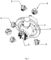
- Figure 1 discloses the rotatable ring 1, the electronic cylinder 2, thrusters 3, and the tank 7.
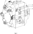
- an instantiation in an underwater vehicle is depicted in the Figure 2 and Figure 3 .
- the stabilizer (or passive pendulum component) comprises a rotating ring (or cylinder shaped) comprising:
- the floating element has a density from 100 to 600 Kg/m 3 , preferably 200 to 500 Kg/m 3 , more preferably from 300 to 450 Kg/m 3 .
- the rotating ring is built around the centre of buoyancy, and rotate over the y-axis (depending of the pitch of the mobile platform to stabilize).
- the rotating ring should have the maximum diameter that the platform restriction allows to maximize the stabilization performance and robustness to disturbances.
- the stabilizer further comprises a fix base, over which the mobile ring rotates.
- the rotating friction between the two parts should be low but enough to avoid the rotation with small disturbances in the platform.
- the stabilizer can have an optional locking system, that will fix the ring, endowing the platform with extra stabilization under high disturbances.
- This can be composed by an actuator device, such a solenoid or motor that releases a locking protrusion or locking dent from a dented ring attached to the rotating ring.
- Figure 4 shows the stabilizer (or passive pendulum component) comprising a rotatable ring. It can be seen the rotatable ring 1, the first sector region 4, the second sector region 5 and the locking actuator 6.
- VBS variable buoyancy system
- VBS variable buoyancy system
- the fluid deposit 7, typically comprising oil or water has its centre of buoyancy coincident or close to the platform centre of buoyancy.
- Figure 5 shows a ring shape.
- Figure 5 shows the second sector region 5, preferably a foam, an oil tank 7, preferably a pressurized oil tank fixed in relation to the main electronics; a container for oil for pump and control 8, preferably a pressurized container; support parts to hold the assembly in the center of the Y axis of the vehicle 9; a valve manifold 10 and rollers 11 attached to the rotatable ring to facilitate rotation.
- the pressurised container with pumping system may present two configurations, one with a bidirectional pump or one with a one way directional pump plus a set of valves to reverse the pumping direction. In both cases there are additionally an external access valve, pressure sensors and control electronics.
- This pumping system is capable of pumping the fluid from the fluid deposit in and out to and external bladder that holds the fluid, in that way increasing or decreasing the total volume, and so the buoyancy of the platform.
- the external bladder holds the fluid that is pumped in and out from the fluid deposit by the pumping system.
- This is typically a flexible bladder or a syringe that can be located in any part of the vehicle because the fluid that is pumping has similar weight than the surrounding water.
- the VBS allows the platform to control its buoyancy in order to be completely neutral and therefore avoiding unnecessary energy consumption to compensate any over or under weigh (see Figure 6).
- Figure 6 shows a further container 12, preferably a bladder, more preferably a flexible outer bladder comprising varying oil quantity; a flexible tubbing 13.
- a thruster 3 setup that allows pitch control is a minimal requirement for the energy efficient pitch control with stabilization of an underwater vehicle.
- the specific 6DoF thruster 3 actuator configuration depicted in the Figure 2 and Figure 3 allows redundant level of pitch control that associated with the other apparatus will allow the energy efficient, and self-stable pitch control.
- the mechanical actuation is done through a solenoid that causes the cogwheel to jam, blocking the movement of the pendulum.
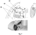
- Figure 7 shows a locking actuator 14, preferably solenoid; a locking protrusion 15, preferably a locking dent actuated by the solenoid to lock the rotatable ring; a recess 16 on the ring, preferably a dented ring attached to the rotatable ring.
- the underwater modular vehicle further comprises a camera/SLS configuration that allows a 360-degree field of view around the x axis of the robot, which points to the front of the robot, and adds high resolution 3D mapping capabilities.
- a camera/SLS configuration that allows a 360-degree field of view around the x axis of the robot, which points to the front of the robot, and adds high resolution 3D mapping capabilities.
- An example of this embodiment is show in Fig 2 .
- the underwater modular vehicle further comprises a camera/SLS configuration composed by one or more cameras and SLS, that allows frontal perception for 3D mapping or obstacle detection.
- the underwater modular vehicle further comprises a sonar configuration that allows the 360-degrees perception around the X axis, to ensure perception capability in low visibility scenarios, while moving along tunnels or vertical shafts.
- the underwater modular vehicle further comprises a sonar configuration that allows the frontal perception for obstacle detection in low visibility scenarios, while moving along tunnels or vertical shafts
- the underwater modular vehicle further comprises a multibeam sonar configuration that allows the frontal perception for longer range 3D mapping in low visibility scenarios.
- the underwater modular vehicle further comprises a set of navigation sensors to allow accurate and high-resolution dead reckoning capabilities.
- a set of navigation sensors to allow accurate and high-resolution dead reckoning capabilities.
- one or more High grade IMU inertial measurement system typically a FOG or RLG IMU; one or more DVL Dopler velocity logger, one or more Highly accurate pressure sensor.
- the dead reckoning system that fuses together all sensors data to achieve an high resolution navigation system.
- the dead reckoning data is fused with a factor graphs slam solution that incorporate visual and sonar measurements of relevant features (landmarks) in the environment to improve the navigation solution in longer missions, by creating relations between previous poses and landmarks.
- it has all motors controllers and main power control system in another housing pressure tolerant cylinder, that allows easy replacement, and allow a batteries power distribution through standard underwater connectors.
- the underwater modular vehicle further comprises one or several pressure tolerant batteries that can be quickly replaced in field and in operation.
Landscapes
- Engineering & Computer Science (AREA)
- Mechanical Engineering (AREA)
- Aviation & Aerospace Engineering (AREA)
- Control Of Position, Course, Altitude, Or Attitude Of Moving Bodies (AREA)
Priority Applications (1)
| Application Number | Priority Date | Filing Date | Title |
|---|---|---|---|
| PCT/IB2024/057471 WO2025027572A1 (fr) | 2023-08-01 | 2024-08-01 | Véhicule sous-marin pour espaces étroits |
Applications Claiming Priority (1)
| Application Number | Priority Date | Filing Date | Title |
|---|---|---|---|
| PT11885223 | 2023-08-01 |
Publications (1)
| Publication Number | Publication Date |
|---|---|
| EP4501774A1 true EP4501774A1 (fr) | 2025-02-05 |
Family
ID=94176872
Family Applications (1)
| Application Number | Title | Priority Date | Filing Date |
|---|---|---|---|
| EP23189601.0A Withdrawn EP4501774A1 (fr) | 2023-08-01 | 2023-08-03 | Véhicule sous-marin pour espaces étanches |
Country Status (1)
| Country | Link |
|---|---|
| EP (1) | EP4501774A1 (fr) |
Citations (6)
| Publication number | Priority date | Publication date | Assignee | Title |
|---|---|---|---|---|
| JPH05254485A (ja) * | 1992-03-13 | 1993-10-05 | Chubu Electric Power Co Inc | 水中ロボットの姿勢制御装置 |
| CN103832565A (zh) * | 2014-03-20 | 2014-06-04 | 北京邮电大学 | 一种摆式三推进器水下球形机器人 |
| CN106379505A (zh) * | 2016-11-18 | 2017-02-08 | 重庆邮电大学 | 一种具有变形能力的单摆差动式水下两栖机器人 |
| CN106741757A (zh) * | 2016-12-19 | 2017-05-31 | 东北石油大学 | 一种便携式水下机器人 |
| US20170190396A1 (en) * | 2015-12-30 | 2017-07-06 | Abb Technology Ag | Control mechanism for transformer in-situ inspection device |
| US20210089031A1 (en) | 2019-09-20 | 2021-03-25 | The United States Of America, As Represented By The Secretary Of The Navy | Spherical autonomous underwater vehicle |
-
2023
- 2023-08-03 EP EP23189601.0A patent/EP4501774A1/fr not_active Withdrawn
Patent Citations (6)
| Publication number | Priority date | Publication date | Assignee | Title |
|---|---|---|---|---|
| JPH05254485A (ja) * | 1992-03-13 | 1993-10-05 | Chubu Electric Power Co Inc | 水中ロボットの姿勢制御装置 |
| CN103832565A (zh) * | 2014-03-20 | 2014-06-04 | 北京邮电大学 | 一种摆式三推进器水下球形机器人 |
| US20170190396A1 (en) * | 2015-12-30 | 2017-07-06 | Abb Technology Ag | Control mechanism for transformer in-situ inspection device |
| CN106379505A (zh) * | 2016-11-18 | 2017-02-08 | 重庆邮电大学 | 一种具有变形能力的单摆差动式水下两栖机器人 |
| CN106741757A (zh) * | 2016-12-19 | 2017-05-31 | 东北石油大学 | 一种便携式水下机器人 |
| US20210089031A1 (en) | 2019-09-20 | 2021-03-25 | The United States Of America, As Represented By The Secretary Of The Navy | Spherical autonomous underwater vehicle |
Non-Patent Citations (9)
| Title |
|---|
| A. AGRAWALB. PRASADV. VISWANATHANS. K. PANDA: "Dynamic modeling of variable ballast tank for spherical underwater robot", PROC. IEEE INT. CONF. IND. TECHNOL. (ICIT), February 2013 (2013-02-01), pages 58 - 63, XP032377079, DOI: 10.1109/ICIT.2013.6505648 |
| A. AGRAWALB. PRASADV. VISWANATHANS. K. PANDA: "Dynamic modeling of variable ballast tank for spherical underwater robot", PROC. IEEE INT. CONF. IND. TECHNOL. (ICIT, February 2013 (2013-02-01), pages 58 - 63, XP032377079, DOI: 10.1109/ICIT.2013.6505648 |
| FERNANDEZ RAMON A SUAREZ ET AL: "Motion Control of Underwater Mine Explorer Robot UX-1: Field Trials", IEEE ACCESS, vol. 7, 23 July 2019 (2019-07-23), pages 99782 - 99803, XP011738081, DOI: 10.1109/ACCESS.2019.2930544 * |
| H. T. CHOIA. HANAIS. K. CHOIJ. YUH: "Development of an underwater robot ODIN-III", PROC. IEEE/RSJ INT. CONF. INTELL. ROBOTS SYST. (IROS, October 2003 (2003-10-01), pages 836 - 841, XP010672611, DOI: 10.1109/IROS.2003.1250733 |
| LOPE ET AL.: "UNEXMIN: A new concept to sustainably obtain geological information from flooded mine", EUROPEAN GEOLOGIST JOURNAL, pages 54 - 57 |
| S. A. WATSOND. J. P. CRUTCHLEYP. N. GREEN: "The design and technical challenges of a micro-autonomous underwater vehicle (µAUV", PROC. IEEE INT. CONF. MECHATRONICS AUTOMAT., pages 567 - 572 |
| S. A. WATSONP. N. GREEN: "Design considerations for micro-autonomous underwater vehicles (µAUVs", PROC. IEEE CONF. ROBOT. AUTOMAT. MECHATRONICS, December 2010 (2010-12-01), pages 429 - 434 |
| Y. LIS. GUOY. WANG: "Design and characteristics evaluation of a novel spherical underwater robot", ROBOT. AUTON. SYST., vol. 94, August 2017 (2017-08-01), pages 61 - 74 |
| ZAVARI SOHEIL ET AL: "Propulsion system development and power consumption in an autonomous underwater vehicle", 2019 23RD INTERNATIONAL CONFERENCE ON SYSTEM THEORY, CONTROL AND COMPUTING (ICSTCC), IEEE, 9 October 2019 (2019-10-09), pages 521 - 524, XP033652728, DOI: 10.1109/ICSTCC.2019.8885503 * |
Similar Documents
| Publication | Publication Date | Title |
|---|---|---|
| Ribas et al. | Girona 500 AUV: From survey to intervention | |
| KR101128032B1 (ko) | 다자유도 무인 수상 로봇 기반의 수중 작업 로봇 | |
| EP2130760B1 (fr) | Véhicule submersible | |
| CN109367738B (zh) | 一种水下自主作业机器人及其作业方法 | |
| US20110297070A1 (en) | Propulsion System for an Autonomous Underwater Vehicle | |
| US10196117B2 (en) | Autonomous unmanned underwater vehicles | |
| JP6523568B2 (ja) | 水中ドローン | |
| Vaganay et al. | Ship hull inspection by hull-relative navigation and control | |
| CN107117266B (zh) | 一种自平衡装置、无人航行器及其控制系统 | |
| US20180297678A1 (en) | Underwater vehicle | |
| WO2016023080A1 (fr) | Embarcation destinée à la réalisation d'opérations en surface | |
| US20240227997A9 (en) | Hybrid propeller/undulating fin propulsion for aquatic vehicles | |
| EP4501774A1 (fr) | Véhicule sous-marin pour espaces étanches | |
| KR20180064636A (ko) | 해양 탐사 로봇 및 해양 탐사 로봇에 장착되는 다리 | |
| US20240239457A1 (en) | An underwater probe or submersible | |
| Hover et al. | A vehicle system for autonomous relative survey of in-water ships | |
| Brown et al. | An overview of autonomous underwater vehicle research and testbed at PeRL | |
| Martins et al. | MARA-A modular underwater robot for confined spaces exploration | |
| WO2025027572A1 (fr) | Véhicule sous-marin pour espaces étroits | |
| Cruz et al. | DART—A portable deep water hovering AUV | |
| CN218288092U (zh) | 一种多功能模块化深海环境监测无人潜航器 | |
| Pyo et al. | Development of AUV (MI) for strong ocean current and zero-visibility condition | |
| Gage et al. | Low-cost unmanned underwater vehicles for multi-vehicle autonomy testing | |
| Stone et al. | Sub-ice autonomous underwater vehicle architectures for ocean world exploration and life search | |
| Caccia et al. | Sonar-based guidance of unmanned underwater vehicles |
Legal Events
| Date | Code | Title | Description |
|---|---|---|---|
| PUAI | Public reference made under article 153(3) epc to a published international application that has entered the european phase |
Free format text: ORIGINAL CODE: 0009012 |
|
| STAA | Information on the status of an ep patent application or granted ep patent |
Free format text: STATUS: THE APPLICATION HAS BEEN PUBLISHED |
|
| AK | Designated contracting states |
Kind code of ref document: A1 Designated state(s): AL AT BE BG CH CY CZ DE DK EE ES FI FR GB GR HR HU IE IS IT LI LT LU LV MC ME MK MT NL NO PL PT RO RS SE SI SK SM TR |
|
| STAA | Information on the status of an ep patent application or granted ep patent |
Free format text: STATUS: THE APPLICATION IS DEEMED TO BE WITHDRAWN |
|
| 18D | Application deemed to be withdrawn |
Effective date: 20250806 |