EP4501756A1 - Vehicle body lateral section structure - Google Patents
Vehicle body lateral section structure Download PDFInfo
- Publication number
- EP4501756A1 EP4501756A1 EP23815691.3A EP23815691A EP4501756A1 EP 4501756 A1 EP4501756 A1 EP 4501756A1 EP 23815691 A EP23815691 A EP 23815691A EP 4501756 A1 EP4501756 A1 EP 4501756A1
- Authority
- EP
- European Patent Office
- Prior art keywords
- side sill
- vehicle
- cross member
- floor cross
- width direction
- Prior art date
- Legal status (The legal status is an assumption and is not a legal conclusion. Google has not performed a legal analysis and makes no representation as to the accuracy of the status listed.)
- Pending
Links
Images
Classifications
-
- B—PERFORMING OPERATIONS; TRANSPORTING
- B62—LAND VEHICLES FOR TRAVELLING OTHERWISE THAN ON RAILS
- B62D—MOTOR VEHICLES; TRAILERS
- B62D21/00—Understructures, i.e. chassis frame on which a vehicle body may be mounted
- B62D21/15—Understructures, i.e. chassis frame on which a vehicle body may be mounted having impact absorbing means, e.g. a frame designed to permanently or temporarily change shape or dimension upon impact with another body
- B62D21/157—Understructures, i.e. chassis frame on which a vehicle body may be mounted having impact absorbing means, e.g. a frame designed to permanently or temporarily change shape or dimension upon impact with another body for side impacts
-
- B—PERFORMING OPERATIONS; TRANSPORTING
- B60—VEHICLES IN GENERAL
- B60K—ARRANGEMENT OR MOUNTING OF PROPULSION UNITS OR OF TRANSMISSIONS IN VEHICLES; ARRANGEMENT OR MOUNTING OF PLURAL DIVERSE PRIME-MOVERS IN VEHICLES; AUXILIARY DRIVES FOR VEHICLES; INSTRUMENTATION OR DASHBOARDS FOR VEHICLES; ARRANGEMENTS IN CONNECTION WITH COOLING, AIR INTAKE, GAS EXHAUST OR FUEL SUPPLY OF PROPULSION UNITS IN VEHICLES
- B60K1/00—Arrangement or mounting of electrical propulsion units
- B60K1/04—Arrangement or mounting of electrical propulsion units of the electric storage means for propulsion
-
- B—PERFORMING OPERATIONS; TRANSPORTING
- B62—LAND VEHICLES FOR TRAVELLING OTHERWISE THAN ON RAILS
- B62D—MOTOR VEHICLES; TRAILERS
- B62D25/00—Superstructure or monocoque structure sub-units; Parts or details thereof not otherwise provided for
- B62D25/02—Side panels
- B62D25/025—Side sills thereof
-
- B—PERFORMING OPERATIONS; TRANSPORTING
- B62—LAND VEHICLES FOR TRAVELLING OTHERWISE THAN ON RAILS
- B62D—MOTOR VEHICLES; TRAILERS
- B62D25/00—Superstructure or monocoque structure sub-units; Parts or details thereof not otherwise provided for
- B62D25/20—Floors or bottom sub-units
- B62D25/2009—Floors or bottom sub-units in connection with other superstructure subunits
- B62D25/2036—Floors or bottom sub-units in connection with other superstructure subunits the subunits being side panels, sills or pillars
-
- B—PERFORMING OPERATIONS; TRANSPORTING
- B60—VEHICLES IN GENERAL
- B60K—ARRANGEMENT OR MOUNTING OF PROPULSION UNITS OR OF TRANSMISSIONS IN VEHICLES; ARRANGEMENT OR MOUNTING OF PLURAL DIVERSE PRIME-MOVERS IN VEHICLES; AUXILIARY DRIVES FOR VEHICLES; INSTRUMENTATION OR DASHBOARDS FOR VEHICLES; ARRANGEMENTS IN CONNECTION WITH COOLING, AIR INTAKE, GAS EXHAUST OR FUEL SUPPLY OF PROPULSION UNITS IN VEHICLES
- B60K1/00—Arrangement or mounting of electrical propulsion units
- B60K1/04—Arrangement or mounting of electrical propulsion units of the electric storage means for propulsion
- B60K2001/0405—Arrangement or mounting of electrical propulsion units of the electric storage means for propulsion characterised by their position
- B60K2001/0438—Arrangement under the floor
-
- B—PERFORMING OPERATIONS; TRANSPORTING
- B60—VEHICLES IN GENERAL
- B60Y—INDEXING SCHEME RELATING TO ASPECTS CROSS-CUTTING VEHICLE TECHNOLOGY
- B60Y2200/00—Type of vehicle
- B60Y2200/90—Vehicles comprising electric prime movers
- B60Y2200/91—Electric vehicles
-
- B—PERFORMING OPERATIONS; TRANSPORTING
- B60—VEHICLES IN GENERAL
- B60Y—INDEXING SCHEME RELATING TO ASPECTS CROSS-CUTTING VEHICLE TECHNOLOGY
- B60Y2306/00—Other features of vehicle sub-units
- B60Y2306/01—Reducing damages in case of crash, e.g. by improving battery protection
Definitions
- the present invention relates to an automotive body side structure such as a battery powered vehicle (battery electric vehicle) in which a battery pack is disposed vehicle inside in the vehicle width direction relative to a side sill.
- a battery powered vehicle battery electric vehicle
- a battery pack is disposed vehicle inside in the vehicle width direction relative to a side sill.
- a battery pack accommodating a large battery is disposed on a floor portion of a lower part of a vehicle body.
- a lithium (Li) based material is often used for the battery, when the battery pack is damaged at the time of a collision and liquid leakage from the battery occurs, there is a possibility of fire, and thus a structure for protecting the battery pack is required.
- the battery pack is protected by a floor cross member extending in the vehicle width direction and side sills extending in the vehicle length direction both outsides of the vehicle in the vehicle width direction, with the floor cross member displaced between the two side sills and the battery pack placed below the floor cross member.
- Patent Literature 1 discloses a structure in which, in a vehicle including a battery pack, a side sill extending in a front-rear direction of a vehicle body at an outer side in a vehicle width direction, and a floor cross member bridged between left and right side sills, both end portions of the floor cross member are connected to a joint portion between the side sill inner and the side sill outer from a vehicle inner side side portion of the side sill inner in the side sill.
- the present invention has been made to solve the above problems, and an object thereof is to provide an automotive body side structure capable of protecting a battery pack by reducing a load transferred to the battery pack at a time of a side collision of a vehicle body at a time of a side collision of the vehicle body, the automotive body side structure including a side sill, a battery pack disposed vehicle inside in a vehicle width direction relative to the side sill, and a floor cross member.
- An automotive body side structure includes: a side sill formed by joining a side sill inner and a side sill outer extending in a front-rear direction of a vehicle body at a vehicle outer side in the vehicle width direction of the vehicle body at an upper end portion and a lower end portion in a vehicle height direction; a battery pack disposed at a lower part of the vehicle body vehicle inside in the vehicle width direction relative to the side sill; and a floor cross member extending in the vehicle width direction above the side sill vehicle inside in the vehicle width direction, wherein the floor cross member is made of a metal sheet having a tensile strength of 1180 MPa-class or more, and includes a vehicle outer side end portion in the vehicle width direction not contacting a vehicle inner side face of the side sill inner in the vehicle width direction, the end portion being disposed so as to cover an upper portion of the side sill inner in the vehicle height direction, the end portion extending to and contacting a joining surface portion at the upper end portion of the side sill inner and the side
- the floor cross member may have a groove shape extending in the vehicle width direction, a wall face portion contacting the joining surface portion may be provided at a distal end of the floor cross member, and a groove shape of an end portion of the floor cross member may be closed by the wall face portion.
- the end portion of the floor cross member may be connected to the joining surface portion between the side sill inner and the side sill outer.
- the floor cross member has a load transfer path of a load input to the vehicle body at the time of a side collision, and a reaction force to vehicle outside in the vehicle width direction by the floor cross member is mainly applied to a joining surface portion where the side sill inner and the side sill outer are joined.
- the side sill outer is crushed to compressive deformation to absorb collision energy, but the form of the side sill inner can be maintained without being crushed.
- the floor cross member is made of a metal sheet having a tensile strength of 1180 MPa or more, even after the side sill outer is compressed and deformed and crushed, the load input to the side sill can be continuously received without deforming the floor cross member.
- the side sill inner is hardly deformed and crushed, and the collision energy absorption capacity (impact energy absorption capacity) can be maintained, so that the load transfer to a battery pack 5 can be reduced.
- deformation of the battery pack 5 can be suppressed at the time of a side collision, the battery pack can be protected from damage, and a safe vehicle can be made.
- an automotive body side structure 1 includes a side sill 3, a battery pack 5, a floor cross member 7, and a floor panel 9.
- FIG. 1 illustrates other vehicle body components such as a floor panel 9 disposed above the battery pack 5.
- vehicle body components are not essential parts of the present invention, and thus the description thereof is omitted.
- elements having the same functional configuration are denoted by the same reference numerals, and redundant description will be omitted.
- the side sill 3 includes a side sill inner 3a and a side sill outer 3b extending in the front-rear direction of the vehicle body at the vehicle outer side of the vehicle body in the vehicle width direction.
- the side sill inner 3a has a groove shape opened toward vehicle outside in the vehicle width direction by a top portion 3a1 and the pair of side walls 3a2, and the side sill outer 3b has a groove shape opened toward vehicle inside in the vehicle width direction.
- the side sill inner 3a and the side sill outer 3b are joined to each other at an upper end portion 3c and a lower end portion (not illustrated) in the vehicle height direction with their openings facing each other to form a closed cross section structure.
- the automotive body side structure 1 illustrated in FIG. 1 illustrates a range of about 1/3 or more of the upper part of the side sill 3 in the vehicle height direction.
- the side sill inner 3a and the side sill outer 3b have, for example, a hat-shaped cross-sectional shape including a top portion, a pair of side walls (vertical walls), and a pair of flange portions, and flange portions at an upper end portion and a lower end portion of the side sill inner 3a and the side sill outer 3b are joined to each other to form the side sill 3 having a closed cross section structure.
- the side sill inner and the side sill outer are not limited to those having the hat-shaped cross-sectional shape, and it is sufficient that the upper end portion and the lower end portion of each of the side sill inner and the side sill outer are joined to constitute a side sill having a closed cross section structure.
- the battery pack 5 is disposed at a lower part of the vehicle body vehicle inside in the vehicle width direction relative to the side sill 3, and a battery cell (not illustrated) is mounted inside the battery pack 5.
- the floor cross member 7 has a hat-shaped cross-sectional shape including a bottom surface (bottom portion), a pair of side walls, and a pair of flange portions, and has a groove shape extending in the vehicle width direction by the bottom surface and the pair of side walls. As illustrated in FIG. 1 , the floor cross member 7 extends in the vehicle width direction above the side sill 3 vehicle inside in the vehicle width direction. In the cross-sectional view of the automotive body side structure of FIG. 1 , a cross section of the bottom surface is displayed.
- the floor cross member 7 is made of a metal sheet having a tensile strength of 1180 MPa-class or more.
- the vehicle outer side end portion 7a in the vehicle width direction is disposed so as not to contact the vehicle inner side face of the side sill inner 3a in the vehicle width direction but to cover the upper portion of the side sill inner 3a in the vehicle height direction. Further, the end portion extends to a joining surface portion 3d where the side sill inner 3a and the side sill outer 3b are joined and contact them.
- the upper portion of the side sill inner 3a in the vehicle height direction refers to a side wall 3a2 in a case where the side sill inner 3a has a hat-shaped cross-sectional shape including a top portion 3a1, a side wall 3a2, and a flange portion 3a3 as illustrated in FIG. 1 .
- the vehicle inner side face of the side sill inner 3a in the vehicle width direction refers to a top portion 3a1.
- the side sill outer 3b is compressed and deformed and crushed by the collision load input to the side sill 3 at a time of a side collision in which the collision load is input to the side sill 3 from vehicle outside in the vehicle width direction. After the side sill outer 3b is crushed, the load transferred to the battery pack 5 is reduced by continuously receiving the load input to the side sill 3 without deforming the floor cross member 7.
- an end portion 23a of the floor cross member 23 in the vehicle width direction extends to the upper side of the side sill inner 3a, but is not in contact with the joining surface portion 3d of the upper end portion 3c of the side sill 3. Therefore, in a case where a load is input to the side sill 3 at the time of a side collision, first, the side sill outer 3b is deformed and crushed, and then the load is not sufficiently transferred to the floor cross member 23, and the load transfer to the battery pack 5 cannot be sufficiently reduced.
- the side sill outer 3b is crushed to compressive deformation to absorb collision energy, but the form of the side sill inner 3a can be maintained without being crushed.
- the floor cross member 7 is made of a metal sheet having a tensile strength of 1180 MPa or more, even after the side sill outer 3b is compressed and deformed and crushed, the load input to the side sill 3 can be continuously received without deforming the floor cross member 7.
- the side sill inner is hardly deformed and crushed, and the collision energy absorption capacity can be maintained, so that the load transfer to the battery pack 5 can be reduced.
- deformation of the battery pack 5 can be suppressed at the time of a side collision, the battery pack 5 can be protected from damage, and a safe vehicle can be made.
- the floor cross member 7 is made of a metal sheet having a tensile strength of 1180 MPa-class or more.
- the floor cross member 7 is easily deformed when a load is transferred to the floor cross member, the load cannot be sufficiently transferred, and the load transferred to the battery pack 5 cannot be reduced.
- the end portion 7a of the floor cross member 7 contacts the joining surface portion 3d where the side sill inner 3a and the side sill outer 3b are joined, but is not connected.
- the end portion of the floor cross member is preferably connected to the joining surface portion between the side sill inner and the side sill outer. Accordingly, at a time of a side collision, the end portion of the floor cross member and the joining surface portion between the side sill inner and the side sill outer are less likely to be displaced from each other, and the load transfer path of the load input to the vehicle body (side sill) to the floor cross member can be maintained, so that the load can be more easily transferred to the floor cross member, and the load transferred to the battery pack can be further reduced.
- the floor cross member 7 has a groove shape (not illustrated) which includes a bottom surface and a pair of side walls and extends in the vehicle width direction, and for example, as illustrated in FIG. 1 , a wall face portion 7b which is bent from a bottom surface 7a1 and continues is provided at a distal end of the end portion 7a, and the groove shape of the end portion 7a of the floor cross member 7 is closed by a wall face portion 7b.
- a wall face portion 7b which is bent from a bottom surface 7a1 and continues is provided at a distal end of the end portion 7a, and the groove shape of the end portion 7a of the floor cross member 7 is closed by a wall face portion 7b.
- FIG. 3 A specific example of a shape in which the groove shape is closed at the end portion 7a of the floor cross member 7 in the vehicle width direction is illustrated in FIG. 3 .
- a bottom surface 7a1, a pair of side walls 7a2, and a wall face portion 7b are integrated and continuous at the distal end of the end portion 7a, so that the groove shape is a closed shape.
- the floor cross member 7 illustrated in FIG. 3(b) has a high side wall height (height in the vehicle height direction)
- the groove-shaped bottom surface 7a1 and the wall face portion 7b at the distal end are bent and continuous, but the groove-shaped bottom surface 7a1 and the pair of side walls 7a2 are not integrated and continuous.
- a welding margin 7c bent toward the side wall 7a2 is provided on both side portions of the bottom surface 7a1 and the wall face portion 7b, and the welding margin 7c and the side wall 7a2 are joined by spot welding or the like, so that the groove shape is a closed shape.
- side collision analysis in which a pole 103 collide from vehicle outside in the vehicle width direction as illustrated in FIG. 4 was performed on a vehicle 101 including the automotive body side structure 1 (Invention Example) including the side sill 3, the battery pack 5, and the floor cross member 7 illustrated in FIG. 1 in the above-described embodiment.
- the battery pack 5 is supported by a battery frame assembly 11 disposed on the outer peripheral side in the vehicle width direction.
- the battery frame assembly 11 includes a plurality of steel sheet parts.
- the vehicle 101 was accelerated to 29 km/h in the vehicle width direction, and collided with the pole 103 which is a rigid body with respect to the side face of the vehicle 101.
- the side sill 3 (see FIG. 1 ) is locally deformed and advances inside the vehicle. Therefore, in the present example, the deformation amount of the battery pack 5 in the side collision process and the load input to the battery pack 5 were evaluated.
- the deformation amount of the battery pack 5 As for the deformation amount of the battery pack 5, as illustrated in FIG. 5(a) , lengths in the vehicle width direction of the battery pack 5 before and after deformation were measured at a plurality of positions in the vehicle length direction (positions indicated by arrows in FIG. 5(a) ), and a difference between before and after deformation was obtained.
- the reaction force contact reaction force generated in the battery frame assembly 11 by the contact of a connecting member 13 provided on the outer peripheral side in the vehicle width direction of the battery frame assembly 11 was obtained.
- an end portion 23a of the floor cross member 23 in the vehicle width direction extends so as to cover the side sill inner 3a, but does not contact the joining surface portion 3d between the side sill inner 3a and the side sill outer 3b.
- an end portion 33a of the floor cross member 33 in the vehicle width direction does not extend above the side sill inner 3a.
- the deformation amount of the battery pack 5 in the Invention Example and the Comparative Example 1 was smaller than that in the Comparative Example 2 in which the end portion 33a of the floor cross member 33 did not extend above the side sill inner 3a.
- the deformation amount of the battery pack 5 was smaller in the Invention Example.
- the load input to the battery pack 5 in the Invention Example and the Comparative Example 1 was smaller than that in the Comparative Example 2 in which the end portion 33a of the floor cross member 33 did not extend above the side sill inner 3a.
- the load input to the battery pack 5 was smaller in the Invention Example.
- the load input to the vehicle is transferred to the floor cross member at a time of a side collision, so that the load input to the battery pack can be sufficiently reduced, the deformation amount of the battery pack can be reduced, and the battery pack can be protected.
- an automotive body side structure capable of protecting a battery pack by reducing a load transferred to the battery pack at a time of a side collision of a vehicle body at a time of a side collision of the vehicle body at a time of a side collision of the vehicle body, the automotive body side structure including the side sill, the battery pack disposed vehicle inside in the vehicle width direction of the side sill, and the floor cross member.
Landscapes
- Engineering & Computer Science (AREA)
- Chemical & Material Sciences (AREA)
- Combustion & Propulsion (AREA)
- Transportation (AREA)
- Mechanical Engineering (AREA)
- Body Structure For Vehicles (AREA)
- Arrangement Or Mounting Of Propulsion Units For Vehicles (AREA)
Abstract
Description
- The present invention relates to an automotive body side structure such as a battery powered vehicle (battery electric vehicle) in which a battery pack is disposed vehicle inside in the vehicle width direction relative to a side sill.
- In recent years, particularly in the automobile industry, replacement from a gasoline engine car due to environmental problems to a battery powered vehicle is in progress. In a battery powered vehicle or the like, a battery pack accommodating a large battery is disposed on a floor portion of a lower part of a vehicle body. Further, since a lithium (Li) based material is often used for the battery, when the battery pack is damaged at the time of a collision and liquid leakage from the battery occurs, there is a possibility of fire, and thus a structure for protecting the battery pack is required. The battery pack is protected by a floor cross member extending in the vehicle width direction and side sills extending in the vehicle length direction both outsides of the vehicle in the vehicle width direction, with the floor cross member displaced between the two side sills and the battery pack placed below the floor cross member.
- As a technique for protecting a battery pack at the time of a side collision (side impact collision) of a battery powered vehicle or the like, for example,
Patent Literature 1 discloses a structure in which, in a vehicle including a battery pack, a side sill extending in a front-rear direction of a vehicle body at an outer side in a vehicle width direction, and a floor cross member bridged between left and right side sills, both end portions of the floor cross member are connected to a joint portion between the side sill inner and the side sill outer from a vehicle inner side side portion of the side sill inner in the side sill. - Patent Literature 1:
JP 6734709 B - In the technique disclosed in
Patent Literature 1, at the time of a side collision in which a load is input when a pole or the like collides with a side sill at a side face of the vehicle, the collision load is transferred from the side sill to the floor cross member via a connection portion between the side sill and the floor cross member extending from a vehicle inner side side portion of the side sill inner to a joint portion between the side sill outer and the side sill inner. The reaction force is amplified by the floor cross member to crush the side sill outer and the side sill inner, and the side sill outer and the side sill inner are crushed to compressive deformation to efficiently absorb the collision energy (crush energy). However, when the side sill is crushed first, the load transferred to the battery pack cannot be sufficiently reduced, and the battery pack cannot be sufficiently protected. - The present invention has been made to solve the above problems, and an object thereof is to provide an automotive body side structure capable of protecting a battery pack by reducing a load transferred to the battery pack at a time of a side collision of a vehicle body at a time of a side collision of the vehicle body, the automotive body side structure including a side sill, a battery pack disposed vehicle inside in a vehicle width direction relative to the side sill, and a floor cross member.
- An automotive body side structure according to the present invention includes: a side sill formed by joining a side sill inner and a side sill outer extending in a front-rear direction of a vehicle body at a vehicle outer side in the vehicle width direction of the vehicle body at an upper end portion and a lower end portion in a vehicle height direction; a battery pack disposed at a lower part of the vehicle body vehicle inside in the vehicle width direction relative to the side sill; and a floor cross member extending in the vehicle width direction above the side sill vehicle inside in the vehicle width direction, wherein the floor cross member is made of a metal sheet having a tensile strength of 1180 MPa-class or more, and includes a vehicle outer side end portion in the vehicle width direction not contacting a vehicle inner side face of the side sill inner in the vehicle width direction, the end portion being disposed so as to cover an upper portion of the side sill inner in the vehicle height direction, the end portion extending to and contacting a joining surface portion at the upper end portion of the side sill inner and the side sill outer, and wherein at a time of a side collision in which a collision load is input to the side sill from vehicle outside in the vehicle width direction, a load transferred to the battery pack is reduced by transferring a load input to the side sill to the floor cross member after the side sill outer is deformed and crushed.
- The floor cross member may have a groove shape extending in the vehicle width direction, a wall face portion contacting the joining surface portion may be provided at a distal end of the floor cross member, and a groove shape of an end portion of the floor cross member may be closed by the wall face portion.
- The end portion of the floor cross member may be connected to the joining surface portion between the side sill inner and the side sill outer.
- In the present invention, the floor cross member has a load transfer path of a load input to the vehicle body at the time of a side collision, and a reaction force to vehicle outside in the vehicle width direction by the floor cross member is mainly applied to a joining surface portion where the side sill inner and the side sill outer are joined. As a result, the side sill outer is crushed to compressive deformation to absorb collision energy, but the form of the side sill inner can be maintained without being crushed. Further, since the floor cross member is made of a metal sheet having a tensile strength of 1180 MPa or more, even after the side sill outer is compressed and deformed and crushed, the load input to the side sill can be continuously received without deforming the floor cross member. As a result, the side sill inner is hardly deformed and crushed, and the collision energy absorption capacity (impact energy absorption capacity) can be maintained, so that the load transfer to a
battery pack 5 can be reduced. As a result, deformation of thebattery pack 5 can be suppressed at the time of a side collision, the battery pack can be protected from damage, and a safe vehicle can be made. -
-
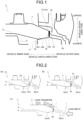
FIG. 1 is a diagram illustrating an automotive body side structure according to an embodiment of the present invention. -
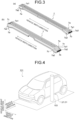
FIG. 2 is a view for describing transfer of a load at the time of a side collision in the automotive body side structure according to the embodiment of the present invention ((a) Conventional automotive body side structure, (b) automotive body side structure according to present embodiment, and (c) Load transfer path at the time of side collision). -
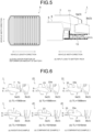
FIG. 3 is a diagram illustrating a specific example of a shape in which an end portion of a floor cross member is closed in the side structure of the vehicle body according to the embodiment of the present invention. -
FIG. 4 is a diagram for describing a side collision of a vehicle body to be analyzed in the example. -
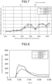
FIG. 5 is a diagram illustrating a deformation amount of a battery pack and a method of evaluating an input load to the battery pack in an example ((a) Evaluation position of deformation amount of battery pack, (b) Input load to battery pack). -
FIG. 6 is a cross-sectional view of the automotive body side structure according to the Invention Example and Comparative Examples 1 and 2 in the example at (i) the vehicle length direction position TL=1568 mm and (ii) the vehicle length direction position TL=1916 mm ((a) Invention Example, (b) Comparative Example 1, (c) Comparative Example 2). -
FIG. 7 is a graph illustrating a result of a deformation amount of the battery pack in a case where a pole collides with a vehicle length direction position TL=1916 mm in the example. -
FIG. 8 is a graph illustrating a result of a contact reaction force obtained as an input load to the battery pack when a pole collides with a vehicle length direction position TL=1916 mm in the example. - As illustrated in
FIG. 1 as an example, an automotivebody side structure 1 according to the embodiment of the present invention includes aside sill 3, abattery pack 5, afloor cross member 7, and afloor panel 9. - Hereinafter, an automotive
body side structure 1 according to the present embodiment will be described with reference toFIG. 1. FIG. 1 illustrates other vehicle body components such as afloor panel 9 disposed above thebattery pack 5. However, in the following description, these vehicle body components are not essential parts of the present invention, and thus the description thereof is omitted. Furthermore, in the present specification and the drawings, elements having the same functional configuration are denoted by the same reference numerals, and redundant description will be omitted. - As illustrated in
FIG. 1 , theside sill 3 includes a side sill inner 3a and a side sill outer 3b extending in the front-rear direction of the vehicle body at the vehicle outer side of the vehicle body in the vehicle width direction. The side sill inner 3a has a groove shape opened toward vehicle outside in the vehicle width direction by a top portion 3a1 and the pair of side walls 3a2, and the side sill outer 3b has a groove shape opened toward vehicle inside in the vehicle width direction. The side sill inner 3a and the side sill outer 3b are joined to each other at anupper end portion 3c and a lower end portion (not illustrated) in the vehicle height direction with their openings facing each other to form a closed cross section structure. - The automotive
body side structure 1 illustrated inFIG. 1 illustrates a range of about 1/3 or more of the upper part of theside sill 3 in the vehicle height direction. The side sill inner 3a and the side sill outer 3b have, for example, a hat-shaped cross-sectional shape including a top portion, a pair of side walls (vertical walls), and a pair of flange portions, and flange portions at an upper end portion and a lower end portion of the side sill inner 3a and the side sill outer 3b are joined to each other to form theside sill 3 having a closed cross section structure. However, in the present invention, the side sill inner and the side sill outer are not limited to those having the hat-shaped cross-sectional shape, and it is sufficient that the upper end portion and the lower end portion of each of the side sill inner and the side sill outer are joined to constitute a side sill having a closed cross section structure. - As illustrated in
FIG. 1 , thebattery pack 5 is disposed at a lower part of the vehicle body vehicle inside in the vehicle width direction relative to theside sill 3, and a battery cell (not illustrated) is mounted inside thebattery pack 5. - The
floor cross member 7 has a hat-shaped cross-sectional shape including a bottom surface (bottom portion), a pair of side walls, and a pair of flange portions, and has a groove shape extending in the vehicle width direction by the bottom surface and the pair of side walls. As illustrated inFIG. 1 , thefloor cross member 7 extends in the vehicle width direction above theside sill 3 vehicle inside in the vehicle width direction. In the cross-sectional view of the automotive body side structure ofFIG. 1 , a cross section of the bottom surface is displayed. Thefloor cross member 7 is made of a metal sheet having a tensile strength of 1180 MPa-class or more. The vehicle outerside end portion 7a in the vehicle width direction is disposed so as not to contact the vehicle inner side face of the side sill inner 3a in the vehicle width direction but to cover the upper portion of the side sill inner 3a in the vehicle height direction. Further, the end portion extends to a joiningsurface portion 3d where the side sill inner 3a and the side sill outer 3b are joined and contact them. The upper portion of the side sill inner 3a in the vehicle height direction refers to a side wall 3a2 in a case where the side sill inner 3a has a hat-shaped cross-sectional shape including a top portion 3a1, a side wall 3a2, and a flange portion 3a3 as illustrated inFIG. 1 . The vehicle inner side face of the side sill inner 3a in the vehicle width direction refers to a top portion 3a1. - In the automotive
body side structure 1, the side sill outer 3b is compressed and deformed and crushed by the collision load input to theside sill 3 at a time of a side collision in which the collision load is input to theside sill 3 from vehicle outside in the vehicle width direction. After the side sill outer 3b is crushed, the load transferred to thebattery pack 5 is reduced by continuously receiving the load input to theside sill 3 without deforming thefloor cross member 7. - The operation and effect of the automotive
body side structure 1 according to the present embodiment is as follows. In a conventional automotivebody side structure 21 including theside sill 3, thebattery pack 5, and afloor cross member 23 as illustrated inFIG. 2(a) as an example, anend portion 23a of thefloor cross member 23 in the vehicle width direction extends to the upper side of the side sill inner 3a, but is not in contact with the joiningsurface portion 3d of theupper end portion 3c of theside sill 3. Therefore, in a case where a load is input to theside sill 3 at the time of a side collision, first, the side sill outer 3b is deformed and crushed, and then the load is not sufficiently transferred to thefloor cross member 23, and the load transfer to thebattery pack 5 cannot be sufficiently reduced. - On the other hand, according to the automotive
body side structure 1 of the present embodiment, as illustrated inFIGS. 1 and 2(b) , theend portion 7a of thefloor cross member 7 is in contact with thejoining surface portion 3d of theupper end portion 3c of theside sill 3, so that thefloor cross member 7 has a load transfer path of the load input to the vehicle body at the time of the side collision as illustrated inFIG. 2(c) . The reaction force toward vehicle outside in the vehicle width direction by thefloor cross member 7 is mainly applied to the joiningsurface portion 3d where the side sill inner 3a and the side sill outer 3b are joined. As a result, the side sill outer 3b is crushed to compressive deformation to absorb collision energy, but the form of the side sill inner 3a can be maintained without being crushed. Further, since thefloor cross member 7 is made of a metal sheet having a tensile strength of 1180 MPa or more, even after the side sill outer 3b is compressed and deformed and crushed, the load input to theside sill 3 can be continuously received without deforming thefloor cross member 7. As a result, the side sill inner is hardly deformed and crushed, and the collision energy absorption capacity can be maintained, so that the load transfer to thebattery pack 5 can be reduced. As a result, deformation of thebattery pack 5 can be suppressed at the time of a side collision, thebattery pack 5 can be protected from damage, and a safe vehicle can be made. - In the present embodiment, the
floor cross member 7 is made of a metal sheet having a tensile strength of 1180 MPa-class or more. However, in a case where thefloor cross member 7 is made of a metal sheet having a tensile strength of less than 1180 MPa, thefloor cross member 7 is easily deformed when a load is transferred to the floor cross member, the load cannot be sufficiently transferred, and the load transferred to thebattery pack 5 cannot be reduced. - Therefore, in the present embodiment, the
floor cross member 7 is made of a metal sheet having a tensile strength of 1180 MPa-class or more, and specifically, steel sheets having tensile strengths of 1180 MPa-class, 1370 MPa-class, 1470 MPa-class, and 1760 MPa-class are exemplified. - In the automotive
body side structure 1, theend portion 7a of thefloor cross member 7 contacts the joiningsurface portion 3d where the side sill inner 3a and the side sill outer 3b are joined, but is not connected. However, in the present invention, the end portion of the floor cross member is preferably connected to the joining surface portion between the side sill inner and the side sill outer. Accordingly, at a time of a side collision, the end portion of the floor cross member and the joining surface portion between the side sill inner and the side sill outer are less likely to be displaced from each other, and the load transfer path of the load input to the vehicle body (side sill) to the floor cross member can be maintained, so that the load can be more easily transferred to the floor cross member, and the load transferred to the battery pack can be further reduced. - Further, in the present invention, it is preferable that the
floor cross member 7 has a groove shape (not illustrated) which includes a bottom surface and a pair of side walls and extends in the vehicle width direction, and for example, as illustrated inFIG. 1 , awall face portion 7b which is bent from a bottom surface 7a1 and continues is provided at a distal end of theend portion 7a, and the groove shape of theend portion 7a of thefloor cross member 7 is closed by awall face portion 7b. As a result, theend portion 7a of thefloor cross member 7 is hardly crushed, and the vehicle body can be prevented from being greatly deformed. - A specific example of a shape in which the groove shape is closed at the
end portion 7a of thefloor cross member 7 in the vehicle width direction is illustrated inFIG. 3 . In thefloor cross member 7 illustrated inFIG. 3(a) , a bottom surface 7a1, a pair of side walls 7a2, and awall face portion 7b are integrated and continuous at the distal end of theend portion 7a, so that the groove shape is a closed shape. Since thefloor cross member 7 illustrated inFIG. 3(b) has a high side wall height (height in the vehicle height direction), the groove-shaped bottom surface 7a1 and thewall face portion 7b at the distal end are bent and continuous, but the groove-shaped bottom surface 7a1 and the pair of side walls 7a2 are not integrated and continuous. However, awelding margin 7c bent toward the side wall 7a2 is provided on both side portions of the bottom surface 7a1 and thewall face portion 7b, and thewelding margin 7c and the side wall 7a2 are joined by spot welding or the like, so that the groove shape is a closed shape. - Since a specific analysis for verifying the operation and effect of the automotive body side structure according to the present invention was performed, the results thereof will be described below.
- In the present example, side collision analysis (side impact analysis) in which a
pole 103 collide from vehicle outside in the vehicle width direction as illustrated inFIG. 4 was performed on avehicle 101 including the automotive body side structure 1 (Invention Example) including theside sill 3, thebattery pack 5, and thefloor cross member 7 illustrated inFIG. 1 in the above-described embodiment. In addition, in the automotivebody side structure 1 according to the present example, as illustrated inFIG. 5(b) , thebattery pack 5 is supported by abattery frame assembly 11 disposed on the outer peripheral side in the vehicle width direction. As illustrated inFIG. 5(b) , thebattery frame assembly 11 includes a plurality of steel sheet parts. - In the side collision analysis, the
vehicle 101 was accelerated to 29 km/h in the vehicle width direction, and collided with thepole 103 which is a rigid body with respect to the side face of thevehicle 101. The pole collision position at which thepole 103 collides with thevehicle 101 was set to a vehicle length direction position TL=1916 mm. When thepole 103 collides with theside sill 3 disposed at the side face of thevehicle 101, the side sill 3 (seeFIG. 1 ) is locally deformed and advances inside the vehicle. Therefore, in the present example, the deformation amount of thebattery pack 5 in the side collision process and the load input to thebattery pack 5 were evaluated. - As for the deformation amount of the
battery pack 5, as illustrated inFIG. 5(a) , lengths in the vehicle width direction of thebattery pack 5 before and after deformation were measured at a plurality of positions in the vehicle length direction (positions indicated by arrows inFIG. 5(a) ), and a difference between before and after deformation was obtained. On the other hand, with respect to the load input to thebattery pack 5, as illustrated inFIG. 5(b) , in the collision process, the reaction force (contact reaction force) generated in thebattery frame assembly 11 by the contact of a connectingmember 13 provided on the outer peripheral side in the vehicle width direction of thebattery frame assembly 11 was obtained. - Furthermore, in the present example, as a comparison target, side collision analysis of the vehicle illustrated in
FIG. 4 was also performed on an automotive body side structure 21 (Comparative Example 1) illustrated inFIG. 6(b) and an automotive body side structure 31 (Comparative Example 2) illustrated inFIG. 6(c) , as in the Invention Example, and the deformation amount of thebattery pack 5 in the side collision process and the load input to thebattery pack 5 were evaluated. - In the automotive
body side structure 21 according to Comparative Example 1, anend portion 23a of thefloor cross member 23 in the vehicle width direction extends so as to cover the side sill inner 3a, but does not contact the joiningsurface portion 3d between the side sill inner 3a and the side sill outer 3b. - In the automotive
body side structure 31 according to Comparative Example 2, anend portion 33a of thefloor cross member 33 in the vehicle width direction does not extend above the side sill inner 3a. - As for the load input to the
battery pack 5 in Comparative Example 1 and Comparative Example 2, the contact reaction force between the connectingmember 13 and thebattery frame assembly 11 was obtained in the same manner as in the Invention Example. -
FIG. 7 illustrates the result of the deformation amount of thebattery pack 5 at a time of a side collision in which the pole collision position is the vehicle length direction position TL=1916 mm in the Invention Example, the Comparative Example 1, and the Comparative Example 2. As illustrated inFIG. 7 , the deformation amount of thebattery pack 5 in the Invention Example and the Comparative Example 1 was smaller than that in the Comparative Example 2 in which theend portion 33a of thefloor cross member 33 did not extend above the side sill inner 3a. Further, comparing the Invention Example with Comparative Example 1, the deformation amount of thebattery pack 5 was smaller in the Invention Example. -
FIG. 8 illustrates the result of contact reaction force obtained as a load to be input to thebattery pack 5 at a time of a side collision where the pole collision position is set to the vehicle length direction position TL=1916 mm in the Invention Example, the Comparative Example 1, and the Conventional Example 2. As illustrated inFIG. 8 , the load input to thebattery pack 5 in the Invention Example and the Comparative Example 1 was smaller than that in the Comparative Example 2 in which theend portion 33a of thefloor cross member 33 did not extend above the side sill inner 3a. Further, comparing the Invention Example with Comparative Example 1, the load input to thebattery pack 5 was smaller in the Invention Example. - As described above, according to the automotive body side structure according to the present invention, the load input to the vehicle is transferred to the floor cross member at a time of a side collision, so that the load input to the battery pack can be sufficiently reduced, the deformation amount of the battery pack can be reduced, and the battery pack can be protected.
- According to the present invention, it is possible to provide an automotive body side structure capable of protecting a battery pack by reducing a load transferred to the battery pack at a time of a side collision of a vehicle body at a time of a side collision of the vehicle body at a time of a side collision of the vehicle body, the automotive body side structure including the side sill, the battery pack disposed vehicle inside in the vehicle width direction of the side sill, and the floor cross member.
-
- 1 AUTOMOTIVE BODY SIDE STRUCTURE
- 3 SIDE SILL
- 3a SIDE SILL INNER
- 3a1 TOP PORTION (SIDE FACE)
- 3a2 SIDE WALL (UPPER PORTION)
- 3a3 FLANGE PORTION
- 3b SIDE SILL OUTER
- 3c UPPER END PORTION
- 3d JOINING SURFACE PORTION
- 5 BATTERY PACK
- 7 FLOOR CROSS MEMBER
- 7a END PORTION
- 7a1 BOTTOM SURFACE
- 7a2 SIDE WALL
- 7b WALL FACE PORTION
- 7c WELDING MARGIN
- 9 FLOOR PANEL
- 11 BATTERY FRAME ASSEMBLY
- 13 CONNECTING MEMBER
- 21 AUTOMOTIVE BODY SIDE STRUCTURE
- 23 FLOOR CROSS MEMBER
- 23a END PORTION
- 31 AUTOMOTIVE BODY SIDE STRUCTURE
- 33 FLOOR CROSS MEMBER
- 33a END PORTION
Claims (3)
- An automotive body side structure comprising:a side sill formed by joining a side sill inner and a side sill outer extending in a front-rear direction of a vehicle body at a vehicle outer side in the vehicle width direction of the vehicle body at an upper end portion and a lower end portion in a vehicle height direction;a battery pack disposed at a lower part of the vehicle body vehicle inside in the vehicle width direction relative to the side sill; anda floor cross member extending in the vehicle width direction above the side sill vehicle inside in the vehicle width direction, whereinthe floor cross member is made of a metal sheet having a tensile strength of 1180 MPa-class or more, and includes a vehicle outer side end portion in the vehicle width direction not contacting a vehicle inner side face of the side sill inner in the vehicle width direction, the end portion being disposed so as to cover an upper portion of the side sill inner in the vehicle height direction, the end portion extending to and contacting a joining surface portion at the upper end portion of the side sill inner and the side sill outer, and whereinat a time of a side collision in which a collision load is input to the side sill from vehicle outside in the vehicle width direction, a load transferred to the battery pack is reduced by transferring a load input to the side sill to the floor cross member after the side sill outer is deformed and crushed.
- The automotive body side structure according to claim 1, wherein the floor cross member has a groove shape extending in the vehicle width direction, a wall face portion contacting the joining surface portion is provided at a distal end of the floor cross member, and a groove shape of an end portion of the floor cross member is closed by the wall face portion.
- The automotive body side structure according to claim 1 or 2, wherein the end portion of the floor cross member is connected to the joining surface portion between the side sill inner and the side sill outer.
Applications Claiming Priority (2)
| Application Number | Priority Date | Filing Date | Title |
|---|---|---|---|
| JP2022090638A JP7394175B1 (en) | 2022-06-03 | 2022-06-03 | Vehicle side structure |
| PCT/JP2023/017312 WO2023233930A1 (en) | 2022-06-03 | 2023-05-08 | Vehicle body lateral section structure |
Publications (2)
| Publication Number | Publication Date |
|---|---|
| EP4501756A1 true EP4501756A1 (en) | 2025-02-05 |
| EP4501756A4 EP4501756A4 (en) | 2025-08-20 |
Family
ID=89023251
Family Applications (1)
| Application Number | Title | Priority Date | Filing Date |
|---|---|---|---|
| EP23815691.3A Pending EP4501756A4 (en) | 2022-06-03 | 2023-05-08 | STRUCTURE OF A VEHICLE BODY SIDE PANEL |
Country Status (7)
| Country | Link |
|---|---|
| US (1) | US20250269904A1 (en) |
| EP (1) | EP4501756A4 (en) |
| JP (1) | JP7394175B1 (en) |
| KR (1) | KR20250003729A (en) |
| CN (1) | CN119317566A (en) |
| MX (1) | MX2024014953A (en) |
| WO (1) | WO2023233930A1 (en) |
Family Cites Families (5)
| Publication number | Priority date | Publication date | Assignee | Title |
|---|---|---|---|---|
| KR101262537B1 (en) * | 2011-07-07 | 2013-05-08 | 주식회사 포스코 | Body for Electric Vehicle |
| JP6734709B2 (en) | 2016-06-23 | 2020-08-05 | 本田技研工業株式会社 | Underbody structure |
| JP6893384B2 (en) * | 2018-11-21 | 2021-06-23 | ダイハツ工業株式会社 | Structure of vehicle equipped with power storage device |
| JP6887469B2 (en) * | 2019-08-26 | 2021-06-16 | 本田技研工業株式会社 | Body undercarriage |
| JP7361673B2 (en) * | 2020-11-19 | 2023-10-16 | 本田技研工業株式会社 | Vehicles equipped with battery packs |
-
2022
- 2022-06-03 JP JP2022090638A patent/JP7394175B1/en active Active
-
2023
- 2023-05-08 KR KR1020247037146A patent/KR20250003729A/en active Pending
- 2023-05-08 US US18/859,660 patent/US20250269904A1/en active Pending
- 2023-05-08 EP EP23815691.3A patent/EP4501756A4/en active Pending
- 2023-05-08 WO PCT/JP2023/017312 patent/WO2023233930A1/en not_active Ceased
- 2023-05-08 CN CN202380043359.4A patent/CN119317566A/en active Pending
-
2024
- 2024-12-02 MX MX2024014953A patent/MX2024014953A/en unknown
Also Published As
| Publication number | Publication date |
|---|---|
| JP2023177781A (en) | 2023-12-14 |
| KR20250003729A (en) | 2025-01-07 |
| WO2023233930A1 (en) | 2023-12-07 |
| MX2024014953A (en) | 2025-01-09 |
| EP4501756A4 (en) | 2025-08-20 |
| US20250269904A1 (en) | 2025-08-28 |
| CN119317566A (en) | 2025-01-14 |
| JP7394175B1 (en) | 2023-12-07 |
Similar Documents
| Publication | Publication Date | Title |
|---|---|---|
| EP0878379B1 (en) | Front structure of car body, and method of absorbing impact by means of the front structure | |
| EP3431371A1 (en) | Vehicle lower portion structure | |
| US8596711B2 (en) | Vehicle body front structure | |
| CN214396382U (en) | Body side structure | |
| EP4417493A1 (en) | Body lower structure and side sill structure for automotive vehicle | |
| EP1718514B1 (en) | Subframe for motor vehicle | |
| RU2011140299A (en) | DEFORMABLE CROSS BEAM FOR PROTECTION FROM SIDE STRIKE | |
| KR102384154B1 (en) | Vehicle | |
| US20250313269A1 (en) | Automotive body side structure | |
| EP4501756A1 (en) | Vehicle body lateral section structure | |
| EP4501757A1 (en) | Vehicle body lateral section structure | |
| EP4671094A1 (en) | LOWER STRUCTURE OF A VEHICLE BODY OF AN ELECTRIC VEHICLE | |
| CN120327618A (en) | The lower body structure of the vehicle | |
| CN214729146U (en) | Vehicle body threshold structure and have its vehicle | |
| CN115427292B (en) | Anti-accident devices, motor vehicles and methods for converting collision energy | |
| JP7609214B1 (en) | Electric vehicle underbody structure | |
| JP7568001B1 (en) | Electric vehicle underbody structure | |
| JP7567962B1 (en) | Electric vehicle underbody structure | |
| JP7567963B1 (en) | Electric vehicle underbody structure | |
| EP4086142A1 (en) | Lower vehicle-body structure of vehicle |
Legal Events
| Date | Code | Title | Description |
|---|---|---|---|
| STAA | Information on the status of an ep patent application or granted ep patent |
Free format text: STATUS: THE INTERNATIONAL PUBLICATION HAS BEEN MADE |
|
| PUAI | Public reference made under article 153(3) epc to a published international application that has entered the european phase |
Free format text: ORIGINAL CODE: 0009012 |
|
| STAA | Information on the status of an ep patent application or granted ep patent |
Free format text: STATUS: REQUEST FOR EXAMINATION WAS MADE |
|
| 17P | Request for examination filed |
Effective date: 20241031 |
|
| AK | Designated contracting states |
Kind code of ref document: A1 Designated state(s): AL AT BE BG CH CY CZ DE DK EE ES FI FR GB GR HR HU IE IS IT LI LT LU LV MC ME MK MT NL NO PL PT RO RS SE SI SK SM TR |
|
| A4 | Supplementary search report drawn up and despatched |
Effective date: 20250721 |
|
| RIC1 | Information provided on ipc code assigned before grant |
Ipc: B62D 25/20 20060101AFI20250715BHEP Ipc: B62D 25/02 20060101ALI20250715BHEP Ipc: B60K 1/04 20190101ALI20250715BHEP Ipc: B62D 21/15 20060101ALI20250715BHEP |
|
| DAV | Request for validation of the european patent (deleted) | ||
| DAX | Request for extension of the european patent (deleted) |