EP4501714A1 - Locking implement - Google Patents
Locking implement Download PDFInfo
- Publication number
- EP4501714A1 EP4501714A1 EP23774523.7A EP23774523A EP4501714A1 EP 4501714 A1 EP4501714 A1 EP 4501714A1 EP 23774523 A EP23774523 A EP 23774523A EP 4501714 A1 EP4501714 A1 EP 4501714A1
- Authority
- EP
- European Patent Office
- Prior art keywords
- igniter
- locking tool
- holder
- actuation pin
- cylindrical member
- Prior art date
- Legal status (The legal status is an assumption and is not a legal conclusion. Google has not performed a legal analysis and makes no representation as to the accuracy of the status listed.)
- Pending
Links
Images

Classifications
-
- B—PERFORMING OPERATIONS; TRANSPORTING
- B60—VEHICLES IN GENERAL
- B60R—VEHICLES, VEHICLE FITTINGS, OR VEHICLE PARTS, NOT OTHERWISE PROVIDED FOR
- B60R21/00—Arrangements or fittings on vehicles for protecting or preventing injuries to occupants or pedestrians in case of accidents or other traffic risks
- B60R21/02—Occupant safety arrangements or fittings, e.g. crash pads
- B60R21/16—Inflatable occupant restraints or confinements designed to inflate upon impact or impending impact, e.g. air bags
- B60R21/23—Inflatable members
- B60R21/231—Inflatable members characterised by their shape, construction or spatial configuration
- B60R21/2334—Expansion control features
- B60R21/2338—Tethers
-
- F—MECHANICAL ENGINEERING; LIGHTING; HEATING; WEAPONS; BLASTING
- F42—AMMUNITION; BLASTING
- F42B—EXPLOSIVE CHARGES, e.g. FOR BLASTING, FIREWORKS, AMMUNITION
- F42B3/00—Blasting cartridges, i.e. case and explosive
- F42B3/006—Explosive bolts; Explosive actuators
-
- B—PERFORMING OPERATIONS; TRANSPORTING
- B60—VEHICLES IN GENERAL
- B60R—VEHICLES, VEHICLE FITTINGS, OR VEHICLE PARTS, NOT OTHERWISE PROVIDED FOR
- B60R21/00—Arrangements or fittings on vehicles for protecting or preventing injuries to occupants or pedestrians in case of accidents or other traffic risks
- B60R21/02—Occupant safety arrangements or fittings, e.g. crash pads
- B60R21/16—Inflatable occupant restraints or confinements designed to inflate upon impact or impending impact, e.g. air bags
- B60R21/23—Inflatable members
- B60R21/231—Inflatable members characterised by their shape, construction or spatial configuration
- B60R21/2334—Expansion control features
- B60R21/2338—Tethers
- B60R2021/23382—Internal tether means
- B60R2021/23384—Internal tether means having ends which are movable or detachable during deployment
-
- B—PERFORMING OPERATIONS; TRANSPORTING
- B60—VEHICLES IN GENERAL
- B60R—VEHICLES, VEHICLE FITTINGS, OR VEHICLE PARTS, NOT OTHERWISE PROVIDED FOR
- B60R21/00—Arrangements or fittings on vehicles for protecting or preventing injuries to occupants or pedestrians in case of accidents or other traffic risks
- B60R21/02—Occupant safety arrangements or fittings, e.g. crash pads
- B60R21/16—Inflatable occupant restraints or confinements designed to inflate upon impact or impending impact, e.g. air bags
- B60R21/23—Inflatable members
- B60R21/231—Inflatable members characterised by their shape, construction or spatial configuration
- B60R21/2334—Expansion control features
- B60R21/2338—Tethers
- B60R2021/23386—External tether means
- B60R2021/23388—External tether means having ends which are movable or detachable during deployment
Definitions
- the present invention relates to a locking tool capable of instantaneously releasing locking by an actuation pin to an object to be locked by instantaneously separating the actuation pin locked to the object to be locked from a housing using an igniter, and particularly relates to a locking tool including a pyrotechnic configured to be suitably used for control and the like at the time of deployment and contraction operation of an automobile airbag and the like.
- an airbag device has been widely used as an example of a safety device for an automobile or the like.
- attempts have been made to control the shape of the airbag and control the hardness (flexibility) of the airbag when the airbag is inflated and deployed in order to increase an impact absorbing force of the airbag on an occupant.
- the shape control and the hardness control of the airbag are achieved by incorporating various mechanical and electrical elements into the airbag device, and as one of them, one using a locking tool capable of instantaneously releasing a locked state is known.
- examples of the locking tool include a locking tool including a squib, a holder that holds the squib, a pin including a locking portion that locks an object to be locked, and a cup that holds the pin, in which the holder and the cup are assembled (see Patent Literature 1 below).
- the cup includes an opening portion at a bottom portion facing an ignition portion of the squib
- the pin includes a flange portion protruding outward at a base of the locking portion, and in the locking tool, the locking portion is inserted from the inside to the outside of the cup through the opening portion, and in this state, the flange portion is held only by the cup.
- Patent Literature 1 JP 2007-315533 A
- Patent Literature 1 it is possible to provide a locking tool including a pyrotechnic which is excellent in responsiveness and can be easily and inexpensively manufactured. However, in recent years, it is desired to further reduce the size and the number of parts of such a locking tool.
- an object of the present invention is to provide a locking tool capable of reducing the size or the number of parts as compared with the related art.
- the configurations (1) to (3) described above it is possible to provide a locking tool capable of reducing the size and the number of parts as compared with the related art. Note that, by reducing the number of parts, the cost can be reduced as compared with the related art. Furthermore, at the time of activation, an end portion of the actuation pin on the side of the igniter can be made less likely to be caught by the object to be locked, and the object to be locked can be smoothly detached from the actuation pin.
- the locking tool 100 of the present embodiment includes a cylindrical member 10, an igniter 20 including a portion fitted into the cylindrical member 10, and a holder 30 that holds (locks) the cylindrical member 10 and the igniter 20 and is fixed to a part of a bag holder 40.
- the bag holder 40 is a case that accommodates and holds an airbag and a gas generator (not illustrated), and includes a hole portion 41.
- the hole portion 41 is provided so that an airbag mooring member 60 (for example, a member called a tether or the like) used for adjustment of inflation of the airbag and a ring-shaped member 70 (an object to be locked) provided at a tip portion of the airbag mooring member 60 can pass therethrough.
- the cylindrical member 10 is a bottomed cylindrical member including an opening portion provided at an end portion on a side of the igniter 20, and is a component in which a bottom portion 11, a cylindrical portion 12, a flange portion 13, and an actuation pin 14 are integrally molded.
- the bottom portion 11 is provided with a weak portion 11a that is an annular recess at a position facing an outer peripheral portion 14a of the actuation pin 14 to be described later on an inner surface (on a side of the igniter 20).
- the weak portion 11a is broken by a pressure wave received at the time of activation of the igniter 20.
- the weak portion 11a may be anything as long as the weak portion is broken by the pressure wave received at the time of activation of the igniter 20. That is, the recess may not be a continuous annular recess, and a discontinuous recess may be formed in an annular shape.
- the actuation pin 14 is a columnar member including the outer peripheral portion 14a, and is integrally provided on an outer portion of the bottom portion 11. Furthermore, in the state (initial state) of FIG. 1 where the locking tool 100 is fixed to the bag holder 40, the actuation pin 14 locks the airbag mooring member 60 via the ring-shaped member 70, and a tip portion of the actuation pin 14 is inserted into a hole 51 formed in a support piece portion 50 provided in the bag holder 40. Note that instead of using the ring-shaped member 70, an annular portion (not illustrated) may be formed by annularly forming a tip portion of the airbag mooring member 60, and the annular portion may be locked by the actuation pin 14 as an object to be locked.
- the igniter 20 includes a cap member 21 that covers an ignition portion (not illustrated), and a pair of terminal pins 22 that is connected to the ignition portion and to which a predetermined amount of current is supplied.
- the igniter 20 is activated when a collision is detected by a collision detection means (not illustrated) provided in a vehicle when the vehicle collides, and the ignition portion is energized from a control unit provided in the vehicle via the terminal pins 22 based on the detection.
- the igniter 20 is fixed in a state where the pair of terminal pins 22 is inserted into a pair of hole portions 35 formed in a substantially central portion of the holder 30 in a state where a central axis of the igniter 20 and a central axis of the holder 30 substantially coincide with each other.
- the holder 30 has a substantially cylindrical shape, and is a metal integrally molded product including a female connector portion 31, an end portion 32, and a hole portion 33. Note that the end portion 32 has a substantially cylindrical shape before the flange portion 13 is caulked and fixed, and is pressed and deformed at the time of caulking and fixing.
- the bottom portion 11 receives a pressure wave generated from the igniter 20, so that the weak portion 11a breaks and the actuation pin 14 moves to a side of the support piece portion 50 (see FIG. 2 ).
- the locking of the ring-shaped member 70 and the airbag mooring member 60 is released (see FIG. 2 ).
- the tip portions of the ring-shaped member 70 and the airbag mooring member 60 pass through the hole portion 41 of the bag holder 40, and the airbag (not illustrated) is released from the mooring by the airbag mooring member 60.
- the actuation pin 14 is integrally molded with the cylindrical member 10, it is possible to provide the locking tool 100 capable of reducing the size and the number of parts as compared with the related art. Note that, by reducing the number of parts, the manufacturing cost can be reduced as compared with the related art.
- the size can be further reduced, and the manufacturing is easier than the related art. Therefore, the manufacturing cost can be further reduced.
- annular weak portion 11a is provided at a position facing the outer peripheral portion 14a of the actuation pin 14, in a case where the weak portion 11a breaks after the actuation, a diameter of the end portion of the actuation pin 14 on the side of the igniter 20 is substantially the same as a diameter of the outer peripheral portion 14a.
- the end portion of the actuation pin 14 on the side of the igniter 20 is less likely to be caught by the ring-shaped member 70. Therefore, at the time of activation of the locking tool 100, the ring-shaped member 70 is smoothly detached from the actuation pin 14.
- the locking tool 100 of the above embodiment is used for locking and releasing the airbag mooring member 60 via the ring-shaped member 70, but the present invention is not limited thereto.
- it can also be used as a locking tool that pushes a predetermined part (target object) in a fixing and opening device (selectable force limiter, load limiter, and the like) attached to one of safety devices such as an automobile called a so-called pretensioner.
Landscapes
- Engineering & Computer Science (AREA)
- Mechanical Engineering (AREA)
- General Engineering & Computer Science (AREA)
- Air Bags (AREA)
- Lighters Containing Fuel (AREA)
Abstract
Description
- The present invention relates to a locking tool capable of instantaneously releasing locking by an actuation pin to an object to be locked by instantaneously separating the actuation pin locked to the object to be locked from a housing using an igniter, and particularly relates to a locking tool including a pyrotechnic configured to be suitably used for control and the like at the time of deployment and contraction operation of an automobile airbag and the like.
- Conventionally, an airbag device has been widely used as an example of a safety device for an automobile or the like. In such an airbag device, attempts have been made to control the shape of the airbag and control the hardness (flexibility) of the airbag when the airbag is inflated and deployed in order to increase an impact absorbing force of the airbag on an occupant. The shape control and the hardness control of the airbag are achieved by incorporating various mechanical and electrical elements into the airbag device, and as one of them, one using a locking tool capable of instantaneously releasing a locked state is known.
- Here, examples of the locking tool include a locking tool including a squib, a holder that holds the squib, a pin including a locking portion that locks an object to be locked, and a cup that holds the pin, in which the holder and the cup are assembled (see Patent Literature 1 below). Note that the cup includes an opening portion at a bottom portion facing an ignition portion of the squib, the pin includes a flange portion protruding outward at a base of the locking portion, and in the locking tool, the locking portion is inserted from the inside to the outside of the cup through the opening portion, and in this state, the flange portion is held only by the cup.
- Patent Literature 1:
JP 2007-315533 A - In Patent Literature 1 described above, it is possible to provide a locking tool including a pyrotechnic which is excellent in responsiveness and can be easily and inexpensively manufactured. However, in recent years, it is desired to further reduce the size and the number of parts of such a locking tool.
- Therefore, an object of the present invention is to provide a locking tool capable of reducing the size or the number of parts as compared with the related art.
-
- (1) The present invention includes: an igniter; a cup-shaped member including a cylindrical portion fitted into a tip portion of the igniter, a bottom portion of the cylindrical portion provided on a side of the tip portion of the igniter, and an actuation pin that is formed outside the bottom portion and locks an object to be locked; and a holder that holds the igniter and the cup-shaped member, in which a weak portion is formed at a position facing an outer peripheral portion of the actuation pin inside the bottom portion of the cup-shaped member.
- (2) In the locking tool of (1) described above, the weak portion is preferably an annular recess.
- (3) In the locking tool of (1) or (2) described above, preferably, a flange portion is provided at an end portion of the cup-shaped member on a side opposite to a side of the bottom portion, and the flange portion and the igniter are both fixed to the holder by caulking a caulking portion provided at an end portion of the holder on a side of the igniter from an outside of the flange portion.
- According to the configurations (1) to (3) described above, it is possible to provide a locking tool capable of reducing the size and the number of parts as compared with the related art. Note that, by reducing the number of parts, the cost can be reduced as compared with the related art. Furthermore, at the time of activation, an end portion of the actuation pin on the side of the igniter can be made less likely to be caught by the object to be locked, and the object to be locked can be smoothly detached from the actuation pin.
-
-
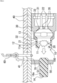
FIG. 1 is a cross-sectional view illustrating a locking tool according to a first embodiment of the present invention. -
FIG. 2 is a cross-sectional view illustrating the locking tool inFIG. 1 after operation. - Hereinafter, a locking tool according to an embodiment of the present invention will be described with reference to the drawings.
- As illustrated in
FIG. 1 , thelocking tool 100 of the present embodiment includes acylindrical member 10, anigniter 20 including a portion fitted into thecylindrical member 10, and aholder 30 that holds (locks) thecylindrical member 10 and theigniter 20 and is fixed to a part of abag holder 40. Note that thebag holder 40 is a case that accommodates and holds an airbag and a gas generator (not illustrated), and includes ahole portion 41. Thehole portion 41 is provided so that an airbag mooring member 60 (for example, a member called a tether or the like) used for adjustment of inflation of the airbag and a ring-shaped member 70 (an object to be locked) provided at a tip portion of theairbag mooring member 60 can pass therethrough. - The
cylindrical member 10 is a bottomed cylindrical member including an opening portion provided at an end portion on a side of theigniter 20, and is a component in which abottom portion 11, acylindrical portion 12, aflange portion 13, and anactuation pin 14 are integrally molded. - The
bottom portion 11 is provided with aweak portion 11a that is an annular recess at a position facing an outerperipheral portion 14a of theactuation pin 14 to be described later on an inner surface (on a side of the igniter 20). Theweak portion 11a is broken by a pressure wave received at the time of activation of theigniter 20. Note that theweak portion 11a may be anything as long as the weak portion is broken by the pressure wave received at the time of activation of theigniter 20. That is, the recess may not be a continuous annular recess, and a discontinuous recess may be formed in an annular shape. - The
actuation pin 14 is a columnar member including the outerperipheral portion 14a, and is integrally provided on an outer portion of thebottom portion 11. Furthermore, in the state (initial state) ofFIG. 1 where thelocking tool 100 is fixed to thebag holder 40, theactuation pin 14 locks theairbag mooring member 60 via the ring-shaped member 70, and a tip portion of theactuation pin 14 is inserted into ahole 51 formed in asupport piece portion 50 provided in thebag holder 40. Note that instead of using the ring-shaped member 70, an annular portion (not illustrated) may be formed by annularly forming a tip portion of theairbag mooring member 60, and the annular portion may be locked by theactuation pin 14 as an object to be locked. - The
igniter 20 includes acap member 21 that covers an ignition portion (not illustrated), and a pair ofterminal pins 22 that is connected to the ignition portion and to which a predetermined amount of current is supplied. Theigniter 20 is activated when a collision is detected by a collision detection means (not illustrated) provided in a vehicle when the vehicle collides, and the ignition portion is energized from a control unit provided in the vehicle via theterminal pins 22 based on the detection. - Furthermore, the
igniter 20 is fixed in a state where the pair ofterminal pins 22 is inserted into a pair ofhole portions 35 formed in a substantially central portion of theholder 30 in a state where a central axis of theigniter 20 and a central axis of theholder 30 substantially coincide with each other. - The
holder 30 has a substantially cylindrical shape, and is a metal integrally molded product including afemale connector portion 31, anend portion 32, and ahole portion 33. Note that theend portion 32 has a substantially cylindrical shape before theflange portion 13 is caulked and fixed, and is pressed and deformed at the time of caulking and fixing. - In the
locking tool 100 having the above-described configuration, in a case where theigniter 20 is activated, thebottom portion 11 receives a pressure wave generated from theigniter 20, so that theweak portion 11a breaks and theactuation pin 14 moves to a side of the support piece portion 50 (seeFIG. 2 ). At this time, the locking of the ring-shaped member 70 and theairbag mooring member 60 is released (seeFIG. 2 ). Then, the tip portions of the ring-shaped member 70 and theairbag mooring member 60 pass through thehole portion 41 of thebag holder 40, and the airbag (not illustrated) is released from the mooring by theairbag mooring member 60. - According to the present embodiment, since the
actuation pin 14 is integrally molded with thecylindrical member 10, it is possible to provide thelocking tool 100 capable of reducing the size and the number of parts as compared with the related art. Note that, by reducing the number of parts, the manufacturing cost can be reduced as compared with the related art. - Furthermore, according to the present embodiment, since a portion to be caulked is only the
end portion 32 of theholder 30, the size can be further reduced, and the manufacturing is easier than the related art. Therefore, the manufacturing cost can be further reduced. - Furthermore, since the annular
weak portion 11a is provided at a position facing the outerperipheral portion 14a of theactuation pin 14, in a case where theweak portion 11a breaks after the actuation, a diameter of the end portion of theactuation pin 14 on the side of theigniter 20 is substantially the same as a diameter of the outerperipheral portion 14a. As a result, when theactuation pin 14 moves toward thesupport piece portion 50, the end portion of theactuation pin 14 on the side of theigniter 20 is less likely to be caught by the ring-shaped member 70. Therefore, at the time of activation of thelocking tool 100, the ring-shaped member 70 is smoothly detached from theactuation pin 14. - Although the embodiment of the present invention has been described above with reference to the drawings, it should be understood that the specific configuration is not limited to these embodiment. The scope of the present invention is defined not by the description of the above embodiment but by the claims, and includes meanings equivalent to the claims and all modifications within the scope.
- Here, the
locking tool 100 of the above embodiment is used for locking and releasing theairbag mooring member 60 via the ring-shaped member 70, but the present invention is not limited thereto. For example, it can also be used as a locking tool that pushes a predetermined part (target object) in a fixing and opening device (selectable force limiter, load limiter, and the like) attached to one of safety devices such as an automobile called a so-called pretensioner. -
- 10
- cylindrical member
- 11
- bottom portion
- 11a
- weak portion
- 12
- cylindrical portion
- 13
- flange portion
- 14
- actuation pin
- 14a
- outer peripheral portion
- 20
- igniter
- 21
- cap member
- 22
- terminal pin
- 30
- holder
- 31
- female connector portion
- 32
- end portion
- 33, 35, 41
- hole portion
- 40
- bag holder
- 50
- support piece portion
- 51
- hole
- 60
- airbag mooring member
- 70
- ring-shaped member
- 100
- locking tool
Claims (3)
- A locking tool comprising:an igniter;a cup-shaped member including a cylindrical portion fitted into a tip portion of the igniter, a bottom portion of the cylindrical portion provided on a side of the tip portion of the igniter, and an actuation pin that is formed outside the bottom portion and locks an object to be locked; anda holder that holds the igniter and the cup-shaped member,wherein a weak portion is formed at a position facing an outer peripheral portion of the actuation pin inside the bottom portion of the cup-shaped member.
- The locking tool according to claim 1, wherein the weak portion is an annular recess.
- The locking tool according to claim 1 or 2, whereina flange portion is provided at an end portion of the cup-shaped member on a side opposite to a side of the bottom portion, andthe flange portion and the igniter are both fixed to the holder by caulking a caulking portion provided at an end portion of the holder on a side of the igniter from an outside of the flange portion.
Applications Claiming Priority (2)
| Application Number | Priority Date | Filing Date | Title |
|---|---|---|---|
| JP2022050937A JP7748319B2 (en) | 2022-03-25 | 2022-03-25 | Locking device |
| PCT/JP2023/008688 WO2023181924A1 (en) | 2022-03-25 | 2023-03-07 | Locking implement |
Publications (2)
| Publication Number | Publication Date |
|---|---|
| EP4501714A1 true EP4501714A1 (en) | 2025-02-05 |
| EP4501714A4 EP4501714A4 (en) | 2026-03-04 |
Family
ID=88101224
Family Applications (1)
| Application Number | Title | Priority Date | Filing Date |
|---|---|---|---|
| EP23774523.7A Pending EP4501714A4 (en) | 2022-03-25 | 2023-03-07 | LOCKING TOOL |
Country Status (5)
| Country | Link |
|---|---|
| US (1) | US12370973B2 (en) |
| EP (1) | EP4501714A4 (en) |
| JP (1) | JP7748319B2 (en) |
| CN (1) | CN118742466A (en) |
| WO (1) | WO2023181924A1 (en) |
Families Citing this family (1)
| Publication number | Priority date | Publication date | Assignee | Title |
|---|---|---|---|---|
| JP2024132710A (en) * | 2023-03-17 | 2024-10-01 | 豊田合成株式会社 | Cap for heat generator, heat generation structure, and air bag device |
Family Cites Families (29)
| Publication number | Priority date | Publication date | Assignee | Title |
|---|---|---|---|---|
| JP4631172B2 (en) | 2001-01-22 | 2011-02-16 | タカタ株式会社 | Airbag device |
| DE10127483B4 (en) * | 2001-06-07 | 2014-02-13 | Magna Electronics Europe Gmbh & Co.Kg | Separating screw and its use |
| US6918614B2 (en) | 2002-09-05 | 2005-07-19 | Delphi Technologies, Inc. | Inflation assembly for variable profile air bag |
| US7438313B2 (en) * | 2003-08-06 | 2008-10-21 | Arc Automotive, Inc. | Compact multi-level output gas generator |
| US7240917B2 (en) * | 2003-09-15 | 2007-07-10 | Trw Vehicle Safety Systems Inc. | Actuatable fastener |
| GB2412094A (en) * | 2004-03-17 | 2005-09-21 | Autoliv Dev | Controlled release mechanism for use with a vehicle air bag |
| US7419184B2 (en) * | 2005-06-16 | 2008-09-02 | Autoliv Asp, Inc. | Airbag tether release mechanism |
| JP2007091060A (en) | 2005-09-29 | 2007-04-12 | Toyoda Gosei Co Ltd | Inflator |
| US7114427B1 (en) * | 2005-10-19 | 2006-10-03 | Special Devices, Inc. | Quick-loosening mechanical linking device |
| US7374205B2 (en) * | 2006-02-21 | 2008-05-20 | Gm Global Technology Operations, Inc. | Air bag system |
| JP2007315533A (en) | 2006-05-26 | 2007-12-06 | Toyoda Gosei Co Ltd | Stopper |
| JP2007315504A (en) | 2006-05-26 | 2007-12-06 | Toyoda Gosei Co Ltd | Actuator with operation pin |
| US7762584B2 (en) * | 2007-09-20 | 2010-07-27 | Toyoda Gosei Co., Ltd. | Actuator which has an operating pin |
| JP4678416B2 (en) | 2008-03-21 | 2011-04-27 | トヨタ自動車株式会社 | Airbag device |
| US8191925B2 (en) * | 2008-04-14 | 2012-06-05 | Autoliv Asp, Inc. | Dynamic safety vent |
| US20090302588A1 (en) * | 2008-06-05 | 2009-12-10 | Autoliv Asp, Inc. | Systems and methods for airbag tether release |
| JP5141386B2 (en) * | 2008-06-09 | 2013-02-13 | 豊田合成株式会社 | Actuator with actuating pin |
| US7938444B2 (en) * | 2008-10-14 | 2011-05-10 | Autoliv Asp, Inc. | Mounting bracket for tether release mechanism |
| US8408584B2 (en) * | 2011-03-23 | 2013-04-02 | Autoliv Asp, Inc. | Pyrotechnic tether release assembly for inflatable airbags |
| US8353525B2 (en) * | 2011-03-23 | 2013-01-15 | Autoliv Asp, Inc. | Pyrotechnic tether release assembly with a break-away piston for inflatable airbags |
| US8408585B2 (en) * | 2011-03-23 | 2013-04-02 | Autoliv Asp, Inc. | Pyrotechnic tether release assembly for inflatable airbags |
| JP5743798B2 (en) * | 2011-08-10 | 2015-07-01 | タカタ株式会社 | Strap holding device and airbag device |
| DE102013000142B4 (en) * | 2013-01-05 | 2020-08-06 | Autoliv Development Ab | Airbag unit with influencing device |
| DE102013008149B4 (en) * | 2013-05-14 | 2024-06-06 | Zf Airbag Germany Gmbh | PYROTECHNIC DRIVE UNIT AND MANUFACTURING PROCESS |
| JP6766763B2 (en) * | 2017-06-27 | 2020-10-14 | 豊田合成株式会社 | Airbag device |
| DE102018119527A1 (en) | 2018-08-10 | 2020-02-13 | Trw Automotive Gmbh | Airbag control device and airbag device |
| JP7014104B2 (en) * | 2018-08-31 | 2022-02-01 | 豊田合成株式会社 | Airbag device |
| JP7552574B2 (en) * | 2021-12-17 | 2024-09-18 | 豊田合成株式会社 | Airbag device |
| JP7734612B2 (en) * | 2022-03-22 | 2025-09-05 | 日本化薬株式会社 | Airbag anchoring member release mechanism |
-
2022
- 2022-03-25 JP JP2022050937A patent/JP7748319B2/en active Active
-
2023
- 2023-03-07 WO PCT/JP2023/008688 patent/WO2023181924A1/en not_active Ceased
- 2023-03-07 CN CN202380022732.8A patent/CN118742466A/en active Pending
- 2023-03-07 EP EP23774523.7A patent/EP4501714A4/en active Pending
- 2023-03-07 US US18/844,440 patent/US12370973B2/en active Active
Also Published As
| Publication number | Publication date |
|---|---|
| JP2023143522A (en) | 2023-10-06 |
| US20250187559A1 (en) | 2025-06-12 |
| US12370973B2 (en) | 2025-07-29 |
| CN118742466A (en) | 2024-10-01 |
| WO2023181924A1 (en) | 2023-09-28 |
| JP7748319B2 (en) | 2025-10-02 |
| EP4501714A4 (en) | 2026-03-04 |
Similar Documents
| Publication | Publication Date | Title |
|---|---|---|
| US7726242B2 (en) | Initiator assembly | |
| US9221417B1 (en) | Releasable tether retention system | |
| US8398352B2 (en) | Separation fastener with frangible nut | |
| KR102677524B1 (en) | Initiator for a gas generator of vehicle safety device | |
| EP1870301B1 (en) | Airbag igniter | |
| US12365303B2 (en) | Restraining device and airbag module | |
| US12370973B2 (en) | Locking tool | |
| EP1555172B1 (en) | Seat belt apparatus | |
| US10259425B2 (en) | Pre-tensioner for seat belt of vehicles | |
| US7481447B2 (en) | Initiator retainer | |
| EP4497639A1 (en) | Airbag tether member release mechanism | |
| WO2019179848A1 (en) | Airbag module, steering wheel and motor vehicle | |
| EP1560732A2 (en) | Projectile firing barrel | |
| JP4148902B2 (en) | Gas generator | |
| US20040135351A1 (en) | Gas bag module | |
| US12162425B1 (en) | Initiator for a gas generator of a vehicle safety device | |
| US12330582B1 (en) | Initiator for a gas generator of a vehicle safety device | |
| US11603072B2 (en) | Dual stage inflator | |
| JP5209554B2 (en) | Pyro actuator | |
| JP7346327B2 (en) | Gas generator installation structure | |
| JP2018001981A (en) | Pretensioner and seat belt device | |
| JPH0811670A (en) | Forced activation structure of sensor for passenger protection device |
Legal Events
| Date | Code | Title | Description |
|---|---|---|---|
| STAA | Information on the status of an ep patent application or granted ep patent |
Free format text: STATUS: THE INTERNATIONAL PUBLICATION HAS BEEN MADE |
|
| PUAI | Public reference made under article 153(3) epc to a published international application that has entered the european phase |
Free format text: ORIGINAL CODE: 0009012 |
|
| STAA | Information on the status of an ep patent application or granted ep patent |
Free format text: STATUS: REQUEST FOR EXAMINATION WAS MADE |
|
| 17P | Request for examination filed |
Effective date: 20241015 |
|
| AK | Designated contracting states |
Kind code of ref document: A1 Designated state(s): AL AT BE BG CH CY CZ DE DK EE ES FI FR GB GR HR HU IE IS IT LI LT LU LV MC ME MK MT NL NO PL PT RO RS SE SI SK SM TR |
|
| DAV | Request for validation of the european patent (deleted) | ||
| DAX | Request for extension of the european patent (deleted) | ||
| A4 | Supplementary search report drawn up and despatched |
Effective date: 20260202 |
|
| RIC1 | Information provided on ipc code assigned before grant |
Ipc: B60R 21/2338 20110101AFI20260127BHEP Ipc: B01J 7/00 20060101ALI20260127BHEP Ipc: F15B 15/19 20060101ALI20260127BHEP Ipc: F42B 3/00 20060101ALI20260127BHEP |