EP4501670A1 - Torsion bar unit - Google Patents
Torsion bar unit Download PDFInfo
- Publication number
- EP4501670A1 EP4501670A1 EP23779147.0A EP23779147A EP4501670A1 EP 4501670 A1 EP4501670 A1 EP 4501670A1 EP 23779147 A EP23779147 A EP 23779147A EP 4501670 A1 EP4501670 A1 EP 4501670A1
- Authority
- EP
- European Patent Office
- Prior art keywords
- holding member
- torsion bar
- groove
- end part
- bar unit
- Prior art date
- Legal status (The legal status is an assumption and is not a legal conclusion. Google has not performed a legal analysis and makes no representation as to the accuracy of the status listed.)
- Pending
Links
Images






Classifications
-
- B—PERFORMING OPERATIONS; TRANSPORTING
- B60—VEHICLES IN GENERAL
- B60G—VEHICLE SUSPENSION ARRANGEMENTS
- B60G11/00—Resilient suspensions characterised by arrangement, location or kind of springs
- B60G11/18—Resilient suspensions characterised by arrangement, location or kind of springs having torsion-bar springs only
- B60G11/20—Resilient suspensions characterised by arrangement, location or kind of springs having torsion-bar springs only characterised by means specially adapted for attaching the spring to axle or sprung part of the vehicle
-
- F—MECHANICAL ENGINEERING; LIGHTING; HEATING; WEAPONS; BLASTING
- F16—ENGINEERING ELEMENTS AND UNITS; GENERAL MEASURES FOR PRODUCING AND MAINTAINING EFFECTIVE FUNCTIONING OF MACHINES OR INSTALLATIONS; THERMAL INSULATION IN GENERAL
- F16B—DEVICES FOR FASTENING OR SECURING CONSTRUCTIONAL ELEMENTS OR MACHINE PARTS TOGETHER, e.g. NAILS, BOLTS, CIRCLIPS, CLAMPS, CLIPS OR WEDGES; JOINTS OR JOINTING
- F16B5/00—Joining sheets or plates, e.g. panels, to one another or to strips or bars parallel to them
- F16B5/02—Joining sheets or plates, e.g. panels, to one another or to strips or bars parallel to them by means of fastening members using screw-thread
-
- F—MECHANICAL ENGINEERING; LIGHTING; HEATING; WEAPONS; BLASTING
- F16—ENGINEERING ELEMENTS AND UNITS; GENERAL MEASURES FOR PRODUCING AND MAINTAINING EFFECTIVE FUNCTIONING OF MACHINES OR INSTALLATIONS; THERMAL INSULATION IN GENERAL
- F16F—SPRINGS; SHOCK-ABSORBERS; MEANS FOR DAMPING VIBRATION
- F16F1/00—Springs
- F16F1/02—Springs made of steel or other material having low internal friction; Wound, torsion, leaf, cup, ring or the like springs, the material of the spring not being relevant
- F16F1/14—Torsion springs consisting of bars or tubes
- F16F1/16—Attachments or mountings
-
- F—MECHANICAL ENGINEERING; LIGHTING; HEATING; WEAPONS; BLASTING
- F16—ENGINEERING ELEMENTS AND UNITS; GENERAL MEASURES FOR PRODUCING AND MAINTAINING EFFECTIVE FUNCTIONING OF MACHINES OR INSTALLATIONS; THERMAL INSULATION IN GENERAL
- F16F—SPRINGS; SHOCK-ABSORBERS; MEANS FOR DAMPING VIBRATION
- F16F1/00—Springs
- F16F1/36—Springs made of rubber or other material having high internal friction, e.g. thermoplastic elastomers
-
- F—MECHANICAL ENGINEERING; LIGHTING; HEATING; WEAPONS; BLASTING
- F16—ENGINEERING ELEMENTS AND UNITS; GENERAL MEASURES FOR PRODUCING AND MAINTAINING EFFECTIVE FUNCTIONING OF MACHINES OR INSTALLATIONS; THERMAL INSULATION IN GENERAL
- F16F—SPRINGS; SHOCK-ABSORBERS; MEANS FOR DAMPING VIBRATION
- F16F1/00—Springs
- F16F1/36—Springs made of rubber or other material having high internal friction, e.g. thermoplastic elastomers
- F16F1/366—Springs made of rubber or other material having high internal friction, e.g. thermoplastic elastomers made of fibre-reinforced plastics, i.e. characterised by their special construction from such materials
-
- B—PERFORMING OPERATIONS; TRANSPORTING
- B60—VEHICLES IN GENERAL
- B60G—VEHICLE SUSPENSION ARRANGEMENTS
- B60G2204/00—Indexing codes related to suspensions per se or to auxiliary parts
- B60G2204/10—Mounting of suspension elements
- B60G2204/12—Mounting of springs or dampers
- B60G2204/122—Mounting of torsion springs
- B60G2204/1224—End mounts of stabiliser on wheel suspension
-
- B—PERFORMING OPERATIONS; TRANSPORTING
- B60—VEHICLES IN GENERAL
- B60G—VEHICLE SUSPENSION ARRANGEMENTS
- B60G2204/00—Indexing codes related to suspensions per se or to auxiliary parts
- B60G2204/61—Adjustable during maintenance
-
- B—PERFORMING OPERATIONS; TRANSPORTING
- B60—VEHICLES IN GENERAL
- B60G—VEHICLE SUSPENSION ARRANGEMENTS
- B60G2206/00—Indexing codes related to the manufacturing of suspensions: constructional features, the materials used, procedures or tools
- B60G2206/01—Constructional features of suspension elements, e.g. arms, dampers, springs
- B60G2206/012—Hollow or tubular elements
-
- B—PERFORMING OPERATIONS; TRANSPORTING
- B60—VEHICLES IN GENERAL
- B60G—VEHICLE SUSPENSION ARRANGEMENTS
- B60G2206/00—Indexing codes related to the manufacturing of suspensions: constructional features, the materials used, procedures or tools
- B60G2206/01—Constructional features of suspension elements, e.g. arms, dampers, springs
- B60G2206/40—Constructional features of dampers and/or springs
- B60G2206/42—Springs
- B60G2206/427—Stabiliser bars or tubes
-
- B—PERFORMING OPERATIONS; TRANSPORTING
- B60—VEHICLES IN GENERAL
- B60G—VEHICLE SUSPENSION ARRANGEMENTS
- B60G2206/00—Indexing codes related to the manufacturing of suspensions: constructional features, the materials used, procedures or tools
- B60G2206/01—Constructional features of suspension elements, e.g. arms, dampers, springs
- B60G2206/70—Materials used in suspensions
- B60G2206/71—Light weight materials
- B60G2206/7101—Fiber-reinforced plastics [FRP]
-
- B—PERFORMING OPERATIONS; TRANSPORTING
- B60—VEHICLES IN GENERAL
- B60G—VEHICLE SUSPENSION ARRANGEMENTS
- B60G2206/00—Indexing codes related to the manufacturing of suspensions: constructional features, the materials used, procedures or tools
- B60G2206/01—Constructional features of suspension elements, e.g. arms, dampers, springs
- B60G2206/80—Manufacturing procedures
- B60G2206/82—Joining
- B60G2206/8201—Joining by welding
-
- B—PERFORMING OPERATIONS; TRANSPORTING
- B60—VEHICLES IN GENERAL
- B60G—VEHICLE SUSPENSION ARRANGEMENTS
- B60G2206/00—Indexing codes related to the manufacturing of suspensions: constructional features, the materials used, procedures or tools
- B60G2206/01—Constructional features of suspension elements, e.g. arms, dampers, springs
- B60G2206/80—Manufacturing procedures
- B60G2206/82—Joining
- B60G2206/8207—Joining by screwing
-
- B—PERFORMING OPERATIONS; TRANSPORTING
- B60—VEHICLES IN GENERAL
- B60G—VEHICLE SUSPENSION ARRANGEMENTS
- B60G2206/00—Indexing codes related to the manufacturing of suspensions: constructional features, the materials used, procedures or tools
- B60G2206/01—Constructional features of suspension elements, e.g. arms, dampers, springs
- B60G2206/80—Manufacturing procedures
- B60G2206/82—Joining
- B60G2206/821—Joining by gluing
-
- B—PERFORMING OPERATIONS; TRANSPORTING
- B60—VEHICLES IN GENERAL
- B60G—VEHICLE SUSPENSION ARRANGEMENTS
- B60G2500/00—Indexing codes relating to the regulated action or device
- B60G2500/30—Height or ground clearance
Definitions
- An embodiment of the present invention relates to a torsion bar unit.
- the torsion bar suspension includes an arm mechanism that supports a wheel and is rotatably connected to a vehicle body, and a torsion bar spring (hereinafter, abbreviated to a torsion bar) that is connected between the arm mechanism and the vehicle body and twists and deforms in response to a swing of the arm mechanism.
- a torsion bar spring hereinafter, abbreviated to a torsion bar
- a serration formed by cutting or the like is fitted into a hole formed in a torque arm, which is a part of the arm mechanism, to fix the rotational direction.
- An object of an embodiment of the present invention is to securely fix the torsion bar without processing the FRP at the end part of the torsion bar using the FRP.
- a torsion bar unit includes a cylindrical shaped torsion bar includes a fiber-reinforced composite material extending in a first direction, a first holding member having a first groove for holding an end part of the torsion bar, and a second holding member having a second groove for holding the end part of the torsion bar at a position opposite the first groove and sandwiching and holding the end part of the torsion bar between the first groove and the second groove by overlapping the first holding member and the second holding member.
- the torsion bar unit further includes a core rod inserted into a cylindrical shaped hollow at the end part, in the above configuration.
- a corner of a tip of the core rod is rounded or tapered in a direction of insertion of the core rod into the cylindrical shaped hollow, in the above configuration.
- a shape of an end part of the torsion bar is a cylindrical polygon shape, in the above configuration.
- the cylindrical polygon shape is a square, hexagonal, or cylindrical octagon shape, in the above configuration.
- the second holding member has a through hole in a vicinity of the second groove
- the first holding member has a bolt hole in a position opposite the through hole
- the first holding member is secured to the second holding member by a bolt inserted into the through hole of the second holding member, in the above configuration.
- the second holding member has an inlay convex portion projecting from a surface opposite the first holding member in a vicinity of the second groove and a through hole passing through the inlay convex portion
- the first holding member has an inlay recess portion engaging with the inlay convex portion and a bolt hole formed on a bottom surface of the inlay recess portion and located at a position corresponding to the through hole, in the above configuration.
- the second holding member has an inlay recess portion provided on a surface opposite the first holding member in a vicinity of the second groove and a through hole passing through the inlay recess portion, and the first holding member has an inlay convex portion engaging with the inlay recess portion and a bolt hole provided in the inlay convex portion at a position corresponding to the through hole, in the above configuration.
- the first holding member is fixed to the second holding member by an adhesive material, in the above configuration.
- the first groove extends along the first direction
- a third groove is provided in the first groove
- the second groove extends along the first direction
- a fourth groove is provided in the second groove, in the above configuration.
- the first and second holding members are fixed by welding, in the above configuration.
- a thickness of an end part is thicker than a thickness of the portion of the torsion bar other than the end part, in the above configuration.
- a first holding member is integrally formed with a suspension arm, anchor arm, or torque arm, in the above configuration.
- a torsion bar unit 100 according to an embodiment of the present invention will be described with reference to FIG. 1 to FIG. 12 .
- FIG. 1 is a schematic diagram of the torsion bar unit 100 according to an embodiment of the present invention.
- FIG. 2A is an overall view of a torsion bar 110 and
- FIG. 2B is an enlarged view of an end part 112 of the torsion bar 110.
- the torsion bar unit 100 includes the torsion bar 110 and a holding member 121 and a holding member 122 that hold the torsion bar 110.
- the torsion bar unit 100 develops a spring mechanism by fixing one of the end parts 112 of the torsion bar 110 with the holding members 121 and 122 and attaching the other of the end part 112 to a torque arm or the like.
- the torsion bar 110 includes a fiber-reinforced composite material and has a cylindrical shape extending in a first direction.
- a fiber-reinforced plastic such as a carbon fiber-reinforced plastic, a glass fiber-reinforced plastic, or an aramid fiber-reinforced plastic is used as the fiber-reinforced composite material.
- Naturally occurring fibers such as CNF (cellular nanofiber), basalt fiber, or flux fiber may be used as the fiber.
- Examples of a matrix resin of the fiber-reinforced composite material include epoxy, polyurethane, and unsaturated polyester.
- a compressive strength of epoxy is 103 MPa to 173 MPa
- a compressive strength of polyurethane is 138 MPa
- unsaturated polyester is 89 MPa to 207 MPa.
- the torsion bar 110 includes a body 111 and the end part 112.
- the body 111 of the torsion bar 110 refers to parts other than the end part 112.
- the cylindrical shape of the end part 112 in the torsion bar 110 is different from the cylindrical shape of the body 111.
- the body 111 has a cylindrical shape, while the end part 112 has a cylindrical polygon shape.
- a cylindrical space also referred to as a hollow 113 is arranged between the body 111 and the end part 112.
- an inner diameter of the cylindrical polygon shape (a diameter of a cylinder) of the end part 112 is substantially the same as an inner diameter of the cylindrical shape (a diameter of a cylinder) of the body 111.
- a direction in which the torsion bar 110 extends is referred to as a first direction D1.
- the torsion bar 110 is formed by a sheet winding method or a filament winding method.
- the torsion bar 110 is formed into a cylindrical polygon shape by winding a sheet or filament-like material around a core rod for forming and compressing only the end part 112 with a mold or the like. Since the end part 112 is compressed by a mold or the like, it becomes thinner than the thickness of the body 111.
- the end part 112 of the torsion bar 110 is a part sandwiched and held by the holding member 121 and the holding member 122. Therefore, the end part 112 of the torsion bar 110 preferably has a higher compressive strength. Since the above-described material is a material having high compressive strength, it is suitable as the matrix resin of the fiber-reinforced composite material.
- a core rod 130 may be arranged in the cylindrical hollow 113 at the end part 112 of the torsion bar 110.
- materials of the core rod 130 include metals such as iron, steel, and aluminum, alloys, and hard resins.
- a compressive strength of the core rod 130 is preferably higher than a compressive strength of the matrix resin.
- a material higher than the compressive strength of the matrix resin may be appropriately selected as the material of the core rod.
- the core rod 130 is illustrated as a solid material in FIG. 2B , an embodiment of the present invention is not limited to this, and the core rod 130 may be a hollow material.
- FIG. 3A and FIG. 3B are enlarged views of the end part 112 of the torsion bar 110.
- a corner 131b of a tip 131a of the core rod 130 may be chamfered.
- the chamfering is preferably an R chamfering or a C chamfering.
- the C chamfering is a method of chamfering a pin angle into a plane at an angle of 45 degrees.
- the R chamfering is a method of chamfering a corner to be rounded. As shown in FIG.
- the corner 131b at the tip 131a of the core rod 130 is preferably a tapered shape (C chamfering).
- the corner 131b at the tip 131a of the core rod 130 is preferably a rounded shape (R-chamfering). Since the corner 131b at the tip 131a of the core rod 130 is a tapered shape or a rounded shape, when inserting the core rod 130 into the hollow 113, it becomes easier to insert the core rod 130 into the hollow 113. Alternatively, when inserting the core rod 130 into the hollow 113, it is possible to suppress the hollow 113 of the torsion bar 110 from being damaged.
- the shape of the end part 112 of the torsion bar 110 is a cylindrical polygon shape.
- a cross-sectional shape at the end part 112 along the second direction D2 perpendicular to the first direction D1 along which the torsion bar 110 extends is polygonal.
- Each cylindrical polygon corner may be chamfered.
- the chamfering is preferably the R chamfering or the C chamfering.
- the shape of the end part 112 may be a cylindrical triangular shape, a cylindrical pentagon shape, a cylindrical hexagon shape, a cylindrical heptagon shape, or a cylindrical octagon shape, or the like.
- the shape of the torsion bar 110 is preferably a cylindrical square shape, a cylindrical hexagon shape, or a cylindrical octagon shape.
- each cylindrical polygon corner may not be chamfered along the first direction D1.
- the thickness of the end part 112 refers to a diameter of an inscribed circle having a cross-sectional shape at the end part 112.
- the thickness of the body 111 refers to a diameter of a circle because the cross-sectional shape of the body 111 is circular.
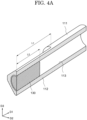
- FIG. 4A shows the case where a length L2 of the core rod 130 is shorter than a length L1 of the end part 112.
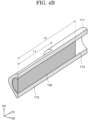
- FIG. 4B shows the case where the length L2 of the core rod 130 is longer than the length L1 of the end part 112.
- the length L2 of the core rod 130 in the first direction may be longer, shorter, or the same with respect to the length L1 of the first direction D1 of the end part 112. It may be appropriately set according to the required characteristics.
- FIG. 5 is a front view of the holding member 121 and the holding member 122.
- the holding member 121 has a groove 1212 to hold the end part 112 of the torsion bar 110 from a third direction D3.
- the holding member 122 has a groove 1222 at a position facing the groove 1212, which holds the end part 112 of the torsion bar 110 from the third direction D3.
- each of the groove 1212 and the groove 1222 extends along the first direction D1.
- a surface on which the groove 1212 is formed is referred to as a first surface 1211.
- a surface of the holding member 122 on which the groove 1222 is formed is referred to as a first surface 1221.
- Examples of the material of the holding members 121 and 122 include but are not limited to, metals such as iron, steel, and aluminum, alloys, and hard resins.
- the groove 1212 and the groove 1222 face each other to form a shape corresponding to the shape of the end part 112 of the torsion bar 110.
- the groove 1212 and the groove 1222 face each other to form a quadrangular prism.
- the shape formed by the groove 1212 and the groove 1222 is a hexagonal prism.
- the outer shape of the end part 112 may be different from the shape formed by the groove 1212 and the groove 1222 facing each other.
- the shape formed by the groove 1212 and the groove 1222 may be a diamond shape that holds only four sides of the six sides of the hexagonal prism.
- the end part 112 can be held such that the end part 112 of the torsion bar 110 is sandwiched by the groove 1212 of the holding member 121 and the groove 1222 of the holding member 122.
- the cross-sectional shape at the end part 112 is rectangular, and the direction of one of the axes of the diagonal lines of the rectangle substantially coincides with the second direction D2.
- Such a configuration does not require high processing accuracy when forming the groove 1212 and the groove 1222.
- the groove 1212 and the groove 1222 may be formed such that the direction of one of the axes of the diagonal lines of the rectangle substantially coincides with the second direction D2.
- the groove 1212 has interior walls 1212a and 1212b and a ridge 1212c sandwiched between the interior wall 1212a and the interior wall 1212b.
- the groove 1222 has an interior wall 1222a, an interior wall 1222b, and a ridge 1222c sandwiched between the interior wall 1222a and the interior wall 1222b.
- the ridges 1212c and 1222c may be rounded.
- the holding member 122 has a through hole 1223 in the vicinity of the groove 1222.
- the holding member 121 has a bolt hole (not shown in FIG. 1 ) in the vicinity of the groove 1212 at a position facing the through hole 1223.
- the through hole 1223 is arranged at four positions in the vicinity of the groove 1222.
- the bolt hole is arranged at four positions in the vicinity of the groove 1212.
- the through hole 1223 at four positions faces the bolt hole at four positions.
- the through hole arranged in the holding member 122 is not limited to four, and may be appropriately set depending on the size of the holding member 122 and the size of the groove 1222.
- the bolt hole arranged in the holding member 121 may be appropriately set depending on the position where the through hole is arranged.
- FIG. 6 is a front view of the holding member 121 and the holding member 122 in a state sandwiching the end part 112 of the torsion bar 110.
- a distance L3 is preferably arranged between the holding member 121 and the holding member 122.
- the distance L3 is also called an interference. Arranging the interference between the holding member 121 and the holding member 122 makes it possible to firmly fix the end part 112 when fixing the holding member 121 and the holding member 122 with a bolt.
- the end part 112 of the torsion bar 110 has a cylindrical polygon shape, and is sandwiched and held by the holding member 121 and the holding member 122 on which the grooves 1212 and 1222 corresponding to the cylindrical polygonal shape of the end part 112 are formed. Since the end part 112 of the torsion bar 110 can be fixed by using the holding member 121 and the holding member 122, the end part 112 does not need to be processed after the torsion bar 110 is molded in the torsion bar 110 using the FRP. Since there is no need to individually process the torque arm according to the shape of the end part 112, the manufacturing cost can be reduced.
- the end part 112 of the torsion bar 110 is configured such that the holding member 121 and the holding member 122 are fixed by a bolt, so that the end part 112 of the torsion bar 110 can be securely fixed. Furthermore, the torsion bar 110 can be easily replaced.
- the holding member 121 and the holding member 122 may be engaged by an inlay structure.
- FIG. 7 is a diagram showing the first surface 1221 of the holding member 122.
- FIG. 8 is a diagram showing the first surface 1211 of the holding member 121.
- through holes 1223a to 1223d are formed at four positions in the vicinity of the groove 1222.
- the through holes 1223a to 1223d are aligned along the groove 1222.
- Inlay convex portions 1225a and 1225b projecting from the first surface 1221 are arranged at a peripheral portion of the through holes 1223a and 1223b.
- the through holes 1223a and 1223b are arranged so as to penetrate the inlay convex portions 1225a and 1225b.
- bolt holes 1214a to 1214d corresponding to the through holes 1223a to 1223d are formed at four positions in the vicinity of the groove 1212.
- the bolt holes 1214a to 1214d are aligned along the groove 1212.
- Inlay recess portions 1215a and 1215b that engage with the inlay convex portions 1225a and 1225b are arranged at a peripheral portion of the bolt holes 1214a and 1214b.
- the bolt holes 1214a and 1214b are arranged on bottom surfaces of the inlay recess portions 1215a and 1215b.
- the inlay convex portions 1225a and 1225b projecting from the first surface 1221 are fitted into the inlay recess portions 1215a and 1215b arranged on the first surface 1211.
- the bolt is inserted into each of the through hole 1223a to the through hole 1223d to fix them.
- the holding member 121 and the holding member 122 can be firmly fixed.
- the inlay convex portions 1225a and 1225b are arranged so as not to be adjacent to each other in both the first direction D1 and the second direction D2.
- the inlay recess portions 1215a and 1215b are arranged so as not to be adjacent to each other in both the first direction D1 and the second direction D2. This improves the positioning accuracy between the holding member 121 and the holding member 122. In addition, the rigidity against relative misalignment between the holding member 121 and the holding member 122 is improved.
- inlay convex portions 1225a and 1225b are arranged so as not to be adjacent to each other in both the first direction D1 and the second direction D2
- an embodiment of the present invention is not limited to this.
- the inlay convex portions may be arranged in all of the through holes.
- a plurality of inlay convex portions may be adjacent to each other in the first direction D1 or the second direction D2.
- the inlay recess portions 1215a and 1215b are arranged so as not to be adjacent to each other in both the first direction D1 and the second direction D2 has been described in FIG. 8 , an embodiment of the present invention is not limited to this. If the inlay convex portion is arranged in all of the through holes of the holding member 122, the inlay recess portion may also be arranged in all of the bolt holes. As described above, the number of inlay convex portions and inlay recess portions may be appropriately set depending on the size of the holding member 121 and the size of the groove 1212.
- the inlay convex portions 1225a and 1225b are arranged in the holding member 122 is shown in FIG. 7 and the case where the inlay recess portions 1215a and 1215b are arranged in the holding member 121 is shown in FIG. 8 , an embodiment of the present invention is not limited to this.
- the inlay convex portions may be arranged in the holding member 121 instead of the inlay recess portions 1215a and 1215b, and the inlay recess portions may be arranged in the holding member 122 instead of the inlay convex portions 1225a and 1225b.
- the holding member 122 may have, in the vicinity of the groove 1222, an inlay recess portion arranged on a surface facing the holding member 121 and the through hole 1223 penetrating the inlay recess portion, and the holding member 121 may have a bolt hole arranged at a position corresponding to the through hole 1223 in the inlay convex portion engaged with the inlay recess portion.
- the shape of the end part 112 of the torsion bar 110 is the cylindrical quadrangular shape
- an embodiment of the present invention is not limited to this.
- the shape of the end part 112 may be a cylindrical octagon shape.
- the shape formed by the groove 1212 and the groove 1222 facing each other is an octagonal prism.
- the shape formed by the groove 1212 and the groove 1222 may be a diamond shape that holds only four sides of the eight sides of the octagonal prism.
- the cross-sectional shape of the end part 112 is octagonal, the direction of one of the axes of the diagonal lines of the octagon substantially coincides with the second direction D2.
- Such a configuration is preferable in forming the groove 1212 and the groove 1222 because high accuracy processing is not required.
- the cylindrical octagon shape is closer to the cylindrical shape than the cylindrical quadrangular shape and the cylindrical hexagon shape, the stress caused by the torsion is equalized.
- the groove 1212 and the groove 1222 may be formed such that one of the axes of the diagonal lines of the polygon coincides with the second direction D2.
- the thickness of the end part 112 of the torsion bar 110 is smaller than the thickness of the body 111
- an embodiment of the present invention is not limited to this.
- the thickness of the end part 112 may be greater than the thickness of the body 111.
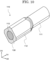
- FIG. 10 is an enlarged view of the end part 112 of the torsion bar 110.
- the diameter of the inscribed circle of the cross-sectional shape at the end part 112 may be greater than the diameter of the cross-sectional shape of the body 111 of the torsion bar 110.
- the compressive strength of the end part 112 can be improved.
- a stress-free shape may be formed at a boundary between the body 111 and the end part 112.
- the thickness of the end part 112 can be made thicker than the thickness of the body 111 by winding the sheet-like or filamentary material at the end part 112 more than the body 111.
- the shape of the end part 112 is a cylindrical quadrangular shape has been described in FIG. 10 , it is the same as the case of the cylindrical quadrangular shape even if the shape of the end part 112 is another cylindrical polygon shape.
- the holding member 121 and the holding member 122 may be fixed by an adhesive.
- the distance (interference) is not arranged between the holding member 121 and the holding member 122 in the state where the holding member 121 and the holding member 122 sandwich the end part 112 of the torsion bar 110.
- FIG. 11A is a diagram showing the first surface 1211 of the holding member 121.
- a groove 1216 is arranged at the groove 1212 of the holding member 121.
- the groove 1216 extends along a direction intersecting the direction in which the groove 1212 extends.
- the holding member 122 also has a groove extending in a direction intersecting the direction in which the groove 1222 extends.
- the groove arranged in the holding member 122 may face the groove 1216.
- the adhesive is applied to the first surface 1211 and the groove 1212 of the holding member 121, and the first surface 1221 and the groove 1222 of the holding member 122. After that, the first surface 1211 and the first surface 1221 are bonded with the end part 112 interposed therebetween, and the groove 1212, the groove 1222, and the end part 112 are bonded. In this case, the adhesive enters the groove 1216 and the groove arranged in the holding member 122. As a result, it is possible to suppress the adhesive from protruding.
- FIG. 11B is a diagram showing the first surface 1211 of the holding member 121.
- a groove 1218 extends along a direction parallel to the direction in which the groove 1212 extends.
- a groove 1219 extends along a direction parallel to the direction in which the groove 1222 extends.
- a position where the groove 1218 is arranged corresponds to the ridge 1212c shown in FIG. 5 .
- a position where the groove 1219 is arranged corresponds to the ridge 1222c shown in FIG. 5 .
- the grooves 1218 and 1219 can suppress the adhesive from protruding.
- the end part 112 may be fixed by an adhesive.
- the holding member 121 and the holding member 122 may be bonded to each other by an adhesive.
- a groove extending in a direction intersecting the direction in which the groove 1212 extends may be arranged, or a groove extending in a direction parallel to the direction in which the groove 1212 extends may be arranged.
- the holding member 122 shown in FIG. 8 a groove extending in a direction intersecting the direction in which the groove 1212 extends may be arranged, or a groove extending in a direction parallel to the direction in which the groove 1212 extends may be arranged.
- a groove extending in a direction intersecting the direction in which the groove 1222 extends may be arranged, or a groove extending in a direction parallel to the direction in which the groove 1222 extends may be arranged.
- the holding member 121 and the holding member 122 are fixed by a bolt, and the holding member 121 and the holding member 122 are firmly fixed using an adhesive.
- the groove 1216 intersecting the groove 1212 is arranged at one location is shown in FIG. 11A and FIG. 11B , it may be arranged at a plurality of places. Similarly, the groove intersecting the groove 1222 arranged in the holding member 122 may be arranged at a plurality of locations.
- the end part 112 of the torsion bar 110 may be fixed by fixing the holding member 121 and the holding member 122 by welding. In this case, there may be a distance (interference) between the holding member 121 and the holding member 122 in a state sandwiching the end part 112 of the torsion bar 110 by the holding member 121 and the holding member 122. It is preferable to perform welding while applying a load in a state where the end part 112 is sandwiched between the holding member 121 and the holding member 122.
- the through hole arranged in the holding member 121 and the bolt hole arranged in the holding member 122 can be omitted.
- the holding member 121 and the holding member 122 are fixed by welding, so that the end part 112 can be firmly fixed by the holding member 121 and the holding member 122.
- one of the holding members 121 and 122 may be integrally formed with a vehicle body, an arm, or the like.
- it may be integrally formed with a suspension arm, an anchor arm, a torque arm, or the like.
- FIG. 12 is a schematic diagram of a torsion bar unit 200. As shown in FIG. 12 , one end part 112 of the torsion bar 110 is sandwiched and held by a holding member 121A and a holding member 122A.
- the holding member 121A functions as a suspension arm.
- the holding member 122A is fixed to the holding member 121A by a bolt (not shown).
- a mechanism for sandwiching and holding the end part 112 by the holding member 121A and the holding member 122A refer to the description of the holding member 121 and the holding member 122 in FIG. 1 to FIG. 11B .
- the other end part 112 of the torsion bar 110 is sandwiched and held by a holding member 141 and a holding member 142.
- the holding member 141 and the holding member 142 are arranged on the vehicle body side.
- the holding member 142 is fixed to the holding member 141 by a bolt (not shown).
- a mechanism for sandwiching and holding the end part 112 by the holding member 141 and the holding member 142 refer to the description of the holding member 121 and the holding member 122 in FIG. 1 to FIG. 11B .
- the holding member 141 is connected to a vehicle height adjustment bolt 151.
- the vehicle height adjustment bolt 151 is connected to the vehicle body by a fixing portion 152.
- at least one of the holding members 121 and 122 and at least one of the holding members 141 and 142 are integrally formed with other components, thereby reducing the number of components.
- torsion bar units 100 and 200 described above as an embodiment of the present invention can be appropriately combined and implemented as long as no contradiction is caused. Furthermore, the addition, deletion, or design change of components as appropriate by those skilled in the art based on each embodiment of the present embodiment are also included in the scope of the present invention as long as they are provided with the gist of the present invention.
Landscapes
- Engineering & Computer Science (AREA)
- General Engineering & Computer Science (AREA)
- Mechanical Engineering (AREA)
- Springs (AREA)
- Vehicle Body Suspensions (AREA)
- Connection Of Plates (AREA)
Abstract
Description
- An embodiment of the present invention relates to a torsion bar unit.
- Conventionally, a torsion bar suspension is used as a vehicle suspension. The torsion bar suspension includes an arm mechanism that supports a wheel and is rotatably connected to a vehicle body, and a torsion bar spring (hereinafter, abbreviated to a torsion bar) that is connected between the arm mechanism and the vehicle body and twists and deforms in response to a swing of the arm mechanism.
- In the case where the torsion bar is connected to the arm mechanism, at an end part of the torsion bar, a serration formed by cutting or the like is fitted into a hole formed in a torque arm, which is a part of the arm mechanism, to fix the rotational direction.
- In addition, although a torsion bar made of steel has a disadvantage of being long and heavy, it is desired to reduce the weight of the torsion bar by using a fiber-reinforced synthetic resin (hereinafter, also referred to as FRP) (see Patent Literatures 1 and 2).
-
- Patent Literature 1:
Japanese laid-open utility model application publication No. S58-104439 - Patent Literature 2:
Japanese laid-open utility model application publication No. S58-104440 - It is difficult to form a serration at an end part of a torsion bar using an FRP due to the difficulty in processing due to the presence of fibers and the fear of a decrease in strength due to the cutting of fibers. In addition, due to variations in the material itself, it is difficult to obtain a shape precision that can be press-fitted using the FRP. Therefore, in the case where the torsion bar using the FRP is formed, a torque arm needs to be processed individually to fit the shape of the end part.
- An object of an embodiment of the present invention is to securely fix the torsion bar without processing the FRP at the end part of the torsion bar using the FRP.
- A torsion bar unit according to an embodiment of the present invention includes a cylindrical shaped torsion bar includes a fiber-reinforced composite material extending in a first direction, a first holding member having a first groove for holding an end part of the torsion bar, and a second holding member having a second groove for holding the end part of the torsion bar at a position opposite the first groove and sandwiching and holding the end part of the torsion bar between the first groove and the second groove by overlapping the first holding member and the second holding member.
- The torsion bar unit further includes a core rod inserted into a cylindrical shaped hollow at the end part, in the above configuration.
- A corner of a tip of the core rod is rounded or tapered in a direction of insertion of the core rod into the cylindrical shaped hollow, in the above configuration.
- A shape of an end part of the torsion bar is a cylindrical polygon shape, in the above configuration.
- The cylindrical polygon shape is a square, hexagonal, or cylindrical octagon shape, in the above configuration.
- The second holding member has a through hole in a vicinity of the second groove, the first holding member has a bolt hole in a position opposite the through hole, and the first holding member is secured to the second holding member by a bolt inserted into the through hole of the second holding member, in the above configuration.
- The second holding member has an inlay convex portion projecting from a surface opposite the first holding member in a vicinity of the second groove and a through hole passing through the inlay convex portion, and the first holding member has an inlay recess portion engaging with the inlay convex portion and a bolt hole formed on a bottom surface of the inlay recess portion and located at a position corresponding to the through hole, in the above configuration.
- The second holding member has an inlay recess portion provided on a surface opposite the first holding member in a vicinity of the second groove and a through hole passing through the inlay recess portion, and the first holding member has an inlay convex portion engaging with the inlay recess portion and a bolt hole provided in the inlay convex portion at a position corresponding to the through hole, in the above configuration.
- The first holding member is fixed to the second holding member by an adhesive material, in the above configuration.
- The first groove extends along the first direction, a third groove is provided in the first groove, the second groove extends along the first direction, and a fourth groove is provided in the second groove, in the above configuration.
- The first and second holding members are fixed by welding, in the above configuration.
- A thickness of an end part is thicker than a thickness of the portion of the torsion bar other than the end part, in the above configuration.
- A first holding member is integrally formed with a suspension arm, anchor arm, or torque arm, in the above configuration.
- According to an embodiment of the present invention, it is possible to securely fix a torsion bar without processing an FRP at an end part of the torsion bar using the FRP.
-
-
FIG. 1 is a schematic diagram of a torsion bar unit according to an embodiment of the present invention. -
FIG. 2A is an overall view of a torsion bar. -
FIG. 2B is an enlarged view of an end part of a torsion bar. -
FIG. 3A is an enlarged view of an end part of a torsion bar. -
FIG. 3B is an enlarged view of an end part of a torsion bar. -
FIG. 4A is an enlarged view of an end part of a torsion bar. -
FIG. 4B is an enlarged view of an end part of a torsion bar. -
FIG. 5 is a front view of two holding members. -
FIG. 6 is a front view of an end part of two holding members and a torsion bar. -
FIG. 7 is a diagram showing a first surface of a holding member. -
FIG. 8 is a diagram showing a first surface of a holding member. -
FIG. 9 is an enlarged view of an end part of a torsion bar. -
FIG. 10 is an enlarged view of an end part of a torsion bar. -
FIG. 11A is a diagram showing a first surface of a holding member. -
FIG. 11B is a diagram showing a first surface of a holding member. -
FIG. 12 is a schematic diagram of a torsion bar unit integrally formed with a torque arm. - Hereinafter, embodiments of the present invention will be described with reference to the drawings. However, the present invention can be implemented in various forms without departing from the gist thereof, and should not be construed as being limited to the description of the following exemplary embodiments.
- In the drawings, the widths, thicknesses, shapes, and the like of the respective portions may be schematically represented in comparison with the actual embodiments for clarity of explanation, but the drawings are merely examples, and do not limit the interpretation of the present invention. Furthermore, in the embodiments of the present invention, elements having the same functions as those described with respect to the above-described drawings are denoted by the same reference signs, and redundant descriptions thereof may be omitted.
- In the present specification and the like, when a plurality of the same or similar configurations is collectively represented, the same reference signs or the same reference signs added with capital letters may be represented. In describing a plurality of parts of one configuration separately, the same reference signs may be used, and hyphens and natural numbers may be further used.
- In this specification and the like, terms such as "first", "second", and "third" added to each configuration are convenient labels used to distinguish each configuration, and do not have any further meaning unless otherwise described.
- In the present embodiment, a
torsion bar unit 100 according to an embodiment of the present invention will be described with reference toFIG. 1 to FIG. 12 . -
FIG. 1 is a schematic diagram of thetorsion bar unit 100 according to an embodiment of the present invention.FIG. 2A is an overall view of atorsion bar 110 andFIG. 2B is an enlarged view of anend part 112 of thetorsion bar 110. Thetorsion bar unit 100 includes thetorsion bar 110 and a holdingmember 121 and a holdingmember 122 that hold thetorsion bar 110. Thetorsion bar unit 100 develops a spring mechanism by fixing one of theend parts 112 of thetorsion bar 110 with the holdingmembers end part 112 to a torque arm or the like. - As shown in
FIG. 2A , thetorsion bar 110 includes a fiber-reinforced composite material and has a cylindrical shape extending in a first direction. For example, a fiber-reinforced plastic such as a carbon fiber-reinforced plastic, a glass fiber-reinforced plastic, or an aramid fiber-reinforced plastic is used as the fiber-reinforced composite material. Naturally occurring fibers such as CNF (cellular nanofiber), basalt fiber, or flux fiber may be used as the fiber. Examples of a matrix resin of the fiber-reinforced composite material include epoxy, polyurethane, and unsaturated polyester. A compressive strength of epoxy is 103 MPa to 173 MPa, a compressive strength of polyurethane is 138 MPa, and unsaturated polyester is 89 MPa to 207 MPa. - The
torsion bar 110 includes abody 111 and theend part 112. In this case, thebody 111 of thetorsion bar 110 refers to parts other than theend part 112. As shown inFIG. 2B , the cylindrical shape of theend part 112 in thetorsion bar 110 is different from the cylindrical shape of thebody 111. Thebody 111 has a cylindrical shape, while theend part 112 has a cylindrical polygon shape. In thetorsion bar 110, a cylindrical space (also referred to as a hollow 113) is arranged between thebody 111 and theend part 112. That is, an inner diameter of the cylindrical polygon shape (a diameter of a cylinder) of theend part 112 is substantially the same as an inner diameter of the cylindrical shape (a diameter of a cylinder) of thebody 111. In this specification and the like, a direction in which thetorsion bar 110 extends is referred to as a first direction D1. For example, thetorsion bar 110 is formed by a sheet winding method or a filament winding method. Thetorsion bar 110 is formed into a cylindrical polygon shape by winding a sheet or filament-like material around a core rod for forming and compressing only theend part 112 with a mold or the like. Since theend part 112 is compressed by a mold or the like, it becomes thinner than the thickness of thebody 111. - The
end part 112 of thetorsion bar 110 is a part sandwiched and held by the holdingmember 121 and the holdingmember 122. Therefore, theend part 112 of thetorsion bar 110 preferably has a higher compressive strength. Since the above-described material is a material having high compressive strength, it is suitable as the matrix resin of the fiber-reinforced composite material. - In order to increase the compressive strength of the
end part 112, acore rod 130 may be arranged in the cylindrical hollow 113 at theend part 112 of thetorsion bar 110. Examples of materials of thecore rod 130 include metals such as iron, steel, and aluminum, alloys, and hard resins. A compressive strength of thecore rod 130 is preferably higher than a compressive strength of the matrix resin. A material higher than the compressive strength of the matrix resin may be appropriately selected as the material of the core rod. Although thecore rod 130 is illustrated as a solid material inFIG. 2B , an embodiment of the present invention is not limited to this, and thecore rod 130 may be a hollow material. -
FIG. 3A andFIG. 3B are enlarged views of theend part 112 of thetorsion bar 110. In a direction (the first direction D1) in which thecore rod 130 is inserted into the cylindrical hollow 113, acorner 131b of atip 131a of thecore rod 130 may be chamfered. The chamfering is preferably an R chamfering or a C chamfering. The C chamfering is a method of chamfering a pin angle into a plane at an angle of 45 degrees. The R chamfering is a method of chamfering a corner to be rounded. As shown inFIG. 3A , thecorner 131b at thetip 131a of thecore rod 130 is preferably a tapered shape (C chamfering). Alternatively, as shown inFIG. 3B , thecorner 131b at thetip 131a of thecore rod 130 is preferably a rounded shape (R-chamfering). Since thecorner 131b at thetip 131a of thecore rod 130 is a tapered shape or a rounded shape, when inserting thecore rod 130 into the hollow 113, it becomes easier to insert thecore rod 130 into the hollow 113. Alternatively, when inserting thecore rod 130 into the hollow 113, it is possible to suppress the hollow 113 of thetorsion bar 110 from being damaged. - The shape of the
end part 112 of thetorsion bar 110 is a cylindrical polygon shape. In other words, a cross-sectional shape at theend part 112 along the second direction D2 perpendicular to the first direction D1 along which thetorsion bar 110 extends is polygonal. Each cylindrical polygon corner may be chamfered. The chamfering is preferably the R chamfering or the C chamfering. Although the case where the shape of theend part 112 is a cylindrical quadrangular shape and each corner of the cylindrical quadrangular shape is chamfered will be described in the present embodiment, an embodiment of the present invention is not limited to this. For example, the shape of theend part 112 may be a cylindrical triangular shape, a cylindrical pentagon shape, a cylindrical hexagon shape, a cylindrical heptagon shape, or a cylindrical octagon shape, or the like. In view of the ease of forming theend part 112 of thetorsion bar 110, the shape of thetorsion bar 110 is preferably a cylindrical square shape, a cylindrical hexagon shape, or a cylindrical octagon shape. In addition, each cylindrical polygon corner may not be chamfered along the first direction D1. - The case where the
end part 112 of thetorsion bar 110 is thinner than thebody 111 will be described in the present embodiment. In this case, the thickness of theend part 112 refers to a diameter of an inscribed circle having a cross-sectional shape at theend part 112. In addition, the thickness of thebody 111 refers to a diameter of a circle because the cross-sectional shape of thebody 111 is circular. - Next, a length of the
core rod 130 to be inserted into theend part 112 of thetorsion bar 110 will be described with reference toFIG. 4A andFIG. 4B . -
FIG. 4A shows the case where a length L2 of thecore rod 130 is shorter than a length L1 of theend part 112.FIG. 4B shows the case where the length L2 of thecore rod 130 is longer than the length L1 of theend part 112. As illustrated, the length L2 of thecore rod 130 in the first direction may be longer, shorter, or the same with respect to the length L1 of the first direction D1 of theend part 112. It may be appropriately set according to the required characteristics. -
FIG. 5 is a front view of the holdingmember 121 and the holdingmember 122. The holdingmember 121 has agroove 1212 to hold theend part 112 of thetorsion bar 110 from a third direction D3. The holdingmember 122 has agroove 1222 at a position facing thegroove 1212, which holds theend part 112 of thetorsion bar 110 from the third direction D3. In addition, each of thegroove 1212 and thegroove 1222 extends along the first direction D1. In the holdingmember 121, a surface on which thegroove 1212 is formed is referred to as afirst surface 1211. In addition, a surface of the holdingmember 122 on which thegroove 1222 is formed is referred to as afirst surface 1221. Examples of the material of the holdingmembers - When the holding
member 121 and the holdingmember 122 are made to overlap, thegroove 1212 and thegroove 1222 face each other to form a shape corresponding to the shape of theend part 112 of thetorsion bar 110. In the present embodiment, since the outer shape of theend part 112 is a quadrangular prism, thegroove 1212 and thegroove 1222 face each other to form a quadrangular prism. For example, in the case where the outer shape of theend part 112 is a hexagonal prism, the shape formed by thegroove 1212 and thegroove 1222 is a hexagonal prism. In addition, the outer shape of theend part 112 may be different from the shape formed by thegroove 1212 and thegroove 1222 facing each other. Even if the outer shape of theend part 112 is a hexagonal prism, the shape formed by thegroove 1212 and thegroove 1222 may be a diamond shape that holds only four sides of the six sides of the hexagonal prism. Theend part 112 can be held such that theend part 112 of thetorsion bar 110 is sandwiched by thegroove 1212 of the holdingmember 121 and thegroove 1222 of the holdingmember 122. - In
FIG. 1 , the cross-sectional shape at theend part 112 is rectangular, and the direction of one of the axes of the diagonal lines of the rectangle substantially coincides with the second direction D2. Such a configuration does not require high processing accuracy when forming thegroove 1212 and thegroove 1222. Although the case where the direction of one of the axes of the diagonal lines of the rectangle substantially coincides with the second direction D2 will be described in the present embodiment, an embodiment of the present invention is not limited to this. In the case where the cross-sectional shape at theend part 112 is rectangular, thegroove 1212 and thegroove 1222 may be formed such that the direction of one of the axes of the diagonal lines of the rectangle substantially coincides with the second direction D2. - As shown in
FIG. 5 , thegroove 1212 hasinterior walls ridge 1212c sandwiched between theinterior wall 1212a and theinterior wall 1212b. Similarly, thegroove 1222 has aninterior wall 1222a, aninterior wall 1222b, and aridge 1222c sandwiched between theinterior wall 1222a and theinterior wall 1222b. Theridges - As shown in
FIG. 1 , the holdingmember 122 has a throughhole 1223 in the vicinity of thegroove 1222. The holdingmember 121 has a bolt hole (not shown inFIG. 1 ) in the vicinity of thegroove 1212 at a position facing the throughhole 1223. InFIG. 1 , the throughhole 1223 is arranged at four positions in the vicinity of thegroove 1222. In addition, the bolt hole is arranged at four positions in the vicinity of thegroove 1212. The throughhole 1223 at four positions faces the bolt hole at four positions. After theend part 112 is sandwiched between the holdingmember 121 and the holdingmember 122, the bolt is inserted into the throughhole 1223 and the bolt hole. As a result, the holdingmember 121 and the holdingmember 122 can be firmly fixed. The through hole arranged in the holdingmember 122 is not limited to four, and may be appropriately set depending on the size of the holdingmember 122 and the size of thegroove 1222. In addition, the bolt hole arranged in the holdingmember 121 may be appropriately set depending on the position where the through hole is arranged. -
FIG. 6 is a front view of the holdingmember 121 and the holdingmember 122 in a state sandwiching theend part 112 of thetorsion bar 110. As shown inFIG. 6 , a distance L3 is preferably arranged between the holdingmember 121 and the holdingmember 122. The distance L3 is also called an interference. Arranging the interference between the holdingmember 121 and the holdingmember 122 makes it possible to firmly fix theend part 112 when fixing the holdingmember 121 and the holdingmember 122 with a bolt. - Conventionally, it has been difficult to form a serration at an end part of the torsion bar using FRP due to difficulty in processing due to the presence of fibers and the fear of a decrease in strength due to the cutting of fibers. Due to variations in the material itself, it is difficult for the FRP to obtain a precise shape that can be press-fitted. Therefore, in the case where the torsion bar using the FRP is formed, a torque arm needs to be processed individually to fit the shape of the end part.
- In the
torsion bar unit 100 according to an embodiment of the present invention, theend part 112 of thetorsion bar 110 has a cylindrical polygon shape, and is sandwiched and held by the holdingmember 121 and the holdingmember 122 on which thegrooves end part 112 are formed. Since theend part 112 of thetorsion bar 110 can be fixed by using the holdingmember 121 and the holdingmember 122, theend part 112 does not need to be processed after thetorsion bar 110 is molded in thetorsion bar 110 using the FRP. Since there is no need to individually process the torque arm according to the shape of theend part 112, the manufacturing cost can be reduced. In addition, theend part 112 of thetorsion bar 110 is configured such that the holdingmember 121 and the holdingmember 122 are fixed by a bolt, so that theend part 112 of thetorsion bar 110 can be securely fixed. Furthermore, thetorsion bar 110 can be easily replaced. - Although the case where the through
hole 1223 arranged in the holdingmember 122 faces the bolt hole arranged in the holdingmember 121 has been described in the present embodiment, an embodiment of the present invention is not limited to this. The holdingmember 121 and the holdingmember 122 may be engaged by an inlay structure. -
FIG. 7 is a diagram showing thefirst surface 1221 of the holdingmember 122.FIG. 8 is a diagram showing thefirst surface 1211 of the holdingmember 121. As shown inFIG. 7 , throughholes 1223a to 1223d are formed at four positions in the vicinity of thegroove 1222. The throughholes 1223a to 1223d are aligned along thegroove 1222. Inlayconvex portions first surface 1221 are arranged at a peripheral portion of the throughholes holes convex portions - As shown in
FIG. 8 ,bolt holes 1214a to 1214d corresponding to the throughholes 1223a to 1223d are formed at four positions in the vicinity of thegroove 1212. Thebolt holes 1214a to 1214d are aligned along thegroove 1212.Inlay recess portions convex portions bolt holes bolt holes inlay recess portions member 121 and the holdingmember 122 face each other, the inlayconvex portions first surface 1221 are fitted into theinlay recess portions first surface 1211. This makes it possible to easily position the holdingmember 121 and the holdingmember 122. In this state, the bolt is inserted into each of the throughhole 1223a to the throughhole 1223d to fix them. As a result, the holdingmember 121 and the holdingmember 122 can be firmly fixed. - In
FIG. 7 , the inlayconvex portions FIG. 8 , theinlay recess portions member 121 and the holdingmember 122. In addition, the rigidity against relative misalignment between the holdingmember 121 and the holdingmember 122 is improved. - Although the case where the inlay
convex portions FIG. 7 , an embodiment of the present invention is not limited to this. The inlay convex portions may be arranged in all of the through holes. In addition, a plurality of inlay convex portions may be adjacent to each other in the first direction D1 or the second direction D2. - Although the case where the
inlay recess portions FIG. 8 , an embodiment of the present invention is not limited to this. If the inlay convex portion is arranged in all of the through holes of the holdingmember 122, the inlay recess portion may also be arranged in all of the bolt holes. As described above, the number of inlay convex portions and inlay recess portions may be appropriately set depending on the size of the holdingmember 121 and the size of thegroove 1212. - Although the case where the inlay
convex portions member 122 is shown inFIG. 7 and the case where theinlay recess portions member 121 is shown inFIG. 8 , an embodiment of the present invention is not limited to this. The inlay convex portions may be arranged in the holdingmember 121 instead of theinlay recess portions member 122 instead of the inlayconvex portions member 122 may have, in the vicinity of thegroove 1222, an inlay recess portion arranged on a surface facing the holdingmember 121 and the throughhole 1223 penetrating the inlay recess portion, and the holdingmember 121 may have a bolt hole arranged at a position corresponding to the throughhole 1223 in the inlay convex portion engaged with the inlay recess portion. - Although the case where the shape of the
end part 112 of thetorsion bar 110 is the cylindrical quadrangular shape has been described in the present embodiment, an embodiment of the present invention is not limited to this. For example, as shown inFIG. 9 , the shape of theend part 112 may be a cylindrical octagon shape. - In the case where the shape of the
end part 112 is a cylindrical octagon shape, the shape formed by thegroove 1212 and thegroove 1222 facing each other is an octagonal prism. In addition, even if the outer shape of theend part 112 is an octagonal prism, the shape formed by thegroove 1212 and thegroove 1222 may be a diamond shape that holds only four sides of the eight sides of the octagonal prism. Furthermore, if the cross-sectional shape of theend part 112 is octagonal, the direction of one of the axes of the diagonal lines of the octagon substantially coincides with the second direction D2. Such a configuration is preferable in forming thegroove 1212 and thegroove 1222 because high accuracy processing is not required. In addition, since the cylindrical octagon shape is closer to the cylindrical shape than the cylindrical quadrangular shape and the cylindrical hexagon shape, the stress caused by the torsion is equalized. - Although the case where the direction of one of the axes of the diagonal lines of the polygon substantially coincides with the second direction D2 has been described in the present embodiment, the present embodiment is not limited to this. The
groove 1212 and thegroove 1222 may be formed such that one of the axes of the diagonal lines of the polygon coincides with the second direction D2. - Although the case where the thickness of the
end part 112 of thetorsion bar 110 is smaller than the thickness of thebody 111 has been described in the present embodiment, an embodiment of the present invention is not limited to this. The thickness of theend part 112 may be greater than the thickness of thebody 111. -
FIG. 10 is an enlarged view of theend part 112 of thetorsion bar 110. For example, the diameter of the inscribed circle of the cross-sectional shape at theend part 112 may be greater than the diameter of the cross-sectional shape of thebody 111 of thetorsion bar 110. In this case, when theend part 112 is sandwiched and held by the holdingmember 121 and the holdingmember 122, the compressive strength of theend part 112 can be improved. In addition, in the case where the diameter of the inscribed circle of the cross-sectional shape at theend part 112 is larger than the diameter of the cross-sectional shape of thebody 111 of thetorsion bar 110, a stress-free shape may be formed at a boundary between thebody 111 and theend part 112. For example, it may be a shape in that the diameter of the inscribed circle of the cross-sectional shape contiguously changes at the boundary between theend part 112 and thebody 111. When forming thetorsion bar 110, the thickness of theend part 112 can be made thicker than the thickness of thebody 111 by winding the sheet-like or filamentary material at theend part 112 more than thebody 111. - Although the case where the shape of the
end part 112 is a cylindrical quadrangular shape has been described inFIG. 10 , it is the same as the case of the cylindrical quadrangular shape even if the shape of theend part 112 is another cylindrical polygon shape. - Although the method of fixing the holding
member 121 and the holdingmember 122 by the bolt has been described in the present embodiment, an embodiment of the present invention is not limited to this. The holdingmember 121 and the holdingmember 122 may be fixed by an adhesive. In this case, the distance (interference) is not arranged between the holdingmember 121 and the holdingmember 122 in the state where the holdingmember 121 and the holdingmember 122 sandwich theend part 112 of thetorsion bar 110. -
FIG. 11A is a diagram showing thefirst surface 1211 of the holdingmember 121. As shown in 11A, agroove 1216 is arranged at thegroove 1212 of the holdingmember 121. Thegroove 1216 extends along a direction intersecting the direction in which thegroove 1212 extends. Although not shown, the holdingmember 122 also has a groove extending in a direction intersecting the direction in which thegroove 1222 extends. The groove arranged in the holdingmember 122 may face thegroove 1216. - In the case where the holding
member 121 and the holdingmember 122 are fixed with an adhesive, the adhesive is applied to thefirst surface 1211 and thegroove 1212 of the holdingmember 121, and thefirst surface 1221 and thegroove 1222 of the holdingmember 122. After that, thefirst surface 1211 and thefirst surface 1221 are bonded with theend part 112 interposed therebetween, and thegroove 1212, thegroove 1222, and theend part 112 are bonded. In this case, the adhesive enters thegroove 1216 and the groove arranged in the holdingmember 122. As a result, it is possible to suppress the adhesive from protruding. -
FIG. 11B is a diagram showing thefirst surface 1211 of the holdingmember 121. As shown inFIG. 11B , agroove 1218 extends along a direction parallel to the direction in which thegroove 1212 extends. Agroove 1219 extends along a direction parallel to the direction in which thegroove 1222 extends. A position where thegroove 1218 is arranged corresponds to theridge 1212c shown inFIG. 5 . A position where thegroove 1219 is arranged corresponds to theridge 1222c shown inFIG. 5 . Thegrooves - Even when the holding
member 121 and the holdingmember 122 are fixed by a bolt, theend part 112 may be fixed by an adhesive. As shown inFIG. 7 andFIG. 8 , even when the holdingmember 121 and the holdingmember 122 constitute the inlay structure, the holdingmember 121 and the holdingmember 122 may be bonded to each other by an adhesive. For example, in the holdingmember 121 shown inFIG. 8 , a groove extending in a direction intersecting the direction in which thegroove 1212 extends may be arranged, or a groove extending in a direction parallel to the direction in which thegroove 1212 extends may be arranged. In the holdingmember 122 shown inFIG. 7 , a groove extending in a direction intersecting the direction in which thegroove 1222 extends may be arranged, or a groove extending in a direction parallel to the direction in which thegroove 1222 extends may be arranged. The holdingmember 121 and the holdingmember 122 are fixed by a bolt, and the holdingmember 121 and the holdingmember 122 are firmly fixed using an adhesive. - Although the case where the
groove 1216 intersecting thegroove 1212 is arranged at one location is shown inFIG. 11A andFIG. 11B , it may be arranged at a plurality of places. Similarly, the groove intersecting thegroove 1222 arranged in the holdingmember 122 may be arranged at a plurality of locations. - In addition, the
end part 112 of thetorsion bar 110 may be fixed by fixing the holdingmember 121 and the holdingmember 122 by welding. In this case, there may be a distance (interference) between the holdingmember 121 and the holdingmember 122 in a state sandwiching theend part 112 of thetorsion bar 110 by the holdingmember 121 and the holdingmember 122. It is preferable to perform welding while applying a load in a state where theend part 112 is sandwiched between the holdingmember 121 and the holdingmember 122. In addition, the through hole arranged in the holdingmember 121 and the bolt hole arranged in the holdingmember 122 can be omitted. The holdingmember 121 and the holdingmember 122 are fixed by welding, so that theend part 112 can be firmly fixed by the holdingmember 121 and the holdingmember 122. - Although the case where the
torsion bar unit 100 is attached to the torque arm has been described in the present embodiment, an embodiment of the present invention is not limited to this. For example, one of the holdingmembers -
FIG. 12 is a schematic diagram of atorsion bar unit 200. As shown inFIG. 12 , oneend part 112 of thetorsion bar 110 is sandwiched and held by a holdingmember 121A and a holdingmember 122A. The holdingmember 121A functions as a suspension arm. The holdingmember 122A is fixed to the holdingmember 121A by a bolt (not shown). For an explanation of a mechanism for sandwiching and holding theend part 112 by the holdingmember 121A and the holdingmember 122A, refer to the description of the holdingmember 121 and the holdingmember 122 inFIG. 1 to FIG. 11B . - The
other end part 112 of thetorsion bar 110 is sandwiched and held by a holdingmember 141 and a holdingmember 142. The holdingmember 141 and the holdingmember 142 are arranged on the vehicle body side. The holdingmember 142 is fixed to the holdingmember 141 by a bolt (not shown). For an explanation of a mechanism for sandwiching and holding theend part 112 by the holdingmember 141 and the holdingmember 142, refer to the description of the holdingmember 121 and the holdingmember 122 inFIG. 1 to FIG. 11B . The holdingmember 141 is connected to a vehicleheight adjustment bolt 151. The vehicleheight adjustment bolt 151 is connected to the vehicle body by a fixingportion 152. As shown inFIG. 12 , at least one of the holdingmembers members - The
torsion bar units - Furthermore, it is understood that, even if the effect is different from those provided by each of the above-described embodiments, the effect obvious from the description in the specification or easily predicted by persons ordinarily skilled in the art is apparently derived from the present invention.
- 100, 200: torsion bar unit, 110: torsion bar, 111: body, 112: end part, 113: hollow, 121, 122: holding member, 130: core rod, 131a: tip, 131b: corner, 141, 142: holding member, 151: vehicle height adjustment bolt, 152: fixing portion, 1211: first surface, 1212: groove, 1212a, 1212b: interior wall, 1212c: ridge, 1214a to 1214d: bolt hole, 1215a, 1215b: inlay recess portion, 1216: groove, 1221: first surface, 1222: groove, 1222a, 1222b: interior wall, 1222c: ridge, 1223: through hole, 1223a to 1223d: through hole, 1225a, 1225b: inlay convex portion
Claims (13)
- A torsion bar unit comprising:a cylindrical shaped torsion bar comprising a fiber-reinforced composite material and extending in a first direction,a first holding member having a first groove for holding an end part of the torsion bar, anda second holding member having a second groove for holding the end part of the torsion bar at a position opposite the first groove and sandwiching and holding the end part of the torsion bar between the first groove and the second groove by overlapping the first holding member and the second holding member.
- The torsion bar unit according to claim 1, further comprising:
a core rod inserted into a cylindrical shaped hollow at the end part. - The torsion bar unit according to claim 2, wherein
a corner of a tip of the core rod is rounded or tapered in a direction of insertion of the core rod into the cylindrical shaped hollow. - The torsion bar unit according to claim 1, wherein
a shape of an end part of the torsion bar is a cylindrical polygon shape. - The torsion bar unit according to claim 4, wherein
the cylindrical polygon shape is a square, hexagonal, or cylindrical octagon shape. - The torsion bar unit according to claim 1, whereinthe second holding member has a through hole in a vicinity of the second groove,the first holding member has a bolt hole in a position opposite the through hole, andthe first holding member is secured to the second holding member by a bolt inserted into the through hole of the second holding member.
- The torsion bar unit according to claim 1, whereinthe second holding member has an inlay convex portion projecting from a surface opposite the first holding member in a vicinity of the second groove and a through hole passing through the inlay convex portion, andthe first holding member has an inlay recess portion engaging with the inlay convex portion and a bolt hole formed on a bottom surface of the inlay recess portion and located at a position corresponding to the through hole.
- The torsion bar unit according to claim 1, whereinthe second holding member has an inlay recess portion provided on a surface opposite the first holding member in a vicinity of the second groove and a through hole passing through the inlay recess portion, andthe first holding member has an inlay convex portion engaging with the inlay convex portion and a bolt hole provided in the inlay convex portion at a position corresponding to the through hole.
- The torsion bar unit according to claim 1, wherein
the first holding member is fixed to the second holding member by an adhesive material. - The torsion bar unit according to claim 9, whereinthe first groove extends along the first direction,a third groove portion is provided in the first groove,the second groove extends along the first direction, anda fourth groove is provided in the second groove.
- The torsion bar unit according to claim 1, wherein
the first and second holding members are fixed by welding. - The torsion bar unit according to claim 1, wherein
a thickness of an end part is thicker than a thickness of the portion of the torsion bar other than the end part. - The torsion bar unit according to claim 1, wherein
the first holding member is integrally formed with a suspension arm, anchor arm, or torque arm.
Applications Claiming Priority (2)
| Application Number | Priority Date | Filing Date | Title |
|---|---|---|---|
| JP2022060729A JP7685969B2 (en) | 2022-03-31 | 2022-03-31 | Torsion bar unit |
| PCT/JP2023/007364 WO2023189117A1 (en) | 2022-03-31 | 2023-02-28 | Torsion bar unit |
Publications (2)
| Publication Number | Publication Date |
|---|---|
| EP4501670A1 true EP4501670A1 (en) | 2025-02-05 |
| EP4501670A4 EP4501670A4 (en) | 2025-07-30 |
Family
ID=88200616
Family Applications (1)
| Application Number | Title | Priority Date | Filing Date |
|---|---|---|---|
| EP23779147.0A Pending EP4501670A4 (en) | 2022-03-31 | 2023-02-28 | TORSION BAR UNIT |
Country Status (7)
| Country | Link |
|---|---|
| US (1) | US12427821B2 (en) |
| EP (1) | EP4501670A4 (en) |
| JP (1) | JP7685969B2 (en) |
| CN (1) | CN118871689A (en) |
| CA (1) | CA3245557A1 (en) |
| MX (1) | MX2024011619A (en) |
| WO (1) | WO2023189117A1 (en) |
Families Citing this family (1)
| Publication number | Priority date | Publication date | Assignee | Title |
|---|---|---|---|---|
| KR20250152230A (en) * | 2024-04-16 | 2025-10-23 | 현대자동차주식회사 | Tabilizer apparatus for vehicle |
Family Cites Families (34)
| Publication number | Priority date | Publication date | Assignee | Title |
|---|---|---|---|---|
| US2723870A (en) * | 1952-04-01 | 1955-11-15 | Ancel S Page | Hinged mounting for vehicle axles |
| US3175842A (en) * | 1962-04-05 | 1965-03-30 | Lubbock Machine & Supply | Crank arm axle |
| US3939779A (en) * | 1974-12-20 | 1976-02-24 | United States Steel Corporation | Railway truck assembly |
| US4131491A (en) * | 1977-12-22 | 1978-12-26 | Fmc Corporation | Torsion bar and method of forming the same |
| JPS5493517A (en) * | 1977-12-29 | 1979-07-24 | Nissan Motor Co Ltd | Car height adjusting mechanism of torsion bar system suspension |
| JPS56124506U (en) * | 1980-02-26 | 1981-09-22 | ||
| US4540197A (en) * | 1981-12-21 | 1985-09-10 | General Motors Corporation | Vehicle wheel suspension |
| JPS58104440U (en) | 1982-01-08 | 1983-07-15 | 中央発條株式会社 | torsion bar |
| JPS58104439U (en) | 1982-01-08 | 1983-07-15 | 中央発條株式会社 | torsion bar |
| JPS6117731A (en) * | 1984-07-02 | 1986-01-25 | Nhk Spring Co Ltd | Torsion bar |
| JPH01278815A (en) * | 1988-04-28 | 1989-11-09 | Mitsubishi Motors Corp | Torsion bar type suspension |
| JP3019312B2 (en) * | 1988-10-27 | 2000-03-13 | 三菱自動車工業株式会社 | Torsion bar suspension system |
| JPH0298230U (en) * | 1989-01-25 | 1990-08-06 | ||
| FR2642487B1 (en) * | 1989-01-31 | 1991-05-10 | Hutchinson | TORSION BAR BEARING |
| JPH0664424A (en) * | 1992-08-19 | 1994-03-08 | Yorozu:Kk | Suspension device for automobile |
| DE4327304C2 (en) * | 1992-08-19 | 2002-09-19 | Yorozu Jidosha Kogyo Kk | Suspension system for a motor vehicle |
| JPH09226334A (en) * | 1996-02-28 | 1997-09-02 | Mitsubishi Motors Corp | Torsion bar suspension structure |
| KR100199763B1 (en) * | 1996-12-19 | 1999-06-15 | 정몽규 | Torsion bar type suspension |
| JP3860881B2 (en) * | 1997-06-05 | 2006-12-20 | トヨタ自動車株式会社 | Torsion bar suspension |
| JP3963593B2 (en) * | 1998-04-23 | 2007-08-22 | 横浜機工株式会社 | Bar material slip prevention structure |
| US6454284B1 (en) * | 1999-07-14 | 2002-09-24 | General Motors Corporation | Torsion bar suspension with power height adjustment |
| US6431531B1 (en) * | 2001-09-26 | 2002-08-13 | Meritor Heavy Vehicle Technology, Llc | Composite torsion bar |
| US7494143B2 (en) * | 2003-04-24 | 2009-02-24 | Verbowski Larry J | Adjustable torsion bar lever |
| US7065875B2 (en) * | 2003-11-25 | 2006-06-27 | Automotive Components Holdings, Llc | Bushing support ring for stabilizer bar |
| JP4118257B2 (en) * | 2004-06-23 | 2008-07-16 | 東海ゴム工業株式会社 | Elastic support device for stabilizer bar |
| CN1875204A (en) * | 2004-12-13 | 2006-12-06 | 东洋橡胶工业株式会社 | Anti-vibration device and installation method thereof |
| US8186697B2 (en) * | 2008-01-03 | 2012-05-29 | Deere & Company | Suspension arrangement for rear castered wheels on a work machine |
| US8191911B1 (en) * | 2009-02-18 | 2012-06-05 | Norm Reynolds | Multiple torsion bar cartridge suspension systems applications |
| JP5506469B2 (en) * | 2010-03-12 | 2014-05-28 | 日野自動車株式会社 | Stabilizer bar holding structure |
| DE102010033036A1 (en) * | 2010-08-02 | 2012-02-02 | Benteler Automobiltechnik Gmbh | Process for the preparation of a stabilizer with stabilizer bearing |
| JP2014201147A (en) | 2013-04-03 | 2014-10-27 | プレス工業株式会社 | Stabilizer holding structure |
| KR101459467B1 (en) * | 2013-06-12 | 2014-11-07 | 현대자동차 주식회사 | Cab tilting device |
| DE102014223635A1 (en) * | 2014-11-19 | 2016-05-19 | Bayerische Motoren Werke Aktiengesellschaft | Stabilizer for an axle of a two-lane motor vehicle and two-lane motor vehicle with such a stabilizer |
| US12128728B1 (en) * | 2023-04-25 | 2024-10-29 | GM Global Technology Operations LLC | Suspension system with dual rate torsion bar |
-
2022
- 2022-03-31 JP JP2022060729A patent/JP7685969B2/en active Active
-
2023
- 2023-02-28 CN CN202380027345.3A patent/CN118871689A/en active Pending
- 2023-02-28 CA CA3245557A patent/CA3245557A1/en active Pending
- 2023-02-28 EP EP23779147.0A patent/EP4501670A4/en active Pending
- 2023-02-28 WO PCT/JP2023/007364 patent/WO2023189117A1/en not_active Ceased
-
2024
- 2024-09-06 US US18/826,700 patent/US12427821B2/en active Active
- 2024-09-20 MX MX2024011619A patent/MX2024011619A/en unknown
Also Published As
| Publication number | Publication date |
|---|---|
| JP2023151232A (en) | 2023-10-16 |
| US12427821B2 (en) | 2025-09-30 |
| US20240424850A1 (en) | 2024-12-26 |
| WO2023189117A1 (en) | 2023-10-05 |
| CA3245557A1 (en) | 2025-06-13 |
| JP7685969B2 (en) | 2025-05-30 |
| CN118871689A (en) | 2024-10-29 |
| MX2024011619A (en) | 2024-11-08 |
| EP4501670A4 (en) | 2025-07-30 |
Similar Documents
| Publication | Publication Date | Title |
|---|---|---|
| EP4501670A1 (en) | Torsion bar unit | |
| DE69504089T2 (en) | DAMPER BEARING HOLDING DEVICE FOR A BEARING-FREE HELICOPTER ROTOR | |
| EP4223502A1 (en) | Rod for spinal brace | |
| EP0162189B1 (en) | Frp leaf spring, especially for motor vehicles | |
| GB2049874A (en) | Bar pin for use in torque rods | |
| EP4275630B1 (en) | Rod for spinal fixture, and spinal fixture comprising same | |
| US4634399A (en) | Structural component for transmitting torque | |
| US5104251A (en) | Fitting assembly for a composite structure | |
| US3523992A (en) | Fabrication of support-module | |
| EP1666354B1 (en) | Structural component, process for manufacturing a structural component and use of a structural component for an aircraft skin | |
| US20220056975A1 (en) | Leaf spring, manufacturing process and mould of that leaf spring | |
| CA3131095A1 (en) | Joint structure and assembly method for same | |
| EP3330072B1 (en) | Textile laminate, textile laminate production method, and textile laminate production device | |
| EP3974161B1 (en) | Joint structure | |
| EP4282754B1 (en) | An attachment assembly for attachment of a tail boom to a rear fuselage of a rotorcraft | |
| JP6174377B2 (en) | Segment connection structure | |
| EP0200076A2 (en) | Beam of a plastic reinforced with a fibre material and method for its manufacture | |
| US11921461B2 (en) | Elastic retaining member for fixing a timepiece component on a support element | |
| US20210216043A1 (en) | Elastic retaining member for fixing a timepiece component on a support element | |
| JP4115702B2 (en) | Tension rod for use as a bridge cord | |
| JP6150869B2 (en) | Brace material and method for assembling brace material | |
| JP2020131915A (en) | Connection member | |
| KR20210134367A (en) | Resilient retaining members for securing the timepiece component to different support elements | |
| HK40052469B (en) | Elastic retaining member for attaching a timepiece component to a support element | |
| JPS6315737A (en) | Rod-like body made of fiber reinforced resin |
Legal Events
| Date | Code | Title | Description |
|---|---|---|---|
| STAA | Information on the status of an ep patent application or granted ep patent |
Free format text: STATUS: THE INTERNATIONAL PUBLICATION HAS BEEN MADE |
|
| PUAI | Public reference made under article 153(3) epc to a published international application that has entered the european phase |
Free format text: ORIGINAL CODE: 0009012 |
|
| STAA | Information on the status of an ep patent application or granted ep patent |
Free format text: STATUS: REQUEST FOR EXAMINATION WAS MADE |
|
| 17P | Request for examination filed |
Effective date: 20241015 |
|
| AK | Designated contracting states |
Kind code of ref document: A1 Designated state(s): AL AT BE BG CH CY CZ DE DK EE ES FI FR GB GR HR HU IE IS IT LI LT LU LV MC ME MK MT NL NO PL PT RO RS SE SI SK SM TR |
|
| REG | Reference to a national code |
Ref country code: DE Ref legal event code: R079 Free format text: PREVIOUS MAIN CLASS: B60G0021055000 Ipc: B60G0011200000 |
|
| DAV | Request for validation of the european patent (deleted) | ||
| DAX | Request for extension of the european patent (deleted) | ||
| A4 | Supplementary search report drawn up and despatched |
Effective date: 20250626 |
|
| RIC1 | Information provided on ipc code assigned before grant |
Ipc: B60G 11/20 20060101AFI20250620BHEP Ipc: B60G 21/055 20060101ALI20250620BHEP Ipc: F16B 5/02 20060101ALI20250620BHEP Ipc: B60G 11/18 20060101ALI20250620BHEP Ipc: F16F 1/16 20060101ALI20250620BHEP Ipc: F16F 1/36 20060101ALI20250620BHEP Ipc: F16F 1/366 20060101ALI20250620BHEP |