EP4501644A1 - Liquid ejection head and recording device - Google Patents
Liquid ejection head and recording device Download PDFInfo
- Publication number
- EP4501644A1 EP4501644A1 EP23780931.4A EP23780931A EP4501644A1 EP 4501644 A1 EP4501644 A1 EP 4501644A1 EP 23780931 A EP23780931 A EP 23780931A EP 4501644 A1 EP4501644 A1 EP 4501644A1
- Authority
- EP
- European Patent Office
- Prior art keywords
- liquid discharge
- channel member
- heat dissipation
- discharge head
- liquid
- Prior art date
- Legal status (The legal status is an assumption and is not a legal conclusion. Google has not performed a legal analysis and makes no representation as to the accuracy of the status listed.)
- Pending
Links
Images




Classifications
-
- B—PERFORMING OPERATIONS; TRANSPORTING
- B41—PRINTING; LINING MACHINES; TYPEWRITERS; STAMPS
- B41J—TYPEWRITERS; SELECTIVE PRINTING MECHANISMS, i.e. MECHANISMS PRINTING OTHERWISE THAN FROM A FORME; CORRECTION OF TYPOGRAPHICAL ERRORS
- B41J2/00—Typewriters or selective printing mechanisms characterised by the printing or marking process for which they are designed
- B41J2/005—Typewriters or selective printing mechanisms characterised by the printing or marking process for which they are designed characterised by bringing liquid or particles selectively into contact with a printing material
- B41J2/01—Ink jet
- B41J2/135—Nozzles
- B41J2/14—Structure thereof only for on-demand ink jet heads
- B41J2/14201—Structure of print heads with piezoelectric elements
-
- B—PERFORMING OPERATIONS; TRANSPORTING
- B41—PRINTING; LINING MACHINES; TYPEWRITERS; STAMPS
- B41J—TYPEWRITERS; SELECTIVE PRINTING MECHANISMS, i.e. MECHANISMS PRINTING OTHERWISE THAN FROM A FORME; CORRECTION OF TYPOGRAPHICAL ERRORS
- B41J2/00—Typewriters or selective printing mechanisms characterised by the printing or marking process for which they are designed
- B41J2/005—Typewriters or selective printing mechanisms characterised by the printing or marking process for which they are designed characterised by bringing liquid or particles selectively into contact with a printing material
- B41J2/01—Ink jet
- B41J2/135—Nozzles
- B41J2/14—Structure thereof only for on-demand ink jet heads
- B41J2002/14362—Assembling elements of heads
-
- B—PERFORMING OPERATIONS; TRANSPORTING
- B41—PRINTING; LINING MACHINES; TYPEWRITERS; STAMPS
- B41J—TYPEWRITERS; SELECTIVE PRINTING MECHANISMS, i.e. MECHANISMS PRINTING OTHERWISE THAN FROM A FORME; CORRECTION OF TYPOGRAPHICAL ERRORS
- B41J2202/00—Embodiments of or processes related to ink-jet or thermal heads
- B41J2202/01—Embodiments of or processes related to ink-jet heads
- B41J2202/08—Embodiments of or processes related to ink-jet heads dealing with thermal variations, e.g. cooling
-
- B—PERFORMING OPERATIONS; TRANSPORTING
- B41—PRINTING; LINING MACHINES; TYPEWRITERS; STAMPS
- B41J—TYPEWRITERS; SELECTIVE PRINTING MECHANISMS, i.e. MECHANISMS PRINTING OTHERWISE THAN FROM A FORME; CORRECTION OF TYPOGRAPHICAL ERRORS
- B41J2202/00—Embodiments of or processes related to ink-jet or thermal heads
- B41J2202/01—Embodiments of or processes related to ink-jet heads
- B41J2202/20—Modules
-
- B—PERFORMING OPERATIONS; TRANSPORTING
- B41—PRINTING; LINING MACHINES; TYPEWRITERS; STAMPS
- B41J—TYPEWRITERS; SELECTIVE PRINTING MECHANISMS, i.e. MECHANISMS PRINTING OTHERWISE THAN FROM A FORME; CORRECTION OF TYPOGRAPHICAL ERRORS
- B41J2202/00—Embodiments of or processes related to ink-jet or thermal heads
- B41J2202/01—Embodiments of or processes related to ink-jet heads
- B41J2202/21—Line printing
Definitions
- Inkjet printers and inkjet plotters utilizing an inkjet recording method are known as printing devices.
- a liquid discharge head for discharging a liquid is mounted in such a printing device that uses an inkjet method.
- liquid discharge head configured such that a heat dissipation plate is in contact with a drive IC which is a heat generation source and heat transmitted from the drive IC is released through the heat dissipation plate.
- a liquid discharge head includes a first channel member, a second channel member, a drive IC, and a heat dissipation plate.
- the first channel member is configured to discharge a liquid.
- the second channel member is configured to supply the liquid to the first channel member.
- the drive IC is configured to control discharge of the liquid.
- the heat dissipation plate is in contact with the drive IC.
- the second channel member includes a cutout portion in which the heat dissipation plate is accommodated.
- Embodiments can be appropriately combined so as not to contradict each other in terms of processing content.
- the same portions are denoted by the same reference signs, and redundant explanations are omitted.
- FIG. 1 is a front view schematically illustrating an overall front of the printer according to the embodiment.
- FIG. 2 is a plan view schematically illustrating an overall plane of the printer according to the embodiment.
- the printer according to the embodiment is, for example, a color inkjet printer.
- a printer 1 includes a paper feed roller 2, guide rollers 3, an applicator 4, a head case 5, a plurality of transport rollers 6, a plurality of frames 7, a plurality of liquid discharge heads 8, transport rollers 9, a dryer 10, transport rollers 11, a sensor 12, and a collection roller 13.
- the transport roller 6 is an example of a transporter.
- the printer 1 further includes a controller 14 configured to control each portion of the printer 1.
- the controller 14 controls operations of the paper feed roller 2, the guide rollers 3, the applicator 4, the head case 5, the plurality of transport rollers 6, the plurality of frames 7, the plurality of liquid discharge heads 8, the transport rollers 9, the dryer 10, the transport rollers 11, the sensor 12, and the collection roller 13.
- the printer 1 By depositing droplets on a printing sheet P, the printer 1 records images and characters on the printing sheet P.
- the printing sheet P is an example of a recording medium.
- the printing sheet P is rolled on the paper feed roller 2 prior to use.
- the printer 1 transports the printing sheet P from the paper feed roller 2 to the inside of the head case 5 via the guide rollers 3 and the applicator 4.
- the applicator 4 uniformly applies a coating agent over the printing sheet P. Accordingly, a surface treatment can be performed on the printing sheet P, and the printing quality of the printer 1 can thus be improved.
- the head case 5 houses the plurality of transport rollers 6, the plurality of frames 7, and the plurality of liquid discharge heads 8.
- the inside of the head case 5 is formed with a space separated from the outside except for portions connected to the outside such as portions from which the printing sheet P enters and exits the head case 5.
- the controller 14 controls at least one of controllable factors of the internal space of the head case 5, such as temperature, humidity, and air pressure, as necessary.
- the transport rollers 6 transport the printing sheet P to the vicinity of the liquid discharge heads 8 inside the head case 5.
- the frames 7 are rectangular flat plates and are positioned above and in close proximity to the printing sheet P transported by the transport rollers 6. As illustrated in FIG. 2 , the frames 7 are located such that the longitudinal direction is orthogonal to the conveyance direction of the printing sheet P.
- the plurality of frames 7 e.g., four frames are located at predetermined intervals along the conveyance direction of the printing sheet P in the head case 5.
- a liquid for example, ink
- the liquid discharge head 8 discharges the liquid supplied from the liquid tank.
- the controller 14 controls the liquid discharge heads 8 based on data of an image, characters, or the like to discharge the liquid toward the printing sheet P.
- the distance between each of the liquid discharge heads 8 and the printing sheet P is, for example, approximately 0.5 mm to 20 mm.
- the liquid discharge heads 8 are fixed to the frames 7.
- the liquid discharge heads 8 are located such that the longitudinal direction is orthogonal to the conveyance direction of the printing sheet P.
- the printer 1 according to the present embodiment is a so-called line printer in which the liquid discharge heads 8 are fixed inside the printer 1.
- the printer 1 according to the present embodiment is not limited to the line printer and may also be a so-called serial printer.
- the serial printer is a printer employing a method of alternately performing an operation of recording while moving the liquid discharge heads 8 such that the liquid discharge heads 8 reciprocate in a direction intersecting, for example, substantially orthogonal to the conveyance direction of the printing sheet P, and an operation of conveying the printing sheet P.
- FIG. 2 illustrates an example in which three liquid discharge heads 8 are located on the forward side and two liquid discharge heads 8 are located on the rear side, in the conveyance direction of the printing sheet P.
- the liquid discharge heads 8 are located such that their centers do not overlap in the conveyance direction of the printing sheet P.
- the plurality of liquid discharge heads 8 located in one frame 7 form a head group 8A.
- Four head groups 8A are located along the conveyance direction of the printing sheet P.
- the liquid discharge heads 8 belonging to the same head group 8A are supplied with four colors of ink.
- the printer 1 can perform printing with four colors of ink by using the four head groups 8A.
- the colors of the ink discharged from the respective liquid discharge heads 8 are, for example, magenta (M), yellow (Y), cyan (C), and black (K).
- the controller 14 can print a color image on the printing sheet P by controlling the respective liquid discharge heads 8 to discharge the plurality of colors of ink onto the printing sheet P.
- a coating agent may be discharged from the liquid discharge heads 8 onto the printing sheet P to perform a surface treatment on the printing sheet P.
- the number of the liquid discharge heads 8 included in one of the head groups 8A and the number of the head groups 8A mounted in the printer 1 can be changed as appropriate in accordance with an object to be printed and printing conditions.
- the number of the liquid discharge heads 8 mounted in the printer 1 may be one when it is desired to print a printable area that can be printed with one liquid discharge head 8.
- the printing sheet P on which the printing has been performed inside the head case 5 is transported to the outside of the head case 5 by the transport rollers 9 and passes through the inside of the dryer 10.
- the dryer 10 dries the printing sheet P on which the printing has been performed.
- the printing sheet P dried by the dryer 10 is transported by the transport rollers 11 and then collected by the collection roller 13.
- drying the printing sheet P with the dryer 10 helps prevent the printing sheet P taken up in an overlapped manner by the collection roller 13 from adhering to the collection roller 13 and helps prevent undried liquid from rubbing against the collection roller 13.
- the sensor 12 includes a position sensor, a speed sensor, or a temperature sensor. Based on information from the sensor 12, the controller 14 can determine the state of each part of the printer 1 and control each part of the printer 1.
- the printing sheet P is used as an object to be printed (i.e., a recording medium) is indicated, but the object to be printed in the printer 1 is not limited to the printing sheet P, and a rolled cloth or the like may be used as the object to be printed.
- the printer 1 may convey the printing sheet P put on a conveyor belt instead of directly conveying the printing sheet P.
- the printer 1 can use a sheet of paper, a cut cloth, wood, a tile, or the like as the object to be printed.
- the printer 1 may discharge a liquid containing electrically conductive particles from the liquid discharge heads 8 to print a wiring pattern or the like of an electronic device.
- the printer 1 may discharge a liquid containing a predetermined amount of a liquid chemical agent or a liquid containing the chemical agent from the liquid discharge heads 8 onto a reaction vessel or the like to produce chemicals.
- the printer 1 may also include a cleaner for cleaning the liquid discharge heads 8.
- the cleaner cleans the liquid discharge heads 8, for example, by a wiping process or a capping process.
- the wiping process is, for example, a process of wiping the surface of a portion from which a liquid is discharged, with a flexible wiper, thereby removing the liquid attached to the liquid discharge head 8.
- the capping process is performed as follows, for example. First, a cap is placed over the surface of the area to which the liquid is to be discharged (this is called capping). This creates a substantially hermetically sealed space between the surface of the area to which the liquid is to be discharged and the cap. Then, discharge of the liquid is repeated in such a hermetically sealed space. Consequently, a liquid having viscosity higher than that in a normal state, foreign matter, or the like that has clogged a nozzle 21A (see FIG. 3 ) can be removed.
- FIG. 3 is a perspective view illustrating an example of a schematic configuration of the liquid discharge head according to the first embodiment.
- FIG. 3 illustrates a three-dimensional orthogonal coordinate system including the Z-axis in which a vertically upward direction is a positive direction.
- Such an orthogonal coordinate system may also be presented in other drawings used in the description below.
- a direction in which the nozzle 21A is located in the liquid discharge head 8 that is, the negative direction side of the Z-axis may be referred to as "under” or “below”, and the positive direction side of the Z-axis may be referred to as "on” or “above” in the following description.
- the members may be omitted or illustrated in a simplified manner.
- the liquid discharge head 8 includes a first channel member 21, a second channel member 22, a pressurizer 23, a connector portion 26, a first channel 27, a second channel 28, a head cover 29, and heat dissipation plates 31, 32.
- the first channel member 21 is located on a bottom surface side of the liquid discharge head 8, which faces the printing sheet P (see FIG. 1 ).
- the first channel member 21 includes the nozzle 21A.
- the nozzle 21A opens into the bottom surface of the liquid discharge head 8 and discharges the liquid supplied to the inside of the first channel member 21 to the outside.
- the second channel member 22 is located above the first channel member 21.
- the second channel member 22 supplies the liquid to the first channel member 21.
- the second channel member 22 includes a channel 22A connecting to the nozzle 21A. The liquid is supplied from the first channel 27 to the inside of the channel 22A. Details of the second channel member 22 will be described below.
- the pressurizer 23 controls the discharge of the liquid from the first channel member 21 in accordance with a driving signal.
- the pressurizer 23 includes a piezoelectric element that is displaced by energization and a pressure chamber whose internal pressure changes in accordance with the displacement of the piezoelectric element.
- the pressurizer 23 controls the discharge of the liquid from the nozzle 21A included in the first channel member 21 to the outside by changing the internal pressure of the pressurizing chamber.
- the connector portion 26 includes a connector 24.
- the connector 24 is electrically connected to the pressurizer 23.
- the connector portion 26 externally receives, for example, a driving signal for driving the piezoelectric element included in the pressurizer 23.
- the connector portion 26 may include a connector cover 25 located between the connector 24 and the head cover 29.
- the first channel 27 supplies the liquid to the inside of the second channel member 22.
- the second channel 28 recovers the liquid from the inside of the second channel member 22.
- the liquid recovered from the second channel 28 is supplied to the first channel 27, for example, through a filter (not illustrated).
- the head cover 29 has a plate shape and is disposed to cover a space located on the opposite side of the first channel member 21 with the second channel member 22 interposed therebetween.
- the head cover 29 includes a top plate 290, first side plates 291, 292, and second side plates 293, 294, 295.
- the top plate 290 is located at an end portion on the positive direction side of the Z-axis along the XY plane.
- the first side plates 291, 292 are located at both end portions in the Y-axis direction along the ZX plane.
- the first side plate 291 is located at an end portion on the negative direction side of the Y-axis.
- the first side plate 292 is located at an end portion on the positive direction side of the Y-axis.
- One end of each of the first side plates 291, 292 is connected to the top plate 290, and the other end thereof is located above the second channel member 22.
- the second side plates 293, 294, 295 are located at both end portions in the X-axis direction along the YZ plane.
- One end of the second side plate 293 is connected to the top plate 290.
- One end of the second side plate 294 is connected to the first side plate 291.
- One end of the second side plate 295 is connected to the first side plate 292.
- the head cover 29 can be made of a conductive metal material such as aluminum.
- the head cover 29 may be made of, for example, a conductive or insulating resin material.
- heat is appropriately released from the liquid discharge head 8 via the head cover 29.
- the thermal conductivity of the head cover 29 may be higher than that of the second channel member 22. Accordingly, heat conduction from the head cover 29 to the second channel member 22 is less likely to occur. Therefore, for example, the probability of occurrence of a defect in discharge performance due to a change in properties of the liquid flowing through the second channel member 22 can be reduced.
- the head cover 29 may be in contact with the second channel member 22 or may be separated from the second channel member 22.
- the head cover 29 is located separately from the second channel member 22, and thus heat conduction from the head cover 29 to the second channel member 22 is less likely to occur, and heat conduction to the heat dissipation plates 31, 32 is promoted. Therefore, for example, the probability of occurrence of a defect in discharge performance due to a change in the properties of the liquid flowing through the second channel member 22 can be reduced.
- the heat dissipation plates 31, 32 are plate-like members located along the YZ plane.
- the heat dissipation plates 31, 32 are located to face each other in the X-axis direction with the head cover 29 interposed therebetween.
- the heat dissipation plates 31, 32 are each connected to the second side plates 293, 294, 295 of the head cover 29 via fixing members 42. For example, when the amount of heat generated by drive ICs 61, 62 is small, the heat dissipation plates 31, 32 receive heat generated inside the liquid discharge head 8 from the head cover 29 and release the heat.
- the head cover 29 receives heat generated inside the liquid discharge head 8 from the heat dissipation plates 31, 32 and releases the heat.
- the fixing members 42 may be, for example, screw members made of metal.
- the heat dissipation plates 31, 32 are screwed to the head cover 29 by these screw members, and thus the liquid discharge head 8 can ensure a heat release route.
- the fixing members 42 are an example of second members adapted to connect the heat dissipation plates 31, 32 and the head cover 29.
- the heat dissipation plates 31, 32 can be made of, for example, the same material as the head cover 29.
- the heat dissipation plates 31, 32 may be made of, for example, a material having higher thermal conductivity than the head cover 29.
- FIG. 4 is a perspective view illustrating an example of a schematic configuration of the second channel member according to the first embodiment.
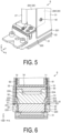
- FIG. 5 is a partially enlarged perspective view of the liquid discharge head illustrated in FIG. 3 .
- FIG. 6 is a cross-sectional view illustrating an example of the liquid discharge head according to the first embodiment.
- the second channel member 22 includes a first cutout portion 221, a second cutout portion 222, and a channel portion 224.
- the first cutout portion 221, the second cutout portion 222, and the channel portion 224 are on an upper surface (in the Z-axis positive direction) of the second channel member 22.
- the first cutout portion 221 and the second cutout portion 222 are located to cut out a side surface 220 of the second channel member 22.
- the side surface 220 is located on both end portions in the width direction of the second channel member 22 along the X axis.
- each of the heat dissipation plates 31, 32 is accommodated in a respective one of the first cutout portions 221. Accordingly, the length of the heat dissipation plates 31, 32 in the Z-axis direction can be increased compared to the head cover 29, and thus, for example, the heat dissipation of the liquid discharge head 8 can be enhanced.
- the heat dissipation plates 31, 32 are accommodated in the first cutout portion 221, and thus, for example, an increase in the size of the liquid discharge head 8 in the X-axis direction can be avoided.
- the first cutout portion 221 is located on the side surface 220, and thus, for example, the heat dissipation plates 31, 32 can be easily accommodated.
- an adhesive 41 may be located between the heat dissipation plates 31, 32 and the first cutout portion 221.
- the heat dissipation plates 31, 32 and the first cutout portion 221 may be fixed to each other with the adhesive 41.
- the adhesive 41 is an example of a first member adapted to connect the heat dissipation plates 31, 32 and the second channel member 22.
- the adhesive 41 may be, for example, a resin-based adhesive including a thermosetting resin, a photo-curable resin, or the like.
- the adhesive 41 may be made of, for example, a material having higher thermal conductivity than the fixing member 42. Therefore, for example, heat conduction from the heat dissipation plates 31, 32 to the second channel member 22 via the adhesive 41 can be reduced.
- the second cutout portion 222 is located closer to the center of the second channel member 22 than the first cutout portion 221, and is disposed to cut out the first cutout portion 221.
- the second cutout portions 222 each include an opening 223.
- flexible substrates 51, 52 are each inserted into a respective one of the openings 223.
- One end and the other end of the flexible substrate 51, 52 are electrically connected respectively to the pressurizer 23 and the connector 24.
- the drive IC (Integrated Circuit) 61 is mounted on the flexible substrate 51, and the drive IC 62 is mounted on the flexible substrate 52.
- the drive ICs 61, 62 are each a so-called integrated circuit and a heat generation source configured to generate heat when energized.
- the drive ICs 61, 62 control the pressurizer 23 in accordance with a driving signal sent from the connector 24, and controls the discharge of the liquid.
- the drive ICs 61, 62 are pressed against the heat dissipation plates 31, 32 by a pressing member 70 and elastic members 71, 72.
- the pressing member 70 is made of, for example, a metal member or a resin member, and has predetermined rigidity.
- the pressing member 70 includes portions facing the drive ICs 61, 62 with the flexible substrates 51, 52 interposed therebetween.
- the elastic members 71, 72 are located respectively between the pressing member 70 and the drive IC 61 (flexible substrate 51) and between the pressing member 70 and the drive IC 62 (flexible substrate 52).
- the drive ICs 61, 62 are pressed against the heat dissipation plates 31, 32 with appropriate pressing force by the pressing member 70 and the elastic members 71, 72.
- the drive ICs 61, 62 may be fixed to the heat dissipation plates 31, 32, for example, with an adhesive (not illustrated).
- the second channel member 22 includes the second cutout portion 222, and thus, for example, the other end side of the flexible substrates 51, 52 whose one end is connected to the pressurizer 23 is easily drawn out. Therefore, for example, the workability in assembly work of the liquid discharge head 8 is improved.
- the second channel member 22 includes the first cutout portion 221 and the second cutout portion 222, and thus, for example, a contact area between the heat dissipation plates 31, 32 and the second channel member 22 is reduced. Therefore, for example, heat conduction from the heat dissipation plates 31, 32 to the second channel member 22 can be reduced.
- the channel portion 224 is a recessed portion located at a central portion of the second channel member 22 and extends in the length direction along the Y-axis direction. As illustrated in FIG. 6 , the channel portion 224 is sealed by a lid-like member 30 located above the second channel member 22 to form the channel 22A. Note that the lid-like member 30 may be configured integrally with the second channel member 22.
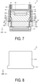
- FIG. 7 is a cross-sectional view illustrating another example of the liquid discharge head according to the first embodiment.
- an intermediate member 43 located between the heat dissipation plates 31, 32 and the second channel member 22 may be further provided.
- the intermediate member 43 may be an elastic member such as a resin sponge, which has lower thermal conductivity than the heat dissipation plates 31, 32 and the second channel member 22.
- the intermediate member 43 can serve as, for example, a buffer material and a spacer between the heat dissipation plates 31, 32 and the second channel member 22. Accordingly, heat conduction from the heat dissipation plates 31, 32 to the second channel member 22 is further less likely to occur. Therefore, for example, the probability of occurrence of a defect in discharge performance due to a change in properties of the liquid flowing through the second channel member 22 can be further reduced.
- the fact that the heat dissipation plates 31, 32 are located separately from the second channel member 22 means that the heat dissipation plates 31, 32 are not in direct contact with the second channel member 22.
- another member may be interposed between the heat dissipation plates 31, 32 and the second channel member 22 as illustrated in FIG. 7 , or the heat dissipation plates 31, 32 and the second channel member 22 may be separated without another member interposed therebetween.
- FIG. 8 is a plan view illustrating an example of a schematic configuration of the heat dissipation plate included in the liquid discharge head according to the second embodiment.
- the heat dissipation plate 31 may include a first portion 311 and a second portion 312.
- the first portion 311 is located closer to the negative direction side of the Z-axis than the second portion 312.
- the length of the first portion 311 along the Y-axis direction is larger than that of the second portion 312.
- the first portion 311 of the heat dissipation plate 31 is a first wide portion whose width in the longitudinal direction of the liquid discharge head 8 is larger than other portions.
- the heat dissipation plate 31 has the first portion 311, and thus, for example, the heat capacity of the heat dissipation plate 31 can be improved, and the heat dissipation of the liquid discharge head 8 is improved.
- FIG. 9 is a partially enlarged perspective view illustrating an example of a schematic configuration of the liquid discharge head according to the second embodiment. As illustrated in FIG. 9 , the first portion 311 that is the first wide portion of the heat dissipation plate 31 may be accommodated in the first cutout portion 221.
- the first portion 311 is accommodated in the first cutout portion 221 as just described, and thus, for example, the heat capacity can be improved without increasing the size of the heat dissipation plate 31 and/or the liquid discharge head 8 in the height direction (Z-axis direction), and the heat dissipation of the liquid discharge head 8 is improved.
- the heat dissipation plate 31 is fixed to the second channel member 22 with an adhesive, the adhesive can remain on an upper surface of the protruding first portion 311, and thus workability is improved.
- the heat dissipation plate 32 can be configured in the same manner as the heat dissipation plate 31.
- FIG. 10 is a plan view illustrating an example of a schematic configuration of the heat dissipation plate and a thermal insulating member that are included in the liquid discharge head according to the third embodiment.
- FIG. 11 is a partially enlarged perspective view illustrating an example of a schematic configuration of the liquid discharge head according to the third embodiment.
- the liquid discharge head 8 according to the present embodiment is different from the liquid discharge head 8 according to each of the embodiments described above in that the liquid discharge head 8 further includes a thermal insulating member 80 located between the heat dissipation plate 31 and the first channel member 21. Therefore, heat conduction from the heat dissipation plate 31 to the first channel member 21 can be further reduced.
- the thermal insulating member 80 is made of, for example, an epoxide-based resin.
- the thermal conductivity of the thermal insulating member 80 may be lower than the thermal conductivity of the heat dissipation plate 31.
- the thermal conductivity of the thermal insulating member 80 is, for example, 0.19 (W/m°C).
- the heat dissipation plate 31 may include a third portion 313 and a fourth portion 314.
- the third portion 313 is located closer to the negative direction side of the Z-axis than the fourth portion 314.
- the length of the third portion 313 along the Y-axis direction is smaller than that of the fourth portion 314.
- the thermal insulating member 80 may include a first portion 801, a second portion 802, and a third portion 803.
- the second portion 802 and the third portion 803 are located at both ends in the Y-axis direction.
- the third portion 313 of the heat dissipation plate 31 is accommodated between the second portion 802 and the third portion 803.
- the first portion 801 is located closer to the negative direction side of the Z-axis than the second portion 802 and the third portion 803.
- the length of the first portion 801 along the Y-axis direction is larger than those of the second portion 802 and the third portion 803.
- the first portion 801 of the thermal insulating member 80 is a second wide portion whose width in the longitudinal direction of the liquid discharge head 8 is larger than other portions.
- the heat dissipation plate 31 includes the first portion 801, and thus, for example, the bonding area between the heat dissipation plate 31 and the second channel member 22 can be increased, and the bonding strength is improved.
- the first portion 801 that is the second wide portion of the thermal insulating member 80 may be accommodated in the first cutout portion 221.
- the first portion 801 of the thermal insulating member 80 is accommodated in the first cutout portion 221 to be bonded to the second channel member 22, and thus, for example, the liquid discharge head 8 compact in outer appearance can be obtained.
- the adhesive can remain on an upper surface of the protruding first portion 801, and thus workability is improved.
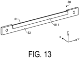
- FIGs. 12 and 13 are each a perspective view illustrating an example of the thermal insulating member included in the liquid discharge head according to the third embodiment.
- the thermal insulating member 80 is an elongated member extending in the longitudinal direction (Y-axis direction) of the liquid discharge head 8.
- the thermal insulating member 80 includes a first portion 81, a second portion 82, and a third portion 83 connecting the first portion 81 and the second portion 82.
- the thermal insulating member 80 has a substantially S-shape in a cross-sectional view.
- the first portion 81 and the second portion 82 are located to be shifted from each other in the X-axis direction.
- the first portion 81 has a surface 811 facing the inside of the liquid discharge head 8.
- the second portion 82 has a surface 821 facing the outside of the liquid discharge head 8.
- the third portion 53 connects a lower portion of the first portion 81 and an upper portion of the second portion 82 and accommodates the third portion 313 of the heat dissipation plate 31.
- the thermal insulating member 80 may include protruding portions 84 protruding from the first portion 81 toward the outside of the liquid discharge head 8.
- the protruding portions 84 are accommodated in through holes 315 (see FIG. 11 ) included in the heat dissipation plate 31, and thus a relative position shift between the heat dissipation plate 31 and the thermal insulating member 80 is less likely to occur.
- the heat dissipation plate 31 may include recessed portions in which the protruding portions 84 can be accommodated.
- the heat dissipation plate 32 and a thermal insulating member located near the heat dissipation plate 32 can be configured in the same manner as the heat dissipation plate 31 and the thermal insulating member 80.
- the heat dissipation plates 31, 32 are each connected to the second side plates 293, 294, 295 of the head cover 29 via the fixing members 42.
- the adhesive 41 may be located between the heat dissipation plates 31, 32 and the second side plates 293, 294, 295, and the heat dissipation plates 31, 32 and the second side plates 293, 294, 295 may be connected with the use of the adhesive 41 and the fixing members 42.
- the heat dissipation plates 31, 32 and the head cover 29 can be more firmly fixed to each other.
- the second side plates 293, 294, 295 of the head cover 29 are located independently as described in the aforementioned embodiments; however, two or more of the second side plates 293 to 295 may be located to be continuous with each other.
- the liquid discharge head 8 includes the heat dissipation plates 31, 32 as described in the aforementioned embodiments, but may include only one of the heat dissipation plates 31, 32.
- the second channel member 22 may include only the first cutout portion 221 corresponding to the heat dissipation plate included in the liquid discharge head 8.
- the liquid discharge head 8 includes the first channel member 21, the second channel member 22, the drive ICs 61, 62, and the heat dissipation plates 31, 32.
- the first channel member 21 is configured to discharge a liquid.
- the second channel member 22 supplies the liquid to the first channel member 21.
- the drive ICs 61, 62 are configured to control the discharge of the liquid.
- the heat dissipation plates 31, 32 are respectively in contact with the drive ICs 61, 62.
- the second channel member 22 includes the cutout portion (first cutout portion 221) in which the heat dissipation plates 31, 32 are accommodated.
Landscapes
- Ink Jet (AREA)
Abstract
Description
- The disclosed embodiments relate to a liquid discharge head and a recording device.
- Inkjet printers and inkjet plotters utilizing an inkjet recording method are known as printing devices. A liquid discharge head for discharging a liquid is mounted in such a printing device that uses an inkjet method.
- An example of such a liquid discharge head is a known liquid discharge head configured such that a heat dissipation plate is in contact with a drive IC which is a heat generation source and heat transmitted from the drive IC is released through the heat dissipation plate.
-
- Patent Document 1:
JP 2014-97661 A - Patent Document 2:
JP 2008-87231 A - A liquid discharge head according to an aspect of an embodiment includes a first channel member, a second channel member, a drive IC, and a heat dissipation plate. The first channel member is configured to discharge a liquid. The second channel member is configured to supply the liquid to the first channel member. The drive IC is configured to control discharge of the liquid. The heat dissipation plate is in contact with the drive IC. The second channel member includes a cutout portion in which the heat dissipation plate is accommodated.
-
-
FIG. 1 is a front view schematically illustrating an overall front of a printer according to an embodiment. -
FIG. 2 is a plan view schematically illustrating an overall plane of the printer according to the embodiment. -
FIG. 3 is a perspective view illustrating an example of a schematic configuration of a liquid discharge head according to a first embodiment. -
FIG. 4 is a perspective view illustrating an example of a schematic configuration of a second channel member according to the first embodiment. -
FIG. 5 is a partially enlarged perspective view of the liquid discharge head illustrated inFIG. 3 . -
FIG. 6 is a cross-sectional view illustrating an example of the liquid discharge head according to the first embodiment. -
FIG. 7 is a cross-sectional view illustrating another example of the liquid discharge head according to the first embodiment. -
FIG. 8 is a plan view illustrating an example of a schematic configuration of a heat dissipation plate included in the liquid discharge head according to a second embodiment. -
FIG. 9 is a partially enlarged perspective view illustrating an example of a schematic configuration of the liquid discharge head according to the second embodiment. -
FIG. 10 is a plan view illustrating an example of a schematic configuration of the heat dissipation plate and a thermal insulating member that are included in the liquid discharge head according to a third embodiment. -
FIG. 11 is a partially enlarged perspective view illustrating an example of a schematic configuration of the liquid discharge head according to the third embodiment. -
FIG. 12 is a perspective view illustrating an example of the thermal insulating member included in the liquid discharge head according to the third embodiment. -
FIG. 13 is a perspective view illustrating an example of the thermal insulating member included in the liquid discharge head according to the third embodiment. - In the liquid discharge head described above, there is room for further improvement in terms of heat dissipation.
- Therefore, provision of a liquid discharge head and a recording device that provide enhanced heat dissipation is expected.
- Embodiments of a liquid discharge head and a recording device disclosed in the present application will be described below with reference to the accompanying drawings. Note that the present disclosure is not limited by the following embodiments. Note that the drawings are schematic and that the dimensional relationships between elements, the proportions of the elements, and the like may differ from the actual ones. There may be differences between the drawings in terms of dimensional relationships, proportions, and the like.
- In the following embodiments, expressions such as "constant", "orthogonal", "perpendicular", and "parallel" may be used, but these expressions do not necessarily have to strictly mean "constant", "orthogonal", "perpendicular", and "parallel". In other words, it is assumed that the above expressions allow for deviations in manufacturing accuracy, installation accuracy, or the like.
- Embodiments can be appropriately combined so as not to contradict each other in terms of processing content. In the following embodiments, the same portions are denoted by the same reference signs, and redundant explanations are omitted.
- With reference to
FIGs. 1 and 2 , an overview of a printer is described as an example of a recording device according to an embodiment.FIG. 1 is a front view schematically illustrating an overall front of the printer according to the embodiment.FIG. 2 is a plan view schematically illustrating an overall plane of the printer according to the embodiment. The printer according to the embodiment is, for example, a color inkjet printer. - As illustrated in
FIG. 1 , a printer 1 includes apaper feed roller 2,guide rollers 3, anapplicator 4, ahead case 5, a plurality oftransport rollers 6, a plurality offrames 7, a plurality ofliquid discharge heads 8,transport rollers 9, adryer 10,transport rollers 11, asensor 12, and acollection roller 13. Thetransport roller 6 is an example of a transporter. - The printer 1 further includes a
controller 14 configured to control each portion of the printer 1. Thecontroller 14 controls operations of thepaper feed roller 2, theguide rollers 3, theapplicator 4, thehead case 5, the plurality oftransport rollers 6, the plurality offrames 7, the plurality ofliquid discharge heads 8, thetransport rollers 9, thedryer 10, thetransport rollers 11, thesensor 12, and thecollection roller 13. - By depositing droplets on a printing sheet P, the printer 1 records images and characters on the printing sheet P. The printing sheet P is an example of a recording medium. The printing sheet P is rolled on the
paper feed roller 2 prior to use. The printer 1 transports the printing sheet P from thepaper feed roller 2 to the inside of thehead case 5 via theguide rollers 3 and theapplicator 4. - The
applicator 4 uniformly applies a coating agent over the printing sheet P. Accordingly, a surface treatment can be performed on the printing sheet P, and the printing quality of the printer 1 can thus be improved. - The
head case 5 houses the plurality oftransport rollers 6, the plurality offrames 7, and the plurality ofliquid discharge heads 8. The inside of thehead case 5 is formed with a space separated from the outside except for portions connected to the outside such as portions from which the printing sheet P enters and exits thehead case 5. - The
controller 14 controls at least one of controllable factors of the internal space of thehead case 5, such as temperature, humidity, and air pressure, as necessary. Thetransport rollers 6 transport the printing sheet P to the vicinity of theliquid discharge heads 8 inside thehead case 5. - The
frames 7 are rectangular flat plates and are positioned above and in close proximity to the printing sheet P transported by thetransport rollers 6. As illustrated inFIG. 2 , theframes 7 are located such that the longitudinal direction is orthogonal to the conveyance direction of the printing sheet P. The plurality of frames 7 (e.g., four frames) are located at predetermined intervals along the conveyance direction of the printing sheet P in thehead case 5. - A liquid, for example, ink, is supplied to the
liquid discharge head 8 from a liquid tank (not illustrated). Theliquid discharge head 8 discharges the liquid supplied from the liquid tank. - The
controller 14 controls theliquid discharge heads 8 based on data of an image, characters, or the like to discharge the liquid toward the printing sheet P. The distance between each of the liquid discharge heads 8 and the printing sheet P is, for example, approximately 0.5 mm to 20 mm. - The liquid discharge heads 8 are fixed to the
frames 7. The liquid discharge heads 8 are located such that the longitudinal direction is orthogonal to the conveyance direction of the printing sheet P. - In other words, the printer 1 according to the present embodiment is a so-called line printer in which the liquid discharge heads 8 are fixed inside the printer 1. Note that the printer 1 according to the present embodiment is not limited to the line printer and may also be a so-called serial printer.
- The serial printer is a printer employing a method of alternately performing an operation of recording while moving the liquid discharge heads 8 such that the liquid discharge heads 8 reciprocate in a direction intersecting, for example, substantially orthogonal to the conveyance direction of the printing sheet P, and an operation of conveying the printing sheet P.
- As illustrated in
FIG. 2 , a plurality of liquid discharge heads 8 (e.g., five liquid discharge heads) are fixed to oneframe 7.FIG. 2 illustrates an example in which three liquid discharge heads 8 are located on the forward side and two liquid discharge heads 8 are located on the rear side, in the conveyance direction of the printing sheet P. The liquid discharge heads 8 are located such that their centers do not overlap in the conveyance direction of the printing sheet P. - The plurality of liquid discharge heads 8 located in one
frame 7 form ahead group 8A. Fourhead groups 8A are located along the conveyance direction of the printing sheet P. The liquid discharge heads 8 belonging to thesame head group 8A are supplied with four colors of ink. As a result, the printer 1 can perform printing with four colors of ink by using the fourhead groups 8A. - The colors of the ink discharged from the respective liquid discharge heads 8 are, for example, magenta (M), yellow (Y), cyan (C), and black (K). The
controller 14 can print a color image on the printing sheet P by controlling the respective liquid discharge heads 8 to discharge the plurality of colors of ink onto the printing sheet P. - Note that a coating agent may be discharged from the liquid discharge heads 8 onto the printing sheet P to perform a surface treatment on the printing sheet P.
- The number of the liquid discharge heads 8 included in one of the
head groups 8A and the number of thehead groups 8A mounted in the printer 1 can be changed as appropriate in accordance with an object to be printed and printing conditions. For example, the number of the liquid discharge heads 8 mounted in the printer 1 may be one when it is desired to print a printable area that can be printed with oneliquid discharge head 8. - The printing sheet P on which the printing has been performed inside the
head case 5 is transported to the outside of thehead case 5 by thetransport rollers 9 and passes through the inside of thedryer 10. Thedryer 10 dries the printing sheet P on which the printing has been performed. The printing sheet P dried by thedryer 10 is transported by thetransport rollers 11 and then collected by thecollection roller 13. - In the printer 1, drying the printing sheet P with the
dryer 10 helps prevent the printing sheet P taken up in an overlapped manner by thecollection roller 13 from adhering to thecollection roller 13 and helps prevent undried liquid from rubbing against thecollection roller 13. - The
sensor 12 includes a position sensor, a speed sensor, or a temperature sensor. Based on information from thesensor 12, thecontroller 14 can determine the state of each part of the printer 1 and control each part of the printer 1. - In the printer 1 described above, a case where the printing sheet P is used as an object to be printed (i.e., a recording medium) is indicated, but the object to be printed in the printer 1 is not limited to the printing sheet P, and a rolled cloth or the like may be used as the object to be printed.
- The printer 1 may convey the printing sheet P put on a conveyor belt instead of directly conveying the printing sheet P. By using the conveyor belt, the printer 1 can use a sheet of paper, a cut cloth, wood, a tile, or the like as the object to be printed.
- The printer 1 may discharge a liquid containing electrically conductive particles from the liquid discharge heads 8 to print a wiring pattern or the like of an electronic device. The printer 1 may discharge a liquid containing a predetermined amount of a liquid chemical agent or a liquid containing the chemical agent from the liquid discharge heads 8 onto a reaction vessel or the like to produce chemicals.
- The printer 1 may also include a cleaner for cleaning the liquid discharge heads 8. The cleaner cleans the liquid discharge heads 8, for example, by a wiping process or a capping process.
- The wiping process is, for example, a process of wiping the surface of a portion from which a liquid is discharged, with a flexible wiper, thereby removing the liquid attached to the
liquid discharge head 8. - The capping process is performed as follows, for example. First, a cap is placed over the surface of the area to which the liquid is to be discharged (this is called capping). This creates a substantially hermetically sealed space between the surface of the area to which the liquid is to be discharged and the cap. Then, discharge of the liquid is repeated in such a hermetically sealed space. Consequently, a liquid having viscosity higher than that in a normal state, foreign matter, or the like that has clogged a
nozzle 21A (seeFIG. 3 ) can be removed. - The configuration of the
liquid discharge head 8 according to a first embodiment will be described with reference toFIGs. 3 to 6 .FIG. 3 is a perspective view illustrating an example of a schematic configuration of the liquid discharge head according to the first embodiment. - For the sake of clarity,
FIG. 3 illustrates a three-dimensional orthogonal coordinate system including the Z-axis in which a vertically upward direction is a positive direction. Such an orthogonal coordinate system may also be presented in other drawings used in the description below. For the sake of convenience, a direction in which thenozzle 21A is located in theliquid discharge head 8, that is, the negative direction side of the Z-axis may be referred to as "under" or "below", and the positive direction side of the Z-axis may be referred to as "on" or "above" in the following description. InFIGs. 3 to 6 , the members may be omitted or illustrated in a simplified manner. - As illustrated in
FIG. 3 , theliquid discharge head 8 includes afirst channel member 21, asecond channel member 22, apressurizer 23, aconnector portion 26, afirst channel 27, asecond channel 28, ahead cover 29, andheat dissipation plates - The
first channel member 21 is located on a bottom surface side of theliquid discharge head 8, which faces the printing sheet P (seeFIG. 1 ). Thefirst channel member 21 includes thenozzle 21A. Thenozzle 21A opens into the bottom surface of theliquid discharge head 8 and discharges the liquid supplied to the inside of thefirst channel member 21 to the outside. - The
second channel member 22 is located above thefirst channel member 21. Thesecond channel member 22 supplies the liquid to thefirst channel member 21. Thesecond channel member 22 includes achannel 22A connecting to thenozzle 21A. The liquid is supplied from thefirst channel 27 to the inside of thechannel 22A. Details of thesecond channel member 22 will be described below. - The pressurizer 23 controls the discharge of the liquid from the
first channel member 21 in accordance with a driving signal. Thepressurizer 23 includes a piezoelectric element that is displaced by energization and a pressure chamber whose internal pressure changes in accordance with the displacement of the piezoelectric element. The pressurizer 23 controls the discharge of the liquid from thenozzle 21A included in thefirst channel member 21 to the outside by changing the internal pressure of the pressurizing chamber. - The
connector portion 26 includes aconnector 24. Theconnector 24 is electrically connected to thepressurizer 23. In response to a control signal output from the controller 14 (seeFIG. 1 ), theconnector portion 26 externally receives, for example, a driving signal for driving the piezoelectric element included in thepressurizer 23. Theconnector portion 26 may include aconnector cover 25 located between theconnector 24 and thehead cover 29. - The
first channel 27 supplies the liquid to the inside of thesecond channel member 22. Thesecond channel 28 recovers the liquid from the inside of thesecond channel member 22. The liquid recovered from thesecond channel 28 is supplied to thefirst channel 27, for example, through a filter (not illustrated). - The
head cover 29 has a plate shape and is disposed to cover a space located on the opposite side of thefirst channel member 21 with thesecond channel member 22 interposed therebetween. Thehead cover 29 includes atop plate 290,first side plates 291, 292, andsecond side plates - The
top plate 290 is located at an end portion on the positive direction side of the Z-axis along the XY plane. Thefirst side plates 291, 292 are located at both end portions in the Y-axis direction along the ZX plane. Thefirst side plate 291 is located at an end portion on the negative direction side of the Y-axis. The first side plate 292 is located at an end portion on the positive direction side of the Y-axis. One end of each of thefirst side plates 291, 292 is connected to thetop plate 290, and the other end thereof is located above thesecond channel member 22. - The
second side plates second side plate 293 is connected to thetop plate 290. One end of thesecond side plate 294 is connected to thefirst side plate 291. One end of thesecond side plate 295 is connected to the first side plate 292. - The head cover 29 can be made of a conductive metal material such as aluminum. The
head cover 29 may be made of, for example, a conductive or insulating resin material. Thus, heat is appropriately released from theliquid discharge head 8 via thehead cover 29. The thermal conductivity of thehead cover 29 may be higher than that of thesecond channel member 22. Accordingly, heat conduction from thehead cover 29 to thesecond channel member 22 is less likely to occur. Therefore, for example, the probability of occurrence of a defect in discharge performance due to a change in properties of the liquid flowing through thesecond channel member 22 can be reduced. - The
head cover 29 may be in contact with thesecond channel member 22 or may be separated from thesecond channel member 22. Thehead cover 29 is located separately from thesecond channel member 22, and thus heat conduction from thehead cover 29 to thesecond channel member 22 is less likely to occur, and heat conduction to theheat dissipation plates second channel member 22 can be reduced. - The
heat dissipation plates heat dissipation plates head cover 29 interposed therebetween. Theheat dissipation plates second side plates head cover 29 via fixingmembers 42. For example, when the amount of heat generated bydrive ICs heat dissipation plates liquid discharge head 8 from thehead cover 29 and release the heat. For example, when the amount of heat generated by thedrive ICs head cover 29 receives heat generated inside theliquid discharge head 8 from theheat dissipation plates members 42 may be, for example, screw members made of metal. Theheat dissipation plates head cover 29 by these screw members, and thus theliquid discharge head 8 can ensure a heat release route. The fixingmembers 42 are an example of second members adapted to connect theheat dissipation plates head cover 29. - The
heat dissipation plates head cover 29. Theheat dissipation plates head cover 29. -
FIG. 4 is a perspective view illustrating an example of a schematic configuration of the second channel member according to the first embodiment.FIG. 5 is a partially enlarged perspective view of the liquid discharge head illustrated inFIG. 3 .FIG. 6 is a cross-sectional view illustrating an example of the liquid discharge head according to the first embodiment. - As illustrated in
FIG. 4 , thesecond channel member 22 includes afirst cutout portion 221, asecond cutout portion 222, and achannel portion 224. Thefirst cutout portion 221, thesecond cutout portion 222, and thechannel portion 224 are on an upper surface (in the Z-axis positive direction) of thesecond channel member 22. - The
first cutout portion 221 and thesecond cutout portion 222 are located to cut out aside surface 220 of thesecond channel member 22. Theside surface 220 is located on both end portions in the width direction of thesecond channel member 22 along the X axis. - As illustrated in
FIGs. 5 and 6 , each of theheat dissipation plates first cutout portions 221. Accordingly, the length of theheat dissipation plates head cover 29, and thus, for example, the heat dissipation of theliquid discharge head 8 can be enhanced. Theheat dissipation plates first cutout portion 221, and thus, for example, an increase in the size of theliquid discharge head 8 in the X-axis direction can be avoided. Thefirst cutout portion 221 is located on theside surface 220, and thus, for example, theheat dissipation plates - As illustrated in
FIG. 6 , an adhesive 41 may be located between theheat dissipation plates first cutout portion 221. In other words, theheat dissipation plates first cutout portion 221 may be fixed to each other with the adhesive 41. The adhesive 41 is an example of a first member adapted to connect theheat dissipation plates second channel member 22. The adhesive 41 may be, for example, a resin-based adhesive including a thermosetting resin, a photo-curable resin, or the like. The adhesive 41 may be made of, for example, a material having higher thermal conductivity than the fixingmember 42. Therefore, for example, heat conduction from theheat dissipation plates second channel member 22 via the adhesive 41 can be reduced. - The
second cutout portion 222 is located closer to the center of thesecond channel member 22 than thefirst cutout portion 221, and is disposed to cut out thefirst cutout portion 221. Thesecond cutout portions 222 each include anopening 223. As illustrated inFIG. 6 ,flexible substrates openings 223. One end and the other end of theflexible substrate pressurizer 23 and theconnector 24. The drive IC (Integrated Circuit) 61 is mounted on theflexible substrate 51, and thedrive IC 62 is mounted on theflexible substrate 52. Thedrive ICs drive ICs connector 24, and controls the discharge of the liquid. - As illustrated in
FIG. 6 , thedrive ICs heat dissipation plates member 70 andelastic members member 70 is made of, for example, a metal member or a resin member, and has predetermined rigidity. The pressingmember 70 includes portions facing thedrive ICs flexible substrates elastic members member 70 and the drive IC 61 (flexible substrate 51) and between the pressingmember 70 and the drive IC 62 (flexible substrate 52). As just described, thedrive ICs heat dissipation plates member 70 and theelastic members drive ICs heat dissipation plates - As described above, the
second channel member 22 includes thesecond cutout portion 222, and thus, for example, the other end side of theflexible substrates pressurizer 23 is easily drawn out. Therefore, for example, the workability in assembly work of theliquid discharge head 8 is improved. - The
second channel member 22 includes thefirst cutout portion 221 and thesecond cutout portion 222, and thus, for example, a contact area between theheat dissipation plates second channel member 22 is reduced. Therefore, for example, heat conduction from theheat dissipation plates second channel member 22 can be reduced. - The
channel portion 224 is a recessed portion located at a central portion of thesecond channel member 22 and extends in the length direction along the Y-axis direction. As illustrated inFIG. 6 , thechannel portion 224 is sealed by a lid-like member 30 located above thesecond channel member 22 to form thechannel 22A. Note that the lid-like member 30 may be configured integrally with thesecond channel member 22. - In the embodiment described above, the
heat dissipation plates second channel member 22, but may be located separately from thesecond channel member 22.FIG. 7 is a cross-sectional view illustrating another example of the liquid discharge head according to the first embodiment. - As illustrated in
FIG. 7 , anintermediate member 43 located between theheat dissipation plates second channel member 22 may be further provided. Theintermediate member 43 may be an elastic member such as a resin sponge, which has lower thermal conductivity than theheat dissipation plates second channel member 22. Theintermediate member 43 can serve as, for example, a buffer material and a spacer between theheat dissipation plates second channel member 22. Accordingly, heat conduction from theheat dissipation plates second channel member 22 is further less likely to occur. Therefore, for example, the probability of occurrence of a defect in discharge performance due to a change in properties of the liquid flowing through thesecond channel member 22 can be further reduced. The fact that theheat dissipation plates second channel member 22 means that theheat dissipation plates second channel member 22. In other words, another member may be interposed between theheat dissipation plates second channel member 22 as illustrated inFIG. 7 , or theheat dissipation plates second channel member 22 may be separated without another member interposed therebetween. - The configuration of the
liquid discharge head 8 according to a second embodiment will be described with reference toFIGs. 8 and9 .FIG. 8 is a plan view illustrating an example of a schematic configuration of the heat dissipation plate included in the liquid discharge head according to the second embodiment. - As illustrated in
FIG. 8 , theheat dissipation plate 31 may include afirst portion 311 and asecond portion 312. Thefirst portion 311 is located closer to the negative direction side of the Z-axis than thesecond portion 312. The length of thefirst portion 311 along the Y-axis direction is larger than that of thesecond portion 312. In other words, thefirst portion 311 of theheat dissipation plate 31 is a first wide portion whose width in the longitudinal direction of theliquid discharge head 8 is larger than other portions. - As just described, the
heat dissipation plate 31 has thefirst portion 311, and thus, for example, the heat capacity of theheat dissipation plate 31 can be improved, and the heat dissipation of theliquid discharge head 8 is improved. -
FIG. 9 is a partially enlarged perspective view illustrating an example of a schematic configuration of the liquid discharge head according to the second embodiment. As illustrated inFIG. 9 , thefirst portion 311 that is the first wide portion of theheat dissipation plate 31 may be accommodated in thefirst cutout portion 221. - The
first portion 311 is accommodated in thefirst cutout portion 221 as just described, and thus, for example, the heat capacity can be improved without increasing the size of theheat dissipation plate 31 and/or theliquid discharge head 8 in the height direction (Z-axis direction), and the heat dissipation of theliquid discharge head 8 is improved. For example, when theheat dissipation plate 31 is fixed to thesecond channel member 22 with an adhesive, the adhesive can remain on an upper surface of the protrudingfirst portion 311, and thus workability is improved. - Although the shape and arrangement of the
heat dissipation plate 31 are described inFIGs. 8 and9 , theheat dissipation plate 32 can be configured in the same manner as theheat dissipation plate 31. - The configuration of the
liquid discharge head 8 according to a third embodiment will be described with reference toFIGs. 10 to 13 .FIG. 10 is a plan view illustrating an example of a schematic configuration of the heat dissipation plate and a thermal insulating member that are included in the liquid discharge head according to the third embodiment.FIG. 11 is a partially enlarged perspective view illustrating an example of a schematic configuration of the liquid discharge head according to the third embodiment. - The
liquid discharge head 8 according to the present embodiment is different from theliquid discharge head 8 according to each of the embodiments described above in that theliquid discharge head 8 further includes a thermal insulatingmember 80 located between theheat dissipation plate 31 and thefirst channel member 21. Therefore, heat conduction from theheat dissipation plate 31 to thefirst channel member 21 can be further reduced. - The thermal insulating
member 80 is made of, for example, an epoxide-based resin. The thermal conductivity of the thermal insulatingmember 80 may be lower than the thermal conductivity of theheat dissipation plate 31. The thermal conductivity of the thermal insulatingmember 80 is, for example, 0.19 (W/m°C). By providing the thermal insulatingmember 80, heat generated in thedrive IC 61 is less likely to be transmitted to thefirst channel member 21 via theheat dissipation plate 31. - As illustrated in
FIG. 10 , theheat dissipation plate 31 may include athird portion 313 and afourth portion 314. Thethird portion 313 is located closer to the negative direction side of the Z-axis than thefourth portion 314. The length of thethird portion 313 along the Y-axis direction is smaller than that of thefourth portion 314. - The thermal insulating
member 80 may include afirst portion 801, asecond portion 802, and athird portion 803. Thesecond portion 802 and thethird portion 803 are located at both ends in the Y-axis direction. Thethird portion 313 of theheat dissipation plate 31 is accommodated between thesecond portion 802 and thethird portion 803. - The
first portion 801 is located closer to the negative direction side of the Z-axis than thesecond portion 802 and thethird portion 803. The length of thefirst portion 801 along the Y-axis direction is larger than those of thesecond portion 802 and thethird portion 803. In other words, thefirst portion 801 of the thermal insulatingmember 80 is a second wide portion whose width in the longitudinal direction of theliquid discharge head 8 is larger than other portions. - As just described, the
heat dissipation plate 31 includes thefirst portion 801, and thus, for example, the bonding area between theheat dissipation plate 31 and thesecond channel member 22 can be increased, and the bonding strength is improved. - As illustrated in
FIG. 11 , thefirst portion 801 that is the second wide portion of the thermal insulatingmember 80 may be accommodated in thefirst cutout portion 221. - As described above, the
first portion 801 of the thermal insulatingmember 80 is accommodated in thefirst cutout portion 221 to be bonded to thesecond channel member 22, and thus, for example, theliquid discharge head 8 compact in outer appearance can be obtained. For example, in fixing the thermal insulatingmember 80 to thesecond channel member 22 with an adhesive, the adhesive can remain on an upper surface of the protrudingfirst portion 801, and thus workability is improved. - An example of the configuration of the thermal insulating member included in the liquid discharge head according to the present embodiment will be described with reference to
FIGs. 12 and13 .FIGs. 12 and13 are each a perspective view illustrating an example of the thermal insulating member included in the liquid discharge head according to the third embodiment. - As illustrated in
FIGs. 12 and13 , the thermal insulatingmember 80 is an elongated member extending in the longitudinal direction (Y-axis direction) of theliquid discharge head 8. The thermal insulatingmember 80 includes afirst portion 81, asecond portion 82, and athird portion 83 connecting thefirst portion 81 and thesecond portion 82. The thermal insulatingmember 80 has a substantially S-shape in a cross-sectional view. Thefirst portion 81 and thesecond portion 82 are located to be shifted from each other in the X-axis direction. Thefirst portion 81 has asurface 811 facing the inside of theliquid discharge head 8. Thesecond portion 82 has asurface 821 facing the outside of theliquid discharge head 8. The third portion 53 connects a lower portion of thefirst portion 81 and an upper portion of thesecond portion 82 and accommodates thethird portion 313 of theheat dissipation plate 31. - The thermal insulating
member 80 may include protrudingportions 84 protruding from thefirst portion 81 toward the outside of theliquid discharge head 8. The protrudingportions 84 are accommodated in through holes 315 (seeFIG. 11 ) included in theheat dissipation plate 31, and thus a relative position shift between theheat dissipation plate 31 and the thermal insulatingmember 80 is less likely to occur. Note that instead of the throughholes 315, theheat dissipation plate 31 may include recessed portions in which the protrudingportions 84 can be accommodated. - Although the shape and arrangement of the
heat dissipation plate 31 and the thermal insulatingmember 80 located near theheat dissipation plate 31 are described inFIGs. 10 to 13 , theheat dissipation plate 32 and a thermal insulating member located near theheat dissipation plate 32 can be configured in the same manner as theheat dissipation plate 31 and the thermal insulatingmember 80. - In each of the embodiments described above, the
heat dissipation plates second side plates head cover 29 via the fixingmembers 42. However, the adhesive 41 may be located between theheat dissipation plates second side plates heat dissipation plates second side plates members 42. Thus, theheat dissipation plates head cover 29 can be more firmly fixed to each other. - The
second side plates head cover 29 are located independently as described in the aforementioned embodiments; however, two or more of thesecond side plates 293 to 295 may be located to be continuous with each other. - The
liquid discharge head 8 includes theheat dissipation plates heat dissipation plates second channel member 22 may include only thefirst cutout portion 221 corresponding to the heat dissipation plate included in theliquid discharge head 8. - As described above, the
liquid discharge head 8 according to the embodiment includes thefirst channel member 21, thesecond channel member 22, thedrive ICs heat dissipation plates first channel member 21 is configured to discharge a liquid. Thesecond channel member 22 supplies the liquid to thefirst channel member 21. Thedrive ICs heat dissipation plates drive ICs second channel member 22 includes the cutout portion (first cutout portion 221) in which theheat dissipation plates liquid discharge head 8 of the embodiment, high heat dissipation can be attained. - Further effects and variations can be readily derived by those skilled in the art. Thus, a wide variety of aspects of the present invention are not limited to the specific details and representative embodiments represented and described above. Accordingly, various changes can be made without departing from the spirit or scope of the general inventive concepts defined by the appended claims and their equivalents.
-
- 1 Printer
- 8 Liquid discharge head
- 14 Controller
- 21 First channel member
- 21A Nozzle
- 22 Second channel member
- 23 Pressurizer
- 29 Head cover
- 31, 32 Heat dissipation plate
- 41 Adhesive
- 42 Fixing member
- 51, 52 Flexible substrate
- 61, 62 Drive IC
- 80 Thermal insulating member
- 220 Side surface
- 221 First cutout portion
- 222 Second cutout portion
- 223 Opening
Claims (15)
- A liquid discharge head, comprising:a first channel member configured to discharge a liquid;a second channel member configured to supply the liquid to the first channel member;a drive IC configured to control discharge of the liquid; anda heat dissipation plate in contact with the drive IC, whereinthe second channel member comprises a cutout portion in which the heat dissipation plate is accommodated.
- The liquid discharge head according to claim 1, wherein
the cutout portion is located on a side surface of the second channel member. - The liquid discharge head according to claim 1 or 2, wherein
the heat dissipation plate is located separately from the second channel member. - The liquid discharge head according to any one of claims 1 to 3, further comprising:
an adhesive located between the heat dissipation plate and the second channel member. - The liquid discharge head according to any one of claims 1 to 4, wherein
the heat dissipation plate is connected to the second channel member via a first member, and is connected to a head cover via the first member and a second member having higher thermal conductivity than the first member. - The liquid discharge head according to claim 5, wherein
the head cover is located separately from the second channel member. - The liquid discharge head according to claim 5 or 6, wherein
the head cover has a higher thermal conductivity than the second channel member. - The liquid discharge head according to any one of claims 1 to 7, wherein
the second channel member comprises a first cutout portion in which the heat dissipation plate is accommodated and a second cutout portion located closer to a center of the second channel member than the first cutout portion. - The liquid discharge head according to claim 8, further comprising:a flexible substrate on which the drive IC is mounted, whereinthe second cutout portion has an opening through which the flexible substrate is inserted.
- The liquid discharge head according to any one of claims 1 to 9, wherein
the heat dissipation plate has a first wide portion whose width in a longitudinal direction of the liquid discharge head is larger than other portions. - The liquid discharge head according to claim 10, wherein
the first wide portion is accommodated in the cutout portion. - A liquid discharge head, comprising:a first channel member configured to discharge a liquid;a second channel member configured to supply the liquid to the first channel member;a drive IC configured to control discharge of the liquid;a heat dissipation plate in contact with the drive IC; anda thermal insulating member located between the heat dissipation plate and the first channel member, whereinthe second channel member comprises a cutout portion in which the thermal insulating member is accommodated.
- The liquid discharge head according to claim 12, wherein
the thermal insulating member has a second wide portion whose width in a longitudinal direction of the liquid discharge head is larger than other portions. - The liquid discharge head according to claim 13, wherein
the second wide portion is accommodated in the cutout portion. - A recording device comprising:
the liquid discharge head according to any one of claims 1 to 14.
Applications Claiming Priority (2)
| Application Number | Priority Date | Filing Date | Title |
|---|---|---|---|
| JP2022057162 | 2022-03-30 | ||
| PCT/JP2023/013287 WO2023190923A1 (en) | 2022-03-30 | 2023-03-30 | Liquid ejection head and recording device |
Publications (2)
| Publication Number | Publication Date |
|---|---|
| EP4501644A1 true EP4501644A1 (en) | 2025-02-05 |
| EP4501644A4 EP4501644A4 (en) | 2026-03-25 |
Family
ID=88202190
Family Applications (1)
| Application Number | Title | Priority Date | Filing Date |
|---|---|---|---|
| EP23780931.4A Pending EP4501644A4 (en) | 2022-03-30 | 2023-03-30 | LIQUID EMPTY HEAD AND RECORDING DEVICE |
Country Status (3)
| Country | Link |
|---|---|
| EP (1) | EP4501644A4 (en) |
| JP (1) | JP7730416B2 (en) |
| WO (1) | WO2023190923A1 (en) |
Family Cites Families (7)
| Publication number | Priority date | Publication date | Assignee | Title |
|---|---|---|---|---|
| JP4692356B2 (en) * | 2006-03-31 | 2011-06-01 | ブラザー工業株式会社 | Inkjet head |
| JP4289383B2 (en) * | 2006-09-29 | 2009-07-01 | ブラザー工業株式会社 | Inkjet head |
| JP5826304B2 (en) | 2014-01-27 | 2015-12-02 | 京セラ株式会社 | Liquid discharge head and recording apparatus using the same |
| WO2016190413A1 (en) * | 2015-05-27 | 2016-12-01 | 京セラ株式会社 | Liquid ejection head and recording device |
| EP3919274B1 (en) * | 2019-01-31 | 2024-12-04 | Kyocera Corporation | Liquid ejecting head and recording device |
| JP7366586B2 (en) * | 2019-05-17 | 2023-10-23 | 東芝テック株式会社 | Liquid ejection head and liquid ejection device |
| CN113939405B (en) * | 2019-06-14 | 2023-04-28 | 京瓷株式会社 | Liquid ejection head and recording apparatus |
-
2023
- 2023-03-30 EP EP23780931.4A patent/EP4501644A4/en active Pending
- 2023-03-30 WO PCT/JP2023/013287 patent/WO2023190923A1/en not_active Ceased
- 2023-03-30 JP JP2024512823A patent/JP7730416B2/en active Active
Also Published As
| Publication number | Publication date |
|---|---|
| WO2023190923A1 (en) | 2023-10-05 |
| JPWO2023190923A1 (en) | 2023-10-05 |
| EP4501644A4 (en) | 2026-03-25 |
| JP7730416B2 (en) | 2025-08-27 |
Similar Documents
| Publication | Publication Date | Title |
|---|---|---|
| US20240190150A1 (en) | Liquid discharge device and assembly method for liquid discharge device | |
| US20240181775A1 (en) | Liquid discharge head, discharge head structure, and recording device | |
| JP7847688B2 (en) | Liquid dispensing head and recording device | |
| EP4501644A1 (en) | Liquid ejection head and recording device | |
| EP4506171A1 (en) | Liquid ejection head and recording device | |
| EP4563359A1 (en) | Liquid supply member, liquid discharge head, and recording device | |
| EP4582258A1 (en) | Liquid ejection head and liquid ejection device | |
| US20250326225A1 (en) | Liquid discharge head and recording device | |
| US20250135772A1 (en) | Liquid discharge head, recording device, and manufacturing method for liquid discharge head | |
| EP4494881A1 (en) | Liquid discharge head and recording device | |
| JP7803821B2 (en) | Liquid ejection head and recording apparatus | |
| US12600122B2 (en) | Liquid discharge head and recording device | |
| JP7570585B1 (en) | Droplet ejection head | |
| JP2023128813A (en) | Liquid ejection head and recording device | |
| JP2023147123A (en) | Liquid ejection head and recording device | |
| CN121586647A (en) | Liquid drop ejection head | |
| JP7649927B2 (en) | Droplet ejection head and droplet ejection device | |
| JP7587090B1 (en) | Droplet ejection head, recording device, and method of manufacturing the droplet ejection head | |
| EP4501645A1 (en) | Liquid discharge head and recording device | |
| EP4582257A1 (en) | Liquid ejection head and recording device | |
| JP2025059971A (en) | Droplet ejection head and droplet ejection device | |
| WO2024225322A1 (en) | Droplet discharge head and recording device | |
| WO2026004645A1 (en) | Droplet ejection head and droplet ejection device | |
| WO2025047809A1 (en) | Droplet discharge head and droplet discharge device |
Legal Events
| Date | Code | Title | Description |
|---|---|---|---|
| STAA | Information on the status of an ep patent application or granted ep patent |
Free format text: STATUS: THE INTERNATIONAL PUBLICATION HAS BEEN MADE |
|
| PUAI | Public reference made under article 153(3) epc to a published international application that has entered the european phase |
Free format text: ORIGINAL CODE: 0009012 |
|
| STAA | Information on the status of an ep patent application or granted ep patent |
Free format text: STATUS: REQUEST FOR EXAMINATION WAS MADE |
|
| 17P | Request for examination filed |
Effective date: 20240925 |
|
| AK | Designated contracting states |
Kind code of ref document: A1 Designated state(s): AL AT BE BG CH CY CZ DE DK EE ES FI FR GB GR HR HU IE IS IT LI LT LU LV MC ME MK MT NL NO PL PT RO RS SE SI SK SM TR |
|
| DAV | Request for validation of the european patent (deleted) | ||
| DAX | Request for extension of the european patent (deleted) | ||
| A4 | Supplementary search report drawn up and despatched |
Effective date: 20260220 |
|
| RIC1 | Information provided on ipc code assigned before grant |
Ipc: B41J 2/01 20060101AFI20260216BHEP Ipc: B41J 2/16 20060101ALI20260216BHEP Ipc: B41J 2/14 20060101ALI20260216BHEP |