EP4501640A2 - FIREPROOF BUFFERING STRUCTURE, SUPPORT CUSHION DEVICE AND SAFETY SEAT - Google Patents
FIREPROOF BUFFERING STRUCTURE, SUPPORT CUSHION DEVICE AND SAFETY SEAT Download PDFInfo
- Publication number
- EP4501640A2 EP4501640A2 EP24219954.5A EP24219954A EP4501640A2 EP 4501640 A2 EP4501640 A2 EP 4501640A2 EP 24219954 A EP24219954 A EP 24219954A EP 4501640 A2 EP4501640 A2 EP 4501640A2
- Authority
- EP
- European Patent Office
- Prior art keywords
- fireproof
- buffering
- plate
- auxiliary
- fireproof plate
- Prior art date
- Legal status (The legal status is an assumption and is not a legal conclusion. Google has not performed a legal analysis and makes no representation as to the accuracy of the status listed.)
- Pending
Links
Images







Classifications
-
- B—PERFORMING OPERATIONS; TRANSPORTING
- B32—LAYERED PRODUCTS
- B32B—LAYERED PRODUCTS, i.e. PRODUCTS BUILT-UP OF STRATA OF FLAT OR NON-FLAT, e.g. CELLULAR OR HONEYCOMB, FORM
- B32B5/00—Layered products characterised by the non- homogeneity or physical structure, i.e. comprising a fibrous, filamentary, particulate or foam layer; Layered products characterised by having a layer differing constitutionally or physically in different parts
- B32B5/18—Layered products characterised by the non- homogeneity or physical structure, i.e. comprising a fibrous, filamentary, particulate or foam layer; Layered products characterised by having a layer differing constitutionally or physically in different parts characterised by features of a layer of foamed material
-
- C—CHEMISTRY; METALLURGY
- C09—DYES; PAINTS; POLISHES; NATURAL RESINS; ADHESIVES; COMPOSITIONS NOT OTHERWISE PROVIDED FOR; APPLICATIONS OF MATERIALS NOT OTHERWISE PROVIDED FOR
- C09K—MATERIALS FOR MISCELLANEOUS APPLICATIONS, NOT PROVIDED FOR ELSEWHERE
- C09K21/00—Fireproofing materials
- C09K21/14—Macromolecular materials
-
- B—PERFORMING OPERATIONS; TRANSPORTING
- B32—LAYERED PRODUCTS
- B32B—LAYERED PRODUCTS, i.e. PRODUCTS BUILT-UP OF STRATA OF FLAT OR NON-FLAT, e.g. CELLULAR OR HONEYCOMB, FORM
- B32B27/00—Layered products comprising a layer of synthetic resin
-
- B—PERFORMING OPERATIONS; TRANSPORTING
- B32—LAYERED PRODUCTS
- B32B—LAYERED PRODUCTS, i.e. PRODUCTS BUILT-UP OF STRATA OF FLAT OR NON-FLAT, e.g. CELLULAR OR HONEYCOMB, FORM
- B32B27/00—Layered products comprising a layer of synthetic resin
- B32B27/06—Layered products comprising a layer of synthetic resin as the main or only constituent of a layer, which is next to another layer of the same or of a different material
-
- B—PERFORMING OPERATIONS; TRANSPORTING
- B32—LAYERED PRODUCTS
- B32B—LAYERED PRODUCTS, i.e. PRODUCTS BUILT-UP OF STRATA OF FLAT OR NON-FLAT, e.g. CELLULAR OR HONEYCOMB, FORM
- B32B27/00—Layered products comprising a layer of synthetic resin
- B32B27/06—Layered products comprising a layer of synthetic resin as the main or only constituent of a layer, which is next to another layer of the same or of a different material
- B32B27/065—Layered products comprising a layer of synthetic resin as the main or only constituent of a layer, which is next to another layer of the same or of a different material of foam
-
- B—PERFORMING OPERATIONS; TRANSPORTING
- B32—LAYERED PRODUCTS
- B32B—LAYERED PRODUCTS, i.e. PRODUCTS BUILT-UP OF STRATA OF FLAT OR NON-FLAT, e.g. CELLULAR OR HONEYCOMB, FORM
- B32B27/00—Layered products comprising a layer of synthetic resin
- B32B27/30—Layered products comprising a layer of synthetic resin comprising vinyl (co)polymers; comprising acrylic (co)polymers
- B32B27/306—Layered products comprising a layer of synthetic resin comprising vinyl (co)polymers; comprising acrylic (co)polymers comprising vinyl acetate or vinyl alcohol (co)polymers
-
- B—PERFORMING OPERATIONS; TRANSPORTING
- B32—LAYERED PRODUCTS
- B32B—LAYERED PRODUCTS, i.e. PRODUCTS BUILT-UP OF STRATA OF FLAT OR NON-FLAT, e.g. CELLULAR OR HONEYCOMB, FORM
- B32B27/00—Layered products comprising a layer of synthetic resin
- B32B27/32—Layered products comprising a layer of synthetic resin comprising polyolefins
-
- B—PERFORMING OPERATIONS; TRANSPORTING
- B32—LAYERED PRODUCTS
- B32B—LAYERED PRODUCTS, i.e. PRODUCTS BUILT-UP OF STRATA OF FLAT OR NON-FLAT, e.g. CELLULAR OR HONEYCOMB, FORM
- B32B33/00—Layered products characterised by particular properties or particular surface features, e.g. particular surface coatings; Layered products designed for particular purposes not covered by another single class
-
- B—PERFORMING OPERATIONS; TRANSPORTING
- B32—LAYERED PRODUCTS
- B32B—LAYERED PRODUCTS, i.e. PRODUCTS BUILT-UP OF STRATA OF FLAT OR NON-FLAT, e.g. CELLULAR OR HONEYCOMB, FORM
- B32B5/00—Layered products characterised by the non- homogeneity or physical structure, i.e. comprising a fibrous, filamentary, particulate or foam layer; Layered products characterised by having a layer differing constitutionally or physically in different parts
- B32B5/02—Layered products characterised by the non- homogeneity or physical structure, i.e. comprising a fibrous, filamentary, particulate or foam layer; Layered products characterised by having a layer differing constitutionally or physically in different parts characterised by structural features of a fibrous or filamentary layer
-
- B—PERFORMING OPERATIONS; TRANSPORTING
- B32—LAYERED PRODUCTS
- B32B—LAYERED PRODUCTS, i.e. PRODUCTS BUILT-UP OF STRATA OF FLAT OR NON-FLAT, e.g. CELLULAR OR HONEYCOMB, FORM
- B32B5/00—Layered products characterised by the non- homogeneity or physical structure, i.e. comprising a fibrous, filamentary, particulate or foam layer; Layered products characterised by having a layer differing constitutionally or physically in different parts
- B32B5/22—Layered products characterised by the non- homogeneity or physical structure, i.e. comprising a fibrous, filamentary, particulate or foam layer; Layered products characterised by having a layer differing constitutionally or physically in different parts characterised by the presence of two or more layers which are next to each other and are fibrous, filamentary, formed of particles or foamed
- B32B5/24—Layered products characterised by the non- homogeneity or physical structure, i.e. comprising a fibrous, filamentary, particulate or foam layer; Layered products characterised by having a layer differing constitutionally or physically in different parts characterised by the presence of two or more layers which are next to each other and are fibrous, filamentary, formed of particles or foamed one layer being a fibrous or filamentary layer
- B32B5/245—Layered products characterised by the non- homogeneity or physical structure, i.e. comprising a fibrous, filamentary, particulate or foam layer; Layered products characterised by having a layer differing constitutionally or physically in different parts characterised by the presence of two or more layers which are next to each other and are fibrous, filamentary, formed of particles or foamed one layer being a fibrous or filamentary layer another layer next to it being a foam layer
-
- B—PERFORMING OPERATIONS; TRANSPORTING
- B32—LAYERED PRODUCTS
- B32B—LAYERED PRODUCTS, i.e. PRODUCTS BUILT-UP OF STRATA OF FLAT OR NON-FLAT, e.g. CELLULAR OR HONEYCOMB, FORM
- B32B5/00—Layered products characterised by the non- homogeneity or physical structure, i.e. comprising a fibrous, filamentary, particulate or foam layer; Layered products characterised by having a layer differing constitutionally or physically in different parts
- B32B5/22—Layered products characterised by the non- homogeneity or physical structure, i.e. comprising a fibrous, filamentary, particulate or foam layer; Layered products characterised by having a layer differing constitutionally or physically in different parts characterised by the presence of two or more layers which are next to each other and are fibrous, filamentary, formed of particles or foamed
- B32B5/32—Layered products characterised by the non- homogeneity or physical structure, i.e. comprising a fibrous, filamentary, particulate or foam layer; Layered products characterised by having a layer differing constitutionally or physically in different parts characterised by the presence of two or more layers which are next to each other and are fibrous, filamentary, formed of particles or foamed at least two layers being foamed and next to each other
-
- B—PERFORMING OPERATIONS; TRANSPORTING
- B32—LAYERED PRODUCTS
- B32B—LAYERED PRODUCTS, i.e. PRODUCTS BUILT-UP OF STRATA OF FLAT OR NON-FLAT, e.g. CELLULAR OR HONEYCOMB, FORM
- B32B7/00—Layered products characterised by the relation between layers; Layered products characterised by the relative orientation of features between layers, or by the relative values of a measurable parameter between layers, i.e. products comprising layers having different physical, chemical or physicochemical properties; Layered products characterised by the interconnection of layers
- B32B7/04—Interconnection of layers
- B32B7/12—Interconnection of layers using interposed adhesives or interposed materials with bonding properties
-
- B—PERFORMING OPERATIONS; TRANSPORTING
- B32—LAYERED PRODUCTS
- B32B—LAYERED PRODUCTS, i.e. PRODUCTS BUILT-UP OF STRATA OF FLAT OR NON-FLAT, e.g. CELLULAR OR HONEYCOMB, FORM
- B32B9/00—Layered products comprising a layer of a particular substance not covered by groups B32B11/00 - B32B29/00
- B32B9/04—Layered products comprising a layer of a particular substance not covered by groups B32B11/00 - B32B29/00 comprising such particular substance as the main or only constituent of a layer, which is next to another layer of the same or of a different material
-
- B—PERFORMING OPERATIONS; TRANSPORTING
- B60—VEHICLES IN GENERAL
- B60N—SEATS SPECIALLY ADAPTED FOR VEHICLES; VEHICLE PASSENGER ACCOMMODATION NOT OTHERWISE PROVIDED FOR
- B60N2/00—Seats specially adapted for vehicles; Arrangement or mounting of seats in vehicles
- B60N2/24—Seats specially adapted for vehicles; Arrangement or mounting of seats in vehicles for particular purposes or particular vehicles
- B60N2/26—Seats specially adapted for vehicles; Arrangement or mounting of seats in vehicles for particular purposes or particular vehicles for children
- B60N2/28—Seats readily mountable on, and dismountable from, existing seats or other parts of the vehicle
- B60N2/2851—Seats readily mountable on, and dismountable from, existing seats or other parts of the vehicle provided with head-rests
-
- B—PERFORMING OPERATIONS; TRANSPORTING
- B60—VEHICLES IN GENERAL
- B60N—SEATS SPECIALLY ADAPTED FOR VEHICLES; VEHICLE PASSENGER ACCOMMODATION NOT OTHERWISE PROVIDED FOR
- B60N2/00—Seats specially adapted for vehicles; Arrangement or mounting of seats in vehicles
- B60N2/24—Seats specially adapted for vehicles; Arrangement or mounting of seats in vehicles for particular purposes or particular vehicles
- B60N2/26—Seats specially adapted for vehicles; Arrangement or mounting of seats in vehicles for particular purposes or particular vehicles for children
- B60N2/28—Seats readily mountable on, and dismountable from, existing seats or other parts of the vehicle
- B60N2/2872—Seats readily mountable on, and dismountable from, existing seats or other parts of the vehicle provided with side rests
-
- B—PERFORMING OPERATIONS; TRANSPORTING
- B60—VEHICLES IN GENERAL
- B60N—SEATS SPECIALLY ADAPTED FOR VEHICLES; VEHICLE PASSENGER ACCOMMODATION NOT OTHERWISE PROVIDED FOR
- B60N2/00—Seats specially adapted for vehicles; Arrangement or mounting of seats in vehicles
- B60N2/24—Seats specially adapted for vehicles; Arrangement or mounting of seats in vehicles for particular purposes or particular vehicles
- B60N2/26—Seats specially adapted for vehicles; Arrangement or mounting of seats in vehicles for particular purposes or particular vehicles for children
- B60N2/28—Seats readily mountable on, and dismountable from, existing seats or other parts of the vehicle
- B60N2/2881—Upholstery, padded or cushioned members therefor
-
- B—PERFORMING OPERATIONS; TRANSPORTING
- B60—VEHICLES IN GENERAL
- B60N—SEATS SPECIALLY ADAPTED FOR VEHICLES; VEHICLE PASSENGER ACCOMMODATION NOT OTHERWISE PROVIDED FOR
- B60N2/00—Seats specially adapted for vehicles; Arrangement or mounting of seats in vehicles
- B60N2/24—Seats specially adapted for vehicles; Arrangement or mounting of seats in vehicles for particular purposes or particular vehicles
- B60N2/26—Seats specially adapted for vehicles; Arrangement or mounting of seats in vehicles for particular purposes or particular vehicles for children
- B60N2/28—Seats readily mountable on, and dismountable from, existing seats or other parts of the vehicle
- B60N2/2884—Seats readily mountable on, and dismountable from, existing seats or other parts of the vehicle with protection systems against abnormal g-forces
-
- B—PERFORMING OPERATIONS; TRANSPORTING
- B60—VEHICLES IN GENERAL
- B60N—SEATS SPECIALLY ADAPTED FOR VEHICLES; VEHICLE PASSENGER ACCOMMODATION NOT OTHERWISE PROVIDED FOR
- B60N2/00—Seats specially adapted for vehicles; Arrangement or mounting of seats in vehicles
- B60N2/64—Back-rests or cushions
-
- B—PERFORMING OPERATIONS; TRANSPORTING
- B60—VEHICLES IN GENERAL
- B60N—SEATS SPECIALLY ADAPTED FOR VEHICLES; VEHICLE PASSENGER ACCOMMODATION NOT OTHERWISE PROVIDED FOR
- B60N2/00—Seats specially adapted for vehicles; Arrangement or mounting of seats in vehicles
- B60N2/70—Upholstery springs ; Upholstery
-
- B—PERFORMING OPERATIONS; TRANSPORTING
- B60—VEHICLES IN GENERAL
- B60N—SEATS SPECIALLY ADAPTED FOR VEHICLES; VEHICLE PASSENGER ACCOMMODATION NOT OTHERWISE PROVIDED FOR
- B60N2/00—Seats specially adapted for vehicles; Arrangement or mounting of seats in vehicles
- B60N2/70—Upholstery springs ; Upholstery
- B60N2/7017—Upholstery springs ; Upholstery characterised by the manufacturing process; manufacturing upholstery or upholstery springs not otherwise provided for
-
- B—PERFORMING OPERATIONS; TRANSPORTING
- B32—LAYERED PRODUCTS
- B32B—LAYERED PRODUCTS, i.e. PRODUCTS BUILT-UP OF STRATA OF FLAT OR NON-FLAT, e.g. CELLULAR OR HONEYCOMB, FORM
- B32B2250/00—Layers arrangement
- B32B2250/02—2 layers
-
- B—PERFORMING OPERATIONS; TRANSPORTING
- B32—LAYERED PRODUCTS
- B32B—LAYERED PRODUCTS, i.e. PRODUCTS BUILT-UP OF STRATA OF FLAT OR NON-FLAT, e.g. CELLULAR OR HONEYCOMB, FORM
- B32B2250/00—Layers arrangement
- B32B2250/03—3 layers
-
- B—PERFORMING OPERATIONS; TRANSPORTING
- B32—LAYERED PRODUCTS
- B32B—LAYERED PRODUCTS, i.e. PRODUCTS BUILT-UP OF STRATA OF FLAT OR NON-FLAT, e.g. CELLULAR OR HONEYCOMB, FORM
- B32B2250/00—Layers arrangement
- B32B2250/04—4 layers
-
- B—PERFORMING OPERATIONS; TRANSPORTING
- B32—LAYERED PRODUCTS
- B32B—LAYERED PRODUCTS, i.e. PRODUCTS BUILT-UP OF STRATA OF FLAT OR NON-FLAT, e.g. CELLULAR OR HONEYCOMB, FORM
- B32B2250/00—Layers arrangement
- B32B2250/05—5 or more layers
-
- B—PERFORMING OPERATIONS; TRANSPORTING
- B32—LAYERED PRODUCTS
- B32B—LAYERED PRODUCTS, i.e. PRODUCTS BUILT-UP OF STRATA OF FLAT OR NON-FLAT, e.g. CELLULAR OR HONEYCOMB, FORM
- B32B2262/00—Composition or structural features of fibres which form a fibrous or filamentary layer or are present as additives
- B32B2262/06—Vegetal fibres
-
- B—PERFORMING OPERATIONS; TRANSPORTING
- B32—LAYERED PRODUCTS
- B32B—LAYERED PRODUCTS, i.e. PRODUCTS BUILT-UP OF STRATA OF FLAT OR NON-FLAT, e.g. CELLULAR OR HONEYCOMB, FORM
- B32B2262/00—Composition or structural features of fibres which form a fibrous or filamentary layer or are present as additives
- B32B2262/06—Vegetal fibres
- B32B2262/062—Cellulose fibres, e.g. cotton
-
- B—PERFORMING OPERATIONS; TRANSPORTING
- B32—LAYERED PRODUCTS
- B32B—LAYERED PRODUCTS, i.e. PRODUCTS BUILT-UP OF STRATA OF FLAT OR NON-FLAT, e.g. CELLULAR OR HONEYCOMB, FORM
- B32B2266/00—Composition of foam
- B32B2266/02—Organic
- B32B2266/0214—Materials belonging to B32B27/00
-
- B—PERFORMING OPERATIONS; TRANSPORTING
- B32—LAYERED PRODUCTS
- B32B—LAYERED PRODUCTS, i.e. PRODUCTS BUILT-UP OF STRATA OF FLAT OR NON-FLAT, e.g. CELLULAR OR HONEYCOMB, FORM
- B32B2266/00—Composition of foam
- B32B2266/02—Organic
- B32B2266/0214—Materials belonging to B32B27/00
- B32B2266/0221—Vinyl resin
- B32B2266/0228—Aromatic vinyl resin, e.g. styrenic (co)polymers
-
- B—PERFORMING OPERATIONS; TRANSPORTING
- B32—LAYERED PRODUCTS
- B32B—LAYERED PRODUCTS, i.e. PRODUCTS BUILT-UP OF STRATA OF FLAT OR NON-FLAT, e.g. CELLULAR OR HONEYCOMB, FORM
- B32B2266/00—Composition of foam
- B32B2266/02—Organic
- B32B2266/0214—Materials belonging to B32B27/00
- B32B2266/025—Polyolefin
-
- B—PERFORMING OPERATIONS; TRANSPORTING
- B32—LAYERED PRODUCTS
- B32B—LAYERED PRODUCTS, i.e. PRODUCTS BUILT-UP OF STRATA OF FLAT OR NON-FLAT, e.g. CELLULAR OR HONEYCOMB, FORM
- B32B2307/00—Properties of the layers or laminate
- B32B2307/30—Properties of the layers or laminate having particular thermal properties
- B32B2307/306—Resistant to heat
- B32B2307/3065—Flame resistant or retardant, fire resistant or retardant
-
- B—PERFORMING OPERATIONS; TRANSPORTING
- B32—LAYERED PRODUCTS
- B32B—LAYERED PRODUCTS, i.e. PRODUCTS BUILT-UP OF STRATA OF FLAT OR NON-FLAT, e.g. CELLULAR OR HONEYCOMB, FORM
- B32B2307/00—Properties of the layers or laminate
- B32B2307/50—Properties of the layers or laminate having particular mechanical properties
-
- B—PERFORMING OPERATIONS; TRANSPORTING
- B32—LAYERED PRODUCTS
- B32B—LAYERED PRODUCTS, i.e. PRODUCTS BUILT-UP OF STRATA OF FLAT OR NON-FLAT, e.g. CELLULAR OR HONEYCOMB, FORM
- B32B2307/00—Properties of the layers or laminate
- B32B2307/70—Other properties
- B32B2307/72—Density
-
- B—PERFORMING OPERATIONS; TRANSPORTING
- B32—LAYERED PRODUCTS
- B32B—LAYERED PRODUCTS, i.e. PRODUCTS BUILT-UP OF STRATA OF FLAT OR NON-FLAT, e.g. CELLULAR OR HONEYCOMB, FORM
- B32B2307/00—Properties of the layers or laminate
- B32B2307/70—Other properties
- B32B2307/732—Dimensional properties
-
- B—PERFORMING OPERATIONS; TRANSPORTING
- B32—LAYERED PRODUCTS
- B32B—LAYERED PRODUCTS, i.e. PRODUCTS BUILT-UP OF STRATA OF FLAT OR NON-FLAT, e.g. CELLULAR OR HONEYCOMB, FORM
- B32B2601/00—Upholstery
-
- B—PERFORMING OPERATIONS; TRANSPORTING
- B32—LAYERED PRODUCTS
- B32B—LAYERED PRODUCTS, i.e. PRODUCTS BUILT-UP OF STRATA OF FLAT OR NON-FLAT, e.g. CELLULAR OR HONEYCOMB, FORM
- B32B2605/00—Vehicles
- B32B2605/08—Cars
Definitions
- the present invention relates to a fireproof buffering structure, a supporting cushion apparatus and a safety seat therewith according to the pre-characterizing clauses of claims 1, 19, 24 and 28.
- a child car safety seat provides a seating space with a suitable size for a child in a car ride, and buffering structures are disposed on surrounding walls of the child car safety seat which are in contact with the child to serve as a buffer during a crash so that possibility of injury to the child might be reduced.
- the buffering structure can be fixed to a main body of the safety seat and covered under a seat cloth, or the buffering structure can be disposed on the seat cloth.
- a supporting cushion or a headrest is often mounted to the upper backrest portion of an infant basket safety seat for supporting and protecting an infant's head, and the buffering structure can be disposed inside the supporting cushion for improving safety.
- Conventional buffering structures are foams made of expanded polypropylene (EPP), expanded polystyrene (EPS) or expandable polyethylene (EPE) and in a shape of a plate or a block.
- EPP expanded polypropylene
- EPS expanded polystyrene
- EPE expandable polyethylene
- the foams have good impact absorbing capacity for effective buffering.
- the foams are also flammable and have a higher combustion rate upon ignition, which is unsafe for application.
- the foams in the safety seat can be replaced by a flame-retardant material, but the hardness of the flame-retardant material reduces the impact absorbing capacity and comfort of the safety seat.
- the present invention aims at providing a buffering structure which combines buffering capacity and flame-retardant effect, a supporting cushion apparatus having the buffering structure, and a safety seat having the buffering structure or the supporting cushion apparatus.
- the claimed buffering structure includes a buffering plate and a fireproof plate attached to the buffering plate.
- a combustion rate of the fireproof plate is lower than a combustion rate of the buffering plate.
- the buffering plate is a foam plate.
- a density of the foam plate is substantially between 75 kg/m 3 and 98 kg/m 3 .
- the fireproof plate is made of at least one of polyethylene (PE), polypropylene (PP), expanded polystyrene (EPS), expanded polypropylene (EPP), expanded polystyrene (EPO), fireproof foam, ethylene-vinylacetate copolymer (EVA), and botanical cotton.
- PE polyethylene
- PP polypropylene
- EPS expanded polystyrene
- EPP expanded polypropylene
- EPO expanded polystyrene
- fireproof foam ethylene-vinylacetate copolymer
- EVA ethylene-vinylacetate copolymer
- the botanical cotton is corn cotton.
- a thickness of the fireproof buffering structure is substantially smaller than 13mm.
- the thickness of the fireproof buffering structure is substantially equal to 12mm.
- the fireproof buffering structure comprises a plurality of fireproof plates. At least part of the plurality of fireproof plates are made of different materials.
- a shape of the fireproof plate corresponds to a shape of the buffering plate, and the fireproof plate is attached to a front surface of the buffering plate.
- the fireproof buffering structure comprises two buffering plates respectively attached to a front surface of the fireproof plate and a rear surface of the fireproof plate.
- the fireproof buffering structure further comprises a first auxiliary fireproof plate attached to a surface of the two buffering plates away from the fireproof plate.
- the fireproof buffering structure further comprises a second auxiliary fireproof plate.
- the first auxiliary fireproof plate and the second auxiliary fireproof plate are respectively attached to two surfaces of the two buffering plates away from the fireproof plate.
- the fireproof buffering structure further comprises a first auxiliary fireproof plate.
- the fireproof plate and the first auxiliary fireproof plate are respectively attached to a front surface of the buffering plate and a rear surface of the buffering plate.
- the fireproof buffering structure comprises three buffering plates.
- a surface of the fireproof plate and a surface of the first auxiliary fireproof plate are respectively attached to a front surface and a rear surface of one of the three buffering plates, and the other two of the three buffering plates are respectively attached to an another surface of the fireproof plate and an another surface of the first auxiliary fireproof plate.
- the fireproof buffering structure further comprises a first auxiliary fireproof plate.
- a surface of the fireproof plate is attached to the buffering plate, and the first auxiliary fireproof plate is attached to an another surface of the fireproof plate.
- the fireproof buffering structure comprises two buffering plates.
- the fireproof plate is attached to one of the two buffering plates.
- a surface of the first auxiliary fireproof plate being attached to the fireproof plate, and the other one of the two buffering plates is attached to an another surface of the first auxiliary fireproof plate.
- the fireproof buffering structure further comprises a second auxiliary fireproof plate.
- the first auxiliary fireproof plate and the fireproof plate are attached between opposite surfaces of the two buffering plates facing towards each other, and the second auxiliary fireproof plate is attached to an another surface of the two buffering plates other than the opposite surfaces of the two buffering plates.
- the fireproof buffering structure comprises two buffering plates and further comprises a first auxiliary fireproof plate and a second auxiliary fireproof plate.
- a surface of the fireproof plate is attached to one of the two buffering plates.
- a surface of the first auxiliary fireproof plate is attached to an another surface of the fireproof plate.
- a surface of the second auxiliary fireproof plate being attached to an another surface of the first auxiliary fireproof plate, and the other one of the two buffering plates is attached to an another surface of the second auxiliary fireproof plate.
- a combustion rate of the first auxiliary fireproof plate is lower than the combustion rate of the buffering plates.
- combustion rates of the first auxiliary fireproof plate and the second auxiliary fireproof plate are lower than the combustion rate of the buffering plates.
- the claimed supporting cushion apparatus includes a covering member and the abovementioned fireproof buffering structure accommodated inside the covering member.
- the covering member comprises a head supporting portion and two flanking portions connected with two sides of the head supporting portion, and the fireproof buffering structure is accommodated in at least one of the head supporting portion and the two flanking portions.
- a covering pocket is disposed on at least one of the head supporting portion and the two flanking portions, and the fireproof buffering structure is accommodated in the covering pocket.
- a soft filler is disposed on a surface of the fireproof buffering structure accommodated in at least one of the covering pocket and the head supporting portion and the two flanking portions.
- a side compartment is disposed outside the covering pocket in at least one of the head supporting portion and the two flanking portions, and the soft filler fills the side compartment.
- the claimed safety seat includes a main body and the abovementioned fireproof buffering structure disposed on the main body.
- the fireproof buffering structure is attached on the main body.
- the fireproof buffering structure is attached on at least one of a seat portion and a side portion and a backrest portion of the main body.
- the fireproof plate of the fireproof buffering structure is closer to a seating space of the safety seat than the buffering plate, and the buffering plate is positioned between the fireproof plate and an inner side of the safety seat.
- another claimed safety seat includes a main body and the abovementioned supporting cushion apparatus disposed on the main body.
- the fireproof buffering structure of the present application includes the buffering plate and the fireproof plate combined with each other.
- the buffering plate has good impact absorbing capacity for providing a soft and comfortable seating environment and buffering and protection effects during a crash accident.
- the attached fireproof plate can reduce the combustion rate of the integral structure when catching fire. Therefore, the fireproof buffering structure, which can be disposed in the safety seats 3, 8, achieves the inventive purposes of safety and comfort.
- FIG. 1 is a perspective diagram of a fireproof buffering structure 41 according to a first embodiment of the present application.
- the fireproof structure 41 provided by the present application is mainly used in a child safety seat.
- the fireproof buffering structure 41 includes a buffering plate 411 and a fireproof plate 412 attached to the buffering plate 411.
- the buffering plate 411 is made of soft material and thereby has good buffering and impact absorbing capacity for protecting an infant's head from fierce impact during an accident.
- a combustion rate (and a flammability) of the fireproof plate 412 is lower than a combustion rate of the buffering plate 411, so a cross-sectional combustion rate of the integrated buffering plate 411 and fireproof plate 412 is lower than a cross-sectional combustion rate of the buffering plate 411 alone.
- the buffering plate 411 can be a foam plate made of material such as polyurethane (PU), expanded polypropylene (EPP), expanded polystyrene (EPS) or Expandable Polyethylene (EPE).
- the buffering plate 411 of the present application can be a foam plate with a density substantially between 75 kg/m 3 and 98 kg/m 3 .
- the foam plate can be made of inert foam, and the density can be substantially 98 kg/m 3 .
- the fireproof plate 412 can be made of polyethylene (PE), polypropylene (PP), EPS, EPP, expanded polystyrene (EPO), fireproof foam, ethylene-vinylacetate copolymer (EVA), or botanical cotton, and the botanical cotton can be corn cotton.
- a thickness of the fireproof buffering structure 41 can be substantially smaller than 13mm, preferably 12mm.
- the buffering plate 411 and the fireproof plate 412 are attached to each other via, but not limited to, glue or twin adhesive, and a shape of the fireproof plate 412 can correspond to a shape of the buffering plate 411.
- the fireproof buffering structure of the present application can also be, but is not limited to, a triple-layered structure, a quadruple-layered structure, or a quintuple-layered structure, which is described as follows.
- FIG. 2 is a perspective diagram of a fireproof buffering structure 42 according to a second embodiment of the present application.
- the fireproof buffering structure 42 is a triple-layered structure and includes a fireproof plate 422 and two buffering plates 421.
- the two buffering plates 421 are respectively attached to a front surface of the fireproof plate 422 and a rear surface of the fireproof plate 422.
- auxiliary layers are added to the triple-layered structure, which is described in a third and a fourth embodiments as follows.
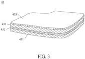
- FIG. 3 is a perspective diagram of a fireproof buffering structure 43 according to a third embodiment of the present application.
- the fireproof buffering structure 43 is a quadruple-layered structure and includes two buffering plates 431, a fireproof plate 432, and a first auxiliary fireproof plate 433.
- a surface of the fireproof plate 432 is attached to one of the two buffering plates 431, and a surface of the other buffering plate 431 is attached to another surface of the fireproof plate 432.
- the first auxiliary fireproof plate 433 is attached to a surface of the other buffering plate 431. Therefore, the first auxiliary fireproof plate 433 is attached to another surface of the other buffering plate 431 away from the fireproof plate 432.
- FIG. 4 is a perspective diagram of a fireproof buffering structure 44 according to a fourth embodiment of the present application.
- the fireproof buffering structure 44 is a quintuple-layered structure and includes two buffering plates 441, a fireproof plate 442, a first auxiliary fireproof plate 443, and a second auxiliary fireproof plate 444.
- Two surfaces of the two buffering plates 441 are respectively attached to a front surface of the fireproof plate 442 and a rear surface of the fireproof plate 442.
- the first auxiliary fireproof plate 443 and the second auxiliary fireproof plate 444 are respectively attached to two another surfaces of the two buffering plates 441. Therefore, the first auxiliary fireproof plate 443 and the second auxiliary fireproof plate 444 are respectively attached to the two another surfaces of the two buffering plates 441 away from the fireproof plate 442.
- FIG. 5 is a perspective diagram of a fireproof buffering structure 45 according to a fifth embodiment of the present application.
- the fireproof buffering structure 45 is a triple-layered structure and includes a buffering plate 451, a fireproof plate 452, and a first auxiliary fireproof plate 453.
- the fireproof plate 452 and the first auxiliary fireproof plate 453 are respectively attached to a front surface of the buffering plate 451 and a rear surface of the buffering plate 451.
- FIG. 6 is a perspective diagram of a fireproof buffering structure 46 according to a sixth embodiment of the present application. Based on the triple-layered structure of the fifth embodiment, other auxiliary layers are added to the triple-layered structure in the sixth embodiment.
- the fireproof buffering structure 46 includes three buffering plates 461, a fireproof plate 462, and a first auxiliary fireproof plate 463. A surface of the fireproof plate 462 and a surface of the first auxiliary fireproof plate 463 are respectively attached to a front surface and a rear surface of one of the three buffering plates 461, and the other two of the three buffering plates 461 are respectively attached to another surface of the fireproof plate 462 and another surface of the first auxiliary fireproof plate 463.
- FIG. 7 is a perspective diagram of a fireproof buffering structure 47 according to a seventh embodiment of the present application.
- the fireproof buffering structure 47 is a triple-layered structure and includes a buffering plate 471, a fireproof plate 472, and a first auxiliary fireproof plate 473. A surface of the fireproof plate 472 is attached to the buffering plate 471, and the first auxiliary fireproof plate 473 is attached to another surface of the fireproof plate 472.
- FIG. 8 is a perspective diagram of a fireproof buffering structure 48 according to an eighth embodiment of the present application.
- the fireproof buffering structure 48 includes two buffering plates 481, a fireproof plate 482, and a first auxiliary fireproof plate 483.
- a surface of the fireproof plate 482 is attached to one of the two buffering plates 481.
- a surface of the first auxiliary fireproof plate 483 is attached to another surface of the fireproof plate 482, and the other buffering plate 481 is attached to another surface of the first auxiliary fireproof plate 483.
- FIG. 9 is a perspective diagram of a fireproof buffering structure 49 according to a ninth embodiment of the present application.
- the fireproof buffering structure 49 includes two buffering plates 491, a fireproof plate 492, a first auxiliary fireproof plate 493, and a second auxiliary fireproof plate 494.
- the first auxiliary fireproof plate 493 and the fireproof plate 492 are attached between opposite surfaces of the two buffering plates 491 facing towards each other, and the second auxiliary fireproof plate 494 is attached to another surface of the two buffering plates 491 other than the opposite surfaces of the two buffering plates 491.
- FIG. 10 is a perspective diagram of a fireproof buffering structure 40 according to a tenth embodiment of the present application.
- the fireproof buffering structure 40 is a quintuple-layered structure and includes two buffering plates 401, a fireproof plate 402, a first auxiliary fireproof plate 403, and a second auxiliary fireproof plate 404.
- a surface of the fireproof plate 402 is attached to one of the two buffering plates 401
- a surface of the first auxiliary fireproof plate 403 is attached to another surface of the fireproof plate 402
- a surface of the second auxiliary fireproof plate 404 is attached to another surface of the first auxiliary fireproof plate 403, and the other buffering plate 401 is attached to another surface of the second auxiliary fireproof plate 404.
- the abovementioned buffering plates of the second embodiment to the tenth embodiment can be foam plates as the foam plate of the first embodiment.
- the fireproof plate, the first auxiliary fireproof plate, and the second auxiliary fireproof plate can be made of PE, PP, EPS, EPP, EPO, fireproof foam, EVA, or botanical cotton. Combustion rates of the first auxiliary fireproof plate and the second auxiliary fireproof plate are lower than the combustion rate of the buffering plates.
- two or all of the fireproof plate, the first auxiliary fireproof plate, and the second auxiliary fireproof plate can be made of the same material or different materials.
- the fireproof plate and the first auxiliary fireproof plate are made of different materials.
- the second auxiliary fireproof plate 494 of the ninth embodiment can be made of the same material as one of the fireproof plate 492 and the first auxiliary fireproof plate 493 or can be made of a material different from the fireproof plate 492 and the first auxiliary fireproof plate 493.
- the fireproof plate 402 and the second auxiliary fireproof plate 404 can be respectively made of a material different from the first auxiliary fireproof plate 403, while the fireproof plate 402 and the second auxiliary fireproof plate 404 can be made of the same material or different materials.
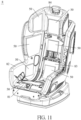
- FIG. 11 is a perspective diagram of a safety seat 8 with the fireproof buffering structure 50 of the present application.
- the present application further discloses the safety seat 8 with a fireproof buffering structure 50.
- the fireproof buffering structure 50 can be disposed on or directly attached on a main body of the safety seat 8.
- the buffering structure 50 can be attached to a position on at least one of a seat portion 81, a side portion 82, a backrest portion 83, and a headrest portion 84 of the main body.
- a shape of the buffering structure 50 can be strip-shaped, rectangular, or circular, but not limited thereto.
- the buffering structure 50 can be, but is not limited to, one of the buffering structures according to the first embodiment to the tenth embodiment. Besides, if an outmost layer of the fireproof buffering structure 50 is a fireproof plate, the fireproof plate is closer to a seating space of the safety seat 8 than the neighboring buffering plates or the buffering plate that the fireproof plate is attached to. That is, the buffering plates are positioned between the fireproof plate and an inner side of the safety seat 8 so that the fireproof plate is in contact with a child in the safety seat 8.
- FIG. 12 is a top view of the fireproof buffering structure 41 disposed to the headrest portion 84 according to the first embodiment of the present application.
- the fireproof buffering structures 41 are disposed on inner sides of two flanking sides of the headrest portion 84.
- the fireproof plates 412 are closer to an inner space surrounded by the headrest portion 84 than the buffering plates 411.
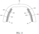
- FIG. 13 is a top view of the fireproof buffering structure 43 disposed to the headrest portion 84 according to the third embodiment of the present application.
- FIG. 13 is a top view of the fireproof buffering structure 43 disposed to the headrest portion 84 according to the third embodiment of the present application.
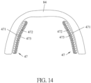
- FIG. 14 is a top view of the fireproof buffering structure disposed 47 to the headrest portion 84 according to the seventh embodiment of the present application.
- FIG. 15 is a top view of the fireproof buffering structure 49 disposed to the headrest portion 84 according to the ninth embodiment of the present application. As shown in FIG. 13 to FIG.
- the first auxiliary fireproof plates 433, 473 of the fireproof buffering structures 43, 47 respectively and the second auxiliary fireproof plates 494 of the fireproof buffering structures 49 are closer to an inner space surrounded by the headrest portion 84, while the buffering plates 431 of the fireproof buffering structures 43 are between the first auxiliary fireproof plates 433 and the inner sides of the headrest portion 84, and the buffering plates 471 of the fireproof buffering structures 47 are between the first auxiliary fireproof plates 473 and the inner sides of the headrest portion 84, and the buffering plates 491 of the fireproof buffering structures 49 are between the second auxiliary fireproof plate 494 and the inner sides of the headrest portion 84.
- FIG. 16 is a perspective diagram of the safety seat 3 with a supporting cushion apparatus 1 according to an embodiment of the present application.
- a safety seat 3 includes a main body 31 and the supporting cushion apparatus 1 disposed on the main body 31.
- the supporting cushion apparatus 1 can be a headrest for supporting the infant's head in the safety seat 3.
- the supporting cushion apparatus 1 includes the fireproof buffering structure disclosed by the present application so as to provide protection for the infant's head.
- FIG. 17 is a perspective diagram of the supporting cushion apparatus 1 according to the embodiment of the present application.
- FIG. 18 is a diagram of the fireproof buffering structure 45 partially accommodated in a covering pocket 113 according to an embodiment of the present application.
- the supporting apparatus 1 includes a covering member 11 and the fireproof buffering structure 45 accommodated inside the covering member 11.
- the fireproof buffering structure 45 can be a structure of the abovementioned fifth embodiment, which includes the buffering plate 451, and the fireproof plate 452 and the first auxiliary fireproof plate 453 respectively attached to a front surface of the buffering plate 451 and a rear surface of the buffering plate 451.
- the covering member 11 includes a head supporting portion 111 and two flanking portions 112 connected with two sides of the head supporting portion 111.
- a child in a car ride can rest his or her head on the head supporting portion 111.
- the fireproof buffering structure 45 can be accommodated in each of the two flanking portions 112 which are located on two sides of the child's head for providing protection.
- the covering pocket 113 with an opening can be disposed on at least one of the two flanking portions 112 and the head supporting portion 111, and the fireproof buffering structure 45 can be put into the covering pocket 113 through the opening.
- a shape of the fireproof buffering structure 45 can correspond to shapes of the flanking portion 112 and the covering pocket 113, and a size of the fireproof buffering structure 45 can be only slightly smaller than the covering pocket 113 so that the fireproof buffering structure 45 can be properly restrained in the flanking portion 112 after being enclosed into the covering pocket 113.
- the fireproof buffering structure 45 can also be accommodated in the head supporting portion 111.
- the fireproof buffering structures 45 are accommodated in the head supporting portion 111 and the flanking portions 112 of the covering member 11.
- the fireproof buffering structure 45 is accommodated only in the head supporting portion 111 but not in the flanking portions 112, and the description of the exemplary embodiments are intended to be illustrative and not to limit the scope of the invention.
- the fireproof plate 452 made of PE is harder than the buffering plate 451 and is disposed on a surface of the fireproof buffering structure 45 closer to an inner space surrounded by the covering member 11, the infant with his or her head rested in the inner space and on the fireproof plate 452 might feel uncomfortable. Therefore, a soft filler can be disposed on the fireproof plate 452 accommodated in the flanking portion 112.
- a side compartment can be disposed outside the covering pocket 113 accommodated in the flanking portion 112 or in the head supporting portion 111, and the soft filler can fill the side compartment.
- the soft filler can directly fill the covering pocket 113 for covering the fireproof plate 452 or can be disposed on the fireproof plate 452 accommodated in the covering pocket 113 or the head supporting portion 111, and the description of the exemplary embodiments are not intended to limit the scope of the invention but to be illustrative about that the soft filler is required to be positioned on an outer surface of the fireproof plate 452.
- the soft filler can be foam made of materials, such as PU, EPP, EPS, or EPE, or can be made of a material that improves comfortableness, such as cotton. It is noticed that the fireproof buffering structure accommodated in the supporting cushion apparatus 1 can be formed in other configurations else the fireproof buffering structures of the first embodiment to the tenth embodiment besides the abovementioned fireproof buffering structure 45.
- the fireproof buffering structure of the present application includes the buffering plate and the fireproof plate combined with each other.
- the buffering plate has good impact absorbing capacity for providing a soft and comfortable seating environment and buffering and protection effects during a crash accident.
- the attached fireproof plate can reduce the combustion rate of the integral structure when catching fire. Therefore, the fireproof buffering structure, which can be disposed in the safety seats 3, 8, achieves the inventive purposes of safety and comfort.
Landscapes
- Engineering & Computer Science (AREA)
- Aviation & Aerospace Engineering (AREA)
- Transportation (AREA)
- Mechanical Engineering (AREA)
- Health & Medical Sciences (AREA)
- Child & Adolescent Psychology (AREA)
- General Health & Medical Sciences (AREA)
- Chemical & Material Sciences (AREA)
- Materials Engineering (AREA)
- Organic Chemistry (AREA)
- Ceramic Engineering (AREA)
- Manufacturing & Machinery (AREA)
- Mattresses And Other Support Structures For Chairs And Beds (AREA)
- Seats For Vehicles (AREA)
- Vibration Dampers (AREA)
- Professional, Industrial, Or Sporting Protective Garments (AREA)
Abstract
Description
- The present invention relates to a fireproof buffering structure, a supporting cushion apparatus and a safety seat therewith according to the pre-characterizing clauses of
claims 1, 19, 24 and 28. - A child car safety seat provides a seating space with a suitable size for a child in a car ride, and buffering structures are disposed on surrounding walls of the child car safety seat which are in contact with the child to serve as a buffer during a crash so that possibility of injury to the child might be reduced. The buffering structure can be fixed to a main body of the safety seat and covered under a seat cloth, or the buffering structure can be disposed on the seat cloth. For example, a supporting cushion or a headrest is often mounted to the upper backrest portion of an infant basket safety seat for supporting and protecting an infant's head, and the buffering structure can be disposed inside the supporting cushion for improving safety.
- Conventional buffering structures are foams made of expanded polypropylene (EPP), expanded polystyrene (EPS) or expandable polyethylene (EPE) and in a shape of a plate or a block. The foams have good impact absorbing capacity for effective buffering. However, the foams are also flammable and have a higher combustion rate upon ignition, which is unsafe for application. Alternatively, the foams in the safety seat can be replaced by a flame-retardant material, but the hardness of the flame-retardant material reduces the impact absorbing capacity and comfort of the safety seat.
- Therefore, it is necessary to develop a buffering structure that combines buffering capacity and flame-retardant effect so as to improve safety and comfort of the safety seat.
- This in mind, the present invention aims at providing a buffering structure which combines buffering capacity and flame-retardant effect, a supporting cushion apparatus having the buffering structure, and a safety seat having the buffering structure or the supporting cushion apparatus.
- This is achieved by a fireproof buffering structure, a supporting cushion apparatus and a safety seat therewith according to
claims 1, 19, 24 and 28. The dependent claims pertain to corresponding further developments and improvements. - As will be seen more clearly from the detailed description following below, the claimed buffering structure includes a buffering plate and a fireproof plate attached to the buffering plate. A combustion rate of the fireproof plate is lower than a combustion rate of the buffering plate.
- Preferably, the buffering plate is a foam plate.
- Specifically, a density of the foam plate is substantially between 75 kg/m3 and 98 kg/m3.
- Preferably, the fireproof plate is made of at least one of polyethylene (PE), polypropylene (PP), expanded polystyrene (EPS), expanded polypropylene (EPP), expanded polystyrene (EPO), fireproof foam, ethylene-vinylacetate copolymer (EVA), and botanical cotton.
- Specifically, the botanical cotton is corn cotton.
- Preferably, a thickness of the fireproof buffering structure is substantially smaller than 13mm.
- Specifically, the thickness of the fireproof buffering structure is substantially equal to 12mm.
- Preferably, the fireproof buffering structure comprises a plurality of fireproof plates. At least part of the plurality of fireproof plates are made of different materials.
- Preferably, a shape of the fireproof plate corresponds to a shape of the buffering plate, and the fireproof plate is attached to a front surface of the buffering plate.
- Specifically, the fireproof buffering structure comprises two buffering plates respectively attached to a front surface of the fireproof plate and a rear surface of the fireproof plate.
- Specifically, the fireproof buffering structure further comprises a first auxiliary fireproof plate attached to a surface of the two buffering plates away from the fireproof plate.
- Specifically, the fireproof buffering structure further comprises a second auxiliary fireproof plate. The first auxiliary fireproof plate and the second auxiliary fireproof plate are respectively attached to two surfaces of the two buffering plates away from the fireproof plate.
- Specifically, the fireproof buffering structure further comprises a first auxiliary fireproof plate. The fireproof plate and the first auxiliary fireproof plate are respectively attached to a front surface of the buffering plate and a rear surface of the buffering plate.
- Specifically, the fireproof buffering structure comprises three buffering plates. A surface of the fireproof plate and a surface of the first auxiliary fireproof plate are respectively attached to a front surface and a rear surface of one of the three buffering plates, and the other two of the three buffering plates are respectively attached to an another surface of the fireproof plate and an another surface of the first auxiliary fireproof plate.
- Specifically, the fireproof buffering structure further comprises a first auxiliary fireproof plate. A surface of the fireproof plate is attached to the buffering plate, and the first auxiliary fireproof plate is attached to an another surface of the fireproof plate.
- Specifically, the fireproof buffering structure comprises two buffering plates. the fireproof plate is attached to one of the two buffering plates. A surface of the first auxiliary fireproof plate being attached to the fireproof plate, and the other one of the two buffering plates is attached to an another surface of the first auxiliary fireproof plate.
- Specifically, the fireproof buffering structure further comprises a second auxiliary fireproof plate. The first auxiliary fireproof plate and the fireproof plate are attached between opposite surfaces of the two buffering plates facing towards each other, and the second auxiliary fireproof plate is attached to an another surface of the two buffering plates other than the opposite surfaces of the two buffering plates.
- Specifically, the fireproof buffering structure comprises two buffering plates and further comprises a first auxiliary fireproof plate and a second auxiliary fireproof plate. A surface of the fireproof plate is attached to one of the two buffering plates. A surface of the first auxiliary fireproof plate is attached to an another surface of the fireproof plate. A surface of the second auxiliary fireproof plate being attached to an another surface of the first auxiliary fireproof plate, and the other one of the two buffering plates is attached to an another surface of the second auxiliary fireproof plate.
- Specifically, a combustion rate of the first auxiliary fireproof plate is lower than the combustion rate of the buffering plates.
- Specifically, combustion rates of the first auxiliary fireproof plate and the second auxiliary fireproof plate are lower than the combustion rate of the buffering plates.
- As will be seen more clearly from the detailed description following below, the claimed supporting cushion apparatus includes a covering member and the abovementioned fireproof buffering structure accommodated inside the covering member.
- Preferably, the covering member comprises a head supporting portion and two flanking portions connected with two sides of the head supporting portion, and the fireproof buffering structure is accommodated in at least one of the head supporting portion and the two flanking portions.
- Specifically, a covering pocket is disposed on at least one of the head supporting portion and the two flanking portions, and the fireproof buffering structure is accommodated in the covering pocket.
- Specifically, a soft filler is disposed on a surface of the fireproof buffering structure accommodated in at least one of the covering pocket and the head supporting portion and the two flanking portions.
- Specifically, a side compartment is disposed outside the covering pocket in at least one of the head supporting portion and the two flanking portions, and the soft filler fills the side compartment.
- As will be seen more clearly from the detailed description following below, the claimed safety seat includes a main body and the abovementioned fireproof buffering structure disposed on the main body.
- Preferably, the fireproof buffering structure is attached on the main body.
- Specifically, the fireproof buffering structure is attached on at least one of a seat portion and a side portion and a backrest portion of the main body.
- Specifically, the fireproof plate of the fireproof buffering structure is closer to a seating space of the safety seat than the buffering plate, and the buffering plate is positioned between the fireproof plate and an inner side of the safety seat.
- As will be seen more clearly from the detailed description following below, another claimed safety seat includes a main body and the abovementioned supporting cushion apparatus disposed on the main body.
- In contrast to conventional buffering structures, the fireproof buffering structure of the present application includes the buffering plate and the fireproof plate combined with each other. The buffering plate has good impact absorbing capacity for providing a soft and comfortable seating environment and buffering and protection effects during a crash accident. Besides, the attached fireproof plate can reduce the combustion rate of the integral structure when catching fire. Therefore, the fireproof buffering structure, which can be disposed in the
safety seats 3, 8, achieves the inventive purposes of safety and comfort. - These and other objectives of the present invention will no doubt become obvious to those of ordinary skill in the art after reading the following detailed description of the preferred embodiment that is illustrated in the various figures and drawings.
- In the following, the invention is further illustrated by way of example, taking reference to the accompanying drawings. Thereof
-
FIG. 1 is a perspective diagram of a fireproof buffering structure according to a first embodiment of the present application, -
FIG. 2 is a perspective diagram of a fireproof buffering structure according to a second embodiment of the present application, -
FIG. 3 is a perspective diagram of a fireproof buffering structure according to a third embodiment of the present application, -
FIG. 4 is a perspective diagram of a fireproof buffering structure according to a fourth embodiment of the present application, -
FIG. 5 is a perspective diagram of a fireproof buffering structure according to a fifth embodiment of the present application, -
FIG. 6 is a perspective diagram of a fireproof buffering structure according to a sixth embodiment of the present application, -
FIG. 7 is a perspective diagram of a fireproof buffering structure according to a seventh embodiment of the present application, -
FIG. 8 is a perspective diagram of a fireproof buffering structure according to an eighth embodiment of the present application, -
FIG. 9 is a perspective diagram of a fireproof buffering structure according to a ninth embodiment of the present application, -
FIG. 10 is a perspective diagram of a fireproof buffering structure according to a tenth embodiment of the present application, -
FIG. 11 is a perspective diagram of a safety seat with the fireproof buffering structure of the present application, -
FIG. 12 is a top view of the fireproof buffering structure disposed to a headrest portion according to the first embodiment of the present application, -
FIG. 13 is a top view of the fireproof buffering structure disposed to the headrest portion according to the third embodiment of the present application, -
FIG. 14 is a top view of the fireproof buffering structure disposed to the headrest portion according to the seventh embodiment of the present application, -
FIG. 15 is a top view of the fireproof buffering structure disposed to the headrest portion according to the ninth embodiment of the present application, -
FIG. 16 is a perspective diagram of the safety seat with a supporting cushion apparatus according to an embodiment of the present application, -
FIG. 17 is a perspective diagram of the supporting cushion apparatus according to the embodiment of the present application, and -
FIG. 18 is a diagram of the fireproof buffering structure partially accommodated in a covering pocket according to an embodiment of the present application. - Please refer to
FIG. 1. FIG. 1 is a perspective diagram of afireproof buffering structure 41 according to a first embodiment of the present application. Thefireproof structure 41 provided by the present application is mainly used in a child safety seat. Thefireproof buffering structure 41 includes abuffering plate 411 and afireproof plate 412 attached to thebuffering plate 411. Thebuffering plate 411 is made of soft material and thereby has good buffering and impact absorbing capacity for protecting an infant's head from fierce impact during an accident. A combustion rate (and a flammability) of thefireproof plate 412 is lower than a combustion rate of thebuffering plate 411, so a cross-sectional combustion rate of the integratedbuffering plate 411 andfireproof plate 412 is lower than a cross-sectional combustion rate of thebuffering plate 411 alone. Thebuffering plate 411 can be a foam plate made of material such as polyurethane (PU), expanded polypropylene (EPP), expanded polystyrene (EPS) or Expandable Polyethylene (EPE). Thebuffering plate 411 of the present application can be a foam plate with a density substantially between 75 kg/m3 and 98 kg/m3. Specifically, the foam plate can be made of inert foam, and the density can be substantially 98 kg/m3. Specifically, thefireproof plate 412 can be made of polyethylene (PE), polypropylene (PP), EPS, EPP, expanded polystyrene (EPO), fireproof foam, ethylene-vinylacetate copolymer (EVA), or botanical cotton, and the botanical cotton can be corn cotton. A thickness of thefireproof buffering structure 41 can be substantially smaller than 13mm, preferably 12mm. Thebuffering plate 411 and thefireproof plate 412 are attached to each other via, but not limited to, glue or twin adhesive, and a shape of thefireproof plate 412 can correspond to a shape of thebuffering plate 411. - Besides a double-layered structure of the fireproof buffering structure mentioned above, the fireproof buffering structure of the present application can also be, but is not limited to, a triple-layered structure, a quadruple-layered structure, or a quintuple-layered structure, which is described as follows.
- Please refer to
FIG. 2. FIG. 2 is a perspective diagram of afireproof buffering structure 42 according to a second embodiment of the present application. Thefireproof buffering structure 42 is a triple-layered structure and includes afireproof plate 422 and twobuffering plates 421. The twobuffering plates 421 are respectively attached to a front surface of thefireproof plate 422 and a rear surface of thefireproof plate 422. - Based on the triple-layered structure of the second embodiment, other auxiliary layers are added to the triple-layered structure, which is described in a third and a fourth embodiments as follows.
- Please refer to
FIG. 3. FIG. 3 is a perspective diagram of afireproof buffering structure 43 according to a third embodiment of the present application. Thefireproof buffering structure 43 is a quadruple-layered structure and includes two bufferingplates 431, afireproof plate 432, and a first auxiliaryfireproof plate 433. A surface of thefireproof plate 432 is attached to one of the twobuffering plates 431, and a surface of theother buffering plate 431 is attached to another surface of thefireproof plate 432. The first auxiliaryfireproof plate 433 is attached to a surface of theother buffering plate 431. Therefore, the first auxiliaryfireproof plate 433 is attached to another surface of theother buffering plate 431 away from thefireproof plate 432. - Please refer to
FIG. 4. FIG. 4 is a perspective diagram of afireproof buffering structure 44 according to a fourth embodiment of the present application. Thefireproof buffering structure 44 is a quintuple-layered structure and includes two bufferingplates 441, a fireproof plate 442, a first auxiliaryfireproof plate 443, and a second auxiliaryfireproof plate 444. Two surfaces of the twobuffering plates 441 are respectively attached to a front surface of the fireproof plate 442 and a rear surface of the fireproof plate 442. The first auxiliaryfireproof plate 443 and the second auxiliaryfireproof plate 444 are respectively attached to two another surfaces of the twobuffering plates 441. Therefore, the first auxiliaryfireproof plate 443 and the second auxiliaryfireproof plate 444 are respectively attached to the two another surfaces of the twobuffering plates 441 away from the fireproof plate 442. - Please refer to
FIG.5. FIG. 5 is a perspective diagram of afireproof buffering structure 45 according to a fifth embodiment of the present application. Thefireproof buffering structure 45 is a triple-layered structure and includes abuffering plate 451, afireproof plate 452, and a first auxiliaryfireproof plate 453. Thefireproof plate 452 and the first auxiliaryfireproof plate 453 are respectively attached to a front surface of thebuffering plate 451 and a rear surface of thebuffering plate 451. - Please refer to
Fig. 6. FIG. 6 is a perspective diagram of afireproof buffering structure 46 according to a sixth embodiment of the present application. Based on the triple-layered structure of the fifth embodiment, other auxiliary layers are added to the triple-layered structure in the sixth embodiment. Thefireproof buffering structure 46 includes threebuffering plates 461, afireproof plate 462, and a first auxiliaryfireproof plate 463. A surface of thefireproof plate 462 and a surface of the first auxiliaryfireproof plate 463 are respectively attached to a front surface and a rear surface of one of the threebuffering plates 461, and the other two of the threebuffering plates 461 are respectively attached to another surface of thefireproof plate 462 and another surface of the first auxiliaryfireproof plate 463. - Please refer to
FIG. 7. FIG. 7 is a perspective diagram of afireproof buffering structure 47 according to a seventh embodiment of the present application. Thefireproof buffering structure 47 is a triple-layered structure and includes abuffering plate 471, afireproof plate 472, and a first auxiliaryfireproof plate 473. A surface of thefireproof plate 472 is attached to thebuffering plate 471, and the first auxiliaryfireproof plate 473 is attached to another surface of thefireproof plate 472. - Based on the triple-layered structure of the seventh embodiment, other auxiliary layers are added to the triple-layered structure, which is described in an eighth embodiment and a ninth embodiment as follows.
- Please refer to
FIG. 8. FIG. 8 is a perspective diagram of afireproof buffering structure 48 according to an eighth embodiment of the present application. Thefireproof buffering structure 48 includes two bufferingplates 481, afireproof plate 482, and a first auxiliaryfireproof plate 483. A surface of thefireproof plate 482 is attached to one of the twobuffering plates 481. A surface of the first auxiliaryfireproof plate 483 is attached to another surface of thefireproof plate 482, and theother buffering plate 481 is attached to another surface of the first auxiliaryfireproof plate 483. - Please refer to
FIG. 9. FIG. 9 is a perspective diagram of afireproof buffering structure 49 according to a ninth embodiment of the present application. Thefireproof buffering structure 49 includes two bufferingplates 491, afireproof plate 492, a first auxiliaryfireproof plate 493, and a second auxiliaryfireproof plate 494. The first auxiliaryfireproof plate 493 and thefireproof plate 492 are attached between opposite surfaces of the twobuffering plates 491 facing towards each other, and the second auxiliaryfireproof plate 494 is attached to another surface of the twobuffering plates 491 other than the opposite surfaces of the twobuffering plates 491. - Please refer to
FIG. 10. FIG. 10 is a perspective diagram of afireproof buffering structure 40 according to a tenth embodiment of the present application. Thefireproof buffering structure 40 is a quintuple-layered structure and includes two bufferingplates 401, a fireproof plate 402, a first auxiliaryfireproof plate 403, and a second auxiliaryfireproof plate 404. A surface of the fireproof plate 402 is attached to one of the twobuffering plates 401, a surface of the first auxiliaryfireproof plate 403 is attached to another surface of the fireproof plate 402, a surface of the second auxiliaryfireproof plate 404 is attached to another surface of the first auxiliaryfireproof plate 403, and theother buffering plate 401 is attached to another surface of the second auxiliaryfireproof plate 404. - The abovementioned buffering plates of the second embodiment to the tenth embodiment can be foam plates as the foam plate of the first embodiment. The fireproof plate, the first auxiliary fireproof plate, and the second auxiliary fireproof plate can be made of PE, PP, EPS, EPP, EPO, fireproof foam, EVA, or botanical cotton. Combustion rates of the first auxiliary fireproof plate and the second auxiliary fireproof plate are lower than the combustion rate of the buffering plates. For the third embodiment to the sixth embodiment, two or all of the fireproof plate, the first auxiliary fireproof plate, and the second auxiliary fireproof plate can be made of the same material or different materials. For the seventh embodiment to the ninth embodiment, the fireproof plate and the first auxiliary fireproof plate are made of different materials. The second auxiliary
fireproof plate 494 of the ninth embodiment can be made of the same material as one of thefireproof plate 492 and the first auxiliaryfireproof plate 493 or can be made of a material different from thefireproof plate 492 and the first auxiliaryfireproof plate 493. For the tenth embodiment, the fireproof plate 402 and the second auxiliaryfireproof plate 404 can be respectively made of a material different from the first auxiliaryfireproof plate 403, while the fireproof plate 402 and the second auxiliaryfireproof plate 404 can be made of the same material or different materials. By adjusting the materials of the multiple fireproof plates, an integral combustion rate of the fireproof buffering structure can be adjusted. Besides, the fireproof plates are usually harder than the buffering plates, which can transfer an impact onto the entire buffering plates during a crash accident so that the buffering plates are deformed uniformly to achieve better buffering effect. - Please refer to
FIG. 11. FIG. 11 is a perspective diagram of asafety seat 8 with thefireproof buffering structure 50 of the present application. The present application further discloses thesafety seat 8 with afireproof buffering structure 50. Thefireproof buffering structure 50 can be disposed on or directly attached on a main body of thesafety seat 8. For example, thebuffering structure 50 can be attached to a position on at least one of aseat portion 81, aside portion 82, abackrest portion 83, and aheadrest portion 84 of the main body. According to the position where thebuffering structure 50 is attached, a shape of thebuffering structure 50 can be strip-shaped, rectangular, or circular, but not limited thereto. It is noticed that thebuffering structure 50 can be, but is not limited to, one of the buffering structures according to the first embodiment to the tenth embodiment. Besides, if an outmost layer of thefireproof buffering structure 50 is a fireproof plate, the fireproof plate is closer to a seating space of thesafety seat 8 than the neighboring buffering plates or the buffering plate that the fireproof plate is attached to. That is, the buffering plates are positioned between the fireproof plate and an inner side of thesafety seat 8 so that the fireproof plate is in contact with a child in thesafety seat 8. - Further detail of that the abovementioned fireproof buffering structures are configured for the first embodiment, the third embodiment, the seventh embodiment, and the ninth embodiment is described as follows. Please refer to
FIG. 12. FIG. 12 is a top view of thefireproof buffering structure 41 disposed to theheadrest portion 84 according to the first embodiment of the present application. As shown inFIG. 12 , thefireproof buffering structures 41 are disposed on inner sides of two flanking sides of theheadrest portion 84. Thefireproof plates 412 are closer to an inner space surrounded by theheadrest portion 84 than the bufferingplates 411. Please refer toFIG. 13 to FIG. 15 .FIG. 13 is a top view of thefireproof buffering structure 43 disposed to theheadrest portion 84 according to the third embodiment of the present application.FIG. 14 is a top view of the fireproof buffering structure disposed 47 to theheadrest portion 84 according to the seventh embodiment of the present application.FIG. 15 is a top view of thefireproof buffering structure 49 disposed to theheadrest portion 84 according to the ninth embodiment of the present application. As shown inFIG. 13 to FIG. 15 , the first auxiliaryfireproof plates fireproof buffering structures fireproof plates 494 of thefireproof buffering structures 49 are closer to an inner space surrounded by theheadrest portion 84, while thebuffering plates 431 of thefireproof buffering structures 43 are between the first auxiliaryfireproof plates 433 and the inner sides of theheadrest portion 84, and thebuffering plates 471 of thefireproof buffering structures 47 are between the first auxiliaryfireproof plates 473 and the inner sides of theheadrest portion 84, and thebuffering plates 491 of thefireproof buffering structures 49 are between the second auxiliaryfireproof plate 494 and the inner sides of theheadrest portion 84. - Please refer to
FIG. 16. FIG. 16 is a perspective diagram of the safety seat 3 with a supportingcushion apparatus 1 according to an embodiment of the present application. As shown inFIG. 16 , the present application further discloses that a safety seat 3 includes amain body 31 and the supportingcushion apparatus 1 disposed on themain body 31. The supportingcushion apparatus 1 can be a headrest for supporting the infant's head in the safety seat 3. The supportingcushion apparatus 1 includes the fireproof buffering structure disclosed by the present application so as to provide protection for the infant's head. - Please refer to
FIG. 17 andFIG. 18 .FIG. 17 is a perspective diagram of the supportingcushion apparatus 1 according to the embodiment of the present application.FIG. 18 is a diagram of thefireproof buffering structure 45 partially accommodated in acovering pocket 113 according to an embodiment of the present application. The supportingapparatus 1 includes a coveringmember 11 and thefireproof buffering structure 45 accommodated inside the coveringmember 11. Thefireproof buffering structure 45 can be a structure of the abovementioned fifth embodiment, which includes thebuffering plate 451, and thefireproof plate 452 and the first auxiliaryfireproof plate 453 respectively attached to a front surface of thebuffering plate 451 and a rear surface of thebuffering plate 451. The coveringmember 11 includes ahead supporting portion 111 and two flankingportions 112 connected with two sides of thehead supporting portion 111. A child in a car ride can rest his or her head on thehead supporting portion 111. Thefireproof buffering structure 45 can be accommodated in each of the two flankingportions 112 which are located on two sides of the child's head for providing protection. Specifically, the coveringpocket 113 with an opening can be disposed on at least one of the two flankingportions 112 and thehead supporting portion 111, and thefireproof buffering structure 45 can be put into thecovering pocket 113 through the opening. A shape of thefireproof buffering structure 45 can correspond to shapes of the flankingportion 112 and thecovering pocket 113, and a size of thefireproof buffering structure 45 can be only slightly smaller than the coveringpocket 113 so that thefireproof buffering structure 45 can be properly restrained in the flankingportion 112 after being enclosed into thecovering pocket 113. Thefireproof buffering structure 45 can also be accommodated in thehead supporting portion 111. For example, in another embodiment of the present application, thefireproof buffering structures 45 are accommodated in thehead supporting portion 111 and the flankingportions 112 of the coveringmember 11. In another embodiment of the present application, thefireproof buffering structure 45 is accommodated only in thehead supporting portion 111 but not in the flankingportions 112, and the description of the exemplary embodiments are intended to be illustrative and not to limit the scope of the invention. - Since the
fireproof plate 452 made of PE is harder than thebuffering plate 451 and is disposed on a surface of thefireproof buffering structure 45 closer to an inner space surrounded by the coveringmember 11, the infant with his or her head rested in the inner space and on thefireproof plate 452 might feel uncomfortable. Therefore, a soft filler can be disposed on thefireproof plate 452 accommodated in the flankingportion 112. A side compartment can be disposed outside the coveringpocket 113 accommodated in the flankingportion 112 or in thehead supporting portion 111, and the soft filler can fill the side compartment. In other embodiments, the soft filler can directly fill thecovering pocket 113 for covering thefireproof plate 452 or can be disposed on thefireproof plate 452 accommodated in thecovering pocket 113 or thehead supporting portion 111, and the description of the exemplary embodiments are not intended to limit the scope of the invention but to be illustrative about that the soft filler is required to be positioned on an outer surface of thefireproof plate 452. The soft filler can be foam made of materials, such as PU, EPP, EPS, or EPE, or can be made of a material that improves comfortableness, such as cotton. It is noticed that the fireproof buffering structure accommodated in the supportingcushion apparatus 1 can be formed in other configurations else the fireproof buffering structures of the first embodiment to the tenth embodiment besides the abovementionedfireproof buffering structure 45. - In contrast to conventional buffering structures, the fireproof buffering structure of the present application includes the buffering plate and the fireproof plate combined with each other. The buffering plate has good impact absorbing capacity for providing a soft and comfortable seating environment and buffering and protection effects during a crash accident. Besides, the attached fireproof plate can reduce the combustion rate of the integral structure when catching fire. Therefore, the fireproof buffering structure, which can be disposed in the
safety seats 3, 8, achieves the inventive purposes of safety and comfort. - Those skilled in the art will readily observe that numerous modifications and alterations of the device and method may be made while retaining the teachings of the invention.
Claims (15)
- A child safety car seat (8) comprising:a main body (31); anda fireproof buffering structure (41, 42, 43, 44, 45, 46, 47, 48, 49, 40, 50) disposed on the main body (31), the fireproof buffering structure (41, 42, 43, 44, 45, 46, 47, 48, 49, 40, 50) comprising:a buffering plate (411, 421, 431, 441, 451, 461, 471, 481, 491, 401); anda fireproof plate (412, 422, 432, 442, 452, 462, 472, 482, 492, 402) attached to or neighboring to the buffering plate (411, 421, 431, 441, 451, 461, 471, 481, 491, 401),the fireproof plate (412, 422, 432, 442, 452, 462, 472, 482, 492, 402) being closer to a seating space of the child safety car seat (8) than the buffering plate (411, 421, 431, 441, 451, 461, 471, 481, 491, 401),the buffering plate (411, 421, 431, 441, 451, 461, 471, 481, 491, 401) being positioned between the fireproof plate (412, 422, 432, 442, 452, 462, 472, 482, 492, 402) and an inner side of the child safety car seat (8); anda combustion rate of the fireproof plate (412, 422, 432, 442, 452, 462, 472, 482, 492, 402) being lower than a combustion rate of the buffering plate (411, 421, 431, 441, 451, 461, 471, 481, 491, 401).
- The child safety car seat (8) of claim 1, wherein the fireproof plate (412, 422, 432, 442, 452, 462, 472, 482, 492, 402) is harder than the buffering plate (411, 421, 431, 441, 451, 461, 471, 481, 491, 401); and/or
wherein a thickness of the fireproof plate (412, 422, 432, 442, 452, 462, 472, 482, 492, 402) is smaller than a thickness of the buffering plate (411, 421, 431, 441, 451, 461, 471, 481, 491, 401). - The child safety car seat (8) of claim 1 or 2, wherein the buffering plate (411, 421, 431, 441, 451, 461, 471, 481, 491, 401) is a foam plate and a density of the buffering plate (411, 421, 431, 441, 451, 461, 471, 481, 491, 401) is substantially between 75 kg/m3 and 98 kg/m3; and/or,
wherein the fireproof plate (412, 422, 432, 442, 452, 462, 472, 482, 492, 402) is made of at least one of polyethylene (PE), polypropylene (PP), expanded polystyrene (EPS), expanded polypropylene (EPP), expanded polystyrene (EPO), fireproof foam, ethylene-vinylacetate copolymer (EVA), and botanical cotton. - The child safety car seat (8) of any one of claims 1 to 3, wherein the fireproof buffering structure (41, 42, 43, 44, 45, 46, 47, 48, 49, 40, 50) comprises a plurality of fireproof plates, and at least part of the plurality of fireproof plates are made of different materials.
- The child safety car seat (8) of any one of claims 1 to 4, wherein a shape of the fireproof plate (412, 422, 432, 442, 452, 462, 472, 482, 492, 402) corresponds to a shape of the buffering plate (411, 421, 431, 441, 451, 461, 471, 481, 491, 401), and the fireproof plate (412, 422, 432, 442, 452, 462, 472, 482, 492, 402) is attached to a surface of the buffering plate (411, 421, 431, 441, 451, 461, 471, 481, 491, 401).
- The child safety car seat (8) of any one of claims 1 to 5, wherein the fireproof buffering structure (42, 43, 44, 46, 48, 49, 40) comprises two buffering plates (421, 431, 441, 461, 481, 491, 401) respectively attached to two opposite surfaces of the fireproof plate (422, 432, 442, 462, 482, 492, 402).
- The child safety car seat (8) of claim 6, wherein the fireproof buffering structure (43, 44, 46) further comprises a first auxiliary fireproof plate (433, 443, 463) attached to a surface of one of the two buffering plates (431, 441, 461) away from the fireproof plate (432, 442, 462) and adjacent to the seating space of the child safety car seat (8).
- The child safety car seat (8) of any one of claims 1 to 5, wherein the fireproof buffering structure (47, 48, 49, 40) further comprises a first auxiliary fireproof plate (473, 483, 493, 403), the fireproof plate (472, 482, 492, 402) is attached between the buffering plate (471, 481, 491, 401) and the first auxiliary fireproof plate (473, 483, 493, 403), and the buffering plate (471, 481, 491, 401) and the first auxiliary fireproof plate (473, 483, 493, 403) are attached to two opposite surfaces of the fireproof plate (472, 482, 492, 402).
- The child safety car seat (8) of any one of claims 1 to 5, wherein the fireproof buffering structure (48, 49) comprises two buffering plates (481, 491) and further comprises a first auxiliary fireproof plate (483, 493), a surface of the fireproof plate (482, 492) is attached to one of the two buffering plates (481, 491), a surface of the first auxiliary fireproof plate (483, 493) is attached to another surface of the fireproof plate (482, 492), and the other one of the two buffering plates (481, 491) is attached to an another surface of the first auxiliary fireproof plate (483, 493).
- The child safety car seat (8) of claim 9, wherein the fireproof buffering structure (49) further comprises a second auxiliary fireproof plate (494), the first auxiliary fireproof plate (493) and the fireproof plate (492) are attached between opposite surfaces of the two buffering plates (491) facing towards each other, and the second auxiliary fireproof plate (494) is attached to an another surface of the one of the two buffering plates (491) other than the opposite surfaces of the two buffering plates (491).
- The child safety car seat (8) of claim 10, wherein combustion rates of the first auxiliary fireproof plate (493) and the second auxiliary fireproof (494) are lower than the combustion rate of the buffering plates (491).
- The child safety car seat (8) of any one of claims 1 to 11, wherein the fireproof buffering structure (50) is attached on at least one of a seat portion (81), a side portion (82), a backrest portion (83) and a headrest portion (84) of the main body (31).
- The child safety car seat (8) of claim 12, the fireproof buffering structure (50) disposed at the headrest portion (84) has a different structure from the fireproof buffering structure (50) disposed at the side portion (82).
- The child safety car seat (8) of any one of claims 1 to 3, 5, 12 and 13, wherein the fireproof plate (412, 452) is positioned at an outmost layer of the fireproof buffering structure (41, 45, 50).
- The child safety car seat (8) of any one of claims 1 to 3, 5, 12 and 13, wherein the fireproof buffering structure (45, 50) is a triple-layered structure and further comprises a first auxiliary fireproof plate (453), and the fireproof plate (452) and the first auxiliary fireproof plate (453) are respectively attached to a front surface of the buffering plate (451) and a rear surface of the buffering plate (451).
Applications Claiming Priority (5)
| Application Number | Priority Date | Filing Date | Title |
|---|---|---|---|
| CN201720939006 | 2017-07-28 | ||
| CN201810551224.XA CN109263196A (en) | 2017-07-28 | 2018-05-31 | Fireproof cushioning structure, support cushion device and safety seat |
| EP22188718.5A EP4105073B1 (en) | 2017-07-28 | 2018-07-26 | Fireproof buffering structure, supporting cushion apparatus and safety seat therewith |
| EP20154141.4A EP3663127B1 (en) | 2017-07-28 | 2018-07-26 | Fireproof buffering structure, supporting cushion apparatus and safety seat therewith |
| EP18185705.3A EP3437924B1 (en) | 2017-07-28 | 2018-07-26 | Fireproof buffering structure, supporting cushion apparatus and safety seat therewith |
Related Parent Applications (3)
| Application Number | Title | Priority Date | Filing Date |
|---|---|---|---|
| EP22188718.5A Division EP4105073B1 (en) | 2017-07-28 | 2018-07-26 | Fireproof buffering structure, supporting cushion apparatus and safety seat therewith |
| EP20154141.4A Division EP3663127B1 (en) | 2017-07-28 | 2018-07-26 | Fireproof buffering structure, supporting cushion apparatus and safety seat therewith |
| EP18185705.3A Division EP3437924B1 (en) | 2017-07-28 | 2018-07-26 | Fireproof buffering structure, supporting cushion apparatus and safety seat therewith |
Publications (2)
| Publication Number | Publication Date |
|---|---|
| EP4501640A2 true EP4501640A2 (en) | 2025-02-05 |
| EP4501640A3 EP4501640A3 (en) | 2025-03-19 |
Family
ID=63077733
Family Applications (4)
| Application Number | Title | Priority Date | Filing Date |
|---|---|---|---|
| EP18185705.3A Active EP3437924B1 (en) | 2017-07-28 | 2018-07-26 | Fireproof buffering structure, supporting cushion apparatus and safety seat therewith |
| EP22188718.5A Active EP4105073B1 (en) | 2017-07-28 | 2018-07-26 | Fireproof buffering structure, supporting cushion apparatus and safety seat therewith |
| EP20154141.4A Active EP3663127B1 (en) | 2017-07-28 | 2018-07-26 | Fireproof buffering structure, supporting cushion apparatus and safety seat therewith |
| EP24219954.5A Pending EP4501640A3 (en) | 2017-07-28 | 2018-07-26 | Fireproof buffering structure, supporting cushion apparatus and safety seat therewith |
Family Applications Before (3)
| Application Number | Title | Priority Date | Filing Date |
|---|---|---|---|
| EP18185705.3A Active EP3437924B1 (en) | 2017-07-28 | 2018-07-26 | Fireproof buffering structure, supporting cushion apparatus and safety seat therewith |
| EP22188718.5A Active EP4105073B1 (en) | 2017-07-28 | 2018-07-26 | Fireproof buffering structure, supporting cushion apparatus and safety seat therewith |
| EP20154141.4A Active EP3663127B1 (en) | 2017-07-28 | 2018-07-26 | Fireproof buffering structure, supporting cushion apparatus and safety seat therewith |
Country Status (6)
| Country | Link |
|---|---|
| US (5) | US10851304B2 (en) |
| EP (4) | EP3437924B1 (en) |
| CN (2) | CN109263196A (en) |
| CA (1) | CA3012520C (en) |
| DE (1) | DE202018006150U1 (en) |
| ES (1) | ES3014909T3 (en) |
Families Citing this family (7)
| Publication number | Priority date | Publication date | Assignee | Title |
|---|---|---|---|---|
| CN109263196A (en) * | 2017-07-28 | 2019-01-25 | 明门(中国)幼童用品有限公司 | Fireproof cushioning structure, support cushion device and safety seat |
| CN113386639A (en) | 2020-03-13 | 2021-09-14 | 宝钜瑞士股份有限公司 | Child safety seat |
| CN113815502B (en) | 2020-06-19 | 2024-07-26 | 宝钜瑞士股份有限公司 | Child safety seat and side-impact protection mechanism thereof |
| CN118544909A (en) | 2020-06-30 | 2024-08-27 | 宝钜瑞士股份有限公司 | Child safety seat and side-impact protection mechanism thereof |
| CN115675207A (en) * | 2021-07-30 | 2023-02-03 | 明门(中国)幼童用品有限公司 | child safety seat |
| TW202517478A (en) * | 2023-07-14 | 2025-05-01 | 瑞士商明門瑞士股份有限公司 | Side impact protection on car seat |
| US20250042313A1 (en) * | 2023-08-01 | 2025-02-06 | Graco Children's Products Inc. | Child restraint system including internal side impact surfaces |
Family Cites Families (27)
| Publication number | Priority date | Publication date | Assignee | Title |
|---|---|---|---|---|
| NL8600242A (en) * | 1986-01-31 | 1987-08-17 | Gechem Nv | FIRE-RESISTANT INTERMEDIATE COVER FOR SEATING AND SEATING FURNITURE INCLUDING SUCH INTERIOR COATINGS. |
| DE3853082D1 (en) * | 1987-06-02 | 1995-03-23 | Greiner & Soehne C A | Seat with a foam plastic pad. |
| US4779930A (en) * | 1987-09-17 | 1988-10-25 | Rosen Steven B | Infant head support for use with infant retaining devices |
| US4892769A (en) * | 1988-04-29 | 1990-01-09 | Weyerhaeuser Company | Fire resistant thermoplastic material containing absorbent article |
| US4948648A (en) * | 1989-12-11 | 1990-08-14 | Ethyl Corporation | Fire resistant laminar cushioning material |
| US5137777A (en) * | 1990-12-11 | 1992-08-11 | Ametek | Fire-retardant polymer foam composites |
| DE19736976A1 (en) * | 1997-08-25 | 1999-03-04 | Basf Ag | Production of flexible polyurethane foams with increased compression hardness |
| FR2836470B1 (en) * | 2002-02-25 | 2004-07-09 | J S O | MELANIN FOAM MATTRESS AND APPLICATIONS THEREOF |
| US20050026528A1 (en) * | 2003-07-29 | 2005-02-03 | Forsten Herman Hans | Fire resistant fabric composite, process for fire-blocking a mattress and mattress set, and a mattress and mattress set fire-blocked thereby |
| US7234771B2 (en) * | 2003-10-23 | 2007-06-26 | Britax Child Safety, Inc. | Child safety seat with adjustable head restraint |
| US7421750B2 (en) * | 2005-11-03 | 2008-09-09 | E.I. Du Pont De Nemours And Company | Pillow-top mattress comprising a fire blocked gusset |
| US20080136231A1 (en) * | 2006-09-01 | 2008-06-12 | Brian Doherty | Infant and child car seat for thermally conditioning a body |
| WO2009079253A2 (en) * | 2007-12-11 | 2009-06-25 | Be Aerospace, Inc. | Insulating cover for flammable cushioning materials |
| DE102010035845B4 (en) | 2010-08-30 | 2016-05-12 | Johnson Controls Gmbh | Car seat cover |
| US20130174344A1 (en) | 2012-01-09 | 2013-07-11 | Steve Klancnik | Component with multiple layers |
| US8745795B2 (en) * | 2012-01-09 | 2014-06-10 | Serta, Inc. | Bedding component with fire-resistant laminate |
| CN202553107U (en) * | 2012-05-07 | 2012-11-28 | 侯光雄 | Pad structure |
| AU2013267054B2 (en) * | 2013-12-05 | 2017-07-13 | Dorel Australia Pty Ltd | Energy-dissipation system |
| US8690237B2 (en) * | 2012-06-07 | 2014-04-08 | Graco Children's Products Inc. | Child car seat and headrest with side impact energy absorption |
| US9113720B2 (en) * | 2013-02-25 | 2015-08-25 | Nathalie Bourgoin | Infant seat cover |
| CN104553901A (en) * | 2013-10-14 | 2015-04-29 | 明门香港股份有限公司 | Child safety seat |
| US20150175036A1 (en) * | 2013-12-23 | 2015-06-25 | Paul Gaudreau, JR. | Child car seats and related methods |
| US9365136B2 (en) * | 2014-03-26 | 2016-06-14 | The Bird And Bear Group Llc | Insert for a child's seat |
| US10144319B2 (en) * | 2014-09-04 | 2018-12-04 | Dianne Tomita Stevens-Poire′ | Carrier with shock absorbing material |
| DK3066963T3 (en) * | 2015-03-11 | 2020-11-23 | Tempur World Llc | SUPPORT CUSHIONS INCLUDING A MIXED FILLING |
| CN206297439U (en) * | 2016-08-26 | 2017-07-04 | 公安部四川消防研究所 | The fire-retardant over-stuff seat in a kind of cinema, vehicle |
| CN109263196A (en) * | 2017-07-28 | 2019-01-25 | 明门(中国)幼童用品有限公司 | Fireproof cushioning structure, support cushion device and safety seat |
-
2018
- 2018-05-31 CN CN201810551224.XA patent/CN109263196A/en active Pending
- 2018-05-31 CN CN202411611136.6A patent/CN119502498A/en active Pending
- 2018-07-24 US US16/044,459 patent/US10851304B2/en active Active
- 2018-07-26 ES ES22188718T patent/ES3014909T3/en active Active
- 2018-07-26 EP EP18185705.3A patent/EP3437924B1/en active Active
- 2018-07-26 EP EP22188718.5A patent/EP4105073B1/en active Active
- 2018-07-26 EP EP20154141.4A patent/EP3663127B1/en active Active
- 2018-07-26 DE DE202018006150.6U patent/DE202018006150U1/en active Active
- 2018-07-26 CA CA3012520A patent/CA3012520C/en active Active
- 2018-07-26 EP EP24219954.5A patent/EP4501640A3/en active Pending
-
2020
- 2020-10-20 US US17/075,677 patent/US11414603B2/en active Active
-
2022
- 2022-07-11 US US17/861,263 patent/US11667847B2/en active Active
-
2023
- 2023-04-26 US US18/139,362 patent/US12037532B2/en active Active
-
2024
- 2024-06-12 US US18/741,492 patent/US20240327713A1/en active Pending
Also Published As
| Publication number | Publication date |
|---|---|
| CA3012520A1 (en) | 2019-01-28 |
| EP3437924A1 (en) | 2019-02-06 |
| EP3663127A1 (en) | 2020-06-10 |
| US20240327713A1 (en) | 2024-10-03 |
| CA3012520C (en) | 2020-06-23 |
| CN119502498A (en) | 2025-02-25 |
| EP3663127B1 (en) | 2022-09-07 |
| EP4105073A1 (en) | 2022-12-21 |
| EP4501640A3 (en) | 2025-03-19 |
| US20210108144A1 (en) | 2021-04-15 |
| US20190031960A1 (en) | 2019-01-31 |
| US10851304B2 (en) | 2020-12-01 |
| CN109263196A (en) | 2019-01-25 |
| DE202018006150U1 (en) | 2019-05-06 |
| US20230257656A1 (en) | 2023-08-17 |
| US12037532B2 (en) | 2024-07-16 |
| US20220340817A1 (en) | 2022-10-27 |
| ES3014909T3 (en) | 2025-04-28 |
| US11667847B2 (en) | 2023-06-06 |
| EP3437924B1 (en) | 2020-03-11 |
| EP4105073B1 (en) | 2024-12-18 |
| US11414603B2 (en) | 2022-08-16 |
Similar Documents
| Publication | Publication Date | Title |
|---|---|---|
| US12037532B2 (en) | Child safety car seat | |
| KR100316867B1 (en) | Cushion structure for nursing equipment | |
| EP2993078B1 (en) | Side impact protection for child safety seats | |
| US20020000743A1 (en) | Child safety seat | |
| KR102604863B1 (en) | Child seat for car seat mounting | |
| AU2013248252B2 (en) | Restraint cushioning improvements | |
| JP2019048515A (en) | Vehicle seat structure | |
| JP7066192B2 (en) | child seat | |
| JP7604073B2 (en) | Seat | |
| JP7133287B2 (en) | Head protection member and child seat | |
| KR101825057B1 (en) | Integral support attached to car seat | |
| JP2008229108A (en) | Headrest and vehicle seat | |
| KR20160020604A (en) | Impact absorption apparatus for headrest | |
| JP2002172990A (en) | Vehicle protection | |
| KR20160029711A (en) | Side impact protection for child safety seats |
Legal Events
| Date | Code | Title | Description |
|---|---|---|---|
| PUAI | Public reference made under article 153(3) epc to a published international application that has entered the european phase |
Free format text: ORIGINAL CODE: 0009012 |
|
| STAA | Information on the status of an ep patent application or granted ep patent |
Free format text: STATUS: THE APPLICATION HAS BEEN PUBLISHED |
|
| AC | Divisional application: reference to earlier application |
Ref document number: 3437924 Country of ref document: EP Kind code of ref document: P Ref document number: 3663127 Country of ref document: EP Kind code of ref document: P Ref document number: 4105073 Country of ref document: EP Kind code of ref document: P |
|
| AK | Designated contracting states |
Kind code of ref document: A2 Designated state(s): AL AT BE BG CH CY CZ DE DK EE ES FI FR GB GR HR HU IE IS IT LI LT LU LV MC MK MT NL NO PL PT RO RS SE SI SK SM TR |
|
| REG | Reference to a national code |
Ref country code: DE Ref legal event code: R079 Free format text: PREVIOUS MAIN CLASS: B32B0033000000 Ipc: B60N0002640000 |
|
| PUAL | Search report despatched |
Free format text: ORIGINAL CODE: 0009013 |
|
| AK | Designated contracting states |
Kind code of ref document: A3 Designated state(s): AL AT BE BG CH CY CZ DE DK EE ES FI FR GB GR HR HU IE IS IT LI LT LU LV MC MK MT NL NO PL PT RO RS SE SI SK SM TR |
|
| RIC1 | Information provided on ipc code assigned before grant |
Ipc: B32B 33/00 20060101ALI20250207BHEP Ipc: B60N 2/28 20060101ALI20250207BHEP Ipc: B32B 27/32 20060101ALI20250207BHEP Ipc: B32B 27/30 20060101ALI20250207BHEP Ipc: B32B 27/06 20060101ALI20250207BHEP Ipc: B32B 27/00 20060101ALI20250207BHEP Ipc: B32B 9/04 20060101ALI20250207BHEP Ipc: B32B 7/12 20060101ALI20250207BHEP Ipc: B32B 5/32 20060101ALI20250207BHEP Ipc: B32B 5/24 20060101ALI20250207BHEP Ipc: B32B 5/18 20060101ALI20250207BHEP Ipc: B32B 5/02 20060101ALI20250207BHEP Ipc: C09K 21/14 20060101ALI20250207BHEP Ipc: B60N 2/70 20060101ALI20250207BHEP Ipc: A47C 7/18 20060101ALI20250207BHEP Ipc: A47C 31/00 20060101ALI20250207BHEP Ipc: B60N 2/64 20060101AFI20250207BHEP |
|
| STAA | Information on the status of an ep patent application or granted ep patent |
Free format text: STATUS: REQUEST FOR EXAMINATION WAS MADE |
|
| 17P | Request for examination filed |
Effective date: 20250919 |
|
| STAA | Information on the status of an ep patent application or granted ep patent |
Free format text: STATUS: EXAMINATION IS IN PROGRESS |
|
| 17Q | First examination report despatched |
Effective date: 20260218 |