EP4501596A1 - Thermoplastische verbundstruktur und verfahren zur formung - Google Patents
Thermoplastische verbundstruktur und verfahren zur formung Download PDFInfo
- Publication number
- EP4501596A1 EP4501596A1 EP24191282.3A EP24191282A EP4501596A1 EP 4501596 A1 EP4501596 A1 EP 4501596A1 EP 24191282 A EP24191282 A EP 24191282A EP 4501596 A1 EP4501596 A1 EP 4501596A1
- Authority
- EP
- European Patent Office
- Prior art keywords
- thermoplastic
- spar
- rib
- flange
- frame
- Prior art date
- Legal status (The legal status is an assumption and is not a legal conclusion. Google has not performed a legal analysis and makes no representation as to the accuracy of the status listed.)
- Pending
Links
Images



Classifications
-
- B—PERFORMING OPERATIONS; TRANSPORTING
- B64—AIRCRAFT; AVIATION; COSMONAUTICS
- B64C—AEROPLANES; HELICOPTERS
- B64C3/00—Wings
- B64C3/26—Construction, shape, or attachment of separate skins, e.g. panels
-
- B—PERFORMING OPERATIONS; TRANSPORTING
- B29—WORKING OF PLASTICS; WORKING OF SUBSTANCES IN A PLASTIC STATE IN GENERAL
- B29C—SHAPING OR JOINING OF PLASTICS; SHAPING OF MATERIAL IN A PLASTIC STATE, NOT OTHERWISE PROVIDED FOR; AFTER-TREATMENT OF THE SHAPED PRODUCTS, e.g. REPAIRING
- B29C65/00—Joining or sealing of preformed parts, e.g. welding of plastics materials; Apparatus therefor
- B29C65/02—Joining or sealing of preformed parts, e.g. welding of plastics materials; Apparatus therefor by heating, with or without pressure
- B29C65/08—Joining or sealing of preformed parts, e.g. welding of plastics materials; Apparatus therefor by heating, with or without pressure using ultrasonic vibrations
- B29C65/081—Joining or sealing of preformed parts, e.g. welding of plastics materials; Apparatus therefor by heating, with or without pressure using ultrasonic vibrations having a component of vibration not perpendicular to the welding surface
-
- B—PERFORMING OPERATIONS; TRANSPORTING
- B29—WORKING OF PLASTICS; WORKING OF SUBSTANCES IN A PLASTIC STATE IN GENERAL
- B29C—SHAPING OR JOINING OF PLASTICS; SHAPING OF MATERIAL IN A PLASTIC STATE, NOT OTHERWISE PROVIDED FOR; AFTER-TREATMENT OF THE SHAPED PRODUCTS, e.g. REPAIRING
- B29C66/00—General aspects of processes or apparatus for joining preformed parts
- B29C66/01—General aspects dealing with the joint area or with the area to be joined
- B29C66/05—Particular design of joint configurations
- B29C66/10—Particular design of joint configurations particular design of the joint cross-sections
- B29C66/13—Single flanged joints; Fin-type joints; Single hem joints; Edge joints; Interpenetrating fingered joints; Other specific particular designs of joint cross-sections not provided for in groups B29C66/11 - B29C66/12
- B29C66/131—Single flanged joints, i.e. one of the parts to be joined being rigid and flanged in the joint area
-
- B—PERFORMING OPERATIONS; TRANSPORTING
- B29—WORKING OF PLASTICS; WORKING OF SUBSTANCES IN A PLASTIC STATE IN GENERAL
- B29C—SHAPING OR JOINING OF PLASTICS; SHAPING OF MATERIAL IN A PLASTIC STATE, NOT OTHERWISE PROVIDED FOR; AFTER-TREATMENT OF THE SHAPED PRODUCTS, e.g. REPAIRING
- B29C66/00—General aspects of processes or apparatus for joining preformed parts
- B29C66/01—General aspects dealing with the joint area or with the area to be joined
- B29C66/05—Particular design of joint configurations
- B29C66/10—Particular design of joint configurations particular design of the joint cross-sections
- B29C66/13—Single flanged joints; Fin-type joints; Single hem joints; Edge joints; Interpenetrating fingered joints; Other specific particular designs of joint cross-sections not provided for in groups B29C66/11 - B29C66/12
- B29C66/131—Single flanged joints, i.e. one of the parts to be joined being rigid and flanged in the joint area
- B29C66/1312—Single flange to flange joints, the parts to be joined being rigid
-
- B—PERFORMING OPERATIONS; TRANSPORTING
- B29—WORKING OF PLASTICS; WORKING OF SUBSTANCES IN A PLASTIC STATE IN GENERAL
- B29C—SHAPING OR JOINING OF PLASTICS; SHAPING OF MATERIAL IN A PLASTIC STATE, NOT OTHERWISE PROVIDED FOR; AFTER-TREATMENT OF THE SHAPED PRODUCTS, e.g. REPAIRING
- B29C66/00—General aspects of processes or apparatus for joining preformed parts
- B29C66/50—General aspects of joining tubular articles; General aspects of joining long products, i.e. bars or profiled elements; General aspects of joining single elements to tubular articles, hollow articles or bars; General aspects of joining several hollow-preforms to form hollow or tubular articles
- B29C66/51—Joining tubular articles, profiled elements or bars; Joining single elements to tubular articles, hollow articles or bars; Joining several hollow-preforms to form hollow or tubular articles
- B29C66/52—Joining tubular articles, bars or profiled elements
- B29C66/524—Joining profiled elements
-
- B—PERFORMING OPERATIONS; TRANSPORTING
- B29—WORKING OF PLASTICS; WORKING OF SUBSTANCES IN A PLASTIC STATE IN GENERAL
- B29C—SHAPING OR JOINING OF PLASTICS; SHAPING OF MATERIAL IN A PLASTIC STATE, NOT OTHERWISE PROVIDED FOR; AFTER-TREATMENT OF THE SHAPED PRODUCTS, e.g. REPAIRING
- B29C66/00—General aspects of processes or apparatus for joining preformed parts
- B29C66/50—General aspects of joining tubular articles; General aspects of joining long products, i.e. bars or profiled elements; General aspects of joining single elements to tubular articles, hollow articles or bars; General aspects of joining several hollow-preforms to form hollow or tubular articles
- B29C66/63—Internally supporting the article during joining
- B29C66/636—Internally supporting the article during joining using a support which remains in the joined object
-
- B—PERFORMING OPERATIONS; TRANSPORTING
- B29—WORKING OF PLASTICS; WORKING OF SUBSTANCES IN A PLASTIC STATE IN GENERAL
- B29C—SHAPING OR JOINING OF PLASTICS; SHAPING OF MATERIAL IN A PLASTIC STATE, NOT OTHERWISE PROVIDED FOR; AFTER-TREATMENT OF THE SHAPED PRODUCTS, e.g. REPAIRING
- B29C66/00—General aspects of processes or apparatus for joining preformed parts
- B29C66/70—General aspects of processes or apparatus for joining preformed parts characterised by the composition, physical properties or the structure of the material of the parts to be joined; Joining with non-plastics material
- B29C66/72—General aspects of processes or apparatus for joining preformed parts characterised by the composition, physical properties or the structure of the material of the parts to be joined; Joining with non-plastics material characterised by the structure of the material of the parts to be joined
- B29C66/721—Fibre-reinforced materials
-
- B—PERFORMING OPERATIONS; TRANSPORTING
- B64—AIRCRAFT; AVIATION; COSMONAUTICS
- B64C—AEROPLANES; HELICOPTERS
- B64C3/00—Wings
- B64C3/18—Spars; Ribs; Stringers
- B64C3/185—Spars
-
- B—PERFORMING OPERATIONS; TRANSPORTING
- B64—AIRCRAFT; AVIATION; COSMONAUTICS
- B64C—AEROPLANES; HELICOPTERS
- B64C3/00—Wings
- B64C3/18—Spars; Ribs; Stringers
- B64C3/187—Ribs
-
- B—PERFORMING OPERATIONS; TRANSPORTING
- B64—AIRCRAFT; AVIATION; COSMONAUTICS
- B64C—AEROPLANES; HELICOPTERS
- B64C3/00—Wings
- B64C3/24—Moulded or cast structures
-
- B—PERFORMING OPERATIONS; TRANSPORTING
- B64—AIRCRAFT; AVIATION; COSMONAUTICS
- B64F—GROUND OR AIRCRAFT-CARRIER-DECK INSTALLATIONS SPECIALLY ADAPTED FOR USE IN CONNECTION WITH AIRCRAFT; DESIGNING, MANUFACTURING, ASSEMBLING, CLEANING, MAINTAINING OR REPAIRING AIRCRAFT, NOT OTHERWISE PROVIDED FOR; HANDLING, TRANSPORTING, TESTING OR INSPECTING AIRCRAFT COMPONENTS, NOT OTHERWISE PROVIDED FOR
- B64F5/00—Designing, manufacturing, assembling, cleaning, maintaining or repairing aircraft, not otherwise provided for; Handling, transporting, testing or inspecting aircraft components, not otherwise provided for
- B64F5/10—Manufacturing or assembling aircraft, e.g. jigs therefor
-
- B—PERFORMING OPERATIONS; TRANSPORTING
- B29—WORKING OF PLASTICS; WORKING OF SUBSTANCES IN A PLASTIC STATE IN GENERAL
- B29C—SHAPING OR JOINING OF PLASTICS; SHAPING OF MATERIAL IN A PLASTIC STATE, NOT OTHERWISE PROVIDED FOR; AFTER-TREATMENT OF THE SHAPED PRODUCTS, e.g. REPAIRING
- B29C66/00—General aspects of processes or apparatus for joining preformed parts
- B29C66/70—General aspects of processes or apparatus for joining preformed parts characterised by the composition, physical properties or the structure of the material of the parts to be joined; Joining with non-plastics material
- B29C66/71—General aspects of processes or apparatus for joining preformed parts characterised by the composition, physical properties or the structure of the material of the parts to be joined; Joining with non-plastics material characterised by the composition of the plastics material of the parts to be joined
-
- B—PERFORMING OPERATIONS; TRANSPORTING
- B29—WORKING OF PLASTICS; WORKING OF SUBSTANCES IN A PLASTIC STATE IN GENERAL
- B29C—SHAPING OR JOINING OF PLASTICS; SHAPING OF MATERIAL IN A PLASTIC STATE, NOT OTHERWISE PROVIDED FOR; AFTER-TREATMENT OF THE SHAPED PRODUCTS, e.g. REPAIRING
- B29C66/00—General aspects of processes or apparatus for joining preformed parts
- B29C66/70—General aspects of processes or apparatus for joining preformed parts characterised by the composition, physical properties or the structure of the material of the parts to be joined; Joining with non-plastics material
- B29C66/72—General aspects of processes or apparatus for joining preformed parts characterised by the composition, physical properties or the structure of the material of the parts to be joined; Joining with non-plastics material characterised by the structure of the material of the parts to be joined
- B29C66/721—Fibre-reinforced materials
- B29C66/7212—Fibre-reinforced materials characterised by the composition of the fibres
-
- B—PERFORMING OPERATIONS; TRANSPORTING
- B29—WORKING OF PLASTICS; WORKING OF SUBSTANCES IN A PLASTIC STATE IN GENERAL
- B29C—SHAPING OR JOINING OF PLASTICS; SHAPING OF MATERIAL IN A PLASTIC STATE, NOT OTHERWISE PROVIDED FOR; AFTER-TREATMENT OF THE SHAPED PRODUCTS, e.g. REPAIRING
- B29C66/00—General aspects of processes or apparatus for joining preformed parts
- B29C66/70—General aspects of processes or apparatus for joining preformed parts characterised by the composition, physical properties or the structure of the material of the parts to be joined; Joining with non-plastics material
- B29C66/72—General aspects of processes or apparatus for joining preformed parts characterised by the composition, physical properties or the structure of the material of the parts to be joined; Joining with non-plastics material characterised by the structure of the material of the parts to be joined
- B29C66/721—Fibre-reinforced materials
- B29C66/7214—Fibre-reinforced materials characterised by the length of the fibres
- B29C66/72141—Fibres of continuous length
-
- B—PERFORMING OPERATIONS; TRANSPORTING
- B29—WORKING OF PLASTICS; WORKING OF SUBSTANCES IN A PLASTIC STATE IN GENERAL
- B29C—SHAPING OR JOINING OF PLASTICS; SHAPING OF MATERIAL IN A PLASTIC STATE, NOT OTHERWISE PROVIDED FOR; AFTER-TREATMENT OF THE SHAPED PRODUCTS, e.g. REPAIRING
- B29C66/00—General aspects of processes or apparatus for joining preformed parts
- B29C66/70—General aspects of processes or apparatus for joining preformed parts characterised by the composition, physical properties or the structure of the material of the parts to be joined; Joining with non-plastics material
- B29C66/72—General aspects of processes or apparatus for joining preformed parts characterised by the composition, physical properties or the structure of the material of the parts to be joined; Joining with non-plastics material characterised by the structure of the material of the parts to be joined
- B29C66/721—Fibre-reinforced materials
- B29C66/7214—Fibre-reinforced materials characterised by the length of the fibres
- B29C66/72143—Fibres of discontinuous lengths
-
- B—PERFORMING OPERATIONS; TRANSPORTING
- B29—WORKING OF PLASTICS; WORKING OF SUBSTANCES IN A PLASTIC STATE IN GENERAL
- B29C—SHAPING OR JOINING OF PLASTICS; SHAPING OF MATERIAL IN A PLASTIC STATE, NOT OTHERWISE PROVIDED FOR; AFTER-TREATMENT OF THE SHAPED PRODUCTS, e.g. REPAIRING
- B29C66/00—General aspects of processes or apparatus for joining preformed parts
- B29C66/70—General aspects of processes or apparatus for joining preformed parts characterised by the composition, physical properties or the structure of the material of the parts to be joined; Joining with non-plastics material
- B29C66/73—General aspects of processes or apparatus for joining preformed parts characterised by the composition, physical properties or the structure of the material of the parts to be joined; Joining with non-plastics material characterised by the intensive physical properties of the material of the parts to be joined, by the optical properties of the material of the parts to be joined, by the extensive physical properties of the parts to be joined, by the state of the material of the parts to be joined or by the material of the parts to be joined being a thermoplastic or a thermoset
- B29C66/737—General aspects of processes or apparatus for joining preformed parts characterised by the composition, physical properties or the structure of the material of the parts to be joined; Joining with non-plastics material characterised by the intensive physical properties of the material of the parts to be joined, by the optical properties of the material of the parts to be joined, by the extensive physical properties of the parts to be joined, by the state of the material of the parts to be joined or by the material of the parts to be joined being a thermoplastic or a thermoset characterised by the state of the material of the parts to be joined
- B29C66/7377—General aspects of processes or apparatus for joining preformed parts characterised by the composition, physical properties or the structure of the material of the parts to be joined; Joining with non-plastics material characterised by the intensive physical properties of the material of the parts to be joined, by the optical properties of the material of the parts to be joined, by the extensive physical properties of the parts to be joined, by the state of the material of the parts to be joined or by the material of the parts to be joined being a thermoplastic or a thermoset characterised by the state of the material of the parts to be joined amorphous, semi-crystalline or crystalline
- B29C66/73771—General aspects of processes or apparatus for joining preformed parts characterised by the composition, physical properties or the structure of the material of the parts to be joined; Joining with non-plastics material characterised by the intensive physical properties of the material of the parts to be joined, by the optical properties of the material of the parts to be joined, by the extensive physical properties of the parts to be joined, by the state of the material of the parts to be joined or by the material of the parts to be joined being a thermoplastic or a thermoset characterised by the state of the material of the parts to be joined amorphous, semi-crystalline or crystalline the to-be-joined area of at least one of the parts to be joined being amorphous
- B29C66/73772—General aspects of processes or apparatus for joining preformed parts characterised by the composition, physical properties or the structure of the material of the parts to be joined; Joining with non-plastics material characterised by the intensive physical properties of the material of the parts to be joined, by the optical properties of the material of the parts to be joined, by the extensive physical properties of the parts to be joined, by the state of the material of the parts to be joined or by the material of the parts to be joined being a thermoplastic or a thermoset characterised by the state of the material of the parts to be joined amorphous, semi-crystalline or crystalline the to-be-joined area of at least one of the parts to be joined being amorphous the to-be-joined areas of both parts to be joined being amorphous
-
- B—PERFORMING OPERATIONS; TRANSPORTING
- B29—WORKING OF PLASTICS; WORKING OF SUBSTANCES IN A PLASTIC STATE IN GENERAL
- B29C—SHAPING OR JOINING OF PLASTICS; SHAPING OF MATERIAL IN A PLASTIC STATE, NOT OTHERWISE PROVIDED FOR; AFTER-TREATMENT OF THE SHAPED PRODUCTS, e.g. REPAIRING
- B29C66/00—General aspects of processes or apparatus for joining preformed parts
- B29C66/70—General aspects of processes or apparatus for joining preformed parts characterised by the composition, physical properties or the structure of the material of the parts to be joined; Joining with non-plastics material
- B29C66/73—General aspects of processes or apparatus for joining preformed parts characterised by the composition, physical properties or the structure of the material of the parts to be joined; Joining with non-plastics material characterised by the intensive physical properties of the material of the parts to be joined, by the optical properties of the material of the parts to be joined, by the extensive physical properties of the parts to be joined, by the state of the material of the parts to be joined or by the material of the parts to be joined being a thermoplastic or a thermoset
- B29C66/737—General aspects of processes or apparatus for joining preformed parts characterised by the composition, physical properties or the structure of the material of the parts to be joined; Joining with non-plastics material characterised by the intensive physical properties of the material of the parts to be joined, by the optical properties of the material of the parts to be joined, by the extensive physical properties of the parts to be joined, by the state of the material of the parts to be joined or by the material of the parts to be joined being a thermoplastic or a thermoset characterised by the state of the material of the parts to be joined
- B29C66/7377—General aspects of processes or apparatus for joining preformed parts characterised by the composition, physical properties or the structure of the material of the parts to be joined; Joining with non-plastics material characterised by the intensive physical properties of the material of the parts to be joined, by the optical properties of the material of the parts to be joined, by the extensive physical properties of the parts to be joined, by the state of the material of the parts to be joined or by the material of the parts to be joined being a thermoplastic or a thermoset characterised by the state of the material of the parts to be joined amorphous, semi-crystalline or crystalline
- B29C66/73773—General aspects of processes or apparatus for joining preformed parts characterised by the composition, physical properties or the structure of the material of the parts to be joined; Joining with non-plastics material characterised by the intensive physical properties of the material of the parts to be joined, by the optical properties of the material of the parts to be joined, by the extensive physical properties of the parts to be joined, by the state of the material of the parts to be joined or by the material of the parts to be joined being a thermoplastic or a thermoset characterised by the state of the material of the parts to be joined amorphous, semi-crystalline or crystalline the to-be-joined area of at least one of the parts to be joined being semi-crystalline
- B29C66/73774—General aspects of processes or apparatus for joining preformed parts characterised by the composition, physical properties or the structure of the material of the parts to be joined; Joining with non-plastics material characterised by the intensive physical properties of the material of the parts to be joined, by the optical properties of the material of the parts to be joined, by the extensive physical properties of the parts to be joined, by the state of the material of the parts to be joined or by the material of the parts to be joined being a thermoplastic or a thermoset characterised by the state of the material of the parts to be joined amorphous, semi-crystalline or crystalline the to-be-joined area of at least one of the parts to be joined being semi-crystalline the to-be-joined areas of both parts to be joined being semi-crystalline
-
- B—PERFORMING OPERATIONS; TRANSPORTING
- B29—WORKING OF PLASTICS; WORKING OF SUBSTANCES IN A PLASTIC STATE IN GENERAL
- B29K—INDEXING SCHEME ASSOCIATED WITH SUBCLASSES B29B, B29C OR B29D, RELATING TO MOULDING MATERIALS OR TO MATERIALS FOR MOULDS, REINFORCEMENTS, FILLERS OR PREFORMED PARTS, e.g. INSERTS
- B29K2105/00—Condition, form or state of moulded material or of the material to be shaped
- B29K2105/0079—Liquid crystals
-
- B—PERFORMING OPERATIONS; TRANSPORTING
- B29—WORKING OF PLASTICS; WORKING OF SUBSTANCES IN A PLASTIC STATE IN GENERAL
- B29L—INDEXING SCHEME ASSOCIATED WITH SUBCLASS B29C, RELATING TO PARTICULAR ARTICLES
- B29L2031/00—Other particular articles
- B29L2031/30—Vehicles, e.g. ships or aircraft, or body parts thereof
- B29L2031/3076—Aircrafts
- B29L2031/3085—Wings
Definitions
- thermoplastic materials and, more particularly, to a thermoplastic composite structure and methods for forming a thermoplastic composite structure.
- thermoplastic components Various methods are known in the art for connecting thermoplastic components together.
- Various thermoplastic structures are also known in the art. While these known thermoplastic component connection methods and the known thermoplastic structures have various benefits, there is still room in the art for improvement.
- a method is provided during which a thermoplastic rib is arranged with a thermoplastic spar.
- a first flange of the thermoplastic rib is abutted against the thermoplastic spar.
- the first flange of the thermoplastic rib is ultrasonic welded to the thermoplastic spar using a tilted ultrasonic horn.
- a centerline of the tilted ultrasonic horn is angularly offset from the first flange of the thermoplastic rib by an acute angle during the ultrasonic welding.
- the tilted ultrasonic horn may extend along the centerline of the tilted ultrasonic horn to a tip of the tilted ultrasonic horn.
- the tip of the tilted ultrasonic horn may be engaged with the first flange.
- the tilted ultrasonic horn may move up and down along the centerline during the ultrasonic welding.
- the acute angle may be between forty-five degrees and eighty degrees.
- the first flange of the thermoplastic rib may be abutted against an exterior surface of the thermoplastic spar.
- the first flange of the thermoplastic rib may be abutted against an interior surface of the thermoplastic spar.
- the first flange of the thermoplastic rib may be disposed within a channel of the thermoplastic spar.
- the thermoplastic spar may have a channeled cross-sectional geometry.
- the first flange of the thermoplastic rib may be abutted against a flange of the thermoplastic spar.
- the ultrasonic welding may include ultrasonic welding the first flange of the thermoplastic rib to the flange of the thermoplastic spar using the tilted ultrasonic horn.
- the thermoplastic spar may have a channeled cross-sectional geometry.
- the first flange of the thermoplastic rib may be abutted against a web of the thermoplastic spar.
- the ultrasonic welding may include ultrasonic welding the first flange of the thermoplastic rib to the web of the thermoplastic spar using the tilted ultrasonic horn.
- the method may also include ultrasonic welding a second flange of the thermoplastic rib to the thermoplastic spar using the tilted ultrasonic horn.
- the thermoplastic rib may also include a web extending between the first flange of the thermoplastic rib and the second flange of the thermoplastic rib.
- the method may also include ultrasonic welding a second flange of the thermoplastic rib to the thermoplastic spar using the tilted ultrasonic horn.
- the second flange of the thermoplastic rib may be non-parallel with the first flange of the thermoplastic rib.
- the method may also include: arranging the thermoplastic rib with a second thermoplastic spar, a second flange of the thermoplastic rib abutted against the thermoplastic spar, the first flange of the thermoplastic rib disposed at a first end of the thermoplastic rib, and the second flange of the thermoplastic rib disposed at a second end of the thermoplastic rib; and ultrasonic welding the second flange of the thermoplastic rib to the second thermoplastic spar using the tilted ultrasonic horn, the centerline of the tilted ultrasonic horn angularly offset from the second flange of the thermoplastic rib by an acute angle during the ultrasonic welding.
- the method may also include ultrasonic welding a first thermoplastic skin to a first side of a frame.
- the frame may include the thermoplastic rib and the thermoplastic spar.
- the method may also include ultrasonic welding a second thermoplastic skin to a second side of the frame.
- the frame may be between the first thermoplastic skin and the second thermoplastic skin.
- the frame welded to the first thermoplastic skin and the second thermoplastic skin may form an aircraft airfoil.
- the method may also include: stamp forming the thermoplastic rib with a channeled cross-sectional geometry prior to the arranging; and stamp forming the thermoplastic spar with a channeled cross-sectional geometry prior to the arranging.
- thermoplastic frame is formed.
- the forming of the thermoplastic frame includes disposing a flange of a rib in a channel of a spar, and ultrasonic welding the flange to the spar.
- a first thermoplastic skin is ultrasonic welded to a first side of the thermoplastic frame.
- a second thermoplastic skin is ultrasonic welded to a second side of the thermoplastic frame.
- At least the thermoplastic frame is ultrasonic welded to the first thermoplastic skin and the second thermoplastic skin forms an aircraft structure.
- the flange may be ultrasonic welded to the spar using a tilted ultrasonic horn.
- an aircraft structure includes a frame, a first thermoplastic skin and a second thermoplastic skin.
- the frame includes a first thermoplastic spar, a second thermoplastic spar and a plurality of thermoplastic ribs arranged laterally between and longitudinally along the first thermoplastic spar and the second thermoplastic spar.
- Each of the thermoplastic ribs is welded to the first thermoplastic spar and the second thermoplastic spar.
- a first thermoplastic skin is welded to the frame at a first side of the frame.
- a second thermoplastic skin is welded to the frame at a second side of the frame which is opposite the first side of the frame.
- a flange of each of the thermoplastic ribs may be disposed within a channel of the first thermoplastic spar.
- the flange may be welded to the first thermoplastic spar.
- At least the frame welded to the first thermoplastic skin and the second thermoplastic skin may form an aircraft airfoil.
- the present disclosure may include any one or more of the individual features disclosed above and/or below alone or in any combination thereof.
- the present disclosure includes thermoplastic composite structures for an aircraft, as well as methods for forming the aircraft structures.
- the aircraft may be an airplane, a helicopter, a drone (e.g., an unmanned aerial vehicle (UAV)) or any other manned or unmanned aerial vehicle or system.
- UAV unmanned aerial vehicle
- the aircraft structure may be configured as an aircraft airfoil 20.
- the aircraft airfoil 20 include, but are not limited to, a flight control surface for the aircraft, a wing for the aircraft, a (e.g., vertical or horizontal) stabilizer for the aircraft, a winglet for the aircraft, and a strake for the aircraft.
- the aircraft structure may be configured as or otherwise included as part of another member of an airframe for the aircraft such as a fuselage wall or a hatch, a member of a nacelle for a propulsion system of the aircraft, etc.
- the formation methods of the present disclosure may be utilized for non-aircraft structures.
- the aircraft structure may be generally described below with reference to the exemplary aircraft airfoil 20 of FIG. 1 .
- the aircraft airfoil 20 of FIG. 1 extends spanwise along a span line of the aircraft airfoil 20 from a base 22 of the aircraft airfoil 20 to a tip 24 of the aircraft airfoil 20.
- the aircraft airfoil 20 extends chordwise along a chord line of the aircraft airfoil 20 from a leading edge 26 of the aircraft airfoil 20 to a trailing edge 28 of the aircraft airfoil 20.
- the aircraft airfoil 20 extends widthwise between and to an exterior first side surface 30 of the aircraft airfoil 20 and an exterior second side surface 32 of the aircraft airfoil 20.
- These airfoil side surfaces 30 and 32 extend chordwise along the chord line and meet at the leading edge 26 and the trailing edge 28.
- the airfoil side surfaces 30 and 32 also extend spanwise along the span line from the airfoil base 22 to the airfoil tip 24, where the airfoil side surfaces 30 and 32 may meet at the airfoil tip 24.
- the aircraft airfoil 20 includes an interior thermoplastic composite frame 34 ("thermoplastic frame”) and one or more exterior thermoplastic composite skins 36 and 38 ("thermoplastic skins").
- the thermoplastic frame 34 includes one or more thermoplastic composite spars 40 ("thermoplastic spars") and one or more thermoplastic composite ribs 42 (“thermoplastic ribs").
- each of the thermoplastic spars 40 extends longitudinally (e.g., spanwise) between and to a base end 44 of the respective thermoplastic spar 40 and a distal (e.g., tip) end 46 of the thermoplastic spar 40.
- each thermoplastic spar 40 extends laterally (e.g., chordwise) between and to a lateral first side 48 of the respective thermoplastic spar 40 and a lateral second side 50 of the respective thermoplastic spar 40.
- Each thermoplastic spar 40 extends vertically (e.g., widthwise) between and to a vertical first side 52 of the respective thermoplastic spar 40 and a vertical second side 54 of the respective thermoplastic spar 40.
- thermoplastic spar 40 may have a channeled cross-sectional geometry.
- the thermoplastic spar 40 of FIG. 3 for example, has a C-channeled cross-sectional geometry with a single channel. It is contemplated, however, one or more of the thermoplastic spars 40 may alternatively each have an I-beam cross-sectional geometry with multiple channels.
- the thermoplastic spar 40 of FIG. 3 includes one or more side spar flanges 56A and 56B (generally referred to as "56"), a spar web 58 and a spar channel 60.
- the spar first flange 56A is disposed at (e.g., on, adjacent or about) the vertical first side 52 of the respective thermoplastic spar 40.
- the spar second flange 56B is disposed at the vertical second side 54 of the respective thermoplastic spar 40.
- the spar web 58 is disposed vertically between the spar first flange 56A and the spar second flange 56B, and may be disposed laterally at one of the spar lateral sides 48, 50; e.g., the lateral first side 48 in FIG. 3 .
- This spar web 58 extends vertically between and is connected to (e.g., formed integral with) the spar first flange 56A and the spar second flange 56B.
- the spar channel 60 projects laterally into the respective thermoplastic spar 40 from the lateral second side 50 to the spar web 58.
- the spar channel 60 projects laterally into the respective thermoplastic spar 40 from the lateral first side 48.
- the spar channel 60 of FIG. 3 extends vertically within the respective thermoplastic spar 40 between and to the spar flanges 56.
- the spar channel 60 may also extend longitudinally through (or into or within) the respective thermoplastic spar 40.
- each of the thermoplastic ribs 42 extends longitudinally (e.g., chordwise) between and to a first end 62 of the respective thermoplastic rib 42 and a second end 64 of the thermoplastic rib 42.
- each thermoplastic rib 42 extends laterally (e.g., spanwise) between and to a lateral first side 66 of the respective thermoplastic rib 42 and a lateral second side 68 of the respective thermoplastic rib 42.
- Each thermoplastic rib 42 extends vertically (e.g., widthwise) between and to a vertical first side 70 of the respective thermoplastic rib 42 and a vertical second side 72 of the respective thermoplastic rib 42.
- Each thermoplastic rib 42 may have a channeled cross-sectional geometry.
- the thermoplastic rib 42 of FIG. 5 for example, has a C-channeled cross-sectional geometry with a single channel. It is contemplated, however, one or more of the thermoplastic ribs 42 may alternatively each have an I-beam cross-sectional geometry with multiple channels.
- the thermoplastic rib 42 of FIG. 5 includes one or more rib side flanges 74A and 74B (generally referred to as "74"), one or more rib end flanges 76A and 76B (generally referred to as "76"), a rib web 78 and a rib channel 80.
- the rib first side flange 74A is disposed at the vertical first side 70 of the respective thermoplastic rib 42.
- the rib side second flange 74B is disposed at the vertical second side 72 of the respective thermoplastic rib 42.
- the rib web 78 is disposed vertically between the rib first side flange 74A and the rib second side flange 74B, and may be disposed laterally at one of the rib lateral sides 66, 68; e.g., the lateral first side 66 in FIG. 5 .
- This rib web 78 extends vertically between and is connected to (e.g., formed integral with) the rib first side flange 74A and the rib second side flange 74B.
- the rib channel 80 projects laterally into the respective thermoplastic rib 42 from the lateral second side 68 to the rib web 78.
- the rib channel 80 of FIG. 5 extends vertically within the respective thermoplastic rib 42 between and to the rib side flanges 74.
- the rib channel 80 may also extend longitudinally with (or into or through) the respective thermoplastic rib 42; see also FIG. 4 .
- the rib channel 80 of FIG. 6 for example, extends longitudinally within the respective thermoplastic rib 42 between and to the rib end flanges 76.
- the rib first end flange 76A of FIG. 6 is disposed at the longitudinal first end 62 of the respective thermoplastic rib 42. This rib first end flange 76A is connected to (e.g., formed integral with) the rib web 78. The rib first end flange 76A of FIG. 6 projects laterally out from the rib web 78 to one of the rib lateral sides 66, 68; e.g., the lateral second side 68 in FIG. 6 .
- the rib second end flange 76B is disposed at the longitudinal second end 64 of the respective thermoplastic rib 42. This rib second end flange 76B is connected to (e.g., formed integral with) the rib web 78. The rib second end flange 76B of FIG. 6 projects laterally out from the rib web 78 to one of the rib lateral sides 66, 68; e.g., the lateral second side 68 in FIG. 6 .
- thermoplastic spars 40 are arranged into a chordwise extending array. Within this array, the thermoplastic spars 40 may be parallel with one another. One or more of the thermoplastic spars 40 may alternatively be angularly offset from one another. For example, a chordwise adjacent pair of the thermoplastic spars 40 may be angularly offset from one another by less than ten degrees (10°), between ten degrees (10°) and twenty degrees (20°), or more than twenty degrees (20°).
- the thermoplastic ribs 42 are arranged into one or more spanwise extending arrays. Within each array, the thermoplastic ribs 42 may be parallel with one another. One or more of the thermoplastic ribs 42 may alternatively be angularly offset from one another.
- a spanwise adjacent pair of the thermoplastic ribs 42 may be angularly offset from one another by less than ten degrees (10°), between ten degrees (10°) and twenty degrees (20°), or more than twenty degrees (20°).
- the thermoplastic ribs 42 within each array are arranged chordwise between a respective chordwise adjacent pair of the thermoplastic spars 40.
- the thermoplastic ribs 42 within each array are also welded to each respective chordwise adjacent thermoplastic spar 40.
- one or both longitudinal ends 62 and/or 64 (e.g., 62 in FIG. 7 ) of a respective thermoplastic rib 42 may each abut against an exterior surface 82 of the respective thermoplastic spar 40.
- the exterior surface 82 of FIG. 7 is formed by / carried by one or more of the spar elements 56 and 58.
- the respective end flange 76 (e.g., 76A in FIG. 7 ) is abutted against the exterior surface 82, and the respective end flange 76 is welded to the respective thermoplastic spar 40 and its spar web 58.
- the rib side flanges 74 are vertically aligned with (e.g., flush with) the spar flanges 56.
- one or both longitudinal ends 62 and/or 64 (e.g., 62 in FIG. 8 ) of a respective thermoplastic rib 42 may each abut against an interior surface 84 (e.g., a channel end surface) of the respective thermoplastic spar 40.
- the interior surface 84 of FIG. 8 is formed by / carried by the spar web 58.
- An end portion of the thermoplastic rib 42 of FIG. 8 is inserted into the spar channel 60.
- the respective end flange 76 (e.g., 76A in FIG. 8 ) is abutted against the interior surface 84, and the respective end flange 76 is welded to the thermoplastic spar 40 and its spar web 58.
- one or more of the rib side flanges 74 may each by abutted against a respective one of the spar flanges 56 (within the spar channel 60), and the respective rib side flange 74 may be welded to the thermoplastic spar 40 and its respective spar flange 56. While a portion of each rib side flange 74 at the longitudinal end 62, 64 may be within the spar channel 60, a portion of each rib side flange 74 extending towards (e.g., to) the thermoplastic spar 40 may be vertically aligned with (e.g., flush with) the respective spar flange 56.
- Each rib side flange 74 of FIG. 8 includes a vertical jog.
- the thermoplastic frame 34 is arranged between the first thermoplastic skin 36 and the second thermoplastic skin 38.
- the thermoplastic frame 34 is also welded to the first thermoplastic skin 36 and the second thermoplastic skin 38.
- Each thermoplastic skin 36, 38 may be welded to one or more or all of the flanges 56 and/or 74; e.g., see FIGS. 7 and 8 .
- the thermoplastic frame 34 may thereby provide a structural backbone for the aircraft airfoil 20, and support the thermoplastic skins 36 and 38.
- each member 36, 38, 40, 42 of the aircraft airfoil 20 (the aircraft structure) includes a thermoplastic matrix 86 and fiber-reinforcement 88 embedded within the thermoplastic matrix 86.
- the thermoplastic matrix 86 include, but are not limited to, a semi-crystalline thermoplastic resin and an amorphous thermoplastic resin.
- thermoplastic resin examples include polyester, polyoxymethylene (POM), polyamide (PA), polyarylene sulfide, polyketone (PK), polyetherketone (PEK), polyether ether ketone (PEEK), polyether ketone ketone (PEKK), polyvinylidene fluoride (PVDF), polytetrafluoroethylene (PTFE), polyaryletherketone (PAEK), polyether nitrile (PEN), fluororesin, and liquid crystal polymer (LCP).
- PET polytrimethylene terephthalate
- PEN polyethylene naphthalate
- PPS polyphenylene sulfide
- thermoplastic resin examples include polycarbonate (PC), polymethyl methacrylate (PMMA), polyphenylene ether (PPE), polyimide (PI), polyamide imide (PAI), polyetherimide (PEI), polysulfone (PSU), polyether sulfone (PES), and polyarylate (PAR).
- PC polycarbonate
- PMMA polymethyl methacrylate
- PPE polyphenylene ether
- PI polyimide
- PAI polyamide imide
- PEI polyetherimide
- PSU polysulfone
- PES polyether sulfone
- PAR polyarylate
- the fiber-reinforcement 88 may be arranged in one or more layers within the respective aircraft airfoil member 36, 38, 40, 42 and its thermoplastic matrix 86.
- Each layer of the fiber-reinforcement 88 may include a plurality of fiber-reinforcement fibers such as metal fibers, carbon fibers, insulating fibers, organic fibers, and inorganic fibers.
- the metal fibers include aluminum fibers, brass fibers, and stainless steel fibers.
- the carbon fibers include graphite fibers such as polyacrylonitrile (PAN)-based carbon fibers, rayon-based carbon fibers, lignin-based carbon fibers, and pitch-based carbon fibers.
- PAN polyacrylonitrile
- insulating fibers is glass fibers; e.g., fiberglass fibers.
- organic fibers include aramid fibers, polyparaphenylene benzoxazole (PBO) fibers, polyphenylene sulfide fibers, polyester fibers, acrylic fibers, nylon fibers, and polyethylene fibers.
- inorganic fibers include silicon carbide fibers and silicon nitride fibers. The present disclosure, however, is not limited to the foregoing exemplary fiber-reinforcement materials.
- the fiber-reinforcement 88 in each layer of the respective aircraft airfoil member 36, 38, 40, 42 may entirely be a common (the same) fiber-reinforcement material.
- the fiber-reinforcement 88 in one or more or all of the layers may include multiple different fiber-reinforcement materials within the same layer.
- Different layers within the respective aircraft airfoil member 36, 38, 40, 42 may also or alternatively be configured with different fiber-reinforcement materials between those layers; e.g., one layer may include a first material or combination of materials and another layer may include a second material or combination of materials. Some or all of the fibers within a respective layer may be continuous fibers.
- Some or all of the fibers within a respective layer may also or alternatively be chopped fibers. Some or all of the fibers within a respective layer may be unidirectional. Some or all of the fibers within a respective layer may alternatively be multi-directional; e.g., in a woven sheet, a mat of chopped fibers, etc.
- the present disclosure is not limited to the foregoing exemplary fiber types and/or fiber arrangements.
- each aircraft airfoil member 36, 38, 40, 42 is described above as including the fiber-reinforcement 88, it is contemplated one or more of these aircraft airfoil members 36, 38, 40, 42 may alternatively be configured without any the fiber-reinforcement 88 embedded within the thermoplastic matrix 86.
- FIG. 10 is a flow diagram of a method 1000 for forming an aircraft structure; e.g., a thermoplastic composite structure.
- the formation method 1000 is described below with reference to the aircraft airfoil 20 of FIG. 1 ; e.g., the aircraft structure.
- the present disclosure is not limited to forming such an exemplary structure, nor to aircraft applications.
- each thermoplastic spar 40 is provided.
- Each thermoplastic spar 40 may be formed using one or more thermoplastic formation techniques. Examples of these formation techniques include, but are not limited to, laminating, molding, pressing, injection molding, overmolding, and forming between a plurality of dies.
- a preform for each thermoplastic spar 40 may be cut out from stock material; e.g., a laminated sheet of thermoplastic composite material, prepreg material, etc. This material may then be shaped (e.g., stamp formed) to provide the respective thermoplastic spar 40.
- each thermoplastic rib 42 is provided.
- Each thermoplastic rib 42 may be formed using one or more thermoplastic formation techniques. Examples of these formation techniques include, but are not limited to, laminating, molding, pressing, injection molding, overmolding, and forming between a plurality of dies.
- a preform for each thermoplastic rib 42 may be cut out from stock material; e.g., a laminated sheet of thermoplastic composite material, prepreg material, etc. This material may then be shaped (e.g., stamp formed) to provide the respective thermoplastic rib 42.
- thermoplastic frame 34 is formed.
- the discrete thermoplastic spars 40 and the discrete thermoplastic ribs 42 may be arranged together as described above.
- Each thermoplastic rib 42 may then be ultrasonic welded (e.g., ultrasonic spot welded) to the respective thermoplastic spar 40 to form the thermoplastic frame 34.
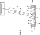
- an ultrasonic horn 90 (e.g., a sonotrode) used for the ultrasonic welding is arranged with the respective rib flange 74, 76.
- a tip 92 of the ultrasonic horn 90 of FIGS. 11 and 12 is positioned over the respective rib flange 74, 76.
- the ultrasonic horn 90 and its tip 92 also engage (e.g., contact) the respective rib flange 74, 76.
- the ultrasonic horn 90 of FIGS. 11 and 12 extends vertically along a centerline 94 of the ultrasonic horn 90 in a direction towards the respective rib flange 74, 76 to the horn tip 92.
- the horn centerline 94 may be angularly offset from the respective rib flange 74, 76 (and a surface of the respective rib flange 74, 76 contacted by the horn tip 92) by an offset angle 96; e.g., the ultrasonic horn 90 may be a tilted ultrasonic horn.
- This offset angle 96 is selected such that the ultrasonic horn 90 and its horn tip 92 may be inserted (e.g., project) into one or more respective channels 60 and/or 80, while a base of the ultrasonic horn 90 remains external to the members 40 and 42 being welded.
- the offset angle 96 is a non-zero acute angle; e.g., between forty-five degrees (45°) and sixty degrees (60°), between sixty degrees (60°) and seventy-five degrees (75°), or between seventy-five degrees (75°) and less than ninety degrees ( ⁇ 90°).
- ⁇ 90° ninety degrees
- the ultrasonic horn 90 of FIGS. 11 and 12 is coupled to an ultrasonic transducer 98.
- This ultrasonic transducer 98 is configured to move (e.g., translate, oscillate, etc.) the ultrasonic horn 90 back-and-forth (e.g., up-and-down) along the horn centerline 94 to ultrasonic weld the respective members 40 and 42 together.
- Oscillating forces e.g., pressing and releasing
- from this movement of the ultrasonic horn 90 are transferred into the stacked members (e.g., 56 and 74, 58 and 76) and heat the thermoplastic matrix 86 (see FIG.
- the members e.g., 56 and 74, 58 and 76
- the heating softens and then locally melts the thermoplastic matrix 86 and thereby welds the members (e.g., 56 and 74, 58 and 76) together at and about a point aligned with the ultrasonic horn 90 and its horn tip 92.
- This ultrasonic welding process may be repeated one or more times for each rib flange 74, 76.
- Each rib flange 74, 76 of FIGS. 11 and 12 may thereby be connected to the respective thermoplastic spar 40 by one or more ultrasonic spot welds.
- the ultrasonic horn 90 may alternatively be translated to provide an ultrasonic weld seam.
- each thermoplastic skin 36, 38 is ultrasonic welded to the thermoplastic frame 34.
- Each thermoplastic skin 36, 38 for example, is arranged adjacent a respective side of the thermoplastic frame 34. That thermoplastic frame 34 may then be ultrasonic welded to the thermoplastic frame 34 using the ultrasonic horn 90 or another ultrasonic horn (e.g., one which may be perpendicular to the respective thermoplastic skin 36, 38).
Landscapes
- Engineering & Computer Science (AREA)
- Mechanical Engineering (AREA)
- Aviation & Aerospace Engineering (AREA)
- Manufacturing & Machinery (AREA)
- Transportation (AREA)
- Lining Or Joining Of Plastics Or The Like (AREA)
Applications Claiming Priority (1)
| Application Number | Priority Date | Filing Date | Title |
|---|---|---|---|
| US18/227,685 US12351305B2 (en) | 2023-07-28 | 2023-07-28 | Thermoplastic composite structure and methods for forming |
Publications (1)
| Publication Number | Publication Date |
|---|---|
| EP4501596A1 true EP4501596A1 (de) | 2025-02-05 |
Family
ID=92106959
Family Applications (1)
| Application Number | Title | Priority Date | Filing Date |
|---|---|---|---|
| EP24191282.3A Pending EP4501596A1 (de) | 2023-07-28 | 2024-07-26 | Thermoplastische verbundstruktur und verfahren zur formung |
Country Status (2)
| Country | Link |
|---|---|
| US (1) | US12351305B2 (de) |
| EP (1) | EP4501596A1 (de) |
Citations (1)
| Publication number | Priority date | Publication date | Assignee | Title |
|---|---|---|---|---|
| DE102016210086A1 (de) * | 2016-06-08 | 2017-12-14 | Airbus Operations Gmbh | Verfahren zum Herstellen eines Strukturbauteils für ein Luft- oder Raumfahrzeug, sowie Anordnung |
Family Cites Families (7)
| Publication number | Priority date | Publication date | Assignee | Title |
|---|---|---|---|---|
| US4481703A (en) * | 1980-02-25 | 1984-11-13 | Rockwell International Corporation | Method of making rib structures for an airfoil |
| US7575194B2 (en) | 2006-11-30 | 2009-08-18 | The Boeing Company | Apparatuses and methods for joining composite members and other structural members in aircraft wing boxes and other structures |
| US10589837B2 (en) | 2016-02-08 | 2020-03-17 | Bell Helicopter Textron Inc. | Spar for a composite wing structure |
| US20170259521A1 (en) * | 2016-02-08 | 2017-09-14 | Bell Helicopter Textron Inc. | Large Cell Core Stiffened Panels with Solid Inserts |
| EP3778196A4 (de) * | 2018-04-13 | 2021-06-02 | Seidensha Electronics Co., Ltd. | Ultraschallschweissverfahren, durch ultraschallschweissverfahren geschweisste struktur und ultraschallschweissvorrichtung |
| US11643184B2 (en) * | 2020-07-29 | 2023-05-09 | The Boeing Company | Wing assembly having discretely stiffened composite wing panels |
| US12552515B2 (en) * | 2021-11-19 | 2026-02-17 | Aurora Flight Sciences Corporation, a subsidiary of The Boeing Company | Aerospace component joints for aircraft and related methods |
-
2023
- 2023-07-28 US US18/227,685 patent/US12351305B2/en active Active
-
2024
- 2024-07-26 EP EP24191282.3A patent/EP4501596A1/de active Pending
Patent Citations (1)
| Publication number | Priority date | Publication date | Assignee | Title |
|---|---|---|---|---|
| DE102016210086A1 (de) * | 2016-06-08 | 2017-12-14 | Airbus Operations Gmbh | Verfahren zum Herstellen eines Strukturbauteils für ein Luft- oder Raumfahrzeug, sowie Anordnung |
Non-Patent Citations (1)
| Title |
|---|
| GINGER GARDINER: "Welding thermoplastic composites", COMPOSITES WORLD, vol. September 2018, 30 September 2018 (2018-09-30), pages 50 - 63, XP055588719 * |
Also Published As
| Publication number | Publication date |
|---|---|
| US12351305B2 (en) | 2025-07-08 |
| US20250033756A1 (en) | 2025-01-30 |
Similar Documents
| Publication | Publication Date | Title |
|---|---|---|
| EP3293104B1 (de) | Versteifungselement mit offenem kanal | |
| KR102474791B1 (ko) | 라미네이트 복합재 날개 구조물 | |
| US8973871B2 (en) | Box structures for carrying loads and methods of making the same | |
| US9370921B2 (en) | Composite radius fillers and methods of forming the same | |
| US10457378B2 (en) | Mechanically Joining airframe members at solid insert | |
| EP3858584B1 (de) | Systeme und verfahren für thermoplastische verbundplatten | |
| US11161592B2 (en) | Torque box sleeves for aircraft wing assemblies | |
| CN103979099A (zh) | 制造具有带短切纤维材料的间隙填充物的复合结构的方法和系统 | |
| US10450054B2 (en) | Adhesively joining airframe members at solid insert | |
| EP2759470A2 (de) | Kastenstruktur zum tragen von lasten und ihren herstellungsverfahren | |
| EP4501596A1 (de) | Thermoplastische verbundstruktur und verfahren zur formung | |
| US20170259521A1 (en) | Large Cell Core Stiffened Panels with Solid Inserts | |
| EP4209334B1 (de) | Vibrationsschweisssystem und -verfahren | |
| EP3357807B1 (de) | Haftverbindung von flugwerkelementen an massiven einsätzen | |
| EP4215344B1 (de) | Vibrationsschweissen von faserverstärkten flugzeugverbundstrukturen | |
| EP4497578A1 (de) | Horizontales ultraschallschweissen von thermoplastischem material | |
| CN116605412A (zh) | 具有流动通道的燃料箱纵梁 | |
| US20250312981A1 (en) | Continuous ultrasonic welding thermoplastic material for aerospace component repair | |
| US20230060367A1 (en) | Thermoplastic composite panel with corrugated peaks and troughs stiffening systems and methods | |
| EP3599089B1 (de) | Kernstrukturen für verbundplatten, flugzeug damit und zugehörige verfahren | |
| EP4585401A1 (de) | Schweissen von thermoplastischem verbundstoff und wabenkern | |
| US12617164B2 (en) | Delamination and edge damage repair on thermoplastic composites | |
| US20250222666A1 (en) | Delamination and edge damage repair on thermoplastic composites | |
| Van Tooren et al. | Composite materials, composite structures, composite systems | |
| US12014712B2 (en) | Corrugated acoustic stiffening devices and methods |
Legal Events
| Date | Code | Title | Description |
|---|---|---|---|
| PUAI | Public reference made under article 153(3) epc to a published international application that has entered the european phase |
Free format text: ORIGINAL CODE: 0009012 |
|
| STAA | Information on the status of an ep patent application or granted ep patent |
Free format text: STATUS: THE APPLICATION HAS BEEN PUBLISHED |
|
| AK | Designated contracting states |
Kind code of ref document: A1 Designated state(s): AL AT BE BG CH CY CZ DE DK EE ES FI FR GB GR HR HU IE IS IT LI LT LU LV MC ME MK MT NL NO PL PT RO RS SE SI SK SM TR |
|
| STAA | Information on the status of an ep patent application or granted ep patent |
Free format text: STATUS: REQUEST FOR EXAMINATION WAS MADE |
|
| 17P | Request for examination filed |
Effective date: 20250805 |