EP4501540A1 - Polishing device, polishing method, and machine component - Google Patents
Polishing device, polishing method, and machine component Download PDFInfo
- Publication number
- EP4501540A1 EP4501540A1 EP23779143.9A EP23779143A EP4501540A1 EP 4501540 A1 EP4501540 A1 EP 4501540A1 EP 23779143 A EP23779143 A EP 23779143A EP 4501540 A1 EP4501540 A1 EP 4501540A1
- Authority
- EP
- European Patent Office
- Prior art keywords
- polishing
- polished
- tool
- drive unit
- circular
- Prior art date
- Legal status (The legal status is an assumption and is not a legal conclusion. Google has not performed a legal analysis and makes no representation as to the accuracy of the status listed.)
- Pending
Links
Images




Classifications
-
- B—PERFORMING OPERATIONS; TRANSPORTING
- B24—GRINDING; POLISHING
- B24B—MACHINES, DEVICES, OR PROCESSES FOR GRINDING OR POLISHING; DRESSING OR CONDITIONING OF ABRADING SURFACES; FEEDING OF GRINDING, POLISHING, OR LAPPING AGENTS
- B24B37/00—Lapping machines or devices; Accessories
- B24B37/04—Lapping machines or devices; Accessories designed for working plane surfaces
- B24B37/042—Lapping machines or devices; Accessories designed for working plane surfaces operating processes therefor
-
- B—PERFORMING OPERATIONS; TRANSPORTING
- B24—GRINDING; POLISHING
- B24B—MACHINES, DEVICES, OR PROCESSES FOR GRINDING OR POLISHING; DRESSING OR CONDITIONING OF ABRADING SURFACES; FEEDING OF GRINDING, POLISHING, OR LAPPING AGENTS
- B24B9/00—Machines or devices designed for grinding edges or bevels on work or for removing burrs; Accessories therefor
- B24B9/02—Machines or devices designed for grinding edges or bevels on work or for removing burrs; Accessories therefor characterised by a special design with respect to properties of materials specific to articles to be ground
- B24B9/06—Machines or devices designed for grinding edges or bevels on work or for removing burrs; Accessories therefor characterised by a special design with respect to properties of materials specific to articles to be ground of non-metallic inorganic material, e.g. stone, ceramics, porcelain
- B24B9/065—Machines or devices designed for grinding edges or bevels on work or for removing burrs; Accessories therefor characterised by a special design with respect to properties of materials specific to articles to be ground of non-metallic inorganic material, e.g. stone, ceramics, porcelain of thin, brittle parts, e.g. semiconductors, wafers
-
- B—PERFORMING OPERATIONS; TRANSPORTING
- B24—GRINDING; POLISHING
- B24B—MACHINES, DEVICES, OR PROCESSES FOR GRINDING OR POLISHING; DRESSING OR CONDITIONING OF ABRADING SURFACES; FEEDING OF GRINDING, POLISHING, OR LAPPING AGENTS
- B24B1/00—Processes of grinding or polishing; Use of auxiliary equipment in connection with such processes
-
- B—PERFORMING OPERATIONS; TRANSPORTING
- B24—GRINDING; POLISHING
- B24B—MACHINES, DEVICES, OR PROCESSES FOR GRINDING OR POLISHING; DRESSING OR CONDITIONING OF ABRADING SURFACES; FEEDING OF GRINDING, POLISHING, OR LAPPING AGENTS
- B24B19/00—Single-purpose machines or devices for particular grinding operations not covered by any other main group
- B24B19/02—Single-purpose machines or devices for particular grinding operations not covered by any other main group for grinding grooves, e.g. on shafts, in casings, in tubes, homokinetic joint elements
-
- B—PERFORMING OPERATIONS; TRANSPORTING
- B24—GRINDING; POLISHING
- B24B—MACHINES, DEVICES, OR PROCESSES FOR GRINDING OR POLISHING; DRESSING OR CONDITIONING OF ABRADING SURFACES; FEEDING OF GRINDING, POLISHING, OR LAPPING AGENTS
- B24B19/00—Single-purpose machines or devices for particular grinding operations not covered by any other main group
- B24B19/02—Single-purpose machines or devices for particular grinding operations not covered by any other main group for grinding grooves, e.g. on shafts, in casings, in tubes, homokinetic joint elements
- B24B19/03—Single-purpose machines or devices for particular grinding operations not covered by any other main group for grinding grooves, e.g. on shafts, in casings, in tubes, homokinetic joint elements for grinding grooves in glass workpieces, e.g. decorative grooves
-
- B—PERFORMING OPERATIONS; TRANSPORTING
- B24—GRINDING; POLISHING
- B24B—MACHINES, DEVICES, OR PROCESSES FOR GRINDING OR POLISHING; DRESSING OR CONDITIONING OF ABRADING SURFACES; FEEDING OF GRINDING, POLISHING, OR LAPPING AGENTS
- B24B27/00—Other grinding machines or devices
- B24B27/0076—Other grinding machines or devices grinding machines comprising two or more grinding tools
-
- B—PERFORMING OPERATIONS; TRANSPORTING
- B24—GRINDING; POLISHING
- B24B—MACHINES, DEVICES, OR PROCESSES FOR GRINDING OR POLISHING; DRESSING OR CONDITIONING OF ABRADING SURFACES; FEEDING OF GRINDING, POLISHING, OR LAPPING AGENTS
- B24B29/00—Machines or devices for polishing surfaces on work by means of tools made of soft or flexible material with or without the application of solid or liquid polishing agents
-
- B—PERFORMING OPERATIONS; TRANSPORTING
- B24—GRINDING; POLISHING
- B24B—MACHINES, DEVICES, OR PROCESSES FOR GRINDING OR POLISHING; DRESSING OR CONDITIONING OF ABRADING SURFACES; FEEDING OF GRINDING, POLISHING, OR LAPPING AGENTS
- B24B29/00—Machines or devices for polishing surfaces on work by means of tools made of soft or flexible material with or without the application of solid or liquid polishing agents
- B24B29/005—Machines or devices for polishing surfaces on work by means of tools made of soft or flexible material with or without the application of solid or liquid polishing agents using brushes
-
- B—PERFORMING OPERATIONS; TRANSPORTING
- B24—GRINDING; POLISHING
- B24B—MACHINES, DEVICES, OR PROCESSES FOR GRINDING OR POLISHING; DRESSING OR CONDITIONING OF ABRADING SURFACES; FEEDING OF GRINDING, POLISHING, OR LAPPING AGENTS
- B24B41/00—Component parts such as frames, beds, carriages, headstocks
- B24B41/04—Headstocks; Working-spindles; Features relating thereto
-
- B—PERFORMING OPERATIONS; TRANSPORTING
- B24—GRINDING; POLISHING
- B24B—MACHINES, DEVICES, OR PROCESSES FOR GRINDING OR POLISHING; DRESSING OR CONDITIONING OF ABRADING SURFACES; FEEDING OF GRINDING, POLISHING, OR LAPPING AGENTS
- B24B47/00—Drives or gearings; Equipment therefor
- B24B47/10—Drives or gearings; Equipment therefor for rotating or reciprocating working-spindles carrying grinding wheels or workpieces
- B24B47/12—Drives or gearings; Equipment therefor for rotating or reciprocating working-spindles carrying grinding wheels or workpieces by mechanical gearing or electric power
Definitions
- An embodiment of the present disclosure relates to a polishing device, a polishing method, and a machine component.
- Patent Literature 1 discloses a cutting method for cutting a workpiece using a spring-necked cutting tool.
- Patent Literature 1 Japanese laid-open patent publication No. H06-126520.
- a groove arranged in the sealing part is usually formed by cutting a sealing surface using a rotary cutting tool such as an end mill. After a desired shape of the groove has been cut, slight unevenness or cutting debris may remain on the sealing surface, and polishing is necessary to remove them. Although the polishing of the sealing surface is often performed manually by a worker, it takes a long time to complete the polishing process, and there is a problem that the quality of the sealing surface is not stabilized due to a difference in a surface roughness of the polishing surface depending on the experience and skill of the worker.
- an object of an embodiment of the present disclosure is to provide a polishing device and a polishing method capable of reducing the time required for polishing and stabilizing the quality of the sealing surface.
- a polishing device includes a supporting unit supporting a polishing tool, a stage holding an object to be polished, a first drive unit moving the supporting unit and the stage relative to each other along a shape of a polished surface, and a second drive unit synchronized with the first drive unit and rotating the supporting unit so that one end of a polishing member attached to the polishing tool faces in a movement direction.
- a machine component includes a hard anodized aluminum surface, and a polishing surface on a part of the hard anodized aluminum surface, wherein a waviness of the polishing surface is 0.2 ⁇ m or less and a surface roughness of the polishing surface is 0.4 ⁇ m or less.
- the time required for polishing can be reduced and the quality of a sealing surface can be stabilized.
- a member or region in the case where a member or region is "above (or below)" another member or region, it includes the case where it is directly above (or below) the other member or region, but also the case where it is above (or below) the other member or region, that is, the case where another component is included between above (or below) the other member or region.
- the configuration of the first drive unit 105 is not limited to the above.
- the first drive unit 105 may further include a moving mechanism for moving the supporting unit 101 in the direction x and/or the direction y.
- the first drive unit 105 may further include a moving mechanism for moving the stage 103 in the direction z.
- FIG. 3 is a schematic view showing an example of a polishing tool 201A used in the first step in the polishing process.
- the polishing tool 201A includes a jig 303 and a first polishing member 305A attached to the jig 303 via a polishing member holding unit 307.
- the first polishing member 305A may be a brush made of ceramic fiber, nylon, or the like.
- the first step in the polishing process is a polishing process using a brush.
- FIG. 4 is a schematic view showing an example of a polishing tool 201B used in the second step of the polishing process.
- the polishing tool 201B has substantially the same configuration as the polishing tool 201A shown in FIG. 3 and FIG. 6 , except that the material of a second polishing member 305B attached to the jig 303 is different from the material of the first polishing member 305A, and the coil spring 315 inside the jig 303 has a different spring constant than the coil spring 315 inserted inside the jig 303 of the polishing tool 201A shown in FIG. 3 and FIG. 6 .
- the second polishing member 305B is a sponge polishing agent coated with abrasive grains such as aluminum oxide, titanium oxide, or zircon.
- the second step in the polishing process is a polishing process using a sponge.
- the polishing member 305 may be cylindrical.
- a spring constant of the coil spring 315 inserted into the jig 303 of the polishing tool 201B is different from the spring constant of the coil spring 315 inserted into the jig 303 of the polishing tool 201A used in the first step.
- the spring constant of the coil spring 315 inserted into the jig 303 of the polishing tool 201B is greater than 1N/mm and 10N/mm or less.
- the spring constant of the coil spring 315 inserted into the jig 303 of the polishing tool 201B is greater than the spring constant of the coil spring 315 inserted into the jig 303 of the polishing tool 201A.
- a worker engaged in the polishing process performed by the polishing device 10 may remove the polishing tool 201A from the supporting unit 101 of the polishing device 10 and attach the polishing tool 201B to the supporting unit 101 after the first step using the polishing tool 201A is completed.
- the worker may disassemble the jig 303 of the polishing tool 201A, take out the coil spring 315 with a spring constant of 1N/mm or more and 5N/mm or less from the polishing tool 201A used in the first step, and replace it with the coil spring 315 with a spring constant greater than 1N/mm and 10N/mm or less used in the second step, thereby producing the polishing tool 201B.
- the worker may replace the coil spring 315 of the jig 303, remove the first polishing member 305A attached to the polishing tool 201A, and removably attach the second polishing member 305B.
- a material of the second polishing member 305C of the polishing tool 201C is the same as the material of the second polishing member 305B of the polishing tool 201B.
- the shape of the second polishing member 305C may be different from that of the second polishing member 305B, for example, hemispherical.
- the worker may disassemble the jig 303 of the polishing tool 201A, take out the coil spring 315 with a spring constant of 1N/mm or more and 5N/mm or less from the polishing tool 201A used in the first step, replace the coil spring 315 with a spring constant greater than 1N/mm and 10N/mm or less used in the second step, and removably attach the second polishing member 305C by removing the first polishing member 305A attached to the polishing tool 201A, thereby producing the polishing tool 201C.
- the polishing tool 201B shown in FIG. 4 and the polishing tool 201C shown in FIG. 5 can be used in the second step of the polishing process performed by the polishing device 10.
- the polishing tool 201B shown in FIG. 4 is preferably used in the case where the polishing surface of the object to be polished 203 is circular.
- the polishing tool 201C is preferably used in the case where the polishing surface of the object to be polished 203 is non-circular.
- Aluminum alloy A6061 with dimensions: ⁇ 360mm ⁇ t40mm is prepared as the object to be polished, subjected to hard anodizing on the surface, and a hard anodized coating with a thickness of 80 ⁇ m is formed.
- the aluminum alloy A6061 on which the hard anodized coating was formed on the surface was used as the object to be polished, and the surface on which the hard anodized coating was formed was polished by the polishing device according to the present embodiment.
- the polishing surface of the object to be polished was the same as the polishing surface of the object to be polished 203 shown in FIG. 7 .
- a Robodrill manufactured by FANUC Corporation was used as the polishing device, and a float holder (FH-ST12-SL10) manufactured by XEBEC CO., LTD. was used as the jig of the polishing tool.
- a polishing tool (hereinafter referred to as a first polishing tool) manufactured by inserting a coil spring (WL10-35, spring constant: 1N/mm) manufactured by MISUMI CO., LTD. into the inside of the jig and attaching a brush (A11-EB06M) manufactured by XBEC CO., LTD. with a brush length adjusted to 12mm to the jig was used.
- a coil spring (WL10-35, spring constant: 1N/mm) manufactured by MISUMI CO., LTD.
- a brush (A11-EB06M) manufactured by XBEC CO., LTD. with a brush length adjusted to 12mm to the jig was used.
- second polishing tool A a polishing tool manufactured by inserting a coil spring (WT10-35, spring constant: 2N/mm) manufactured by MISUMI CO., LTD. into the inside of the jig
- a sponge polishing agent (Super Fine) manufactured by 3M Company was cut out in a cylindrical shape with the diameter of 21mm and the thickness of 5mm, and attached to the jig.
- a polishing tool (hereinafter referred to as a second polishing tool B) manufactured by inserting a coil spring (WT10-35, spring constant: 2N/mm) manufactured by MISUMI CO., LTD. into the inside of the jig was used, the sponge polishing agent (Super Fine) manufactured by 3M Company was cut out with a width of 6mm and a length of40 mm, the tip was processed to have a hemispherical shape with a diameter of 5mm, and attached to the jig.
- a coil spring WT10-35, spring constant: 2N/mm
- the sponge polishing agent Super Fine
- the feed speed was set to 2000/min of the second polishing tool B at the R portion, and the feed speed was set to 4000/min at the linear portion, the second polishing tool B was lowered to the helical Z: -1.0mm, the polishing surface 705a and the polishing surface 705b were polished 20 times, respectively, and the polishing surface 705c was polished 10 times, constituting one set, and six sets were carried out.
- the circular polishing surfaces 703a to 703j and the non-circular polishing surfaces 705a to 705c in the same object to be polished as the object to be polished used in Example 1 were manually polished by the worker.
- the manual polishing process is as follows.
- a surface roughness (Ra) of the polishing surface after carrying out the polishing process and working hours described in Example 1 are shown in the following Table 1.
- the surface roughness (Ra) of the polishing surface after carrying out the polishing process of Comparative Example 1 and working hours are shown in the following Table 2.
- Comparing Example 1 and Comparative Example 1 it can be seen that polishing by the polishing device according to the present embodiment can obtain a better result than or substantially the same result as polishing by a manual operation, while significantly reducing the time required for the polishing process than polishing by the manual operation. Furthermore, in Example 1, it can be seen that the difference in surface roughness depending on the polishing position is smaller than that in Comparative Example 1, and the quality of the sealing surface can be stabilized.
- the circular polishing surfaces 703a, 703e, and 703j and the non-circular polishing surfaces 705a to 705c were polished by a polishing process substantially the same as in Example 1.
- the sponge was replaced after one cycle was complete, and the process was carried out for three cycles, respectively.
- Table 3 shows the waviness and surface roughness of the circular polishing surfaces 703a, 703e, and 703j after the polishing process according to Example 2, and Table 4 shows the waviness and surface roughness of the non-circular polishing surfaces 705a to 705c after the polishing process according to Example 2.
- the cut-off value for separating the waviness and the surface roughness was set to 200 ⁇ m.
- Polishing surface Waviness (Wa[ ⁇ m]) Standard deviation of waviness (Wq[ ⁇ m]) Surface roughness (Arithmetic mean roughness) Standard deviation of surface roughness (Sq[ ⁇ m]) (Sa[ ⁇ m]) 703a 0.062 0.079 0.193 0.262 703e 0.061 0.074 0.155 0.208 703j 0.071 0.083 0.115 0.150 Average 0.066 0.079 0.155 0.207
- Polishing surface Waviness (Wa[ ⁇ m]) Standard deviation of waviness (Wq[ ⁇ m])
- a masking seal exposing the circular polishing surfaces 703a, 703e, and 703j and the non-circular polishing surfaces 705a to 705c of the object to be polished was adhered to the sealing surface 701 of the object to be polished.
- the reinforcement gabarit was adhered to the masking seal.
- a Sulclut manufactured by Kyodo Yushi
- each of the polishing surfaces 703a, 703e, 703j and 705a to 705c was manually polished for 1.5 hours using the sponge polishing agent (Super Fine) manufactured by 3M Company. After that, each of the polishing surfaces 703a, 703e, 703j and 705a to 705c was wiped with a clean wiper with NEI clean 2, and the masking seal was peeled off from the polished surface 701.
- the sponge polishing agent Super Fine
- the embodiment of the present disclosure is not limited to the above-described embodiment.
- a modification of the polishing process performed by the polishing device of the present disclosure will be described.
- the polishing process of the first step using a brush as the polishing member may include a pre-process of performing roughing and a post-process of performing finishing.
- springs with different spring constants are inserted into the jig of the polishing tool in the pre-process and the post-process, and the pressing strength applied to the polishing tool used in the pre-process and the pressing strength applied to the polishing tool used in the post-process are changed.
- the pressing strength of the polishing tool used in the pre-process is preferably greater than the pressing strength of the polishing tool used in the post-process.
- the spring constant of the spring inserted into the jig of the polishing tool used in the pre-process is preferably higher than the spring constant of the spring inserted into the jig of the polishing tool used in the post-process.
Landscapes
- Engineering & Computer Science (AREA)
- Mechanical Engineering (AREA)
- Chemical & Material Sciences (AREA)
- Ceramic Engineering (AREA)
- Inorganic Chemistry (AREA)
- Finish Polishing, Edge Sharpening, And Grinding By Specific Grinding Devices (AREA)
- Grinding And Polishing Of Tertiary Curved Surfaces And Surfaces With Complex Shapes (AREA)
- Constituent Portions Of Griding Lathes, Driving, Sensing And Control (AREA)
- Grinding Of Cylindrical And Plane Surfaces (AREA)
- Grinding-Machine Dressing And Accessory Apparatuses (AREA)
Abstract
Description
- An embodiment of the present disclosure relates to a polishing device, a polishing method, and a machine component.
- In a manufacturing process of various electronic components such as a semiconductor device and a display panel for a display device, the process is performed in a vacuum. In such a vacuum process, a vacuum vessel is used, and a groove is provided on one or both of the contacting parts where the parts of the vacuum vessel come into contact with each other, and a sealing member such as an O-ring is installed in the grooves in order to ensure the inside of the vessel is sealed. Patent Literature 1 discloses a cutting method for cutting a workpiece using a spring-necked cutting tool.
- Patent Literature 1:
Japanese laid-open patent publication No. H06-126520. - A groove arranged in the sealing part is usually formed by cutting a sealing surface using a rotary cutting tool such as an end mill. After a desired shape of the groove has been cut, slight unevenness or cutting debris may remain on the sealing surface, and polishing is necessary to remove them. Although the polishing of the sealing surface is often performed manually by a worker, it takes a long time to complete the polishing process, and there is a problem that the quality of the sealing surface is not stabilized due to a difference in a surface roughness of the polishing surface depending on the experience and skill of the worker.
- In view of the above problem, an object of an embodiment of the present disclosure is to provide a polishing device and a polishing method capable of reducing the time required for polishing and stabilizing the quality of the sealing surface.
- In addition, an object of an embodiment of the present disclosure is to provide a machine component having a sealing surface with stabilized quality.
- A polishing device according to an embodiment of the present disclosure includes a supporting unit supporting a polishing tool, a stage holding an object to be polished, a first drive unit moving the supporting unit and the stage relative to each other along a shape of a polished surface, and a second drive unit synchronized with the first drive unit and rotating the supporting unit so that one end of a polishing member attached to the polishing tool faces in a movement direction.
- A polishing method according to an embodiment of the present disclosure is a polishing method for a polishing surface on a hard anodized aluminum, the polishing method including a first step of polishing the polishing surface with a first polishing member at a first pressing strength, and a second step of polishing the polishing surface with a second polishing member at a second pressing strength after the first step, wherein the first pressing strength is lower than the second pressing strength.
- A machine component according to an embodiment of the present disclosure includes a hard anodized aluminum surface, and a polishing surface on a part of the hard anodized aluminum surface, wherein a waviness of the polishing surface is 0.2µm or less and a surface roughness of the polishing surface is 0.4µm or less.
- According to an embodiment of the present disclosure, by automating a polishing process with a machine, the time required for polishing can be reduced and the quality of a sealing surface can be stabilized.
-
-
FIG. 1 is a diagram for explaining an example of a configuration of a polishing device according to an embodiment of the present disclosure. -
FIG. 2 is a functional block diagram of a polishing device according to an embodiment. -
FIG. 3 is a schematic view showing an example of a polishing tool used in a polishing device according to an embodiment. -
FIG. 4 is a schematic view showing an example of a polishing tool used in a polishing device according to an embodiment. -
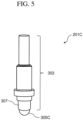
FIG. 5 is a schematic view showing an example of a polishing tool used in a polishing device according to an embodiment. -
FIG. 6 is a schematic exploded view of a jig of a polishing tool used in a polishing device according to an embodiment. -
FIG. 7 is a plan view of an example of an object to be polished viewed from above. -
FIG. 8 is a schematic view for explaining a moving route of a second polishing member when polishing a non-circular polishing surface of an object to be polished. - Hereinafter, embodiments of the present disclosure will be described with reference to the drawings and the like. However, the present invention can be implemented in many different aspects, and should not be construed as being limited to the description of the embodiments exemplified below. In order to make the description clearer, the drawings may be schematically represented with respect to the width, thickness, shape, and the like of each part as compared with the actual embodiment, but the drawings are merely examples, and do not limit the interpretation of the present disclosure.
- In the drawings, the widths, thicknesses, shapes, and the like of the respective portions may be schematically represented in comparison with the actual embodiments for clarity of explanation, but the drawings are merely examples, and do not limit the interpretation of the present invention. Furthermore, in the present specification and the drawings, elements having the same functions as those described with respect to the above-described drawings are denoted by the same reference signs, and redundant descriptions thereof may be omitted. Furthermore, in the present specification and the drawings, the same or similar parts are denoted by the same reference signs or similar reference signs (reference signs denoted by A, B, and the like after numerals) and repeated description thereof may be omitted.
- In the present specification, in the case where a member or region is "above (or below)" another member or region, it includes the case where it is directly above (or below) the other member or region, but also the case where it is above (or below) the other member or region, that is, the case where another component is included between above (or below) the other member or region.
- Furthermore, in the present specification, the expressions "α includes A, B or C," "α includes any of A, B and C," and "α includes one selected from a group consisting of A, B, and C" do not exclude the case where α includes a plurality of combinations of A to C unless otherwise specified. Furthermore, these expressions do not exclude the case where α includes other elements.
- Hereinafter, a
polishing device 10 according to an embodiment of the present disclosure will be described with reference to the drawings. -
FIG. 1 is a diagram for explaining an example of a configuration of thepolishing device 10 according to an embodiment of the present disclosure. As shown inFIG. 1 , thepolishing device 10 includes a supportingunit 101, astage 103, afirst drive unit 105, and asecond drive unit 107. - The supporting
unit 101 supports apolishing tool 201. Thepolishing tool 201 will be described later. The supportingunit 101 is attached to thefirst drive unit 105. - The
stage 103 holds an object to be polished 203. The object to be polished 203 is part of a machine component. The object to be polished 203 is not particularly limited, but may be, for example, a part constituting vacuum equipment used in a vacuum device. In this case, the object to be polished 203 includes a sealing surface of a vacuum vessel. For example, the sealing surface may be subjected to hard anodizing. Thepolishing tool 201 can polish a hard anodized coating of the object to be polished 203. In the present embodiment, a coating formed on the object to be polished 203 is not limited to hard anodized aluminum. For example, the hardness of a surface of the object to be polished 203 is about Hv 350 to 450. - The
first drive unit 105 relatively moves the supportingunit 101 and thestage 103 along a shape of a polishing surface of the object to be polished 203. In other words, thefirst drive unit 105 includes a mechanism for moving the position of one or both of the supportingunit 101 and thestage 103 such that thepolishing tool 201 is movable along the shape of the polishing surface. Thefirst drive unit 105 includes a first movingunit 109, afirst guide 111, asecond guide 113, a second movingunit 115, and athird guide 117. - The first moving
unit 109 moves the supportingunit 101 along a direction z. Thefirst guide 111 is arranged on abody 119 of thepolishing device 10 so as to extend in the direction z. Thefirst guide 111 guides a movement of the first movingunit 109 in the direction z. For example, thefirst guide 111 may be a rail extending in the direction z, and the first movingunit 109 may slide along thefirst guide 111 in the direction z. The first movingunit 109 and thefirst guide 111 constitute afirst moving mechanism 112 that moves the supportingunit 101. - The
second guide 113 guides a movement of thestage 103 in the direction x. Thesecond guide 113 may be a rectangular plate having a pair of sides along the direction x and a pair of sides along a direction y. Thestage 103 is slidably supported in the direction x by thesecond guide 113. For example, thestage 103 may be arranged so as to sandwich an edge of the pair of sides along the direction x of thesecond guide 113, and may slide along the edge of the pair of sides along the direction x of theguide 113. - The second moving
unit 115 moves thesecond guide 113 that supports thestage 103 along the direction y. Thethird guide 117 is arranged on thebody 119 of the polishingdevice 10 so as to extend in the direction y. Thethird guide 117 guides a movement of thesecond guide 113 in the direction y. For example, thethird guide 117 may be a rail extending in the direction y, and thesecond guide 113 may slide in the direction y along thethird guide 117. - The
second guide 113, the second movingunit 115, and thethird guide 117 may constitute asecond moving mechanism 118 that moves thestage 103. - Although an example of the configuration of the
first drive unit 105 has been described, in the present embodiment, the configuration of thefirst drive unit 105 is not limited to the above. For example, thefirst drive unit 105 may further include a moving mechanism for moving the supportingunit 101 in the direction x and/or the direction y. In addition, thefirst drive unit 105 may further include a moving mechanism for moving thestage 103 in the direction z. - The
second drive unit 107 rotates the supportingunit 101 that supports thepolishing tool 201. In addition, thesecond drive unit 107 may rotate the supportingunit 101 in synchronization with thefirst drive unit 105 such that one end of the polishing member attached to thepolishing tool 201 constantly faces in the movement direction of thepolishing tool 201 along the polishing surface of the object to be polished 203. - Although not shown, the polishing
device 10 includes a plurality of motors. These motors cause thefirst drive unit 105 and thesecond drive unit 107 to move and rotate the supportingunit 101 and thestage 103. -
FIG. 2 is an example of a functional block diagram of the polishingdevice 10. As shown inFIG. 2 , the polishingdevice 10 includes aninput operation unit 121 and acontroller 122. - The
input operation unit 121 is a device such as an operation panel, an operation button, and a touch panel, and outputs a signal corresponding to the input operation to thecontroller 122. A worker engaged in the polishing operation may control an operation of thefirst drive unit 105 and thesecond drive unit 107 of the polishingdevice 10 via theinput operation unit 121. For example, the worker can set or change the start and stop of the polishing process performed by the polishingdevice 10, the rotating speed of the supportingunit 101, the moving speed and the movement direction to the supportingunit 101 and thestage 103 via theinput operation unit 121. - The
controller 122 includes a calculation processing circuit, such as a CPU, and a storage. Thecontroller 122 executes a control program stored in the storage by the CPU to control the operations of thefirst drive unit 105 and thesecond drive unit 107, and realizes a polishing function by the polishingdevice 10. -
FIG. 3 ,FIG. 4 , andFIG. 5 are schematic views showing an example of thepolishing tool 201 supported by the supportingunit 101 of the polishingdevice 10 according to the present embodiment. - The polishing process of the object to be polished 203 performed by the polishing
device 10 according to the present embodiment includes a first step of polishing the polishing surface with a first polishing member at a first pressing strength, and a second step of polishing the polishing surface with a second polishing member at a second pressing strength after the first step. The first polishing member and the second polishing member are made of different materials. In addition, the first pressing strength and the second pressing strength are different from each other. In this case, the pressing strength means a load applied to a polishing jig when the polishing member contacts a surface to be polished of the object to be polished 203 in the polishing process. -
FIG. 3 is a schematic view showing an example of apolishing tool 201A used in the first step in the polishing process. Thepolishing tool 201A includes ajig 303 and afirst polishing member 305A attached to thejig 303 via a polishingmember holding unit 307. For example, thefirst polishing member 305A may be a brush made of ceramic fiber, nylon, or the like. In other words, the first step in the polishing process is a polishing process using a brush. -
FIG. 6 is an example of a schematic exploded view of thejig 303. As shown inFIG. 3 andFIG. 6 , thejig 303 includes the polishingmember holding unit 307, afixture 309, aholder 311, and acover 313. - The
fixture 309 is fixed to the supportingunit 101 of the polishingdevice 10. Theholder 311 is joined to thefixture 309. Ahollow storage area 312 is arranged inside theholder 311, and acoil spring 315 is inserted into thestorage area 312. A spring constant of thecoil spring 315 of thepolishing tool 201A used in the first step is 1N/mm or more and 5N/mm or less. A float mechanism is formed by a coil spring 305 inserted into thejig 303. - The polishing
member holding unit 307 is inserted into and fixed to thestorage area 312 of thefixture 309. The polishingmember holding unit 307 is inserted into thestorage area 312 so as to compress thecoil spring 315 via awasher 316. At this time, the polishingmember holding unit 307 compresses thecoil spring 315 so that it is not completely adhered. The polishing holdingmember holding unit 307 is provided with a hollow 308. Thefirst polishing member 305A is removably attached to the hollow 308. - A pair of
openings 317 is arranged in theholder 311. Asteel ball 319 is inserted into eachopening 317. Thecover 313 is arranged on theopening 317 so as to close theopening 317 in which thesteel ball 319 is inserted, and is fixed by twosnap rings 321 so that thecover 313 is not displaced. -
FIG. 4 is a schematic view showing an example of apolishing tool 201B used in the second step of the polishing process. Thepolishing tool 201B has substantially the same configuration as thepolishing tool 201A shown inFIG. 3 andFIG. 6 , except that the material of asecond polishing member 305B attached to thejig 303 is different from the material of thefirst polishing member 305A, and thecoil spring 315 inside thejig 303 has a different spring constant than thecoil spring 315 inserted inside thejig 303 of thepolishing tool 201A shown inFIG. 3 andFIG. 6 . - In the
polishing tool 201B shown inFIG. 4 , for example, thesecond polishing member 305B is a sponge polishing agent coated with abrasive grains such as aluminum oxide, titanium oxide, or zircon. In other words, the second step in the polishing process is a polishing process using a sponge. For example, the polishing member 305 may be cylindrical. - A spring constant of the
coil spring 315 inserted into thejig 303 of thepolishing tool 201B is different from the spring constant of thecoil spring 315 inserted into thejig 303 of thepolishing tool 201A used in the first step. The spring constant of thecoil spring 315 inserted into thejig 303 of thepolishing tool 201B is greater than 1N/mm and 10N/mm or less. The spring constant of thecoil spring 315 inserted into thejig 303 of thepolishing tool 201B is greater than the spring constant of thecoil spring 315 inserted into thejig 303 of thepolishing tool 201A. - A worker engaged in the polishing process performed by the polishing
device 10 may remove thepolishing tool 201A from the supportingunit 101 of the polishingdevice 10 and attach thepolishing tool 201B to the supportingunit 101 after the first step using thepolishing tool 201A is completed. In addition, the worker may disassemble thejig 303 of thepolishing tool 201A, take out thecoil spring 315 with a spring constant of 1N/mm or more and 5N/mm or less from thepolishing tool 201A used in the first step, and replace it with thecoil spring 315 with a spring constant greater than 1N/mm and 10N/mm or less used in the second step, thereby producing thepolishing tool 201B. In this case, the worker may replace thecoil spring 315 of thejig 303, remove thefirst polishing member 305A attached to thepolishing tool 201A, and removably attach thesecond polishing member 305B. -
FIG. 5 is a schematic view showing another example of apolishing tool 201C used in the second step of the polishing process. Asecond polishing member 305C attached to thejig 303 of thepolishing tool 201C is another example of a second polishing member that is different from thesecond polishing member 305B shown inFIG. 4 . Thepolishing tool 201C has substantially the same configuration as thepolishing tool 201B shown inFIG. 4 , except that a shape of thesecond polishing member 305C attached to thejig 303 is different from a shape of thesecond polishing member 305B. - A material of the
second polishing member 305C of thepolishing tool 201C is the same as the material of thesecond polishing member 305B of thepolishing tool 201B. On the other hand, the shape of thesecond polishing member 305C may be different from that of thesecond polishing member 305B, for example, hemispherical. - The worker engaged in the polishing process performed by the polishing
device 10 may remove thepolishing tool 201A from the supportingunit 101 of the polishingdevice 10 and attach thepolishing tool 201C to the supportingunit 101 after the first step using thepolishing tool 201A is completed. In addition, the worker may disassemble thejig 303 of thepolishing tool 201A, take out thecoil spring 315 with a spring constant of 1N/mm or more and 5N/mm or less from thepolishing tool 201A used in the first step, replace thecoil spring 315 with a spring constant greater than 1N/mm and 10N/mm or less used in the second step, and removably attach thesecond polishing member 305C by removing thefirst polishing member 305A attached to thepolishing tool 201A, thereby producing thepolishing tool 201C. - The
polishing tool 201B shown inFIG. 4 and thepolishing tool 201C shown inFIG. 5 can be used in the second step of the polishing process performed by the polishingdevice 10. Thepolishing tool 201B shown inFIG. 4 is preferably used in the case where the polishing surface of the object to be polished 203 is circular. On the other hand, thepolishing tool 201C is preferably used in the case where the polishing surface of the object to be polished 203 is non-circular. -
FIG. 7 is a plan view of an example of the object to be polished 203 viewed from above. For example, the object to be polished 203 is a part constituting the vacuum vessel, and is formed of an aluminum alloy, stainless steel, or the like. The object to be polished 203 has a sealingsurface 701. The sealingsurface 701 is subjected to hard anodizing, and a thickness of the hard anodized coating may be about 30µm to about 100µm. The sealingsurface 701 includes a plurality of polishing surfaces. In this case, the polishing surface means a surface on the sealingsurface 701, that is polished by thepolishing tool 201. The polishing surface includescircular polishing surfaces 703a to 703j andnon-circular polishing surfaces 705a to 705c. - When the
circular polishing surfaces 703a to 703j are polished, thepolishing tool 201B shown inFIG. 4 is preferably used in the second step. In the second step, thesecond drive unit 107 of the polishingdevice 10 rotates the supportingunit 101 supporting thepolishing tool 201B at a predetermined rotating speed. In other words, thesecond polishing member 305B of thepolishing tool 201B polishes thecircular polishing surfaces 703a to 703j while rotating at a predetermined rotating speed. - When polishing the
non-circular polishing surfaces 705a to 705c, thepolishing tool 201C shown inFIG. 5 is preferably used in the second step. Thesecond drive unit 107 of the polishingdevice 10 rotates the supportingunit 101 along the shapes of the polishingsurfaces 705a to 705c such that a predetermined end of thesecond polishing member 305C attached to thepolishing tool 201C constantly faces in the direction in which thepolishing tool 201C moves. For example, the predetermined end of thesecond polishing member 305C is part of an outer surface (spherical crown) of the hemisphericalsecond polishing member 305C. -
FIG. 8 is a schematic view for explaining a moving route of thesecond polishing member 305C attached to thepolishing tool 201C when polishing the non-circular polishing surface. InFIG. 8 , thenon-circular polishing surface 705b shown inFIG. 7 is shown as the non-circular polishing surface. Furthermore, inFIG. 8 , the movement direction of thepolishing tool 201C is indicated by a dashed arrow. As shown inFIG. 8 , in the second step, thesecond drive unit 107 rotates the supportingunit 101 such that apredetermined end 801a of thesecond polishing member 305C constantly faces in the movement direction of thepolishing tool 201C along a shape of the polishingsurface 705b. - A surface roughness of the polishing surface of the object to be polished 203, after the polishing process including the first and second steps performed by the polishing
device 10, preferably has a waviness of 0.2µm or less, a standard deviation of the waviness of 0.2µm or less, a surface roughness of 0.4µm or less, and a standard deviation of the surface roughness of 0.3µm or less. The surface roughness of the polishing surface of the object to be polished 203 is more preferably 0.2µm or less. In this case, among the undulations at different intervals arranged on the polishing surface, the larger one is referred to as "waviness". A reference length (cut-off value) defined in JIS B0633 can be used to separate the "waviness" from the "roughness" that is a smaller undulation. - In the present embodiment, the polishing process performed by the polishing
device 10 includes the first step of polishing the polishing surface with the first pressing strength by thefirst polishing member 305A, and the second step of polishing the polishing surface with the second pressing strength by thesecond polishing member 305B or thesecond polishing member 305C after the first step. Since the spring constant of thecoil spring 315 inserted into thejig 303 of thepolishing tool 201A to which thefirst polishing member 305A is attached and the spring constant of thecoil spring 315 inserted into thejig 303 of thepolishing tools second polishing members polishing tool 201A and thepolishing tools - This makes it possible to automate the polishing process with a machine, reduce the time required for polishing, and stabilize the quality of the sealing surface. In addition, the waviness and the surface roughness of the polishing surface can be made smaller than the waviness and the surface roughness of the polishing surface polished by the manual operation of the worker, and airtightness of the sealing surface can be improved.
- In addition, by rotating the supporting
unit 101 by thesecond drive unit 107 so that a predetermined end of thesecond polishing member 305C constantly faces in the movement direction of thepolishing tool 201C, the polishing process can be mechanically automated even when the polishing surface is non-circular. - Aluminum alloy A6061 with dimensions: ϕ360mm × t40mm is prepared as the object to be polished, subjected to hard anodizing on the surface, and a hard anodized coating with a thickness of 80µm is formed. The aluminum alloy A6061 on which the hard anodized coating was formed on the surface was used as the object to be polished, and the surface on which the hard anodized coating was formed was polished by the polishing device according to the present embodiment. The polishing surface of the object to be polished was the same as the polishing surface of the object to be polished 203 shown in
FIG. 7 . A Robodrill manufactured by FANUC Corporation was used as the polishing device, and a float holder (FH-ST12-SL10) manufactured by XEBEC CO., LTD. was used as the jig of the polishing tool. - In the first step of the polishing process performed by the polishing device, a polishing tool (hereinafter referred to as a first polishing tool) manufactured by inserting a coil spring (WL10-35, spring constant: 1N/mm) manufactured by MISUMI CO., LTD. into the inside of the jig and attaching a brush (A11-EB06M) manufactured by XBEC CO., LTD. with a brush length adjusted to 12mm to the jig was used. In addition, when polishing the circular polishing surface in the second step of the polishing process performed by the polishing device, a polishing tool (hereinafter, referred to as second polishing tool A) manufactured by inserting a coil spring (WT10-35, spring constant: 2N/mm) manufactured by MISUMI CO., LTD. into the inside of the jig was used, a sponge polishing agent (Super Fine) manufactured by 3M Company was cut out in a cylindrical shape with the diameter of 21mm and the thickness of 5mm, and attached to the jig. In addition, when polishing the non-circular polishing surface in the second step of the polishing process performed by the polishing device, a polishing tool (hereinafter referred to as a second polishing tool B) manufactured by inserting a coil spring (WT10-35, spring constant: 2N/mm) manufactured by MISUMI CO., LTD. into the inside of the jig was used, the sponge polishing agent (Super Fine) manufactured by 3M Company was cut out with a width of 6mm and a length of40 mm, the tip was processed to have a hemispherical shape with a diameter of 5mm, and attached to the jig.
- In the first step of the polishing process, for each of the 10 circular polishing surfaces of the object to be polished (see the polishing
surfaces 703a to 703j shown inFIG. 7 ), the first polishing tool is moved from helical Z: 2.0mm to Z -1.0mm at a position in the radial 7.5mm with a rotating speed of 5000rpm and a feed speed of 2000mm/min, and each of the circular polishing surfaces was polished 5 times in a circular arc with the radial 7.5mm, shifted by 1.75mm, and then each of the circular polishing surfaces was polished 5 times in a spiral path. After that, for each of the 10 circular polishing surfaces of the object to be polished, the rotating speed of the first polishing tool was changed to 8000rpm, moved from the helical Z 2.0 to Z -1.0 at a position in the radial 7.5mm with the feed speed of 2000mm/min, and each of the circular polishing surfaces was polished 5 times in a circular arc with the radial 7.5mm, shifted by 1.75mm, and then each of the circular polishing surfaces was polished 5 times in the spiral path. - In the second step of the polishing process, for each of the 10 circular polishing surfaces of the object to be polished, the second polishing tool A is lowered to Helical Z: -3.0mm at the rotating speed of 30rpm of the second polishing tool A, and a stop polishing process was performed for 10 seconds, constituting one set, and two sets of this process was carried out.
- In the first step of the polishing process, for each of the three non-circular polishing surfaces of the object to be polished (see the polishing
surfaces 705a to 705c shown inFIG. 7 ), the rotating speed of 5000rpm and the feed speed of 2000mm/min of the first polishing tool were set, the first polishing tool was lowered to the helical Z: -1.0mm, the polishingsurface 705a and the polishingsurface 705b were polished 10 times, and the polishingsurface 705c was polished 5 times, constituting one set, and two sets of this process were carried out for each of the polishingsurface 705a, the polishingsurface 705b, and the polishingsurface 705c. After that, the rotating speed of the first polishing tool was changed to 8000rpm, the first polishing tool was lowered to the helical Z: -0.5mm, the polishingsurface 705a and the polishingsurface 705b were polished 20 times, respectively, and the polishingsurface 705c was polished 10 times, constituting one set, and two sets of this process were carried out for each of the polishingsurface 705a, the polishingsurface 705b, and the polishingsurface 705c. - In the second step of the polishing process, for each of the three non-circular polishing surfaces of the object to be polished (see the polishing
surfaces 705a to 705c shown inFIG. 7 ), the feed speed was set to 2000/min of the second polishing tool B at the R portion, and the feed speed was set to 4000/min at the linear portion, the second polishing tool B was lowered to the helical Z: -1.0mm, the polishingsurface 705a and the polishingsurface 705b were polished 20 times, respectively, and the polishingsurface 705c was polished 10 times, constituting one set, and six sets were carried out. - As Comparative Example 1, the
circular polishing surfaces 703a to 703j and thenon-circular polishing surfaces 705a to 705c in the same object to be polished as the object to be polished used in Example 1 were manually polished by the worker. The manual polishing process is as follows. - First, the same object to be polished as in Example 1 was used as the object to be polished. Similar to Example 1, the polishing surface of the object to be polished was the same as the polishing surface of the object to be polished 203 shown in
FIG. 7 . Next, a masking seal exposing the 10 circular polishing surfaces of the object to be polished (see the polishingsurfaces 703a to 703j shown inFIG. 7 ) and the three non-circular polishing surfaces (see the polishingsurfaces 705a to 705c shown inFIG. 7 ) was adhered to the sealingsurface 701 of the object to be polished. In addition, a reinforcement gabarit was adhered to the masking seal. After that, a Sulclut (manufactured by Kyodo Yushi) was applied to each of the polishingsurfaces 703a to 703j and 705a to 705c, and then each of the polishingsurfaces 703a to 703j and 705a to 705c was manually polished for 1.5 hours using a sponge polishing agent (Fine) manufactured by 3M Company. Next, each of the polishingsurfaces 703a to 703j and 705a to 705c was manually polished for 1.5 hours using the sponge polishing agent (Super Fine) manufactured by 3M Company. After that, each of the polishingsurfaces 703a to 703j and 705a to 705c was wiped with a clean wiper with NEI clean 2, and the masking seal was peeled off from thepolished surface 701. - A surface roughness (Ra) of the polishing surface after carrying out the polishing process and working hours described in Example 1 are shown in the following Table 1. In addition, the surface roughness (Ra) of the polishing surface after carrying out the polishing process of Comparative Example 1 and working hours are shown in the following Table 2.
[Table 1] Polishing surface Surface roughness (Ra) 703a 0.250µm 703b 0.215µm 703c 0.219 µm 703d 0.230 µm 703e 0.222µm 703f 0.220 µm 703g 0.199 µm 703h 0.184 µm 703i 0.211µm 703j 0.180 µm 705a 0.131µm 705b 0.209µm 705c 0.233µm Surface roughness (Ra) average - 0.208µm Surface roughness (Ra) standard deviation - 0.030µm Working hours - 40minutes [Table 2] Polishing surface Surface roughness (Ra) 703a 0.221µm 703b 0.241µm 703c 0.283 µm 703d 0.211 µm 703e 0.264µm 703f 0.168 µm 703g 0.200 µm 703h 0.341 µm 703i 0.252µm 703j 0.228 µm 705a 0.347µm 705b 0.384µm 705c 0.357µm Surface roughness (Ra) average - 0.269µm Standard deviation of surface roughness (Ra) - 0.068µm Working hours - 180 minutes - Comparing Example 1 and Comparative Example 1, it can be seen that polishing by the polishing device according to the present embodiment can obtain a better result than or substantially the same result as polishing by a manual operation, while significantly reducing the time required for the polishing process than polishing by the manual operation. Furthermore, in Example 1, it can be seen that the difference in surface roughness depending on the polishing position is smaller than that in Comparative Example 1, and the quality of the sealing surface can be stabilized.
- In the same object to be polished as the object to be polished used in Example 1, the
circular polishing surfaces non-circular polishing surfaces 705a to 705c were polished by a polishing process substantially the same as in Example 1. However, unlike Example 1, defining the second step described in Example 1 above as one cycle using the second polishing tool A or the second polishing tool B, the sponge was replaced after one cycle was complete, and the process was carried out for three cycles, respectively. - Table 3 below shows the waviness and surface roughness of the
circular polishing surfaces non-circular polishing surfaces 705a to 705c after the polishing process according to Example 2. The cut-off value for separating the waviness and the surface roughness was set to 200µm.[Table 3] Polishing surface Waviness (Wa[µm]) Standard deviation of waviness (Wq[µm]) Surface roughness (Arithmetic mean roughness) Standard deviation of surface roughness (Sq[µm]) (Sa[µm]) 703a 0.062 0.079 0.193 0.262 703e 0.061 0.074 0.155 0.208 703j 0.071 0.083 0.115 0.150 Average 0.066 0.079 0.155 0.207 [Table 4] Polishing surface Waviness (Wa[µm]) Standard deviation of waviness (Wq[µm]) Surface roughness (Arithmetic mean roughness) Standard deviation of surface roughness (Sq[µm]) (Sa[µm]) 705a 0.068 0.084 0.135 0.170 705b 0.149 0.182 0.112 0.156 705c 0.107 0.130 0.153 0.195 Average 0.108 0.132 0.133 0.173 - As shown in Table 3 and Table 4, by performing the polishing process by the polishing device according to the present embodiment, the waviness of the polishing surface in both the circular polishing surface and the non-circular polishing surface was 0.2µm or less, and the standard deviation of the waviness was 0.2µm or less. In addition, the surface roughness of the polishing surface was 0.2µm or less and the standard deviation of the surface roughness was 0.3µm or less in both the circular polishing surface and the non-circular polishing surface. In particular, the surface roughness of the polishing surface was 0.2µm or less in both the circular polishing surface and the non-circular polishing surface. Furthermore, the waviness was able to be reduced to 0.1µm or less in the circular polishing surface.
- In Comparative Example 2, the
circular polishing surfaces non-circular polishing surfaces 705a to 705c in the same object to be polished as the object to be polished used in Example 1 were manually polished by the worker. The polishing process was performed according to the following procedure. - First, a masking seal exposing the
circular polishing surfaces non-circular polishing surfaces 705a to 705c of the object to be polished was adhered to the sealingsurface 701 of the object to be polished. In addition, the reinforcement gabarit was adhered to the masking seal. After that, a Sulclut (manufactured by Kyodo Yushi) was applied to each of the polishingsurfaces surfaces surfaces surfaces polished surface 701. - Table 5 below shows the waviness and surface roughness of the
circular polishing surfaces non-circular polishing surfaces 705a to 705c after the manual polishing process described above. The cut-off value for separating the waviness and the surface roughness was set to 200µm.[Table 5] Polishing surface Waviness (Wa[µm]) Standard deviation of waviness (Wq[µm]) Surface roughness (Arithmetic mean roughness) Standard deviation of surface roughness (Sq[µm]) (Sa[µm]) 703a 0.310 0.365 0.109 0.143 703e 0.100 0.124 0.224 0.288 703j 0.198 0.243 0.100 0.130 Average 0.203 0.244 0.145 0.187 [Table 6] Polishing surface Waviness (Wa[µm]) Standard deviation of waviness (Wq[µm]) Surface roughness (Arithmetic mean roughness) Standard deviation of surface roughness (Sq[µm]) (Sa[µm]) 705a 0.146 0.186 0.182 0.255 705b 0.100 0.122 0.126 0.175 705c 0.10 0.124 0.247 0.385 Average 0.116 0.144 0.185 0.272 - As shown in Table 5 and Table 6, in Comparative Example 2, the waviness of the polishing surface was larger in both the circular polishing surface and the non-circular polishing surface than in Example 2. In addition, the surface roughness of the non-circular polishing surface and the standard deviation of the surface roughness in Comparative Example 2 was larger than that in Example 2. Although the surface roughness of the circular polishing surface and the standard deviation of the surface roughness in Comparative Example 2 was slightly smaller than that of Example 2, the difference between the surface roughness and the standard deviation of the surface roughness for each polishing position was larger than the difference between the surface roughness and the standard deviation of the surface roughness for each polishing position of the circular polishing surface of Example 2.
- As described above, comparing Example 2 and Comparative Example 2, it can be seen that polishing by the polishing device according to the present embodiment can obtain a better result or substantially the same result as polishing by manual operation.
- Although an example of the embodiment of the present disclosure has been described above, the embodiment of the present disclosure is not limited to the above-described embodiment. Hereinafter, a modification of the polishing process performed by the polishing device of the present disclosure will be described.
- The polishing process of the first step using a brush as the polishing member may include a pre-process of performing roughing and a post-process of performing finishing. In this case, it is preferable that springs with different spring constants are inserted into the jig of the polishing tool in the pre-process and the post-process, and the pressing strength applied to the polishing tool used in the pre-process and the pressing strength applied to the polishing tool used in the post-process are changed. More specifically, the pressing strength of the polishing tool used in the pre-process is preferably greater than the pressing strength of the polishing tool used in the post-process. In other words, the spring constant of the spring inserted into the jig of the polishing tool used in the pre-process is preferably higher than the spring constant of the spring inserted into the jig of the polishing tool used in the post-process.
- Each of the embodiments described above as an embodiment of the present invention and the modification can be appropriately combined and implemented as long as no contradiction is caused. Furthermore, the addition, deletion, or design change of components, or the addition, deletion, or condition change of processes as appropriate by those skilled in the art based on the configurations shown in the embodiment are also included in the scope of the present invention as long as they are provided with the gist of the present invention.
- Furthermore, it is understood that, even if the effect is different from those provided by each of the above-described embodiments, the effect obvious from the description in the specification or easily predicted by persons ordinarily skilled in the art is apparently derived from the present invention.
- 10: polishing device, 101: supporting unit, 103: stage, 105: first drive unit, 107: second drive unit, 109: first moving unit, 111: first guide, 112: first moving mechanism, 113: second guide, 115: second moving unit, 117: third guide, 118: second moving mechanism, 119: body, 121: input operation unit, 122: controller, 201: polishing tool, 203: object to be polished, 303: jig, 305 (305A to 305C): polishing member, 307: polishing member holding unit, 308: hollow, 309: fixture, 311: holder, 312: storage area, 313: cover, 315: coil spring, 317: opening, 319: steel ball, 321: snap ring, 701: sealing surface, 703a to 703j: circular polishing surface, 705a to 705c: non-circular polishing surface
Claims (9)
- A polishing device comprising:a supporting unit supporting a polishing tool;a stage holding an object to be polished;a first drive unit moving the supporting unit and the stage relative to each other along a shape of a polished surface; anda second drive unit synchronized with the first drive unit and rotating the supporting unit so that one end of a polishing member attached to the polishing tool faces in a movement direction.
- The polishing device according to claim 1, wherein the first drive unit moves the supporting unit and the stage relative to each other in a non-circular pattern along the shape of the polishing surface.
- A polishing method for a polishing surface on a hard anodized aluminum, the polishing method comprising:a first step of polishing the polishing surface with a first polishing member at a first pressing strength; anda second step of polishing the polishing surface with a second polishing member at a second pressing strength after the first step,wherein the first pressing strength is lower than the second pressing strength.
- The polishing method for the polishing surface on the hard anodized aluminum according to claim 3, wherein the second step comprises:pressing the second polishing member onto the polishing surface and moving the second polishing member and the polishing surface relative to each other; androtating the second polishing member so that one end of the second polishing member faces in the movement direction.
- The polishing method for the polishing surface on the hard anodized aluminum according to claim 3 or claim 4, wherein the first polishing member is a brush, and the second polishing member is a sponge.
- The polishing method for the polishing surface on the hard anodized aluminum according to any one of claims 3 to 5, whereinthe first polishing member and the second polishing member are held by a jig, andthe first pressing strength and the second pressing strength are controlled by a spring constant of the jig.
- A machine component comprising:a hard anodized aluminum surface; anda polishing surface on a part of the hard anodized aluminum surface,wherein a waviness of the polishing surface is 0.2µm or less and a surface roughness of the polishing surface is 0.4µm or less.
- The machine component according to claim 7, wherein a standard deviation of the waviness of the polishing surface is 0.2µm or less, and a standard deviation of the surface roughness is 0.3µm or less.
- The machine component according to claim 7 or claim 8, wherein the waviness of the polishing surface is 0.1µm or less.
Applications Claiming Priority (2)
| Application Number | Priority Date | Filing Date | Title |
|---|---|---|---|
| JP2022061284A JP7726830B2 (en) | 2022-03-31 | 2022-03-31 | polishing equipment |
| PCT/JP2023/007328 WO2023189113A1 (en) | 2022-03-31 | 2023-02-28 | Polishing device, polishing method, and machine component |
Publications (2)
| Publication Number | Publication Date |
|---|---|
| EP4501540A1 true EP4501540A1 (en) | 2025-02-05 |
| EP4501540A4 EP4501540A4 (en) | 2025-09-24 |
Family
ID=88200611
Family Applications (1)
| Application Number | Title | Priority Date | Filing Date |
|---|---|---|---|
| EP23779143.9A Pending EP4501540A4 (en) | 2022-03-31 | 2023-02-28 | POLISHING DEVICE, POLISHING PROCESS AND MACHINE COMPONENT |
Country Status (7)
| Country | Link |
|---|---|
| US (1) | US20250010425A1 (en) |
| EP (1) | EP4501540A4 (en) |
| JP (2) | JP7726830B2 (en) |
| KR (1) | KR20240168364A (en) |
| CN (1) | CN119095694A (en) |
| TW (2) | TWI863189B (en) |
| WO (1) | WO2023189113A1 (en) |
Families Citing this family (1)
| Publication number | Priority date | Publication date | Assignee | Title |
|---|---|---|---|---|
| CN119036286B (en) * | 2024-10-25 | 2025-01-10 | 广州市中达祥电器科技有限公司 | Injection mold cavity surface burnishing device |
Family Cites Families (9)
| Publication number | Priority date | Publication date | Assignee | Title |
|---|---|---|---|---|
| JPS6080547A (en) * | 1983-10-12 | 1985-05-08 | Nippon Sheet Glass Co Ltd | Glass grinding device |
| JPS61159358A (en) * | 1984-12-28 | 1986-07-19 | Ooiwa Giken:Kk | Finishing machine for wood stock |
| JPH0691503A (en) * | 1992-09-10 | 1994-04-05 | Toyoda Mach Works Ltd | Chamfering method |
| JP2837044B2 (en) | 1992-10-15 | 1998-12-14 | 株式会社牧野フライス製作所 | Cutting method |
| JP3916445B2 (en) * | 2001-11-08 | 2007-05-16 | 株式会社ニデック | Eyeglass lens processing equipment |
| JP2005059200A (en) * | 2003-07-31 | 2005-03-10 | New Industry Research Organization | Machining device and machining method |
| JP2005119152A (en) * | 2003-10-17 | 2005-05-12 | Aomori Prefecture | Processing machine for chamfering curved-surface plate and a method for dropping edge of snowboard by the machine |
| TWM398994U (en) * | 2010-09-16 | 2011-03-01 | Wah Hong Ind Corp | Multi-faceted and multi-purpose mirror polishing machine |
| JP7393301B2 (en) * | 2020-05-27 | 2023-12-06 | 株式会社荏原製作所 | Polishing equipment, processing systems, and polishing methods |
-
2022
- 2022-03-31 JP JP2022061284A patent/JP7726830B2/en active Active
-
2023
- 2023-02-28 WO PCT/JP2023/007328 patent/WO2023189113A1/en not_active Ceased
- 2023-02-28 CN CN202380030862.6A patent/CN119095694A/en active Pending
- 2023-02-28 EP EP23779143.9A patent/EP4501540A4/en active Pending
- 2023-02-28 KR KR1020247034943A patent/KR20240168364A/en active Pending
- 2023-03-24 TW TW112111058A patent/TWI863189B/en active
- 2023-03-24 TW TW113139078A patent/TW202504724A/en unknown
-
2024
- 2024-09-26 US US18/897,639 patent/US20250010425A1/en active Pending
-
2025
- 2025-08-07 JP JP2025132682A patent/JP2025147229A/en active Pending
Also Published As
| Publication number | Publication date |
|---|---|
| TW202504724A (en) | 2025-02-01 |
| TWI863189B (en) | 2024-11-21 |
| WO2023189113A1 (en) | 2023-10-05 |
| US20250010425A1 (en) | 2025-01-09 |
| JP2025147229A (en) | 2025-10-06 |
| TW202402450A (en) | 2024-01-16 |
| EP4501540A4 (en) | 2025-09-24 |
| CN119095694A (en) | 2024-12-06 |
| KR20240168364A (en) | 2024-11-29 |
| JP2023151593A (en) | 2023-10-16 |
| JP7726830B2 (en) | 2025-08-20 |
Similar Documents
| Publication | Publication Date | Title |
|---|---|---|
| US20250010425A1 (en) | Polishing device, polishing method, and machine part | |
| US6293854B1 (en) | Dresser for polishing cloth and manufacturing method therefor | |
| CN114029836A (en) | Grinding and polishing integrated machine tool | |
| WO1999004931A1 (en) | Apparatus for holding workpieces during lapping, honing, and polishing | |
| JPH09216222A (en) | Fretsaw pulling device | |
| JP2004179014A (en) | Plasma processing method and apparatus | |
| JP7803688B2 (en) | Chamfer grinding method and chamfer grinding device | |
| US7997953B2 (en) | Precision machining method | |
| CN115805509B (en) | Polishing and cleaning method for scandium-containing target material | |
| US6607427B2 (en) | Dressing apparatus and polishing apparatus | |
| CN121649862A (en) | Grinding and polishing device for machining metal structural part and application method of grinding and polishing device | |
| JP3390842B2 (en) | Chamfering and mirror polishing method for plate-like work | |
| CN117718821A (en) | Wafer grinding post-processing system, device and method and wafer thinning equipment | |
| JP2001328065A (en) | Precision machining device | |
| JP2001105292A (en) | Method and apparatus for chamfering glass substrate | |
| JP6590049B2 (en) | End face processing equipment for plate | |
| CN113102998A (en) | Method for processing workpiece | |
| JP3611029B2 (en) | Semiconductor substrate polishing holding plate | |
| JPH09245333A (en) | Method for working magnetic head | |
| KR20020071150A (en) | Polishing device, polishing pad component exchange device and exchange method therefor | |
| EP4596338A1 (en) | Recovery apparatus for blade rubber, recovery method for blade rubber, and manufacturing method for recovery blade rubber | |
| JP2000024790A (en) | Focus head of laser beam machine | |
| KR20260000815A (en) | Strip Surface Treating Apparatus | |
| JP7718257B2 (en) | Wafer Manufacturing Method | |
| JPH09180389A (en) | Magnetic head slider manufacturing apparatus and magnetic head slider manufacturing method |
Legal Events
| Date | Code | Title | Description |
|---|---|---|---|
| STAA | Information on the status of an ep patent application or granted ep patent |
Free format text: STATUS: THE INTERNATIONAL PUBLICATION HAS BEEN MADE |
|
| PUAI | Public reference made under article 153(3) epc to a published international application that has entered the european phase |
Free format text: ORIGINAL CODE: 0009012 |
|
| STAA | Information on the status of an ep patent application or granted ep patent |
Free format text: STATUS: REQUEST FOR EXAMINATION WAS MADE |
|
| 17P | Request for examination filed |
Effective date: 20241022 |
|
| AK | Designated contracting states |
Kind code of ref document: A1 Designated state(s): AL AT BE BG CH CY CZ DE DK EE ES FI FR GB GR HR HU IE IS IT LI LT LU LV MC ME MK MT NL NO PL PT RO RS SE SI SK SM TR |
|
| RIC1 | Information provided on ipc code assigned before grant |
Ipc: B24B 9/00 20060101ALI20250526BHEP Ipc: B24B 37/04 20120101ALI20250526BHEP Ipc: B24B 29/02 20060101ALI20250526BHEP Ipc: B23B 9/00 20060101ALI20250526BHEP Ipc: B24B 47/12 20060101ALI20250526BHEP Ipc: B24B 41/04 20060101ALI20250526BHEP Ipc: B24B 29/00 20060101ALI20250526BHEP Ipc: B24B 19/02 20060101AFI20250526BHEP |
|
| DAV | Request for validation of the european patent (deleted) | ||
| DAX | Request for extension of the european patent (deleted) | ||
| A4 | Supplementary search report drawn up and despatched |
Effective date: 20250825 |
|
| RIC1 | Information provided on ipc code assigned before grant |
Ipc: B24B 19/02 20060101AFI20250819BHEP Ipc: B24B 29/00 20060101ALI20250819BHEP Ipc: B24B 41/04 20060101ALI20250819BHEP Ipc: B24B 47/12 20060101ALI20250819BHEP Ipc: B23B 9/00 20060101ALI20250819BHEP Ipc: B24B 29/02 20060101ALI20250819BHEP Ipc: B24B 37/04 20120101ALI20250819BHEP Ipc: B24B 9/00 20060101ALI20250819BHEP |