EP4501492A1 - Steel continuous casting method - Google Patents
Steel continuous casting method Download PDFInfo
- Publication number
- EP4501492A1 EP4501492A1 EP23830899.3A EP23830899A EP4501492A1 EP 4501492 A1 EP4501492 A1 EP 4501492A1 EP 23830899 A EP23830899 A EP 23830899A EP 4501492 A1 EP4501492 A1 EP 4501492A1
- Authority
- EP
- European Patent Office
- Prior art keywords
- cast steel
- rolling reduction
- steel
- roll segment
- support rolls
- Prior art date
- Legal status (The legal status is an assumption and is not a legal conclusion. Google has not performed a legal analysis and makes no representation as to the accuracy of the status listed.)
- Pending
Links
Images



Classifications
-
- B—PERFORMING OPERATIONS; TRANSPORTING
- B22—CASTING; POWDER METALLURGY
- B22D—CASTING OF METALS; CASTING OF OTHER SUBSTANCES BY THE SAME PROCESSES OR DEVICES
- B22D11/00—Continuous casting of metals, i.e. casting in indefinite lengths
- B22D11/12—Accessories for subsequent treating or working cast stock in situ
- B22D11/128—Accessories for subsequent treating or working cast stock in situ for removing
- B22D11/1285—Segment changing devices for supporting or guiding frames
-
- B—PERFORMING OPERATIONS; TRANSPORTING
- B22—CASTING; POWDER METALLURGY
- B22D—CASTING OF METALS; CASTING OF OTHER SUBSTANCES BY THE SAME PROCESSES OR DEVICES
- B22D11/00—Continuous casting of metals, i.e. casting in indefinite lengths
- B22D11/12—Accessories for subsequent treating or working cast stock in situ
- B22D11/1206—Accessories for subsequent treating or working cast stock in situ for plastic shaping of strands
-
- B—PERFORMING OPERATIONS; TRANSPORTING
- B22—CASTING; POWDER METALLURGY
- B22D—CASTING OF METALS; CASTING OF OTHER SUBSTANCES BY THE SAME PROCESSES OR DEVICES
- B22D11/00—Continuous casting of metals, i.e. casting in indefinite lengths
- B22D11/12—Accessories for subsequent treating or working cast stock in situ
- B22D11/128—Accessories for subsequent treating or working cast stock in situ for removing
-
- B—PERFORMING OPERATIONS; TRANSPORTING
- B22—CASTING; POWDER METALLURGY
- B22D—CASTING OF METALS; CASTING OF OTHER SUBSTANCES BY THE SAME PROCESSES OR DEVICES
- B22D11/00—Continuous casting of metals, i.e. casting in indefinite lengths
- B22D11/12—Accessories for subsequent treating or working cast stock in situ
- B22D11/128—Accessories for subsequent treating or working cast stock in situ for removing
- B22D11/1282—Vertical casting and curving the cast stock to the horizontal
-
- B—PERFORMING OPERATIONS; TRANSPORTING
- B22—CASTING; POWDER METALLURGY
- B22D—CASTING OF METALS; CASTING OF OTHER SUBSTANCES BY THE SAME PROCESSES OR DEVICES
- B22D11/00—Continuous casting of metals, i.e. casting in indefinite lengths
- B22D11/12—Accessories for subsequent treating or working cast stock in situ
- B22D11/128—Accessories for subsequent treating or working cast stock in situ for removing
- B22D11/1287—Rolls; Lubricating, cooling or heating rolls while in use
-
- B—PERFORMING OPERATIONS; TRANSPORTING
- B22—CASTING; POWDER METALLURGY
- B22D—CASTING OF METALS; CASTING OF OTHER SUBSTANCES BY THE SAME PROCESSES OR DEVICES
- B22D11/00—Continuous casting of metals, i.e. casting in indefinite lengths
- B22D11/16—Controlling or regulating processes or operations
- B22D11/168—Controlling or regulating processes or operations for adjusting the mould size or mould taper
-
- B—PERFORMING OPERATIONS; TRANSPORTING
- B22—CASTING; POWDER METALLURGY
- B22D—CASTING OF METALS; CASTING OF OTHER SUBSTANCES BY THE SAME PROCESSES OR DEVICES
- B22D11/00—Continuous casting of metals, i.e. casting in indefinite lengths
- B22D11/16—Controlling or regulating processes or operations
- B22D11/20—Controlling or regulating processes or operations for removing cast stock
-
- B—PERFORMING OPERATIONS; TRANSPORTING
- B22—CASTING; POWDER METALLURGY
- B22D—CASTING OF METALS; CASTING OF OTHER SUBSTANCES BY THE SAME PROCESSES OR DEVICES
- B22D11/00—Continuous casting of metals, i.e. casting in indefinite lengths
- B22D11/16—Controlling or regulating processes or operations
- B22D11/20—Controlling or regulating processes or operations for removing cast stock
- B22D11/201—Controlling or regulating processes or operations for removing cast stock responsive to molten metal level or slag level
-
- B—PERFORMING OPERATIONS; TRANSPORTING
- B22—CASTING; POWDER METALLURGY
- B22D—CASTING OF METALS; CASTING OF OTHER SUBSTANCES BY THE SAME PROCESSES OR DEVICES
- B22D11/00—Continuous casting of metals, i.e. casting in indefinite lengths
- B22D11/16—Controlling or regulating processes or operations
- B22D11/20—Controlling or regulating processes or operations for removing cast stock
- B22D11/207—Controlling or regulating processes or operations for removing cast stock responsive to thickness of solidified shell
Definitions
- the present disclosure relates to a steel continuous casting method.
- unsolidified layer unsolidified molten steel
- solute elements such as carbon (C), phosphorus (P), sulfur (S), and manganese (Mn) are concentrated.
- C carbon
- P phosphorus
- S sulfur
- Mn manganese
- a solidification end stage light rolling reduction method of, in a continuous casting machine, applying rolling reduction to continuous-cast steel having an unsolidified layer inside is known to be particularly effective in improving central segregation.
- the solidification end stage light rolling reduction method is a method in which rolling reduction rolls are placed near the solidification completion position of cast steel and, with the rolling reduction rolls, cast steel during continuous casting is gradually roll-reduced at a rolling reduction speed equivalent to the sum of the solidification shrinkage amount and the thermal shrinkage amount. In this way, the occurrence of voids and the flow of concentrated molten steel in the central part of the cast steel can be suppressed to prevent central segregation in the cast steel.
- JP 2018-199137 A proposes a crater end detection device including a pair of work rolls arranged to sandwich cast steel.
- the detection device has a structure in which the ends of a certain work roll do not come into contact with the short side corners of the cast steel.
- JP 2013-22609 A proposes a steel continuous casting method comprising: collecting, during continuous casting operation, data on the component analysis values and temperature of molten steel in a tundish, the casting speed, the amount and temperature of a coolant for a mold, etc., the amount and temperature of a secondary coolant, the amount and temperature of a coolant for rolls, and the external air temperature; performing model calculations to estimate the solidification state inside the cast steel using the data as parameters; controlling the rolling reduction force of a rolling reduction device in real time based on the solidification state inside the cast steel estimated from the results of the model calculations and preset data on the relationship between the central solid phase rate of the cast steel and the rolling reduction force; and controlling the casting speed so that the position of the rolling reduction device will be in a region where the central solid phase rate is estimated to be 0.30 to 0.80.
- a load measurement device is installed in each of the bearing boxes located at both ends of the backup rolls.
- the load measurement device installed in the bearing box is under heavy load and is highly likely to fail.
- the load measurement device fails the segment needs to be replaced, which is costly.
- the steel continuous casting method described in PTL 2 has the possibility of errors in the calculation of the central solid phase rate.
- a steel production method is a steel continuous casting method of casting cast steel withdrawn from a mold while supporting the cast steel by a plurality of pairs of cast steel support rolls, cast steel support rolls of each of the plurality of pairs facing each other with the cast steel therebetween, the steel continuous casting method comprising: increasing a gap between the facing cast steel support rolls toward a downstream side in a casting direction of the cast steel, in a section; applying rolling reduction to the cast steel by a roll segment having a plurality of pairs of cast steel support rolls whose rolling reduction amounts are controlled by hydraulic cylinders, at least in a range from a position where a solid phase rate of a thickness central part of the cast steel is 0.2 to a position where the solid phase rate is a critical solid fraction of fluid flow in the casting direction; measuring a pressure difference between a plurality of hydraulic cylinders and estimating a final solidification position of the cast steel based on the pressure difference; and controlling a rolling reduction amount of the cast steel so as to satisfy the following formulas (1) and (2) in
- FIG. 1 is a diagram illustrating the schematic structure of a slab continuous casting machine used when carrying out the steel continuous casting method according to the embodiment.
- a mold 5 in which molten steel 9 is poured and solidified to form the outer shell shape of cast steel (slab) 10 is installed in a slab continuous casting machine 1.
- a sliding nozzle 3 for adjusting the flow rate of the molten steel 9 is installed at the bottom of the tundish 2.
- An immersion nozzle 4 is installed on the underside of the sliding nozzle 3.
- a plurality of pairs of cast steel support rolls 6 composed of support rolls, guide rolls, and pinch rolls are arranged below the mold 5.
- a secondary cooling zone is formed by arranging spray nozzles such as water spray nozzles or air mist spray nozzles (not illustrated) in the gaps between the cast steel support rolls 6 adjacent in the casting direction.
- a coolant also referred to as "secondary coolant" sprayed from the spray nozzles in the secondary cooling zone cools the cast steel 10 that is being withdrawn.
- a plurality of conveyance rolls 7 for conveying the cast steel 10 are installed on the downstream side of the cast steel support rolls 6 at the end in the casting direction.
- a cast steel cutter 8 for cutting cast steel 10a of a certain length from the cast steel 10 is located above the conveyance rolls 7.
- a light rolling reduction zone 14 composed of a plurality of pairs of cast steel support rolls is installed on both the upstream and downstream sides of the solidification completion position 13 of the cast steel 10 in the casting direction.
- the distance referred to as "roll gap" between the cast steel support rolls facing each other with the cast steel 10 therebetween gradually narrows toward the downstream side in the casting direction.
- a rolling reduction gradient i.e. the state of the roll gap set to gradually narrow toward the downstream side in the casting direction
- the cast steel 10 can be subjected to light rolling reduction in the entire region or a selected region of the light rolling reduction zone 14.
- Spray nozzles for cooling the cast steel 10 are arranged between the cast steel support rolls in the light rolling reduction zone 14.
- the cast steel support rolls 6 arranged in the light rolling reduction zone 14 are also called rolling reduction rolls.
- each roll segment is composed of three pairs of cast steel support rolls 6 in the casting direction.
- the light rolling reduction zone 14 need not necessarily be composed of three roll segments, and the number of roll segments constituting the light rolling reduction zone 14 may be one, two, or four or more.
- each roll segment is composed of three pairs of cast steel support rolls 6 in this embodiment, the number of cast steel support rolls 6 constituting one roll segment is not limited.
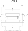
- FIGS. 2 and 3 illustrate an example of a roll segment included in the light rolling reduction zone 14.
- FIGS. 2 and 3 illustrate an example in which five pairs of cast steel support rolls 6 as rolling reduction rolls are arranged in one roll segment 15.
- FIG. 2 is a schematic diagram of the roll segment 15 as seen from the side of the continuous casting machine.
- FIG. 3 is a schematic diagram of the roll segment 15 as seen in a cross section orthogonal to the casting direction of cast steel.
- the roll segment 15 includes a pair of frames 16 and 16' that hold five pairs of cast steel support rolls 6 via roll chocks 21.
- a total of four support columns 17 (both sides on the upstream side and both sides on the downstream side) are arranged to pass through the frames 16 and 16'.
- Driving worm jacks 19 installed on the support columns 17 using motors 20 can adjust the distance between the frames 16 and 16', that is, the rolling reduction gradient in the roll segment 15.
- the upper frame 16' holds the cast steel support rolls 6 via roll chocks 21 connected to cylinder rods (not illustrated) of hydraulic cylinders 22 fixed to the frame 16'.
- the molten steel 9 poured into the mold 5 from the tundish 2 through the immersion nozzle 4 is cooled in the mold 5 to form a solidified shell 11.
- the molten steel 9 is then continuously withdrawn below the mold 5 while being supported by the cast steel support rolls 6 located below the mold 5, as the cast steel 10 having an unsolidified layer 12 inside.
- the cast steel 10 is cooled by the secondary coolant in the secondary cooling zone, as a result of which the thickness of the solidified shell 11 increases.
- the cast steel 10 is subjected to rolling reduction and is completely solidified to the inside at the solidification completion position 13.
- the cast steel 10 after the solidification completion is cut by the cast steel cutter 8 into the cast steel 10a.
- the cast steel withdrawn from the mold 5 is cast while being supported by the plurality of pairs of cast steel support rolls 6, each pair of cast steel support rolls 6 facing each other with the cast steel therebetween.
- the size of the cast steel produced is not limited.
- the thickness of the cast steel is preferably 200 mm or more.
- the thickness of the cast steel is preferably 600 mm or less.
- the width of the cast steel is preferably 1000 mm or more.
- the width of the cast steel is preferably 2500 mm or less. If the thickness and width of the cast steel are within these ranges, the rolling reduction gradient is better.
- the gap between the facing cast steel support rolls 6 is increased toward the downstream side in the casting direction, in some section.
- the rectangular cast steel having the unsolidified layer inside can be bulged on its wide faces.
- the cast steel can be bulged on its wide faces by 0.1 % to 10 % of the thickness of the cast steel in the mold. This can prevent the cast steel from being under excessive load during the subsequent light rolling reduction. If the bulging amount is 10 % or less, it is possible to prevent excessive strain from being applied to the solidification interface of the slab, so that internal cracking can be suppressed more appropriately.
- the range where bulging is performed is preferably set between the lower end of the mold 5 and the liquidus crater end position of the cast steel 10. This is because, on the upstream side of the liquidus crater end position of the cast steel 10 in the casting direction, the thickness central part of the cast steel is entirely the unsolidified layer 12 (liquid phase) and the solidified shell 11 of the cast steel 10 is high in temperature and low in deformation resistance and can be bulged easily. If the cast steel 10 is bulged when the amount of the unsolidified layer 12 inside the cast steel 10 is small, central segregation worsens.
- Rolling reduction is applied to the cast steel by a roll segment having a plurality of pairs of cast steel support rolls whose rolling reduction amounts are controlled by hydraulic cylinders, at least in the range from the position where the solid phase rate of the thickness central part of the cast steel is 0.2 to the position where the solid phase rate is the critical solid fraction of fluid flow in the casting direction of the cast steel.
- Rolling reduction is started at least from the position where the solid phase rate of the thickness central part of the cast steel is 0.2.
- Rolling reduction may be started before the solid phase rate of the thickness central part of the cast steel is 0.2.
- rolling reduction may be started from the position where the solid phase rate of the thickness central part of the cast steel is 0.
- the solid phase rate is 0 before the solidification start and 1.0 at the solidification completion.
- the solid phase rate of the central part is calculated from the estimated temperature of the central part by two-dimensional heat transfer solidification calculation.
- the critical solid fraction is typically 0.7 to 0.8, and can be derived by a known method.
- the part of the cast steel to which rolling reduction is applied is not limited, but it is preferable to apply rolling reduction over the entire width of the cast steel.
- the measured reaction force corresponds to the load difference between the ferrostatic pressure in the unsolidified part and the rolling reduction load in the solidified part in the width central part. Therefore, if rolling reduction is applied to the cast steel in a state where such a rolling reduction gradient is set that balances the rolling reduction load in the solidified part with the ferrostatic pressure, it may not be possible to determine whether the cast steel is solidified.
- the pressure difference between a plurality of hydraulic cylinders is measured, the final solidification position of the cast steel is estimated based on the pressure difference, and the rolling reduction amount of the cast steel is controlled to satisfy the following formulas (1) and (2) in the roll segment estimated to be the final solidification position and the roll segment immediately preceding the roll segment: 0.50 ⁇ V ⁇ Z ⁇ 3.00 0.5 R ⁇ Db ⁇ 2 R where V is the withdrawal speed of the cast steel (m/min), Z is the rolling reduction gradient (mm/m), Db is the bulging amount of the cast steel (mm), and R is the total rolling reduction amount of the cast steel (mm).
- V ⁇ Z means the rolling reduction speed of the cast steel (mm/min).
- V ⁇ Z being more than 0.50, the flow of concentrated molten steel can be appropriately suppressed and V segregation can be appropriately prevented.
- V ⁇ Z being less than 3.00, excessive pushing of concentrated molten steel due to excessive rolling reduction can be appropriately prevented and inverse V segregation can be appropriately prevented.
- V ⁇ Z is preferably 0.70 or more.
- V ⁇ Z is preferably 1.20 or less.
- Db is more than 0.5R, the effect of preventing the rolling reduction reaction force of the cast steel from being excessive is achieved.
- Db being less than 2R, the effect of preventing the rolling reduction reaction force of the cast steel from being excessive and also preventing internal cracking of the cast steel due to excessive bulging is achieved.
- Db is preferably 0.7R or more.
- Db is preferably 1.8R or less.
- the withdrawal speed V of the cast steel means the cast steel withdrawal speed calculated based on the rotation speed of the pinch rolls.
- the rolling reduction gradient Z means the narrowing amount of the roll gap per 1 m in the casting direction between the roll segment estimated to be the final solidification position and the roll segment immediately preceding the roll segment.
- the bulging amount Db of the cast steel (mm) means the difference between the roll gap at the lower end of the mold and the roll gap of the segment before light rolling reduction starts.
- the total rolling reduction amount R of the cast steel (mm) means the total rolling reduction in casting.
- the final solidification position of the cast steel is estimated by measuring the pressure difference between a plurality of hydraulic cylinders, so that the final solidification position can be identified easily and rolling reduction can be applied at an appropriate position.
- the pressure difference between the hydraulic cylinders is (the head pressure on the entry side of the roll segment) - (the head pressure on the exit side of the roll segment).
- the respective loads exerted on the support column 17a on the entry side of the roll segment and the support column 17b on the exit side of the roll segment can be calculated.
- the frame 16' is pressed by the hydraulic cylinder with the rod pressure set constant (for example, 20 MPa). Responsively, the head pressure is balanced to control the positions of the cast steel support rolls 6 constant. When the frame receives a reaction force from the cast steel, the head pressure is decreased to balance the sum of the reaction force from the cast steel and the head pressure with the rod pressure.
- the rod pressure the head pressure + the reaction force from the cast steel.
- the reaction force from the cast steel is greater, the head pressure is lower.
- the reaction force from the roll segment is greater than when cast steel having an unsolidified part is subjected to rolling reduction.
- the load is small on the segment entry side and large on the segment exit side.
- FIG. 4 is a graph illustrating the pressure difference between hydraulic cylinders against the casting length in each roll segment.
- segments 1, 2, and 3 are data for roll segments located at the most downstream, the middle, and the most upstream, respectively.
- the pressure difference between the hydraulic cylinder located on the segment entry side and the hydraulic cylinder located on the segment exit side is greater.
- the pressure difference between the hydraulic cylinders increases from the point when the bottom part of the cast steel enters the roll segment and then decreases from the point when the bottom part of the cast steel leaves the roll segment, but the pressure difference remains large in the case where the final solidification position is in the roll segment.
- the pressure difference decreases to less than 2 MPa after the bottom part passes through the segment.
- the pressure difference remains 2 MPa or more even after the bottom part passes through the segment.
- the segment 1 can therefore be estimated to be the final solidification position of the cast steel.
- the final solidification position is estimated by calculating the pressure difference between hydraulic cylinders for each roll segment. Hence, it is easy to estimate the final solidification position from a wide range even if the final solidification position varies greatly due to changes in the thickness of cast steel, the withdrawal speed, or the steel type.
- Casting conditions other than those described above may be in accordance with conventional methods.
- This steel continuous casting method can reduce central segregation of cast steel.
- the carbon concentration is analyzed at equal intervals in the thickness direction of the cast steel to determine C max /C 0 as the central segregation degree, where C max is the maximum carbon concentration in the thickness direction and C 0 is the carbon concentration analyzed for molten steel collected from the tundish during casting.
- a central segregation degree closer to 1.000 indicates better cast steel with less central segregation.
- cast steel whose C max /C 0 is less than 1.100 can be produced. No lower limit is placed on the central segregation degree, but the central segregation degree is typically 1.000 or more.
- This steel continuous casting method can also suppress porosity and internal cracking of cast steel.
- the slab continuous casting machine used in the test is the same as the slab continuous casting machine 1 illustrated in FIG. 1 .
- Low carbon aluminum killed steel was cast using this slab continuous casting machine.
- the thickness of cast steel at the lower end of the mold was 250 mm, 400 mm, or 600 mm.
- the width of cast steel was 2200 mm in each test.
- Table 1 shows the casting conditions and the results of investigating the central segregation degree in the cast steel, whether porosity occurred, and whether internal cracking occurred.
- Table 1 also shows the casting conditions and investigation results of the tests conducted as comparative examples.
- the rolling reduction start position, the rolling reduction end position, the position where the solid phase rate of the thickness central part of the cast steel is 0.2, and the final solidification position are expressed in terms of the distance from the meniscus in the mold.
- the central segregation degree of the cast steel used in the evaluation test was measured by the following method: In a cross section orthogonal to the withdrawal direction of the cast steel, the carbon concentration was analyzed at equal intervals in the thickness direction of the cast steel to determine C max /C 0 as the central segregation degree, where C max is the maximum carbon concentration in the thickness direction and C 0 is the carbon concentration analyzed for molten steel collected from the tundish during casting. A central segregation degree closer to 1.000 indicates better cast steel with less central segregation.
- cast steel with a central segregation degree of 1.100 or more was determined to have a poor central segregation degree.
- the cast steel withdrawal speed for each cast steel thickness was set so that at least the cast steel in the section from the position where the solid phase rate of the thickness central part of the cast steel is 0.2 to the position where the solid phase rate is the critical solid fraction of fluid flow would be located in the light rolling reduction zone.
- the rolling reduction gradient and the bulging amount were set to satisfy the foregoing formulas (1) and (2) in the roll segment estimated to be the final solidification position and the roll segment immediately preceding the roll segment.
- the roll segment in which the pressure difference between the hydraulic cylinder located on the segment entry side and the hydraulic cylinder located on the segment exit side was 2 MPa or more was identified.
Landscapes
- Engineering & Computer Science (AREA)
- Mechanical Engineering (AREA)
- Continuous Casting (AREA)
Abstract
Description
- The present disclosure relates to a steel continuous casting method.
- During the final solidification process in continuous casting of steel, solidification shrinkage causes suction flow of unsolidified molten steel (referred to as "unsolidified layer") in the cast steel withdrawal direction. In the unsolidified layer, solute elements such as carbon (C), phosphorus (P), sulfur (S), and manganese (Mn) are concentrated. When such concentrated molten steel flows to the central part of the cast steel and solidifies, central segregation occurs.
- Central segregation degrades the quality of steel products, especially steel plates. For example, in line pipe materials for transporting oil or natural gas, hydrogen-induced cracking occurs starting from central segregation due to the action of sour gas. Similar problems occur in marine structures, storage tanks, oil tanks, etc. In recent years, steel materials are often required to be used in harsh environments such as lower temperature environments or more corrosive environments. This makes it increasingly important to reduce central segregation in cast steel.
- Many measures have thus been proposed to reduce or neutralize central segregation in cast steel from the continuous casting process to the rolling process. Among these measures, a solidification end stage light rolling reduction method of, in a continuous casting machine, applying rolling reduction to continuous-cast steel having an unsolidified layer inside is known to be particularly effective in improving central segregation. The solidification end stage light rolling reduction method is a method in which rolling reduction rolls are placed near the solidification completion position of cast steel and, with the rolling reduction rolls, cast steel during continuous casting is gradually roll-reduced at a rolling reduction speed equivalent to the sum of the solidification shrinkage amount and the thermal shrinkage amount. In this way, the occurrence of voids and the flow of concentrated molten steel in the central part of the cast steel can be suppressed to prevent central segregation in the cast steel.
- In order to effectively prevent central segregation in cast steel using the solidification end stage light rolling reduction method, it is essential to appropriately set the conditions for light rolling reduction, for example, the start and end of the period during which light rolling reduction is applied in the final solidification period of the cast steel, and the rolling reduction amount of the light rolling reduction. In view of this, methods of setting the conditions and methods of estimating the final solidification position have been proposed.
- For example,
JP 2018-199137 A -
JP 2013-22609 A -
- PTL 1:
JP 2018-199137 A - PTL 2:
JP 2013-22609 A - In the crater end detection device described in
PTL 1, a load measurement device is installed in each of the bearing boxes located at both ends of the backup rolls. In a high temperature environment during casting, the load measurement device installed in the bearing box is under heavy load and is highly likely to fail. When the load measurement device fails, the segment needs to be replaced, which is costly. - The steel continuous casting method described in
PTL 2 has the possibility of errors in the calculation of the central solid phase rate. - It could therefore be helpful to provide a steel continuous casting method that can identify the final solidification position accurately and inexpensively.
- Upon careful examination, we conceived utilizing the pressure difference between hydraulic cylinders to predict when to start light rolling reduction and when to end light rolling reduction in slab continuous casting using the solidification end stage light rolling reduction method. By measuring the pressure difference between hydraulic cylinders, the final solidification position can be identified accurately and inexpensively.
- The present disclosure is based on these discoveries. We thus provide the following.
- [1] A steel continuous casting method of casting cast steel withdrawn from a mold while supporting the cast steel by a plurality of pairs of cast steel support rolls, cast steel support rolls of each of the plurality of pairs facing each other with the cast steel therebetween, the steel continuous casting method comprising: increasing a gap between the facing cast steel support rolls toward a downstream side in a casting direction of the cast steel, in a section; applying rolling reduction to the cast steel by a roll segment having a plurality of pairs of cast steel support rolls whose rolling reduction amounts are controlled by hydraulic cylinders, at least in a range from a position where a solid phase rate of a thickness central part of the cast steel is 0.2 to a position where the solid phase rate is a critical solid fraction of fluid flow in the casting direction; measuring a pressure difference between a plurality of hydraulic cylinders and estimating a final solidification position of the cast steel based on the pressure difference; and controlling a rolling reduction amount of the cast steel so as to satisfy the following formulas (1) and (2) in a roll segment estimated to be the final solidification position and a roll segment immediately preceding the roll segment:


- It is thus possible to provide a steel continuous casting method that can identify the final solidification position accurately and inexpensively.
- In the accompanying drawings:
-
FIG. 1 is a diagram illustrating an example of the schematic structure of a slab continuous casting machine; -
FIG. 2 is a schematic diagram illustrating an example of a roll segment included in a light rolling reduction zone in the slab continuous casting machine, as seen from the side of the continuous casting machine; -
FIG. 3 is a schematic diagram illustrating the roll segment illustrated inFIG. 2 in a cross section orthogonal to the casting direction of cast steel; and -
FIG. 4 is a graph illustrating the pressure difference between hydraulic cylinders against the casting length in each roll segment. - Embodiments of the present disclosure will be described below. The present disclosure is not limited to these embodiments.
- A steel production method according to an embodiment of the present disclosure is a steel continuous casting method of casting cast steel withdrawn from a mold while supporting the cast steel by a plurality of pairs of cast steel support rolls, cast steel support rolls of each of the plurality of pairs facing each other with the cast steel therebetween, the steel continuous casting method comprising: increasing a gap between the facing cast steel support rolls toward a downstream side in a casting direction of the cast steel, in a section; applying rolling reduction to the cast steel by a roll segment having a plurality of pairs of cast steel support rolls whose rolling reduction amounts are controlled by hydraulic cylinders, at least in a range from a position where a solid phase rate of a thickness central part of the cast steel is 0.2 to a position where the solid phase rate is a critical solid fraction of fluid flow in the casting direction; measuring a pressure difference between a plurality of hydraulic cylinders and estimating a final solidification position of the cast steel based on the pressure difference; and controlling a rolling reduction amount of the cast steel so as to satisfy the following formulas (1) and (2) in a roll segment estimated to be the final solidification position and a roll segment immediately preceding the roll segment:


-
FIG. 1 is a diagram illustrating the schematic structure of a slab continuous casting machine used when carrying out the steel continuous casting method according to the embodiment. As illustrated inFIG. 1 , in one example, amold 5 in whichmolten steel 9 is poured and solidified to form the outer shell shape of cast steel (slab) 10 is installed in a slabcontinuous casting machine 1. A tundish 2 for relaying themolten steel 9 supplied from a ladle (not illustrated) to themold 5 is installed at a certain position above themold 5. A slidingnozzle 3 for adjusting the flow rate of themolten steel 9 is installed at the bottom of the tundish 2. Animmersion nozzle 4 is installed on the underside of thesliding nozzle 3. A plurality of pairs of caststeel support rolls 6 composed of support rolls, guide rolls, and pinch rolls are arranged below themold 5. A secondary cooling zone is formed by arranging spray nozzles such as water spray nozzles or air mist spray nozzles (not illustrated) in the gaps between the caststeel support rolls 6 adjacent in the casting direction. A coolant (also referred to as "secondary coolant") sprayed from the spray nozzles in the secondary cooling zone cools thecast steel 10 that is being withdrawn. A plurality ofconveyance rolls 7 for conveying thecast steel 10 are installed on the downstream side of the caststeel support rolls 6 at the end in the casting direction. Acast steel cutter 8 for cuttingcast steel 10a of a certain length from thecast steel 10 is located above theconveyance rolls 7. - A light
rolling reduction zone 14 composed of a plurality of pairs of cast steel support rolls is installed on both the upstream and downstream sides of thesolidification completion position 13 of thecast steel 10 in the casting direction. In the lightrolling reduction zone 14, the distance (referred to as "roll gap") between the cast steel support rolls facing each other with thecast steel 10 therebetween gradually narrows toward the downstream side in the casting direction. In other words, a rolling reduction gradient (i.e. the state of the roll gap set to gradually narrow toward the downstream side in the casting direction) is set in the lightrolling reduction zone 14. Thecast steel 10 can be subjected to light rolling reduction in the entire region or a selected region of the lightrolling reduction zone 14. Spray nozzles for cooling thecast steel 10 are arranged between the cast steel support rolls in the lightrolling reduction zone 14. The caststeel support rolls 6 arranged in the lightrolling reduction zone 14 are also called rolling reduction rolls. - In the slab
continuous casting machine 1 illustrated inFIG. 1 , three roll segments each of which is composed of three pairs of caststeel support rolls 6 are connected in the casting direction. In the present disclosure, however, the lightrolling reduction zone 14 need not necessarily be composed of three roll segments, and the number of roll segments constituting the lightrolling reduction zone 14 may be one, two, or four or more. Moreover, although each roll segment is composed of three pairs of cast steel support rolls 6 in this embodiment, the number of cast steel support rolls 6 constituting one roll segment is not limited. -
FIGS. 2 and3 illustrate an example of a roll segment included in the light rollingreduction zone 14.FIGS. 2 and3 illustrate an example in which five pairs of cast steel support rolls 6 as rolling reduction rolls are arranged in oneroll segment 15.FIG. 2 is a schematic diagram of theroll segment 15 as seen from the side of the continuous casting machine.FIG. 3 is a schematic diagram of theroll segment 15 as seen in a cross section orthogonal to the casting direction of cast steel. - As illustrated in
FIGS. 2 and3 , in one example, theroll segment 15 includes a pair offrames 16 and 16' that hold five pairs of cast steel support rolls 6 via roll chocks 21. A total of four support columns 17 (both sides on the upstream side and both sides on the downstream side) are arranged to pass through theframes 16 and 16'. Driving worm jacks 19 installed on thesupport columns 17 usingmotors 20 can adjust the distance between theframes 16 and 16', that is, the rolling reduction gradient in theroll segment 15. The upper frame 16' holds the cast steel support rolls 6 via roll chocks 21 connected to cylinder rods (not illustrated) of hydraulic cylinders 22 fixed to the frame 16'. - In the slab
continuous casting machine 1, themolten steel 9 poured into themold 5 from thetundish 2 through theimmersion nozzle 4 is cooled in themold 5 to form a solidifiedshell 11. Themolten steel 9 is then continuously withdrawn below themold 5 while being supported by the cast steel support rolls 6 located below themold 5, as thecast steel 10 having anunsolidified layer 12 inside. While passing through the cast steel support rolls 6, thecast steel 10 is cooled by the secondary coolant in the secondary cooling zone, as a result of which the thickness of the solidifiedshell 11 increases. Moreover, in the light rollingreduction zone 14, thecast steel 10 is subjected to rolling reduction and is completely solidified to the inside at thesolidification completion position 13. Thecast steel 10 after the solidification completion is cut by thecast steel cutter 8 into thecast steel 10a. - In the steel casting method according to this embodiment, the cast steel withdrawn from the
mold 5 is cast while being supported by the plurality of pairs of cast steel support rolls 6, each pair of cast steel support rolls 6 facing each other with the cast steel therebetween. The size of the cast steel produced is not limited. The thickness of the cast steel is preferably 200 mm or more. The thickness of the cast steel is preferably 600 mm or less. The width of the cast steel is preferably 1000 mm or more. The width of the cast steel is preferably 2500 mm or less. If the thickness and width of the cast steel are within these ranges, the rolling reduction gradient is better. - The gap between the facing cast steel support rolls 6 is increased toward the downstream side in the casting direction, in some section. By increasing the gap between the cast steel support rolls 6 toward the downstream side in the casting direction, the rectangular cast steel having the unsolidified layer inside can be bulged on its wide faces. In one example, the cast steel can be bulged on its wide faces by 0.1 % to 10 % of the thickness of the cast steel in the mold. This can prevent the cast steel from being under excessive load during the subsequent light rolling reduction. If the bulging amount is 10 % or less, it is possible to prevent excessive strain from being applied to the solidification interface of the slab, so that internal cracking can be suppressed more appropriately. The range where bulging is performed is preferably set between the lower end of the
mold 5 and the liquidus crater end position of thecast steel 10. This is because, on the upstream side of the liquidus crater end position of thecast steel 10 in the casting direction, the thickness central part of the cast steel is entirely the unsolidified layer 12 (liquid phase) and the solidifiedshell 11 of thecast steel 10 is high in temperature and low in deformation resistance and can be bulged easily. If thecast steel 10 is bulged when the amount of theunsolidified layer 12 inside thecast steel 10 is small, central segregation worsens. In contrast, if thecast steel 10 is bulged on the upstream side of the liquidus crater end position of thecast steel 10 in the casting direction, molten steel of the initial concentration in which solute elements are not concentrated is abundantly present inside the cast steel at this stage and this molten steel flows easily. Flow of such molten steel does not cause central segregation. Thus, bulging on the upstream side of the liquidus crater end position in the casting direction does not cause central segregation. - Rolling reduction is applied to the cast steel by a roll segment having a plurality of pairs of cast steel support rolls whose rolling reduction amounts are controlled by hydraulic cylinders, at least in the range from the position where the solid phase rate of the thickness central part of the cast steel is 0.2 to the position where the solid phase rate is the critical solid fraction of fluid flow in the casting direction of the cast steel. Rolling reduction is started at least from the position where the solid phase rate of the thickness central part of the cast steel is 0.2. Rolling reduction may be started before the solid phase rate of the thickness central part of the cast steel is 0.2. For example, rolling reduction may be started from the position where the solid phase rate of the thickness central part of the cast steel is 0. Herein, the solid phase rate is 0 before the solidification start and 1.0 at the solidification completion. The solid phase rate of the central part is calculated from the estimated temperature of the central part by two-dimensional heat transfer solidification calculation. The critical solid fraction is typically 0.7 to 0.8, and can be derived by a known method.
- The part of the cast steel to which rolling reduction is applied is not limited, but it is preferable to apply rolling reduction over the entire width of the cast steel. For example, in the case of measuring the reaction force in the width central part as in the method using a load measurement device described in
PTL 1, the measured reaction force corresponds to the load difference between the ferrostatic pressure in the unsolidified part and the rolling reduction load in the solidified part in the width central part. Therefore, if rolling reduction is applied to the cast steel in a state where such a rolling reduction gradient is set that balances the rolling reduction load in the solidified part with the ferrostatic pressure, it may not be possible to determine whether the cast steel is solidified. If rolling reduction is applied over the entire width of the cast steel, on the other hand, the pressure difference corresponding to the reaction force received over the entire width of the cast steel is measured, so that the final solidification position can be estimated more accurately with there being no need to consider the balance between the ferrostatic pressure and the rolling reduction load in the solidified part. - In the steel casting method according to this embodiment, the pressure difference between a plurality of hydraulic cylinders is measured, the final solidification position of the cast steel is estimated based on the pressure difference, and the rolling reduction amount of the cast steel is controlled to satisfy the following formulas (1) and (2) in the roll segment estimated to be the final solidification position and the roll segment immediately preceding the roll segment:


- By performing rolling reduction so as to satisfy the formulas (1) and (2), it is possible to effectively prevent central segregation and porosity without internal cracking.
- In the formula (1), V × Z means the rolling reduction speed of the cast steel (mm/min). As a result of V × Z being more than 0.50, the flow of concentrated molten steel can be appropriately suppressed and V segregation can be appropriately prevented. As a result of V × Z being less than 3.00, excessive pushing of concentrated molten steel due to excessive rolling reduction can be appropriately prevented and inverse V segregation can be appropriately prevented. V × Z is preferably 0.70 or more. V × Z is preferably 1.20 or less.
- In the formula (2), as a result of Db being more than 0.5R, the effect of preventing the rolling reduction reaction force of the cast steel from being excessive is achieved. As a result of Db being less than 2R, the effect of preventing the rolling reduction reaction force of the cast steel from being excessive and also preventing internal cracking of the cast steel due to excessive bulging is achieved. Db is preferably 0.7R or more. Db is preferably 1.8R or less.
- Here, pinch rolls are rotated to withdraw the cast steel. The withdrawal speed V of the cast steel (m/min) means the cast steel withdrawal speed calculated based on the rotation speed of the pinch rolls.
- The rolling reduction gradient Z (mm/m) means the narrowing amount of the roll gap per 1 m in the casting direction between the roll segment estimated to be the final solidification position and the roll segment immediately preceding the roll segment.
- The bulging amount Db of the cast steel (mm) means the difference between the roll gap at the lower end of the mold and the roll gap of the segment before light rolling reduction starts.
- The total rolling reduction amount R of the cast steel (mm) means the total rolling reduction in casting.
- As mentioned above, in the case of measurement using a load measurement device, in a high temperature environment during casting, the load measurement device is under heavy load and is highly likely to fail. When the load measurement device fails, the segment needs to be replaced, which is costly. According to the present disclosure, the final solidification position of the cast steel is estimated by measuring the pressure difference between a plurality of hydraulic cylinders, so that the final solidification position can be identified easily and rolling reduction can be applied at an appropriate position. Here, the pressure difference between the hydraulic cylinders is (the head pressure on the entry side of the roll segment) - (the head pressure on the exit side of the roll segment). By measuring the respective pressures of the
hydraulic cylinder 22a on the entry side of the roll segment and thehydraulic cylinder 22b on the exit side of the roll segment, the respective loads exerted on thesupport column 17a on the entry side of the roll segment and thesupport column 17b on the exit side of the roll segment can be calculated. There are two types of pressure of a hydraulic cylinder: head pressure and rod pressure. The frame 16' is pressed by the hydraulic cylinder with the rod pressure set constant (for example, 20 MPa). Responsively, the head pressure is balanced to control the positions of the cast steel support rolls 6 constant. When the frame receives a reaction force from the cast steel, the head pressure is decreased to balance the sum of the reaction force from the cast steel and the head pressure with the rod pressure. That is, the rod pressure = the head pressure + the reaction force from the cast steel. Thus, when the reaction force from the cast steel is greater, the head pressure is lower. When solidified cast steel after the final solidification position in a roll segment is subjected to rolling reduction, the reaction force from the roll segment is greater than when cast steel having an unsolidified part is subjected to rolling reduction. Meanwhile, in a roll segment corresponding to the final solidification position, the load is small on the segment entry side and large on the segment exit side. Hence, by identifying a roll segment where the pressure difference between the hydraulic cylinder located on the segment entry side and the hydraulic cylinder located on the segment exit side is greater than or equal to a predetermined value, the final solidification position of the cast steel can be estimated. The pressure difference between the hydraulic cylinder located on the segment entry side and the hydraulic cylinder located on the segment exit side is not limited, but is preferably 2 MPa or more. -
FIG. 4 is a graph illustrating the pressure difference between hydraulic cylinders against the casting length in each roll segment. InFIG. 4 ,segments FIG. 4 , in each of the mostupstream segment 3 and themiddle segment 2, the pressure difference decreases to less than 2 MPa after the bottom part passes through the segment. In the mostdownstream segment 1, on the other hand, the pressure difference remains 2 MPa or more even after the bottom part passes through the segment. Thesegment 1 can therefore be estimated to be the final solidification position of the cast steel. - In the case where a load measurement device is used to estimate the final solidification position, it is necessary to install a load measurement device for each rolling reduction roll. This requires a large number of sensors in order to estimate the final solidification position from a wide range in the casting direction. According to the present disclosure, the final solidification position is estimated by calculating the pressure difference between hydraulic cylinders for each roll segment. Hence, it is easy to estimate the final solidification position from a wide range even if the final solidification position varies greatly due to changes in the thickness of cast steel, the withdrawal speed, or the steel type.
- Casting conditions other than those described above may be in accordance with conventional methods.
- This steel continuous casting method can reduce central segregation of cast steel. In a cross section orthogonal to the withdrawal direction of cast steel, the carbon concentration is analyzed at equal intervals in the thickness direction of the cast steel to determine Cmax/C0 as the central segregation degree, where Cmax is the maximum carbon concentration in the thickness direction and C0 is the carbon concentration analyzed for molten steel collected from the tundish during casting. A central segregation degree closer to 1.000 indicates better cast steel with less central segregation. With this steel continuous casting method, cast steel whose Cmax/C0 is less than 1.100 can be produced. No lower limit is placed on the central segregation degree, but the central segregation degree is typically 1.000 or more. This steel continuous casting method can also suppress porosity and internal cracking of cast steel.
- The presently disclosed techniques will be described in more detail below by way of examples.
- The slab continuous casting machine used in the test is the same as the slab
continuous casting machine 1 illustrated inFIG. 1 . Low carbon aluminum killed steel was cast using this slab continuous casting machine. The thickness of cast steel at the lower end of the mold was 250 mm, 400 mm, or 600 mm. The width of cast steel was 2200 mm in each test. Table 1 shows the casting conditions and the results of investigating the central segregation degree in the cast steel, whether porosity occurred, and whether internal cracking occurred. Table 1 also shows the casting conditions and investigation results of the tests conducted as comparative examples. In Table 1, the rolling reduction start position, the rolling reduction end position, the position where the solid phase rate of the thickness central part of the cast steel is 0.2, and the final solidification position are expressed in terms of the distance from the meniscus in the mold. In Table 1, in each test in which rolling reduction range control is indicated as "Performed", since, in the initially set light rolling reduction range, the rolling reduction start position and rolling reduction end position were outside the appropriate range, the rolling reduction range was adjusted based on the final solidification position measured during casting. -
Table 1 No. Cast steel thickness (mm) Position of solid phase rate of 0.2 (m) Final solidification position (m) Rolling reduction start position (m) Rolling reduction end position (m) Rolling reduction range control Withdrawal speed V (m/min) Rolling reduction gradient Z (mm/m) V×Z Total rolling reduction amount R (mm) 0.5R 2R Bulging amount Db (mm) Central segregation degree (Cmax/C0) Porosity Internal cracking Bulging amount 0.1-10% of cast steel thickness (mm) 1 Example 250 24.0 26.2 20 28 Not performed 1.20 1.2 1.44 9.6 4.8 19.2 5.0 1.058 Not occurred Not occurred 0.25-25 2 22.5 25.8 20 28 Not performed 1.10 1.1 1.21 8.8 4.4 17.6 10.0 1.049 Not occurred Not occurred 0.25-25 3 4 18.0 22.1 16 24 Performed 0.80 1.5 1.20 12.0 6.0 24.0 8.0 1.060 Not occurred Not occurred 0.25-25 24.0 26.0 20 28 Not performed 1.00 0.6 0.55 4.4 2.2 8.8 4.0 1.096 Not occurred Not occurred 0.25-25 5 25.0 27.7 24 30 Not performed 1.00 2.9 2.90 17.4 8.7 34.8 10.0 1.064 Not occurred Not occurred 0.25-25 6 Comparative Example 16.0 19.8 18 26 Not performed 0.70 1.1 0.77 8.8 4.4 17.6 5.0 1.129 Occurred Not occurred 0.25-25 7 23.8 26.1 20 28 Not performed 1.10 0.4 0.44 3.2 1.6 6.4 4.0 1.105 Not occurred Not occurred 0.25-25 8 - 24.0 26.5 20 28 Not performed 1.40 2.8 3.92 22.4 11.2 44.8 10.0 1.108 Not occurred Occurred 0.25-25 9 Example 400 30.0 33.4 28 34 Not performed 0.60 2.0 1.20 12.0 6.0 24.0 8.0 1.062 Not occurred Not occurred 0.4-40 10 28.2 31.4 26 32 Not performed 0.70 2.4 1.68 14.4 7.2 28.8 8.0 1.055 Not occurred Not occurred 0.4-40 11 31.0 34.2 30 36 Performed 0.60 2.2 1.32 13.2 6.6 26.4 9.0 1.058 Not occurred Not occurred 0.4-40 12 30.0 33.8 28 34 Not performed 0.52 1.0 0.52 6.0 3.0 12.0 8.0 1.089 Not occurred Not occurred 0.4-40 13 28.5 30.0 28 32 Not performed 0.60 4.8 2.88 19.2 9.6 38.4 15.0 1.072 Not occurred Not occurred 0.4-40 14 Comparative Example 30.2 33.6 26 32 Not performed 0.65 2.5 1.63 15.0 7.5 30.0 10.0 1.130 Occurred Not occurred 0.4-40 15 - 26.2 28.9 24 30 Not performed 0.70 0.6 0.42 3.6 1.8 7.2 5.0 1.108 Occurred Not occurred 0.4-40 16 27.2 30.0 24 30 Not performed 0.60 2.0 1.20 12.0 6.0 24.0 5.0 1.120 Occurred Not occurred 0.4-40 17 Example 600 320 36.5 30 38 Not performed 0.42 3.0 1.26 24.0 12.0 48.0 18.0 1.048 Not occurred Not occurred 0.6-60 18 34.0 37.2 32 40 Not performed 0.55 3.4 1.87 27.2 13.6 54.4 20.0 1.059 Not occurred Not occurred 0.6-60 19 33.4 36.4 32 40 Performed 0.60 2.5 1.50 20.0 10.0 40.0 15.0 1.055 Not occurred Not occurred 0.6-60 20 34.2 36.8 32 38 Not performed 0.50 1.1 0.55 6.6 3.3 13.2 9.0 1.088 Not occurred Not occurred 0.6-60 21 34.5 37.2 34 38 Not performed 0.58 5.0 2.90 20.0 10.0 40.0 15.0 1.069 Not occurred Not occurred 0.6-60 22 Comparative Example 29.0 32.1 30 38 Not performed 0.45 2.4 1.08 19.2 9.6 38.4 5.0 1.135 Occurred Not occurred 0.6-60 23 - 322 36.8 30 38 Not performed 0.60 5.8 3.48 46.4 23.2 92.8 25.0 1.102 Not occurred Occurred 0.6-60 24 34.5 37.7 32 40 Not performed 0.65 1.5 0.98 12.0 6.0 24.0 30.0 1.243 Occurred Not occurred 0.6-60 - The central segregation degree of the cast steel used in the evaluation test was measured by the following method: In a cross section orthogonal to the withdrawal direction of the cast steel, the carbon concentration was analyzed at equal intervals in the thickness direction of the cast steel to determine Cmax/C0 as the central segregation degree, where Cmax is the maximum carbon concentration in the thickness direction and C0 is the carbon concentration analyzed for molten steel collected from the tundish during casting. A central segregation degree closer to 1.000 indicates better cast steel with less central segregation. Here, cast steel with a central segregation degree of 1.100 or more was determined to have a poor central segregation degree.
- Whether porosity and internal cracking occurred in the cast steel was determined through microscopic observation of the thickness central part of the cast steel in a cross section orthogonal to the withdrawal direction of the cast steel.
- The cast steel withdrawal speed for each cast steel thickness was set so that at least the cast steel in the section from the position where the solid phase rate of the thickness central part of the cast steel is 0.2 to the position where the solid phase rate is the critical solid fraction of fluid flow would be located in the light rolling reduction zone. In addition, in Test Nos. 1 to 5, 9 to 13, and 17 to 21, the rolling reduction gradient and the bulging amount were set to satisfy the foregoing formulas (1) and (2) in the roll segment estimated to be the final solidification position and the roll segment immediately preceding the roll segment. As the final solidification position, the roll segment in which the pressure difference between the hydraulic cylinder located on the segment entry side and the hydraulic cylinder located on the segment exit side was 2 MPa or more was identified. In Test Nos. 6, 14, and 22 of Comparative Examples, either the rolling reduction start position or the rolling reduction end position was outside the appropriate range. In Test Nos. 7, 8, 15, and 23, V × Z was outside the range of the formula (1). In Test Nos. 16, 22, and 24, the total rolling reduction amount and the bulging amount were outside the range of the formula (2).
- As is clear from the central segregation degree shown in Table 1, in Test Nos. 1 to 5, 9 to 13, and 17 to 21 of Examples, the central segregation degree was less than 1.100, which was good. Moreover, neither porosity nor internal cracking was observed in the cast steel.
- In Test Nos. 6, 14, and 22 of Comparative Examples, either the rolling reduction start position or the rolling reduction end position was outside the appropriate range, so that the central segregation degree was 1.100 or more and porosity was observed inside the cast steel. In Test Nos. 7 and 15 of Comparative Examples, the rolling reduction gradient was insufficient and the central segregation degree was 1.100 or more. Further, in Test No. 15, porosity was observed inside the cast steel. In Test Nos. 8 and 23, the rolling reduction gradient was excessively large, so that the central segregation degree was 1.100 or more and internal cracking occurred in the cast steel. In Test Nos. 16, 22, and 24, the total rolling reduction amount and the bulging amount were outside the range of the formula (2), so that the central segregation degree was 1.100 or more and porosity was observed inside the cast steel.
-
- 1
- slab continuous casting machine
- 2
- tundish
- 3
- sliding nozzle
- 4
- immersion nozzle
- 5
- mold
- 6
- cast steel support roll
- 7
- conveyance roll
- 8
- cast steel cutter
- 9
- molten steel
- 10
- cast steel
- 11
- solidified shell
- 12
- unsolidified layer
- 13
- solidification completion position
- 14
- light rolling reduction zone
- 15
- roll segment
- 16
- frame
- 17
- support column
- 19
- worm jack
- 20
- motor
- 21
- roll chock
- 22
- hydraulic cylinder
Claims (1)
- A steel continuous casting method of casting cast steel withdrawn from a mold while supporting the cast steel by a plurality of pairs of cast steel support rolls, cast steel support rolls of each of the plurality of pairs facing each other with the cast steel therebetween, the steel continuous casting method comprising:increasing a gap between the facing cast steel support rolls toward a downstream side in a casting direction of the cast steel, in a section;applying rolling reduction to the cast steel by a roll segment having a plurality of pairs of cast steel support rolls whose rolling reduction amounts are controlled by hydraulic cylinders, at least in a range from a position where a solid phase rate of a thickness central part of the cast steel is 0.2 to a position where the solid phase rate is a critical solid fraction of fluid flow in the casting direction;measuring a pressure difference between a plurality of hydraulic cylinders and estimating a final solidification position of the cast steel based on the pressure difference; andcontrolling a rolling reduction amount of the cast steel so as to satisfy the following formulas (1) and (2) in a roll segment estimated to be the final solidification position and a roll segment immediately preceding the roll segment:

 where V is a withdrawal speed of the cast steel in m/min, Z is a rolling reduction gradient in mm/m, Db is a bulging amount of the cast steel in mm, and R is a total rolling reduction amount of the cast steel in mm.
Applications Claiming Priority (2)
| Application Number | Priority Date | Filing Date | Title |
|---|---|---|---|
| JP2022104990 | 2022-06-29 | ||
| PCT/JP2023/019191 WO2024004447A1 (en) | 2022-06-29 | 2023-05-23 | Steel continuous casting method |
Publications (2)
| Publication Number | Publication Date |
|---|---|
| EP4501492A1 true EP4501492A1 (en) | 2025-02-05 |
| EP4501492A4 EP4501492A4 (en) | 2026-03-25 |
Family
ID=88509957
Family Applications (1)
| Application Number | Title | Priority Date | Filing Date |
|---|---|---|---|
| EP23830899.3A Pending EP4501492A4 (en) | 2022-06-29 | 2023-05-23 | STEEL CONTINUOUS CASTING PROCESS |
Country Status (5)
| Country | Link |
|---|---|
| US (1) | US20250319513A1 (en) |
| EP (1) | EP4501492A4 (en) |
| JP (1) | JP7371821B1 (en) |
| KR (1) | KR102954566B1 (en) |
| CN (1) | CN119255874A (en) |
Family Cites Families (5)
| Publication number | Priority date | Publication date | Assignee | Title |
|---|---|---|---|---|
| JPS606254A (en) * | 1983-06-25 | 1985-01-12 | Nippon Kokan Kk <Nkk> | Continuous casting method |
| JP3582378B2 (en) * | 1998-03-26 | 2004-10-27 | 住友金属工業株式会社 | Level control method for continuous casting and level control device for continuous casting |
| JP5686062B2 (en) * | 2011-07-20 | 2015-03-18 | 新日鐵住金株式会社 | Steel continuous casting method |
| JP6624396B2 (en) * | 2017-03-31 | 2019-12-25 | Jfeスチール株式会社 | Steel sheet manufacturing method |
| JP6961295B2 (en) | 2017-05-25 | 2021-11-05 | 日本製鉄株式会社 | Crater end position detection device for continuously cast slabs, roll segments incorporating it, and crater end position detection method for continuously cast slabs using them. |
-
2023
- 2023-05-23 JP JP2023547151A patent/JP7371821B1/en active Active
- 2023-05-23 KR KR1020247034208A patent/KR102954566B1/en active Active
- 2023-05-23 EP EP23830899.3A patent/EP4501492A4/en active Pending
- 2023-05-23 CN CN202380034295.1A patent/CN119255874A/en active Pending
- 2023-05-23 US US18/865,001 patent/US20250319513A1/en active Pending
Also Published As
| Publication number | Publication date |
|---|---|
| KR20240162121A (en) | 2024-11-14 |
| US20250319513A1 (en) | 2025-10-16 |
| JPWO2024004447A1 (en) | 2024-01-04 |
| EP4501492A4 (en) | 2026-03-25 |
| KR102954566B1 (en) | 2026-04-17 |
| CN119255874A (en) | 2025-01-03 |
| JP7371821B1 (en) | 2023-10-31 |
Similar Documents
| Publication | Publication Date | Title |
|---|---|---|
| JP5686062B2 (en) | Steel continuous casting method | |
| US10543527B2 (en) | Continuous steel casting method | |
| JP5962625B2 (en) | Steel continuous casting method | |
| EP2881196B1 (en) | Method for continuously casting steel | |
| EP3012044B1 (en) | Continuous casting method for casting for extra thick steel sheet | |
| JP5092642B2 (en) | Steel continuous casting method and continuous casting machine | |
| JP2012011459A (en) | Soft reduction method of cast slab in continuous casting | |
| JP5779978B2 (en) | Light reduction method of slab in continuous casting | |
| EP3246113B1 (en) | Continuously cast slab and manufacturing method and manufacturing device therefor | |
| JP6075336B2 (en) | Steel continuous casting method | |
| EP3760339B1 (en) | Continuous steel casting method using soft reduction with small rolling load | |
| US20250319513A1 (en) | Steel continuous casting method | |
| JP3511973B2 (en) | Continuous casting method | |
| EP3251774B1 (en) | Continuous casting method for steel | |
| WO2024004447A1 (en) | Steel continuous casting method | |
| JP5910577B2 (en) | Steel continuous casting method | |
| EP4711060A1 (en) | Slab manufacturing method | |
| JP7609290B2 (en) | Steel continuous casting method and continuous casting machine | |
| JP2000288705A (en) | Continuous casting method | |
| JP3395674B2 (en) | Continuous casting method | |
| JP2003025053A (en) | Method for continuously casting steel slab | |
| JPH11285797A (en) | Continuous casting method | |
| BR112020017364B1 (en) | CONTINUOUS STEEL CASTING METHOD |
Legal Events
| Date | Code | Title | Description |
|---|---|---|---|
| STAA | Information on the status of an ep patent application or granted ep patent |
Free format text: STATUS: THE INTERNATIONAL PUBLICATION HAS BEEN MADE |
|
| PUAI | Public reference made under article 153(3) epc to a published international application that has entered the european phase |
Free format text: ORIGINAL CODE: 0009012 |
|
| STAA | Information on the status of an ep patent application or granted ep patent |
Free format text: STATUS: REQUEST FOR EXAMINATION WAS MADE |
|
| 17P | Request for examination filed |
Effective date: 20241029 |
|
| AK | Designated contracting states |
Kind code of ref document: A1 Designated state(s): AL AT BE BG CH CY CZ DE DK EE ES FI FR GB GR HR HU IE IS IT LI LT LU LV MC ME MK MT NL NO PL PT RO RS SE SI SK SM TR |
|
| DAV | Request for validation of the european patent (deleted) | ||
| DAX | Request for extension of the european patent (deleted) | ||
| A4 | Supplementary search report drawn up and despatched |
Effective date: 20260220 |
|
| RIC1 | Information provided on ipc code assigned before grant |
Ipc: B22D 11/128 20060101AFI20260216BHEP Ipc: B22D 11/16 20060101ALI20260216BHEP Ipc: B22D 11/20 20060101ALI20260216BHEP Ipc: B22D 11/12 20060101ALI20260216BHEP |